1
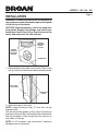
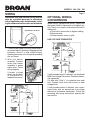
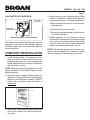
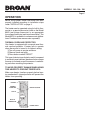
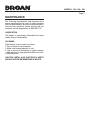
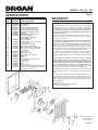
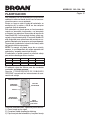
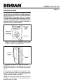
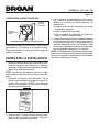
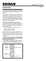
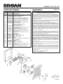
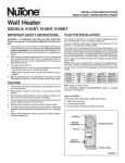
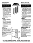
MODELS 192 • 194 • 198
Wall Heater
Page 1
READ AND SAVE THESE INSTRUCTIONS
IMPORTANT INSTRUCTIONS
READ ALL INSTRUCTIONS BEFORE
INSTALLING OR USING THIS HEATER.
To reduce the risk of fire, electric shock, or injury
to persons, observe the following:
1. Use this unit only in the manner intended
by the manufacturer. If you have questions,
contact the manufacturer at the address or
telephone number listed in the warranty.
2. Before servicing or cleaning unit, switch
power off at service panel and lock the service
disconnecting means to prevent power from
being switched on accidentally. When the
service disconnecting means cannot be
locked, securely fasten a prominent warning
device, such as a tag, to the service panel.
3.Installation work and electrical wiring
must be done by a qualified person(s) in
accordance with all applicable codes and
standards, including fire-rated construction
codes and standards.
4. When cutting or drilling into wall or ceiling,
do not damage electrical wiring and other
hidden utilities.
5. This heater is hot when in use. To avoid burns,
do not let bare skin touch hot surfaces. Keep
combustible materials, such as furniture,
pillows, bedding, papers, clothes, etc. and
curtains at least 3 feet (0.9 m) from the front
of the heater.
6. Extreme caution is necessary when any
heater is used by or near children or invalids
and whenever the heater is left operating
and unattended.
7.Do not operate any heater after it
malfunctions. Disconnect power at service
panel and have heater inspected by a
reputable electrician before reusing.
8. Do not use outdoors.
9.To disconnect heater, turn controls to
off, and turn off power to heater circuit at
main disconnect panel (or operate internal
disconnect switch, if provided).
10.Do not insert or allow foreign objects to
enter any ventilation or exhaust opening, as
this may cause an electric shock or fire, or
damage the heater.
11. To prevent a possible fire, do not block air
intakes or exhaust in any manner.
12.A heater has hot and arcing or sparking
parts inside. Do not use it in areas where
gasoline, paint, or flammable vapors or
liquids are used or stored.
13.Use this heater only as described in this
manual. Any other use not recommended
by the manufacturer may cause fire, electric
shock, or injury to persons.
14.Install heater at least 6 inches from floor or
any adjacent wall.
15.To avoid electrical shock: Do not install
unit in a tub or shower enclosure or any
location where it may come in contact with
water. Never place a switch where it can be
reached from a tub or shower.
16.
This product may ONLY be installed
horizontally in a wall. Do not mount in any
other position.
17. Do not connect heater to dimmer switch or
speed control.
18.This product must be grounded.
SAVE THESE INSTRUCTIONS
MODELS 192 • 194 • 198
Page 2
PLANNING
This heater is intended to be used to supply
supplemental heat from a wall location in new or
existing construction.
Choose a location where edge of heater will be
at least 12” from the floor or any adjacent vertical
surface.
The heater can be operated using its built-in thermostat or a remote thermostat (such as the Model
86W Line-Voltage thermostat or an appropriate
low-voltage thermostat and transformer/relay). The
Model 85 Kit is available for surface-mount applications. Purchase these accessories separately.
Plan to supply the heater with proper line voltage
and appropriate power cable.
NOTE: Power can be tapped from a nearby circuit
depending on the heater wattage required and the
amperage rating of the circuit.
Heater can be converted to half-wattage to avoid
overloading such circuits.
MODELVOLTS
192
194
198
AMPS
WATTS
BTU/HR
2408.33/4.17 2000/1000 6827/3413
24012.50/6.25 3000/1500 10240/5120
24016.67/8.33 4000/2000 13653/6827
Bold ratings are factory wired.
See “OPTIONAL WIRING CONVERSIONS” section for wattage conversion instructions.
DRYWALL
THERMAL
OVERLOAD
HEATER HOUSING
GRILLE
BUILT-IN
THERMOSTAT
POWER CABLE
Follow these basic steps when installing this heater:
1) Nail housing to studs.
2) Connect power cable.
3) Fasten heater assembly and grille to housing.
MODELS 192 • 194 • 198
Page 3
INSTALLATION
WARNING: To reduce the risk of fire, do not store or
use gasoline or other flammable vapors and liquids
in the vicinity of the heater.
CAUTION: High temperature, risk of fire, keep electrical cords, drapery, furnishings, and other combustibles at least 3 feet (0.9 m) from the front of the
heater and away from the side and rear.
THERMAL
OVERLOAD
“RESET”
BUTTON
HEATER
ASSEMBLY
MOUNTING
SCREWS
THERMOSTAT
1. Remove heater assembly from housing. Take out the
four (4) screws shown and set heater assembly aside.
NAIL HERE –
BOTH SIDES
MEASURING
GUIDES
2. Attach housing to wall studs.
NOTE: Locate housing at least 12” from floor on any
adjacent walls.
Use the measuring guides on the sides of housing to
position housing so that it will be flush with finished wall.
Nail the housing to studs through the hole and slot on
both sides of housing.
NOTE: In 24”-on-center stud construction, framing in
between studs is necessary.
MODELS 192 • 194 • 198
Page 4
WIRING
Installation work and electrical wiring must be
done by a qualified person(s) in accordance
with all applicable codes and standards, including fire-rated construction codes and standards.
GROUNDING CLIP DETAIL
OPTIONAL WIRING
CONVERSIONS
When using a separate wall control, simply turn
the heater’s built-in thermostat to its highest setting. There is no need to disconnect the built-in
thermostat:
a)Turn built-in thermostat to highest setting.
b)Remove knob.
c)Fasten security cover to grille.
LINE-VOLTAGE THERMOSTAT
1. Connect power cable to housing. Attach electrical power cable to housing using appropriate
connector. Allow 6” of wire inside housing.
Secure ground wire to housing with grounding
clip, as shown.
ç
2.Wi re t h e h e a te r
assembly. Connect
wires from heater
assembly to power
cable wires. Follow
wiring diagram.
If heater is wired
direct, use the builtin thermostat for
temperature control.
CUT WIRE
FOR
REMOTE
THERMOSTAT
If wall-mounted control is desired, use the Model
86W Line-Voltage Thermostat. Purchase thermostat separately.
Cut blue wire. Strip ½” of insulation from each
end. Connect wires from wall control to each
stripped wire.
If wall-mounted control is desired, use a transfomer/relay with an appropriate low-voltage
thermostat (purchase separately). Follow the
mounting and wiring instructions packed with
the controls.
MODELS 192 • 194 • 198
Page 5
HALF-WATTAGE CONVERSION
TOP / FRONT
OF HEATER
4. Attach security cover to grille (optional). When
heater is installed in a public area without a
separate wall control, it is recommended that:
a)Built-in thermostat be set to desired temperature level.
REMOVE THIS
JUMPER WIRE
HEATER CONVERTED TO HALF-WATTAGE
The heater will produce less heat and use less
electricity if converted to half-wattage. Remove
the black jumper wire from the heating element
and discard wire.
COMPLETE THE INSTALLATION
1. Install housing mask. A housing mask has
been provided to keep construction dust,
drywall spray, paint, etc., from damaging the
heater. Bend the flap on the mask and push it
into the heater housing.
NOTE: Mask can be put into place before or after
heater assembly is reinstalled. Remove mask
before operation.
2. Reinstall heater assembly. Secure heater assembly to housing with four (4) screws. Check
thermal overload button marked “RESET”.
Heater will not operate unless this button is
depressed.
3. Install grille. Place grille over heater and attach
with four (4) screws. Push knob onto thermostat stem.
b)Thermostat knob be removed.
c)Security cover be attached to grille with two
(2) screws, provided.
5. Check operation. Turn on power at service
entrance. Turn thermostat to its highest setting
and make sure heating element and blower
come on. Then turn it to its lowest setting and
make sure element and blower shut off.
NOTE: The fan delay prevents the fan from coming on until the element is hot. Likewise, it keeps
the fan running until the element cools down.
MODELS 192 • 194 • 198
Page 6
OPERATION
Before using heater, make sure heater has been
properly installed according to installation steps
under “INSTALLATION” on page 3.
The heater can be operated using its built-in thermostat or a remote thermostat (such as the Model
86W Line-Voltage thermostat or an appropriate
low-voltage thermostat and transformer/relay). The
Model 85 Kit is available for surface-mount applications. Purchase these accessories separately.
THERMAL OVERLOAD PROTECTOR
Your heater is equipped with a manual-reset thermal overload protector. If heater fails to operate
when thermostat is turned to its highest setting:
1)Turn off power at service entrance.
2)Remove knob and grille.
3)Press button marked “RESET”.
This type of device is particularly useful (compared
to automatic reset devices) because it encourages
the user to find and correct the cause of overheating unit when resetting the protector.
TO AVOID PROPERTY DAMAGE WHEN USING
THIS HEATER TO PREVENT FREEZE-UPS:
Make sure heater functions properly before leaving unattended. A tripped protector will prevent the
heater from operating.
DRYWALL
THERMAL
OVERLOAD
HEATER HOUSING
GRILLE
BUILT-IN
THERMOSTAT
POWER CABLE
MODELS 192 • 194 • 198
Page 7
MAINTENANCE
The following maintenance and cleaning tasks
can be performed by the user. All other servicing
must be performed by an authorized technician If
you have any questions, please consult with our
customer service department at: 800-558-1711.
LUBRICATION
The heater is permanently lubricated and never
needs oiling or disassembly.
CLEANING
Clean heater once a month as follows:
1. Turn off power at service panel.
2. Make sure heating element is cool.
3. Use a soft brush attachment to gently vacuum
grille openings or wipe grille clean with a soft cloth.
4. Restore power.
CAUTION: METAL AND ELECTRICAL PARTS
SHOULD NEVER BE IMMERSED IN WATER.
MODELS 192 • 194 • 198
SERVICE PARTS
KEY
NO.
PART
NUMBER
1
2
3
4
5
6
7
8
9
10
11
12
97009334Housing
99390015
Grounding Clip
99030190
Fan Delay
98006989 Element Bracket (2 Required)
99271155
Heating Element (Model 192)
99270723 Heating Element (Model 194)
99270724 Heating Element (Model 198)
99400061 Bushing
97008688
Black Wire Assembly (29–1/2”)
97008690
Black Jumper Wire
*
Thermal Overload Bracket
*
Thermal Overload
97008692
Red Power Wire
99150491 Screw, 8–18 x 3/8 Ph. Pan Head
(14 Required)
97008683
Partition Plate Assembly
93270619 Wire Clamp ( 3 Required)
99260425 Nut, 8–32 Hex Keps (2 Required)
99160350 Screw, 6–32 x 1/4 Ph. Pan Head
(2 Required)
99030324 Thermostat
99080251 Motor (Model 198)
99080249 Motor (Models 192 & 194)
99020255 Fan Blade
97013822 Grille
99150478 Screw, 8–18 x 3/8 PH Truss Hd.
(4 Required)
99090683 Grille Logo
99360136 Knob
99110687
Security Cover
93150462
Screw, 8–18 x 5/8 Oval Head (2 Required)
97013945
Assembly, Thermal Overload (Includes
Key Nos. 9, 10, & 12 (2))
13
14
15
20
21
22
23
24
25
26
27
29
30
31
*
PART DESCRIPTION
Page 8
WARRANTY
BROAN-NUTONE ONE YEAR LIMITED WARRANTY
Broan-NuTone warrants to the original consumer purchaser of its products
that such products will be free from defects in materials or workmanship
for a period of one year from the date of original purchase. THERE ARE NO
OTHER WARRANTIES, EXPRESS OR IMPLIED, INCLUDING, BUT NOT LIMITED TO, IMPLIED WARRANTIES OF MERCHANTABILITY OR FITNESS FOR
A PARTICULAR PURPOSE.
During this one-year period, Broan-NuTone will, at its option, repair or replace, without charge, any product or part which is found to be defective
under normal use and service.
THIS WARRANTY DOES NOT EXTEND TO FLUORESCENT LAMP STARTERS,
TUBES, HALOGEN AND INCANDESCENT BULBS, FUSES, FILTERS, DUCTS,
ROOF CAPS, WALL CAPS AND OTHER ACCESSORIES FOR DUCTING. This
warranty does not cover (a) normal maintenance and service or (b) any
products or parts which have been subject to misuse, negligence, accident,
improper maintenance or repair (other than by Broan-NuTone), faulty installation or installation contrary to recommended installation instructions.
The duration of any implied warranty is limited to the one-year period as
specified for the express warranty. Some states do not allow limitation on
how long an implied warranty lasts, so the above limitation may not apply
to you.
BROAN-NUTONE’S OBLIGATION TO REPAIR OR REPLACE, AT BROANNUTONE’S OPTION, SHALL BE THE PURCHASER’S SOLE AND EXCLUSIVE
REMEDY UNDER THIS WARRANTY. BROAN-NUTONE SHALL NOT BE LIABLE
FOR INCIDENTAL, CONSEQUENTIAL OR SPECIAL DAMAGES ARISING OUT
OF OR IN CONNECTION WITH PRODUCT USE OR PERFORMANCE. Some
states do not allow the exclusion or limitation of incidental or consequential
damages, so the above limitation or exclusion may not apply to you.
This warranty gives you specific legal rights, and you may also have other
rights, which vary from state to state. This warranty supersedes all prior warranties.
To qualify for warranty service, you must (a) notify Broan-NuTone at the address or telephone number below, (b) give the model number and part identification and (c) describe the nature of any defect in the product or part. At
the time of requesting warranty service, you must present evidence of the
original purchase date.
Broan-NuTone LLC
926 W. State Street, Hartford, Wisconsin 53027
www.broan.com 800-558-1711
Product specifications
subject to change
without notice.
99045032A
MODELOS 192 • 194 • 198
Calentador de la Pared
Página 9
LEA Y CONSERVE ESTAS INSTRUCCIONES
INSTRUCCIONES IMPORTANTES
LEA TODAS LAS INSTRUCCIONES ANTES DE
INSTALAR O USAR ESTE CALENTADOR.
Para reducir el riesgo de incendios, descargas
eléctricas o lesiones personales, observe las
siguientes precauciones:
1. Use la unidad solo de la manera indicada por el
fabricante. Si tiene preguntas, comuníquese con
el fabricante a la dirección o al número telefónico
que se incluye en la garantía.
2. Antes de dar servicio a la unidad o de limpiarla,
interrumpa el suministro eléctrico en el panel de
servicio y bloquee los medios de desconexión
del servicio para evitar que la electricidad se
reanude accidentalmente. Cuando no sea
posible bloquear los medios de desconexión
del servicio, fije firmemente una señal de
advertencia (como una etiqueta) en un lugar
visible del panel de servicio.
3. El trabajo de instalación y el cableado eléctrico
deben estar a cargo de personal capacitado,
de acuerdo con todos los códigos y normas
correspondientes, incluidos los códigos y
normas de construcción específicos sobre
protección contra incendios.
4. Al cortar o perforar a través de la pared o
del cielo raso, tenga cuidado de no dañar el
cableado eléctrico ni otros servicios ocultos.
5. Este calentador se calienta cuando se usa. Para
evitar quemaduras, no deje que la piel desnuda
toque las superficies calientes. Mantenga
materiales combustibles como muebles,
almohadas, ropa de cama, papeles, ropa, etc.,
así como las cortinas, por lo menos a 3 pies (0.9
m) de la parte delantera del calentador.
6. Es necesario tener extremo cuidado cuando se
use un calentador cerca de niños o personas
inválidas, y siempre que el calentador se deje
funcionando y sin atención.
7. No haga funcionar ningún calentador después
de que presente una falla. Desconecte la
energía eléctrica en el panel de servicio y pida
que un electricista acreditado inspeccione el
calentador antes de volverlo a usar.
8. No lo use en exteriores.
9. Para desconectar el calentador, mueva los
controles a la posición de apagado y desconecte
la energía eléctrica al circuito del calentador en
el panel de desconexión principal (o active el
interruptor de desconexión interna, si existe).
10.No inserte ni permita que objetos extraños
entren en la abertura de ventilación o de escape,
pues esto puede ocasionar una descarga
eléctrica, un incendio o daños al calentador.
11. Para prevenir un posible incendio, no bloquee
la entrada o salida del aire de ninguna manera.
12.El calentador tiene piezas calientes y que
pueden generar arcos eléctricos o chispas en
el interior. No lo use en áreas donde se use o
almacene gasolina, pintura o vapores o líquidos
flamables.
13.Use este calentador solamente como se
describe en este manual. Cualquier otro uso no
recomendado por el fabricante puede ocasionar
un incendio, una descarga eléctrica o lesiones
a personas.
14. Instale el calentador por lo menos 6 pulg. desde
el piso o cualquier pared adyacente.
15. Para evitar golpe eléctrico: No instale la unidad
en una bañera o recinto de ducha. Nunca
coloque un interruptor en un lugar que pueda
ser alcanzado desde una bañera o ducha.
16. Este producto SOLAMENTE se puede instalar
en una pared. No lo monte en ninguna otra
posicion.
17. No conecte el calentador a un variador de luz o
control de velocidad.
18. Este producto debe ser conectado a tierra.
GUARDE ESTAS INSTRUCCIONES
MODELOS 192 • 194 • 198
Página 10
PLANIFICACION
Este calentador ha sido diseñado para proporcionar
calefacción adicional desde el cielo raso en una construcción nueva o una ya existente.
Escoja un lugar en que el borde del calentador se
encuentre por lo menos a 30,48 cm de cualquier
superficie vertical adyacente.
Este calentador se puede poner en funcionamiento
usando su termostato incorporado o un termostato
a distancia (por ejemplo el termostato de tensión de
línea Modelo 86 o un termostato de bajo voltaje apropiado y transformador/relé). El conjunto Modelo 85
está disponible para aplicaciones de montaje en superficie. Adquiera estos accesorios en forma separada.
Proporcione al calentador la tensión de línea y cable
de energía eléctrica apropiados.
NOTA: La energía se puede tomar de un circuito
cercano, lo que dependerá del vatiaje requerido del
calentador y amperaje nominal del circuito.
El calentador se puede convertir a mitad de vatiaje
para evitar sobrecargar dichos circuitos.
MODELO VOLTIOS
192
240
194
240
198
240
AMPS
VATIOS
BTU/HR
8.33/4.17 2000/1000 6827/3413
12.50/6.25 3000/1500 10240/5120
16.67/8.33 4000/2000 13653/6827
El cableado viene de fábrica para las corrientes
nominales en letras oscuras.
Sección “CONVERSIONES DE CABLEADO
ORIGINAL” encontrará las instrucciones de conversión de vatiaje.
PARED DE YESO
SOBRECARGA TERMICA
CAJA DEL
CALENTADOR
REJILLA
TERMOSTATO
INCORPORADO
CABLE
DE ENERGIA
ELECTRICA
Al instalar este calentador, siga estos pasos básicos:
1) Clave la caja en las vigas.
2) Conecte el cable de energía eléctrica.
3) Fije el conjunto del calentador y la rejilla a la caja
MODELOS 192 • 194 • 198
Página 11
INSTALACION
ADVERTENCIA: Para reducir el riesgo de incendio,
no almacene ni use gasolina u otros vapores y
líquidos flamables en las cercanías del calentador.
PRECAUCIÓN: Temperatura alta, el riesgo de
incendio, mantenga los cables eléctricos, cortinas,
muebles y otros materiales combustibles por lo
menos 3 pies (0,9 m) del frente del calentador y
lejos de la cara y la parte trasera.
BOTON “RESET”
DE SOBRE
CARGA
TERMICA
TORNILLOS DE
MONTAJE DEL
CONJUNTO DEL
CALENTADOR
TERMOSTATO
1.Saque el conjunto de calentador de la caja.
Saque los cuatro (4) tornillos que se muestran
y saque el conjunto del calentador.
CLAVE AQUI
– EN AMBOS
LADOS
GUIDAS DE
MEDIDA
2. Enganche la caja en las vigas de la pared.
NOTA: Sitúe la caja a una distancia por lo menos
de 30,48 cm del piso o de cualquier pared adyacente.
Use las guías de medida al costado de la caja,
a fin de colocarla a nivel con la pared terminada.
Clave la caja a las vigas a través del agujero y la
ranura en ambos lados de la caja.
NOTA: En una construcción de vigas con centro
de 60,96 cm (24 pulg.), se hace necesaria una
armazón entre las vigas.
MODELOS 192 • 194 • 198
CABLEADO
El trabajo de instalación y el cableado eléctrico
deben estar a cargo de personal capacitado,
de acuerdo con todos los códigos y normas
correspondientes, incluidos los códigos y normas
de construcción específicos sobre protección
contra incendios.
1. Conecte el
cable de
DETALLE DEL SUelectricidad
JETADOR (CLIP) DE
CONEXIÓN A TIERRA
a la caja.
Conecte el
cable de
energía
eléctrica a la
caja usando
el conector
adecuado.
Deje 15,24 cm (6 pulg.) de cable dentro de la caja.
Fije firmemente a la caja el cable de conexión a
tierra con el sujetador, tal como se muestra.
Al usar un control de pared separado, prenda el
termostato incorporado al calentador en su graduación más alta. No es necesario desconectar el
termostato incorporado.
Para evitar un ajuste descendente no deseado del
termostato incorporado:
a) Ponga el termostato incorporado en su
graduación más alta.
b) Quite la perilla.
c) Fije la cubierta de seguridad a la rejilla.
TERMOSTATO DE TENSIÓN DE LÍNEA
ç
2. Cableado del conjunto
de calentador. Conecte
los alambres del conjunto de calentador a
los alambres de cable
de energía. Siga el
diagrama de cableado.
Si el calentador está
cableado en forma
directa, use el termostato incorporado para
el control de temperatura.
CONVERSIONES DE
CABLEADO OPCIONAL
Página 12
CORTE
EL CABLE
PARA EL
TERMOSTATO
REMOTO
Si se desea control montado en la pared, use el
termostato de tensión de línea Modelo 86W. Compre el termostato por separado.
Corte el cable azul. Quite 1,27 cm (½ pulg.) de
aislamiento en cada extremo. Conecte los cables
del control de pared con cada cable desnudo.
Si se desea control montado en la pared, uso un
termostato de bajo voltaje apropiado (compre por
separado). Siga las instrucciones de montaje y
cableado que vienen con los controles.
MODELOS 192 • 194 • 198
Página 13
CONVERSIÓN A MITAD DE VATIAJE
PARTE
SUPERIOR /
FRENTE DE
CALENTADOR
QUITE ESTE
ALAMBRE DE
CIERRE
CALENTADOR CONVERTIDO A MITAD DE VATIAJE
El calentador producirá menos calor y usará menos
electricidad si se le convierte a mitad de vatiaje.
Saque del elemento de calor el alambre negro de
puente y bote éste.
COMPLETE LA INSTALACION
1. Instale la cubierta de la caja. Se provee una cubierta de caja para evitar que el polvo de la construcción, rocíos de yeso, pintura, etc., dañen el
calentador. Doble la aleta de la cubierta y póngala
dentro de la caja del calentador.
NOTA: La cubierta se pueded colocar en su lugar
antes o después de reinstalar el conjunto del calentador.
2. Reinstale el conjunto del calentador. Fije el
conjunto del calentador a la caja con cuatro (4)
tornillos. Mire el botón “RESET” de sobrecarga
térmica. El calentador no funcionará a menos
que el botón esté oprimido.
3. Instale la rejilla. Coloque la rejilla sobre el calentador y fíjelo con cuatro (4) tornillos. Empuje la
perilla en el vástago del termostato.
4. Fije la cubierta de seguridad a la rejilla (opcional). Cuando se instala el calentador en un área
pública sin un control de pared separado, se
recomienda:
a)Graduar el termostato incorporado al nivel de
temperatura deseado.
b)Quitar la perilla del termostato.
c)Fijar la cubierta de seguridad a la rejilla con
dos (2) tornillos, que se proveen.
5. Compruebe el funcionamiento. Conecte la energía
en la entrada de servicio. Active el termostato en
su graduación más alta y compruebe que se
activen el elemento de calor y el soplador. Luego
actívelo en su graduación más baja y compruebe
que se apaguen el elemento y el soplador.
NOTA: El retrasador del ventilador evita que el ventilador se active hasta que el elemento esté caliente.
Asimismo, mantiene al ventilador en funcionamiento
hasta que el elemento se enfríe.
MODELOS 192 • 194 • 198
Página 14
OPERACIÓN
Antes de usar el calentador, asegúrese de que esté
instalado adecuadamente, de acuerdo con los pasos
de instalación indicados en “INSTALACION” en la
página 9.
El calentador de puede ser operado usando su builtin termostato o un termostato remoto (tales como
el Modelo 86W termostato de Line-Voltage o un
termostato de baja-voltaje apropiado y el transformador / relé). El 85 Kit Modelo está disponible para
aplicaciones superficie de-de montaje en. Compra
estos accesorios por separado.
PROTECTOR DE SOBRECARGA TERMICA
Su calentador cuenta con un protector de sobrecarga
térmica de reposición manual. Si el calentador no
funciona cuando el termostato está activado en su
graduación más alta:
1)Corte la energía en la entrada de servicio.
2)Saque la perilla y la rejilla.
3)Oprima el botón “RESET”.
Este tipo de dispositivo es especialmente útil (comparado con los de reposición automática), ya que
alienta al usuario a encontrar y corregir la causa
del sobrecalentamiento de una unidad al reajustar
el protector.
A FIN DE EVITAR DAÑOS A LA PROPIEDAD
CUANDO SE USE ESTE CALENTADOR PARA
EVITAR CONGELAMIENTOS:
COMPRUEBE que el calentador funciona correctamente ANTES de dejarlo desatendido. Un protector
desconectado evitará que el calentador opere.
DRYWALL
THERMAL
OVERLOAD
HEATER HOUSING
GRILLE
BUILT-IN
THERMOSTAT
POWER CABLE
MODELOS 192 • 194 • 198
Página 15
MAINTENIMIENTO
El usuario puede realizar las siguientes tareas
de mantenimiento y limpieza. Todos los demás
servicios los debe realizar un técnico autorizado. Si
tiene preguntas, consulte a nuestro departamento
de servicio al cliente llamando al: 800-558- 1711.
LUBRICACIÓN
El calentador está permanentemente lubricado
y nunca necesitará ponerle aceite ni desarmarlo.
LIMPIEZA
Limpie el calentador una vez al mes tal como sigue:
1. Apague la energía eléctrica en el panel de servicio.
2. Asegúrese de que el elemento de calefacción
esté frío.
3. Use un aditamento de cepillo suave para aspirar
suavemente aberturas de la rejilla o limpie la
rejilla con un paño suave.
4. Restaure la energía eléctrica.
CUIDADO – LAS PIEZAS METALICAS Y ELECTRICAS NUNCA SE DEBEN SUMERGIR EN
AGUA.
MODELOS 192 • 194 • 198
LISTA DE PIEZAS
NUMERO
REF. DE PIEZAS
1
2
3
4
5
6
7
8
9
10
11
12
13
14
15
20
21
22
23
24
25
26
27
29
30
31
*
DESCRIPCION
97009334Caja
99390015
Sujetador de toma de tierra
99030190
Retraso de ventilador
98006989 Soporte del elemento (Se requieren 2)
99271155
Elemento de calefacción (Modelo 192)
99270723 Elemento de calefacción (Modelo 194)
99270724 Elemento de calefacción (Modelo 198)
99400061 Manguito aislador
97008688 Conjunto de alambre negro (74,93 cm)
97008690 Alambre de puente
*
Soporte de sobrecarga térmica
*
Sobrecarga térmica
97008692 Alambre de energía rojo
99150491 Tornillo phillips, cabeza grande. 8-18 x 3/8
(se requieren 14)
97008683 Conjunto de placa de separación
93270619 Sujetador del alambre (se requieren 3)
99260425 Tuerca, Keps hexagonales de 8-32 (se
requieren 2)
99160350 Tornillo, cabeza móvil ph 6-32 x 1/4 (se
requieren 2)
99030324 Termostato
99080251 Motor (Modelo 198)
99080249 Motor (Modelos 192 & 194)
99020255 Paleta de ventilador
97013822 Rejilla
99150478 Tornillo de ranura, 8-18 x 3/8 PH Truss Hd.
(se requieren 4)
99090683 Logotipo de rejilla
99360136 Perilla
99110687
Cubierta de seguridad
93150462 Tornillo, cabeza ovalada 8-18 x 5/8 (se
requieren 2)
97013945
Conjunto de sobrecarga térmica (Incluye
Numero de Codigo 9, 10, y 12 (2))
GARANTIA
Página 16
GARANTIA BROAN-NUTONE LIMITADA POR UN AÑO
Broan-NuTone garantiza al consumidor comprador original de sus productos que
dichos productos carecerán de defectos en materiales o en mano de obra por un
período de un año a partir de la fecha original de compra. NO EXISTEN OTRAS
GARANTIAS, EXPLICITAS O IMPLICITAS, INCLUYENDO, PERO NO LIMITADAS
A, GARANTIAS IMPLICITAS DE COMERCIALIZACION O APTITUD PARA UN
PROPOSITO PARTICULAR.
Durante el período de un año, y a su propio criterio, Broan-NuTone reparará
o reemplazará, sin costo alguno cualquier producto o pieza que se encuentre
defectuosa bajo condiciones normales de servicio y uso.
LA PRESENTE GARANTÍA NO CUBRE LOS TUBOS FLUORESCENTES NI SUS
ARRANCADORES, BOMBILLAS DE HALÓGENO E INCANDESCENTES, FUSIBLES, FILTROS, CONDUCTOS, TAPONES DE TECHO O PAREDES Y DEMÁS
ACCESORIOS PARA CONDUCTOS. Esta garantía no cubre (a) mantenimiento y
servicio normales o (b) cualquier producto o piezas que hayan sido utilizadas de
forma errónea, negligente, que hayan causado un accidente, o que hayan sido
reparadas o mantenidas inapropiadamente (por otras compañías que no sean
Broan-NuTone), instalación defectuosa, o instalación contraria a las instrucciones
de instalación recomendadas.
La duración de cualquier garantía implícita se limita a un período de un año como
se especifica en la garantía expresa. Algunos estados no permiten limitaciones en
cuanto al tiempo de expiración de una garantía implícita, por lo que la limitación
antes mencionada puede no aplicarse a usted.
LA OBLIGACION DE BROAN-NUTONE DE REPARAR O REEMPLAZAR, SIGUIENDO
EL CRITERIO DE BROAN-NUTONE, DEBERA SER EL UNICO Y EXCLUSIVO
RECURSO LEGAL DEL COMPRADOR BAJO ESTA GARANTIA. BROAN-NUTONE
NO SERA RESPONSABLE POR DAÑOS INCIDENTALES, CONSIGUIENTES, O
POR DAÑOS ESPECIALES QUE SURJAN A RAIZ DEL USO O DESEMPEÑO DEL
PRODUCTO. Algunos estados no permiten la exclusión o limitación de daños
incidentales o consiguientes, por lo que la limitación antes mencionada puede
no aplicarse a usted.
Esta garantía le proporciona derechos legales específicos, y usted puede también
tener otros derechos, los cuales varían de estado a estado. Esta garantía reemplaza
todas las garantías anteriores.
Para calificar en la garantía de servicio, usted debe (a) notificar a Broan-NuTone
al domicilio o al número de teléfono que se menciona abajo, (b) dar el número
del modelo y la identificación de la pieza, y (c) describir la naturaleza de cualquier
defecto en el producto o pieza. En el momento de solicitar servicio cubierto por
la garantía, usted debe de presentar evidencia de la fecha original de compra.
Broan-NuTone LLC
926 W. State Street, Hartford, Wisconsin 53027
www.broan.com 800-558-1711
Especificaciones
de producto conforme
a cambio sin el aviso.
99045032A