1
Table of Contents
IMPORTANT–Please Read and Follow!
Warnings & Important Information_____________________________________________________ 3
Professional Side-by-Side
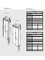
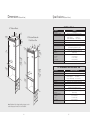
Dimensions & Specifications (Professional 42” & 48”) ________________________________ 6
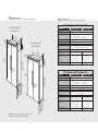
Dimensions & Specifications (Professional 42” & 48” with flush mount trim) _____________8
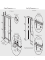
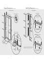
Cutout Dimensions (42”) _________________________________________________________10
Anti-Tip Dimensions (42”) ________________________________________________________11
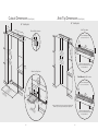
Cutout Dimensions (48”)_________________________________________________________ 12
Anti-Tip Dimensions (48”)________________________________________________________ 13
Professional Bottom-Mount
Dimensions & Specifications (36”)_________________________________________________ 14
Cutout Dimensions (36”)_________________________________________________________ 16
Anti-Tip Dimensions (36”)________________________________________________________ 17
Cabinet Information (Professional) ____________________________________________________ 18
Cabinet Information (Professional with flush mount trim) ________________________________ 20
Custom Side Panel Dimensions (Professional) __________________________________________ 22
Custom Side Panel Dimensions (Professional with flush mount trim) ______________________ 23
General Information ________________________________________________________________ 24
Unpacking & Moving _______________________________________________________________ 26
Flush Mount Side Trim Installation ____________________________________________________ 27
Installation_________________________________________________________________________ 27
Hinge Adjustment ______________________________________________________________ 28
Kickplate Installation ____________________________________________________________ 30
Door Stop Adjustment __________________________________________________________ 31
Water Filter Installation __________________________________________________________ 32
System Specifications and Data___________________________________________________ 33
Final Installation ________________________________________________________________ 34
Performance Checklist ______________________________________________________________ 35
Control Panels _____________________________________________________________________ 36
Service & Registration_______________________________________________________________ 37
2
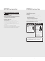
• Make sure that incoming voltage is the same
as unit rating. An electric rating plate
specifying voltage, frequency, wattage,
amperage, and phase is attached to the
product.
Your safety and the safety of others is
very important.
We have provided many important safety
messages in this manual and on your
appliance. Always read and obey all
safety messages.
• To reduce the risk of fire, electric shock, or
injury to persons, installation work and
electrical wiring must be done by qualified
people in accordance with all applicable
codes and standards, including fire-rated
construction.
This is the safety alert symbol. This
symbol alerts you to hazards that
can kill or hurt you and others.
All safety messages will be preceded by the
safety alert symbol and the word“DANGER”
or “WARNING.” These words mean:
• The installer should leave these instructions
with the consumer who should retain them
for local inspector’s use and for future
reference.
D A N G E R
You will be killed or seriously injured if
you don’t follow instructions.
WARNING
You can be killed or seriously injured if
you don’t follow instructions.
All safety messages will identify the
hazard, tell you how to reduce the chance
of injury, and tell you what can happen if
the instructions are not followed.
3