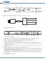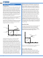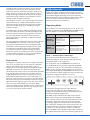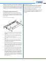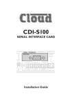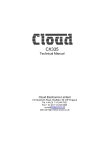
1
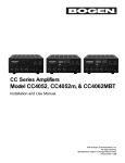
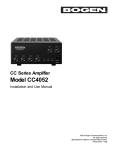
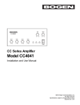
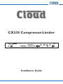
CX335 Compressor-Limiter CX 335 GAIN REDUCTION OUTPUT DISPLAY KNEE NORMAL SOFT SLOW HARD THRESHOLD -10 L 30 20 15 10 Power ENVELOPE 6 4 2 1 0dB -20 -16 -12 -8 -4 0dB +4 +8 +12 3 -20 dBu 1.2 :1 - 10 20 5 GAIN PEAK 5 10 -15 1.5 +10 R RATIO 2 0 Split Band Compressor-Limiter 6 15 0 4 + BYPASS 4 3 0 -2 -4 20 26 -6 dBu 8 8 12 LIMIT NORMAL 12 dB BYPASS Installation Guide CX335 User Manual v1.0 1 Important Safety Instructions WARNING: To reduce the risk of fire or electric shock, do not expose this appliance to rain or moisture. CAUTION: Use of controls or adjustments or performance of procedures other than those specified may result in hazardous radiation exposure. CAUTION RISK OF ELECTRIC SHOCK DO NOT OPEN WARNING: SHOCK HAZARD - DO NOT OPEN AVIS: RISQUE DE CHOC ÉLECTRIQUE - NE PAS OUVRIR The lightning flash with the arrowhead symbol within an equilateral triangle, is intended to alert you to the presence of uninsulated dangerous voltages within the product’s enclosure that may be of sufficient magnitude to constitute a risk of electric shock. The exclamation point within an equilateral triangle is intended to alert the user to the presence of important operating and maintenance (servicing) instructions in the literature accompanying the appliance. 1. Read these instructions. 2. Keep these instructions. 3. Heed all warnings. 4. Follow all instructions. 5. Clean only with dry cloth. 6. Do not use this apparatus near water. 7. Do not install near any heat sources such as radiators, heat registers, stoves, or other apparatus (including amplifiers) that produce heat. 8. Do not defeat the safety purpose of the polarized or grounding-type plug. A polarized plug has two blades with one wider than the other. A grounding type plug has two blades and a third grounding prong. The wide blade or the third prong are provided for your safety. If the provided plug does not fit into your outlet, consult an electrician for replacement of the obsolete outlet. 9. Protect the power cord from being walked on or pinched particularly at plugs, convenience receptacles, and the point where they exit from the apparatus. 10. Only use attachments/accessories specified by the manufacturer. 11. Use only with the cart, stand, tripod, bracket, or table specified by the manufacturer, or sold with the apparatus. When a cart is used, use caution when moving the cart/apparatus combination to avoid injury from tip-over. 12. Unplug this apparatus during lightning storms or when unused for long periods of time. 13. Refer all servicing to qualified service personnel. Servicing is required when the apparatus has been damaged in any way, such as power-supply cord or plug is damaged, liquid has been spilled or objects have fallen into the apparatus, the apparatus has been exposed to rain or moisture, does not operate normally, or has been dropped. 14. No naked flames, such as lighted candles, should be placed on the apparatus. WARNING: Excessive sound pressure levels from earphones and headphones can cause hearing loss. 2 CX335 User Manual v1.0 Contents Important Safety Instructions...................... 2 Safety Information......................................... 4 Safety notes regarding installation....................... 4 Conformities............................................................. 4 Power supply............................................................ 4 CAUTION – Servicing........................................... 4 General Description....................................... 5 CX335 main features.............................................. 5 What’s in the Box.................................................... 5 Block Diagram.......................................................... 6 Front panel descriptions........................................ 6 Rear panel descriptions.......................................... 7 Installation...................................................... 8 Mechanical................................................................. 8 Connections and adjustments.............................. 8 Chassis Ground Terminal.....................................10 Fitting the tamper-proof cover...........................10 Operating principles.................................... 10 Compression..........................................................10 Hard/Soft Knee......................................................11 Normal/Slow Envelope.........................................11 Peak limiter.............................................................11 Adjustments................................................. 12 Operating modes...................................................12 Appendix....................................................... 14 Changing the AC Voltage setting.........................14 EMC considerations..............................................14 Earthing....................................................................14 Technical Specifications........................................15 CX335 User Manual v1.0 3 Safety Information Safety notes regarding installation • • • • • • • Do not expose this unit to water or moisture Do not expose the unit to naked flames. Do not block or restrict any air vent Do not operate the unit in ambient temperatures above 45°C The unit has no internal user adjustable parts. Do not remove any panel. Refer any servicing to qualified service personnel. Do not replace the power transformer with any other type Conformities The Cloud CX335 conforms to the following European EMC Standards: BS EN 55103-1:2009 BS EN 55103-2:2009 These products have been tested for normal use in the commercial and light industrial environment. If the equipment is used in controlled EMC environments, the urban outdoors, heavy industrial environments or close to railways, transmitters, overhead power lines etc., the performance of the units may be degraded. The Cloud CX335 conforms to the following European electrical safety standard: BS EN 60065:2002 Power supply The CX335 has an internal PSU (Power Supply Unit) and is mains-powered via a standard 3-pin IEC receptacle located on the rear panel. The internal mains transformer has a primary winding with both 230 V and 115 V tappings, enabling the unit to be operated from mains voltages in the ranges 220 V to 240 V, or 110 V to 120 V. The voltage range to which the transformer tapping has been set in the factory – either ‘230 V’ or ‘115 V’ - will be clearly marked on the rear panel, immediately below the IEC receptacle. Check that this figure matches the voltage of the AC mains supply in your region. If it does not, the transformer tappings will need to be altered; in this case, please carry out the adjustments detailed on page 14 BEFORE connecting the CX335 to the mains supply for the first time. The unit must be earthed. Ensure that the mains power supply provides an effective earth connection using a three-wire termination. When the mains push-button switch is in the ‘out’ position, the live and neutral conductors of the mains transformer are disconnected. CAUTION – Servicing Do not touch any part or terminal carrying the hazardous live symbol ( ) while power is supplied to the unit. The unit contains no user serviceable parts. Refer servicing to qualified service personnel. Do not perform servicing unless you are qualified to do so. Disconnect the power cable from the unit before removing the top or bottom panel. Only reassemble the unit using bolts/screws identical to the original parts. 4 CX335 User Manual v1.0 General Description The Cloud CX335 is a two-channel compressor-limiter designed for permanent installation as part of the sound system in a pub, club, bar or similar premises where automatic, fool-proof control of the maximum sound level is required. The automatic nature of its operation permits the number of controls to be reduced, making setting up on-site a simple procedure. When inserted in the analogue signal chain immediately before the system power amplifiers (but see “Signal path considerations” on page 8) the CX335 will limit the dynamic range of the signal fed to the amplifiers, providing both control of the overall sound level and protection against amplifier and loudspeaker overload. A single set of controls affects both channels simultaneously. The controls are hidden behind a tamper-proof security cover once the unit is installed, to prevent unauthorised alteration. The inputs and outputs are electronically balanced on rear panel XLR connectors. The unit can accept signal levels of up to +26 dBu. The CX335 is extremely transparent in operation and when set correctly, imposes minimum colouration on the audio programme. CX335 main features • Stereo compressor-limiter for dynamic range control and amplifier/speaker protection in fixed audio installations • Fully analogue design • Electronically balanced inputs and outputs on rear panel XLRs • +26 dBu maximum input and output levels • Automatic operation with minimal controls – very simple to set up • Transparent in operation • Separate peak limiter section with LED indication • Bargraph meters for output level and gain reduction • Bypass switch • Anti-tamper security cover with single-use seals • VCA control port for Music Muting or remote level control • 1U 19” rackmounting unit • Five year warranty What’s in the Box Please check the shipping carton for damage before opening. If there is damage, please contact your Cloud agent and the shippers. The packing carton should contain the following items: • CX335 compressor-limiter • Security kit, consisting of: -- Front panel security cover -- 2 x fixing brackets -- 2qty M3 x 15 hex pillars -- 2qty M3 x 6 hex-head screws -- 2 mm AF hex key -- 2 x “single-use” security tags • IEC mains lead with mains plug appropriate to your region • This manual CX335 User Manual v1.0 5 Block Diagram Mixer or Zoner Loudspeaker Systems Audio Sources Example System Signal Path (see “Signal path considerations” on page 8) Multi-Channel Amplifier. CX335 Front panel descriptions C X 335 GAIN REDUCTION OUTPUT DISPLAY 30 20 15 10 1. 2. 3. 4. 5. 6. 7. 8. 9. 10. 11. 12. 6 1 KNEE NORMAL SOFT THRESHOLD SLOW HARD dBu :1 dBu LIMIT dB 7 8 2 3 4 5 6 -10 L 6 4 2 1 0dB -20 -16 -12 -8 -4 0dB +4 +8 +12 11 10 RATIO 2 3 -20 1.2 - 10 20 5 GAIN PEAK 5 10 -15 1.5 +10 R Power 12 ENVELOPE 0 Split Band Compressor-Limiter 6 15 0 4 + BYPASS 4 3 0 -2 -4 20 26 -6 8 8 12 NORMAL 12 BYPASS 5 12 Power switch with integral LED THRESHOLD – rotary control setting the signal level above which the compressor-limiter applies gain reduction. RATIO – rotary control setting the degree of compression applied to signals above the threshold. PEAK – rotary control setting the signal level at which the (independent) peak limiter operates. LIMIT – red LED, illuminates when the peak limiter is active. GAIN – adjust to match the output level to the input level on normal programme material when the CX335 is active. ENVELOPE – push-button switch: Out = ‘Normal’; In = “Slow”. Select to obtain the best audible results for the type of programme material in use. KNEE – push-button switch: Out = “Hard”; In = “Soft”. Select to obtain the best audible results for the type of programme material in use. BYPASS – push-button switch; press to bypass all internal dynamics processing. OUTPUT DISPLAY – two 9-segment LED bargraph meters showing the level of the L and R outputs in 4 dB steps from -20 dB to +12 dB. The 0 dB LED is yellow, with higher and lower levels being indicated by red and green LEDs respectively. 0 dB is equivalent to an output level of 0 dBu (0.775 Vrms). GAIN REDUCTION – 9-segment LED bargraph meter indicating the degree of gain reduction being applied. The ‘0 dB’ LED is coloured green, and will remain illuminated even when there is no signal (thereby indicating that no gain reduction is being applied). 2 x M3 fixing holes for security cover CX335 User Manual v1.0 Rear panel descriptions 13 14 13 14 15 18 17 16 13. INPUTS – 2 x XLR3F connectors: electronically-balanced inputs left and right channels. 14. OUTPUTS – 2 x XLR3M connectors: electronically-balanced outputs for left and right channels. 15. EXTERNAL VCA INTERFACE – 9-pin female Dsub connector for external DC control of VCA; this connector may be used for remote muting or remote volume control purposes. 16. IEC power connector 17. AC mains fuse 18. Chassis ground terminal CX335 User Manual v1.0 7 Installation Mechanical The CX335 is suitable for mounting in a standard 19” equipment rack. It occupies one unit of rack space (1U). The unit is 155 mm deep, but the rack should have at least 225 mm of depth available to permit clearance of the rear panel connectors. Wherever possible, avoid positioning the units in close proximity to strong magnetic fields or equipment which may operate at a high temperature (e.g., high power amplifiers). The CX335 is convection-cooled and generates no significant heat. Apart from observing the guideline above (re hot-running equipment), no special provision for ventilation need be made. However, note that it is good practice not to enclose any rack containing electronic equipment in a completely sealed space, such as a cupboard. Ideally, the CX335 should be connected immediately before the power amplifier(s). Ensure that the outputs do feed all the amplifiers in use. If the system uses active loudspeakers, the CX335’s outputs should become the main signal feed to the loudspeakers. Again, ensure that the CX335’s outputs do feed all the loudspeakers in the system. If the installation includes an electronic crossover or loudspeaker management system, the CX335 should feed its inputs. However, any graphic equaliser or similar item should precede the CX335 in the signal chain. The inputs of the CX335 should be fed from the system’s “source selection” component – which is likely to be a mixer, a zoner or a preamplifier of some type in most situations. Note, however, the comment regarding external equalisers above. The guiding rule is that the audio signal should always go via the CX335 under all possible operational configurations. For examples of possible system interconnections see “Example System Signal Path” on page 6. Connections and adjustments Power supply The CX335 should be connected to AC mains power with the IEC cable supplied. The IEC receptacle is located on the rear panel. The unit is suitable for operation with mains voltages in the ranges 220 to 240 V, or 110 to 120 V (see section on “230/115 V voltage selection” below). CAUTION - Mains Fuses The CX335 is fitted with a replaceable mains fuse. This is located on the rear panel adjacent to the AC mains input connector. Only replace the fuse with one of an identical type and rating. AC VOLTAGE 230 V FUSE TYPE 20 mm x 5 mm, T100mA Inputs Each of the CX335’s two channels has an electronicallybalanced input on a standard XLR3F connector. Twin-core screened cable should be used when driving the inputs from a device with a balanced output. Single-core screened cable can be used when connecting to an unbalanced source. Wire the inputs to the source devices using the convention shown below: FUSE RATING 100 mA 115 V 20 mm x 5 mm, T200mA 200 mA Note that the failure of the mains fuse may indicate an internal fault. If a replacement fuse fails immediately the power is restored, no further attempt should be made to use the CX335, and it should be returned to your Cloud service centre or other qualified person for repair. 230/115 V voltage selection The mains transformer in the CX335 is factory-set for operation from either 230 V or 115 V AC mains. The factory setting is printed on the rear panel below the IEC connector. If it is necessary to change the mains voltage setting, please refer to the Appendix of this User Guide – Changing the AC Voltage setting, on page 14 Signal path considerations Outputs It is very difficult to give specific instructions regarding the CX335’s location in the audio signal path, as this will depend entirely on the other components of the installed audio system. Each of the CX335’s two channels has an electronicallybalanced output on a standard XLR3M connector. Twin-core screened cable should be used when driving amplifiers (or other equipment) with balanced inputs. Single-core screened 8 CX335 User Manual v1.0 cable can be used when connecting to an unbalanced destination. Wire the inputs to the source devices using the convention shown below: emergency situation; in this case, the relay would probably be part of the building’s fire alarm system. Use two-core screened cable to connect to the remote relay as shown: Balanced amplifier input pin 1: ground pin 2: hot pin 3: cold CX335 output pin 1: ground pin 2: hot pin 3: cold 2 1 N/O RELAY CONTACTS 3 3 1 2 + BALANCED CONNECTION 5 4 9 CX335 output Unbalanced amplifier input pin 1: ground pin 2: hot pin 3: cold 1 3 (e.g., phonos) screen: ground pin: hot 2 UNBALANCED CONNECTION 3 8 2 1 6 7 Note that to achieve maximum attenuation, the relay contacts should be wired directly to pins 3 and 5 of the Dsub connecter. In this case, the music level will be reduced by approx. 60 dB when the external relay closes. Inserting a resistor in series with pin 5 will reduce the amount by which the music level drops on relay closure; it may be useful to “dim” the music level in this way if the audio system includes a paging facility where the paging signal is routed to the amplifiers directly (i.e., does not route via the CX335). External VCA Interface RESISTOR VALUE LEVEL CHANGE The External VCA Interface is a 9-pin female Dsub connector. The pinout is as follows: 0 ohms (i.e., no resistor) -60 dB 470 kohms -20 dB 1 Mohm -12 dB PIN FUNCTION 1 -15 V DC 2 0V 3 VCA CONTROL IN 4 0V 5 +15 V DC Connection for remote volume control Another application for the External VCA interface is to connect it to a rotary control (a variable resistor) to allow the overall audio volume to be adjusted remotely. To achieve this, wire the connector, using two-core screened cable, as shown below: 6 7 0V 8 9 CX335 REMOTE LEVEL PINOUT VCA IN +15 5 3 4 9 8 2 7 1 -15 6 Chassis Ground Terminal 0V Connection for remote muting The External VCA Interface may be wired to external N/O (normally-open) relay contacts to mute the programme audio in both channels when the contacts close. This is a useful feature where it is necessary to mute music in an The rear panel of the CX335 is fitted with an Earthing (Grounding) Terminal [18]. This is provided for protection purposes; grounding the CX335 is a safety measure to protect the users of the system. The terminal should be connected to a convenient earth point in the rack’s mains distribution system. CX335 User Manual v1.0 9 Operating principles Compression Compression is an audio process that progressively reduces the dynamic range of programme material once the signal level has risen above a pre-set threshold. No treatment is applied to signals below the threshold; the output of the compressor will be the same as the input, and any change in signal level will be reflected accurately at the output. If the signal level exceeds the threshold, compression is applied; the result of this is that changes in the input signal level are reduced by an amount called the “compression ratio”, and the overall output signal does not reach the same level it would have done without compression. Limiting is “extreme” compression; here, once the threshold is exceeded, the output level will not rise any further. Effectively, any compressor with its ‘ratio’ set higher than 20 to 1 can be considered to be a limiter. These points are best illustrated graphically; the curve below shows the “transfer characteristic” of a basic compressor/ limiter. (The numbers are artificial and have been chosen simply to demonstrate the principle.) dB. This is because the 15 dB of dynamic range above the threshold is halved, by virtue of the 2:1 compression ratio. (If the compression ratio is 3:1, then the output level will be only 15/3 dB = 5 dB above the threshold, -25 dB). The audible result is that the louder passages in the programme material are less loud and the overall output level is lower. If the compression ratio is increased further – to 20:1, say, the transfer characteristic above the threshold becomes virtually parallel to the x-axis. This means that no matter how high the input signal becomes, the output level never rises above the pre-set threshold. This principle can clearly be used to provide excellent protection for the amplifiers further along the signal chain, but the downside is that the audible effect of extreme limiting can be rather tiring. The examples given above all ignore the issue of gain make-up. As the ultimate effect of compression will be to reduce the volume of the sound that comes out of the loudspeakers, most compressors include a gain control stage after the compressor itself to compensate for any alteration in overall level which is the consequence of compression. On the CX335, this is the front panel GAIN control, which has a range of ±12 dB. Hard/Soft Knee The transfer characteristic shown in the example above uses a “hard knee”; the knee is the point in the characteristic at the threshold itself. With a “soft knee” compressor, the compression ratio is increased gradually from slightly below the threshold to slightly above it, until the set ratio is achieved. This is illustrated in the diagram below: The graph shows the action of a compressor with the threshold set to -30 dB and the ratio set to 2:1. The horizontal (x-) axis represents input signal level and the vertical (y-) axis corresponding output signal levels. By tracing vertically from any point on the x-axis to the transfer characteristic, and then horizontally to the y-axis, we can see what the output signal level will be for any input signal level. Consider a quiet part of the programme material input signal which only peaks at -35 dB (Input Level A); this is below the threshold. All signals below the threshold are unaffected by the compressor’s action, and this is indicated by the transfer characteristic being 45° to both axes. Thus the output signal level will be exactly the same as the input signal level: -35 dB. Now consider a louder passage; one that peaks at -10 dB (Input level B). This is 15 dB above the threshold, and so compression is applied. However above the threshold the transfer characteristic is closer to the horizontal, so the corresponding output signal level in this case is only -22.5 10 CX335 User Manual v1.0 The use of a soft knee generally makes the audible effect of compression on music somewhat less “aggressive”. Normal/Slow Envelope The rate at which a compressor takes effect once the threshold is exceeded is called the attack time; similarly the rate at which the compressor action ceases after the input signal falls below the threshold is called the release time. A compressor with the wrong attack time will sound bad, and will generally sound bad in different ways at different frequencies. For instance, too fast an attack time at low frequencies will cause distortion as the gain reduction may change during one cycle. On the other hand, too slow an attack time at high frequencies will not process the signal peaks quick enough, resulting in the possibility of system clipping and lack of speaker protection. The conclusion is that for most music programme material, a fixed attack time is virtually useless. Similarly, a release control that doesn’t track the input programme envelope will result in audible ‘pumping’ or breathing as the gain reduction changes. The CX335 gets over this problem by constantly adjusting these two crucial ‘parameters’ internally depending on the level and frequency of the incoming signal. For this reason, the usual rotary Attack and Release controls found on most compressors are replaced by a simple two-position ENVELOPE switch. For most applications, satisfactory operation will be obtained with ENVELOPE set to “Normal”. In the “Slow” setting, the programme-dependent circuitry is modified to allow fast dynamic peaks through unprocessed; however signals exceeding the threshold for longer than approximately one second are still processed. This setting may help to restore the “punch” of particularly percussive music, but we recommend the peak limiter is used to provide additional protection for the amplifiers and loudspeakers. Peak limiter Although the compressor may be set to a high compression ratio to act as a limiter, this may not always be a desirable solution. The CX335’s separate peak limiter section is designed to set an absolute maximum level that the output signal will not exceed a pre-determined level under any circumstances. The control can set the peak limiter threshold from +26 dBu (where the limiter has no effect) down to ‑6 dBu. The peak limiter is very fast, enabling it to limit any peaks without audible distortion. If the output signal is so high as to cause the limiter to operate for more than 20 ms, the overall system gain is automatically reduced to bring the signal back within range. The gain is then returned to normal over a period of approximately one second. The PEAK control and GAIN controls should be used in conjunction to ensure that the peak limiter operates only rarely (if at all), if it is to be used purely for peak protection. Adjustments Finding the optimum settings for the front panel controls is relatively straightforward. However, the audible effect of each control differs slightly depending on the unit’s Operating Mode. Each Mode is described below, together with guidance of how to set the controls for the best compromise between transparency and protection. Operating Mode The CX335’s four Operating Modes are set by the four possible combinations of the ENVELOPE and KNEE buttons. The four Modes are summarised in the table below: SOFT KNEE HARD KNEE NORMAL ENVELOPE Mode 1: ultratransparent control of SPL and speaker protection. Mode 3: precise control of signal level and speaker protection. SLOW ENVELOPE Mode 2: very transparent control of SPL, but some peaks allowed through unprocessed. Mode 4: the least transparent mode of operation to reduce high level signals, but with more peaks passed unprocessed. Mode 1 – Soft Knee/Normal Envelope: This is the recommended mode for the majority of situations, yielding the most musical results with the least perceptible effects on the programme. For compression only, set THRESHOLD to between 10 and 15 dB below the average input signal level and RATIO to between 5:1 and 10:1. For compression and limiting, set RATIO to 20:1 or higher. With programme at the normal level, adjust GAIN while pressing BYPASS several times, until the output meters indicate roughly the same level when the compressor is bypassed as when it is in circuit. ENVELOPE KNEE THRESHOLD -10 NORMAL SOFT SLOW HARD RATIO 2 0 3 -20 +10 dBu 20 1.2 :1 - 10 10 -15 1.5 5 GAIN PEAK 5 6 15 0 4 + BYPASS 4 3 0 -2 -4 20 26 -6 dBu 8 8 12 LIMIT NORMAL 12 dB BYPASS In this Mode, the higher the input signal, the more compression will take place. A perceptible increase in average overall volume should be noted, although the peak output level should be slightly lower. The PEAK control adjusts the threshold of the separate Peak Limiter, and operates independently of the CX335’s other controls. It lets the user set an absolute limit on the maximum output level; however, it has the disadvantage of sounding slightly less transparent than the compressor. The compressor should be set to provide most of the gain reduction, while the peak limiter should be thought of as a ‘safety net’, to protect the system when it is subject to abuse. The PEAK control should be adjusted by considering the highest anticipated input level and observing the ‘clip’ (or CX335 User Manual v1.0 11 ‘peak’) indicators on the system’s power amplifiers. PEAK should be set so that the amplifiers do not clip at even the highest signal levels. The idea is that the CX335’s peak limiter should be active, not the clip protection in the amplifier. The red LIMIT LED adjacent to the PEAK control shows when the peak limiter is applying limiting. However, if it illuminates more than occasionally, the CX335 is not adjusted for optimum performance and the compressor controls should be readjusted to give more gain reduction. Mode 2 – Soft Knee/Slow Envelope: This compressor mode will still yield musical results, but will tend to allow very fast transients through the compressor section. Therefore, for continued amplifier and loudspeaker protection, more peak limiting will be required, and you should be sure that there is sufficient overhead in terms of speaker power handling. ENVELOPE KNEE THRESHOLD -10 SOFT NORMAL 3 -15 1.5 20 1.2 dBu HARD - 10 5 -20 GAIN PEAK 5 10 +10 SLOW RATIO 2 0 6 15 0 4 + BYPASS 4 3 0 -2 -4 20 dBu :1 8 8 26 -6 12 NORMAL 12 LIMIT dB noticeable until very high input levels are used; under these conditions the CX335 will take control to preserve system integrity. NOTE: See also “Intelligent Limiting” below Mode 4 – Hard Knee/Slow Envelope: This mode is likely to be the most noticeable (especially with high settings of RATIO and/or fast dance tracks). For compression only, set THRESHOLD to between 0 and 8 dB below the maximum input signal level and RATIO to about 5:1 or slightly higher. (Note that the higher the ratio, the more audible the effects of compression.) For compression and limiting, set RATIO to 20:1 or higher. A high ratio setting will allow the THRESHOLD setting to accurately establish the maximum output level. As the ratio is decreased, the threshold setting should also be reduced to compensate. With programme at the normal level, adjust GAIN while pressing BYPASS several times, until the output meters indicate roughly the same level when the compressor is bypassed as when it is in circuit. Adjust the PEAK control as described for Mode 1 (above). BYPASS ENVELOPE KNEE THRESHOLD -10 Setting up the CX335 in Mode 2 is exactly the same procedure as for Mode 1 (above). The main difference in operation is that some signal peaks may have the potential for causing problems further along the signal chain; note the remark above regarding the necessity for ample system headroom. Mode 3 – Hard Knee/Normal Envelope: Hard knee operation, though more “precise”, is generally slightly more noticeable in terms of audible artefacts (especially at high settings of RATIO). For compression only, set THRESHOLD to between 0 and 8 dB below the maximum input signal level and RATIO to about 5:1 or slightly higher. (Note that the higher the ratio, the more audible the effects of compression.) For compression and limiting, set RATIO to 20:1 or higher. With programme at the normal level, adjust GAIN while pressing BYPASS several times, until the output meters indicate roughly the same level when the compressor is bypassed as when it is in circuit. ENVELOPE KNEE THRESHOLD -10 NORMAL SOFT HARD 3 -15 1.5 dBu - 10 20 5 -20 GAIN PEAK 5 10 +10 SLOW RATIO 2 0 1.2 :1 6 15 0 4 + BYPASS 4 3 0 -2 -4 20 26 -6 dBu 8 8 12 LIMIT NORMAL 12 dB BYPASS In this mode, quieter signals pass through the compressor unprocessed, but louder signals (i.e., those above the threshold) will be compressed (activity of the gain reduction meter will confirm this). Adjust the PEAK control as described for Mode 1 (above). The LIMIT LED is likely to flicker more often than in Mode 1, especially with very percussive tracks at high level. No artefacts should be 12 CX335 User Manual v1.0 NORMAL SOFT SLOW HARD RATIO 3 2 0 -15 1.5 20 5 -20 1.2 dBu - 10 10 +10 GAIN PEAK 5 6 15 0 4 + BYPASS 4 3 0 -2 -4 20 8 26 -6 dBu :1 8 12 NORMAL 12 LIMIT dB BYPASS In this mode, quieter signals pass through the compressor unprocessed, but louder input signals (i.e., those above the threshold) will be compressed. However, note that the initial peaks of transient signals are likely to be passed through the compressor unprocessed. Intelligent Limiting As the compressor section of the CX335 has a maximum ratio setting of ∞ to 1, it may be used to provide limiting rather just compression. Because the compressor makes programme-dependant adjustments to the attack and release times, and the split-frequency side chain detects signal levels in both channels, the limiting action produced is largely automatic. Set the CX335 to Mode 3 (Hard Knee/Normal Envelope), as described above. Set the THRESHOLD control to the level at which limiting is to be applied. Set the RATIO control to maximum (infinity). Set the GAIN control as for the other Modes: with programme at the normal level, adjust GAIN while pressing BYPASS several times, until the output meters indicate roughly the same level when the compressor is bypassed as when it is in circuit. ENVELOPE KNEE THRESHOLD -10 NORMAL SOFT HARD 3 -15 1.5 -20 dBu 1.2 :1 - 10 20 5 GAIN PEAK 5 10 +10 SLOW RATIO 2 0 6 15 0 4 + BYPASS 4 3 0 -2 -4 20 26 -6 dBu 8 8 12 LIMIT NORMAL 12 dB BYPASS With this setting, lower level signals will pass through the compressor unprocessed, but any signal exceeding the threshold will produce a definite maximum output level that will never be exceeded (the gain reduction meter will confirm compressor action). The LIMIT LED should never illuminate if PEAK is set correctly (turn it up if the LED does illuminate). Preventing rear access There is little point fixing the security cover as described above if the rear panel of the unit is readily accessible, as this allows the possibility of the unit being bypassed by unauthorised persons, by simply removing the rear XLR connectors and plugging them together. Fitting the tamper-proof cover We recommend therefore, that the CX335 is always fitted into a 19” equipment rack which has a lockable rear door, and side panels which are either also lockable, or nonremovable. The CX335 is supplied with a front panel security cover kit which, when fitted, prevents unauthorised tampering of the controls. After the CX335 has been installed, connected and satisfactorily adjusted, we recommend that the security cover is fitted. To fit the cover, proceed as follows: 1. Remove the two M4 hex-head screws at the left-hand end of the front panel using a 2.5 mm AF hex key (not supplied). 2. Fit one of the brackets to the front panel (note the small rectangular cutout faces the centre of the unit), using the two screws just removed. 3. Repeat Steps 1 & 2 at the right-hand end of the front panel. 4. Insert the two M3 hex pillars through the brackets’ centre holes into the tapped holes in the front panel and tighten with a nut driver. 5. Fit the security cover over the brackets, and secure it in place with the two M3 x 6 hex-head screws supplied. The four small holes in the upper and lower flanges of the cover should align with the holes in the upper and lower flanges of the brackets. 6. Insert the pointed ends of the “Plaseal” security tags through the holes in the upper cover flange, threading them through the holes in the lower flange as well. 7. The security tags work in the same manner as ordinary cable ties. Providing you are absolutely confident with the CX335’s adjustments (!), push the ends firmly into the mating locks until you feel two consecutive clicks. The security cover cannot now be removed without the tags being cut first. [Hint for installers - do not leave any spare tags on-site]. CX335 User Manual v1.0 13 EMC considerations Appendix Changing the AC Voltage setting IMPORTANT: This procedure should be not be attempted by anyone who is not competent to solder/desolder small components from printed circuit boards. If you are not suitably experienced, please refer this procedure to qualified service personnel. 1. Unplug all rear panel connectors (including AC mains) 2. Remove the six pozidrive screws securing the top panel, and remove the panel. 3. Identify and remove four M3 screws on the PCB. With the front panel nearest you, these are located as follows: i. Just behind the THRESHOLD control ii. Just behind the GAIN REDUCTION meter iii. Immediately in front of the mains transformer iv. Immediately behind the mains transformer 4. Turn the unit over. Remove the seven pozidrive screws securing the bottom panel, and remove the panel. Remove the white insulating card from the PCB in the region of the mains switch and transformer (this is held in place with a double-sided adhesive pad). 5. Turn the unit the right way up again. Note the shorting link(s) immediately adjacent to the mains transformer. If the unit is set for 230 V operation, one link will be present; if it is set for 115 V operation, two links will be present. 6. To convert the CX335 from 230 V to 115 V operation, or vice-versa, desolder the existing link(s) and replace it/ them in the alternative positions. A desoldering tool, a small soldering iron and a pair of snipe-nosed pliers is required for this operation. 7. Turn the unit over again, and replace the insulating card on the underside of the PCB. Ensure that the two circular holes are aligned with the holes in the PCB. Replace the bottom panel and secure with the screws removed in Step 4. 8. Turn the unit the right way up, and replace the four M3 screws removed in Step 3. 9. Replace the top panel and secure with the screws removed in Step 2. Refer to the fuse data on page 8. Change the mains fuse to one of the correct rating for the new voltage setting. 14 CX335 User Manual v1.0 The CX335 Compressor-Limiter fully conforms to the relevant electromagnetic compatibility (EMC) standards and is technically well behaved.You should experience no problems interfacing it to other items of equipment and under normal circumstances, no special precautions need to be taken. If the CX335 is to be used in close proximity to potential sources of HF disturbance such as high power communication transmitters, radar stations and the like, it is recommended that balanced input and output connections are employed (with balancing transformers if the outputs/ inputs of the other equipment are unbalanced), and that all signal leads are kept as short as possible. If the CX335 is mounted in a 19” rack, do not locate the unit in close proximity to a powerful amplifier of any kind, which may radiate a strong magnetic field from the power transformer. Earthing When several mains powered units are connected together via their signal cables, there is a risk of one or more earth loops, which may cause an audible hum on the system even with gain set to minimum. The 0 V rail of the CX335 is coupled to the chassis ground by a parallel resistor/ capacitor network and no interconnection problems should be encountered, but if there is any hum or other extraneous noise when source equipment is connected, the situation can generally be remedied by observing the following guidelines: • Always connect to sources and destinations using balanced connections wherever possible. Note that, for EMC reasons, cable screens should be connected at both ends. • Use audio isolating transformers (readily available from trade suppliers) at the inputs if necessary. These will ensure that the amplifier is electrically isolated from the source equipment. The signal source units should be located as close as possible to the amplifiers and the metal housing of the various units should not be electrically connected together through the equipment rack. If this is a problem, rack isolating kits are available from specialist hardware suppliers. If the problem persists, try to connect all interconnected units, including power amplifiers to a common power source to ensure a common ground is provided. Technical Specifications Performance Inputs Outputs Compressor General Frequency Response 20 Hz – 20 kHz, ±0.5 dB Distortion @1 kHz <0.02%, (0 dBu, unity gain); <0.1% (+10 dBu input, 10 dB gain reduction) Distortion @10 kHz & 100 Hz <0.03%, (0 dBu, unity gain); <0.1% (+10 dBu input, 10 dB gain reduction) Noise <-90 dB, unity gain, unweighted, 22 Hz – 22 kHz Type & connectors Electronically balanced, XLR3F Input Impedance 10 kohms Max. Input Level +26 dBu Type & connectors Electronically balanced, XLR3M Output Impedance 80 ohms Max. Output Level +26 dBu Minimum Output Load 600 ohms Threshold range -20 to +10 dBu Ratio Adjustable: unity (no compression) to ∞ (brick-wall limiting) Knee Front panel hard/soft switch Attack & release times Automatic; front panel normal/slow switch Peak limiter threshold Set independently; -6 to +26 dBu Gain make-up ±12 dB Metering 9-segment LED bargraphs for output level and gain reduction Power input 220-240 V (internally selectable to 100-120 V) Power consumption 15 W Mains protection Replaceable fuse, T100mA (230 V) or T200mA (115 V) Dimensions (W x H x D) 482 x 44 (1U) x 155 mm Weight 1.95 kg net CX335 User Manual v1.0 15 Cloud Electronics Limited 140 Staniforth Road Sheffield S9 3HF England Tel: +44 (0)114 244 7051 Fax: +44 (0)114 242 5462 email: [email protected] web: www.cloud.co.uk