1
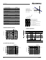
GEBRUIKERSHANDLEIDING / USERS MANUAL
BETRIEBSANLEITUNG / MODE D’EMPLOI
MASS 12/30-2, 24/15-2, 24/25-2
battery charger
1
General information . . . . . . . . . . . . . . . . . . . . . . . . . . . . . . . . . . . . . . . . . . . . . . . . . . . . . . . . . . .10
2
Safety guidelines & measures . . . . . . . . . . . . . . . . . . . . . . . . . . . . . . . . . . . . . . . . . . . . . . . . . . .10
3
Technical data . . . . . . . . . . . . . . . . . . . . . . . . . . . . . . . . . . . . . . . . . . . . . . . . . . . . . . . . . . . . . . .11
4
Technology . . . . . . . . . . . . . . . . . . . . . . . . . . . . . . . . . . . . . . . . . . . . . . . . . . . . . . . . . . . . . . . . . 11
5
Installation . . . . . . . . . . . . . . . . . . . . . . . . . . . . . . . . . . . . . . . . . . . . . . . . . . . . . . . . . . . . . . . . . .12
6
Operation . . . . . . . . . . . . . . . . . . . . . . . . . . . . . . . . . . . . . . . . . . . . . . . . . . . . . . . . . . . . . . . . . . .14
7
Batteries . . . . . . . . . . . . . . . . . . . . . . . . . . . . . . . . . . . . . . . . . . . . . . . . . . . . . . . . . . . . . . . . . . .14
8
Trouble shooting . . . . . . . . . . . . . . . . . . . . . . . . . . . . . . . . . . . . . . . . . . . . . . . . . . . . . . . . . . . . . .15
9
Maintenance . . . . . . . . . . . . . . . . . . . . . . . . . . . . . . . . . . . . . . . . . . . . . . . . . . . . . . . . . . . . . . . .16
10
EC declaration of conformity . . . . . . . . . . . . . . . . . . . . . . . . . . . . . . . . . . . . . . . . . . . . . . . . . . . . .16
11
Data sheets . . . . . . . . . . . . . . . . . . . . . . . . . . . . . . . . . . . . . . . . . . . . . . . . . . . . . . . . . . .Apendix A
12
Installation sheet . . . . . . . . . . . . . . . . . . . . . . . . . . . . . . . . . . . . . . . . . . . . . . . . . . . . . . .Apendix B
MASTERVOLT
Snijdersbergweg 93, 1105 AN Amsterdam, The Netherlands
Tel. +31-20-3422100 / Fax +31-20-6971006
V1. September 1999
GENERAL INFORMATION
1
/
SAFETY GUIDELINES EN MEASURES
GENERAL INFORMATION
GARANTEE SPECIFICATIONS
Mastervolt quarantees the performance of this Mass charger according to the specifications given in the data
sheets, if installed and used as described in this manual.
Should work take place, which is not in accordance with
the guidelines, instructions and specifications contained
in this user's manual and the supplementary installation
manual, then damage may occur and/or the unit may not
fulfil its specifications. All of these matters may mean that
the guarantee may become invalid.
The guarantee period is two years.
2
QUALITY
During their production and prior to their delivery, all of our
units are exhaustively tested and inspected.
LIABILITY
Mastervolt can accept no liability for:
• damage due to use of the battery charger;
• possible errors in the manual and the results thereof.
SAFETY GUIDELINES & MEASURES
USE FOR INTENDED PURPOSE
The battery charger is contructed as per the applicable
safety-technical guidelines. Use the battery charger only:
2
Check the wiring at least once a year. Defects such as
loose connections, burned cables etc. must be corrected immediately.
• for the charging of lead acid batteries and the supply of
users attached to these batteries, in permanent systems;
3
Do not work on the charger or the system if it is still
connected to a current source. Only allow changes in
your electrical system to be caried out by qualified
electricians.
4
Connection and protection must be done in accordance with local standards.
5
Before opening the cabinet of the charger, switch off
the 230V mains and remove the charger fuse.
• connected to a dedicated double pole circuit breaker
(MCB);
• with a fuse, protecting the wiring between charger output and battery;
• in a technical correct condition;
• in a closed, well-ventilated room, protected against rain,
moist, dust and not condensing circumstances.
Never use the battery charger at locations
where there is danger of gas- or dust explosion!
MAINTENANCE & REPAIR
If the battery charger is switched off during maintenance
and/or repair activities, it should be secured against unexpected and unintentional switching on:
• switch off the AC circuit breaker;
Use other than as mentioned under 2 is not considered to
be consistent with the intended purpose. Mastervolt is not
liable for any damage resulting from the above.
SAFETY
1
Use only fuses with the prescribed current level:
• AC supply fuse not greater than is required for the
current consumption;
• disconnect the charger;
• switch off the connection with the batteries or remove
the charger fuse;
• be sure that third parties cannot reverse the measures
taken.
If such are required, use only original spare parts.
• The charger fuse must be large enough for the maximal charger current and small enough to protect
the charger‘s output cables.
10
August 1999 / MASS battery charger / EN
TECHNICAL DATA
/ TECHNOLOGY
3 TECHNICAL DATA
GENERAL
Model
Function apparatus
Manufacturer
MASS 12/30-2
battery charger/rectifier
Mastervolt, Amsterdam
MASS 24/15-2
MASS 24/25-2
INPUT
Voltage
Frequency
Current
Power factor
Efficiency
230V, -10% +15%
50/60 Hz, ± 5 Hz
2.5A
1
88%
230V AC, -10% +15%
50/60 Hz, ± 5 Hz
2.5A
1
88%
230V, -10% +15%
50/60 Hz, ± 5 Hz
3.6A
1
88%
OUTPUT
Output voltage
Output current (total max)
Outputs
Charge characteristic
Kind of batteries
Charge voltages (depending of phase)
Ripple voltage
Current
Short circuit current
Polarity control.
nominal: 12V DC
nominal: 24V DC
30A
15A
2 (1x30A max. 1xA max.)
2 (1x15A max. 1x3A max.)
three-step, fully automatic, IUoUo
open and sealed lead acid batteries / wet or gel
14.4V-13.25V
28.7V-26.5V
max. 100mV rms, resistive load, full power
30 Amps
15 Amps
30 Amps
15 Amps
polarity protected by means of a breaker
nominal: 24V DC
25A
2 (1x25A max. 1x3A max.)
28.7V-26.5V
25 Amps
25 Amps
ENVIRONMENTAL CHARACTERISTICS
Operating ambient temperature
-20 to +40°C; 100% output power
Cooling
forced, by means of a fan with variable speed
Humidity
max. 95% RV, not condensing
ENCLOSURE
Dimensions (hxwxd)
Protection level
Weight
Safety
4
325x220x111 mm
IP 22
2.6 kg
IEC 335-2-29
TECHNOLOGY
INTRODUCTION
The MASS battery charger is a fully automatic high-efficient battery charger/rectifier,developed and produced by
Mastervolt Amsterdam. The MASS series goes with a
family of advanced quality battery chargers. Mastervolt
distributes these products worldwide. The battery charger
posseses an outstanding charging technique in order to
charge batteries rapidly, safely and in the same time supply the connected consumers. In addition, the charger is
secured against short circuit, overload and high temperatures in an industrial enviroment.
THEORY OF OPERATION
The MASS battery charger has a three-step charge
characteristic (see fig. 1).
EN / MASS battery charger / August 1999
Fig. 1
Example:
Charge caracteristic MASS 12/15. (For other
models V/A according to data sheets).
11
TECHNOLOGY
/
INSTALLATION
Phase 1: Main charge (“BULK”)
The first step “BULK” starts after switching on the MASS
charger. In this phase, the charger supplies the maximum
current until the battery reaches 14.40V. The battery is
now 80% charged. When the battery reaches this limitation area the charge current wil decrease. Bulk duration is
maximum 6 hours, depending on the battery’s condition
and charge rate. The yellow “bulk” LED on the front panel
will light up during this phase.
Phase 2: “ABSORPTION”
The second step “ABSORPTION” begins automatically
with a voltage of 14.25V. The current consumption in the
absorption mode is depending on the capacity of the
batteries and will decrease slowly. The charger remains in
this “absorption” phase untill the charge current drops for
a periode of 15 minutes below 2.5A. If the charge current
will not drop below 2.5A, a clock will switch the “absorption” mode off after 6 hours. During the absorption phase
the yellow “ABSORPTION” LED on the front panel will
light up.
Phase 3: Trickle charge (“FLOAT”)
The third stage, “FLOAT”, starts when the “absorption”
phase has been completed. In the “float” mode, the charger automatically switches back to a lower output voltage
of 13,25V. This voltage is sufficient to maintain the battery
at a 100% charge. During this phase, the capacity of the
charger can be entirely used for the supply of the users
connected to the battery. During this mode the yellow
“float” LED will light up. If necessary the charger automatically switches back to the “absorption” mode.
Current consumption from mains or generator
The charger produces no phase shift, because the input
current follows the AC voltage waveform so a power
factor of 1.0 or “unity” is achieved. The shape of the input
current waveform is the same as the input voltage e.g.
sinusoïdal. Therefore the input current is very low compared to conventional chargers.
The charger has been programmed in such a way that a
seperate sense connection to the battery is not necessary.
CHARGING TWO OR MORE BATTERIES VIA
ONE OUTPUT
If two or more batteries need to be charged at the same
time and output, a battery isolator should be used. The
battery isolator divides the various battery sets from one
other, in order to avoid one set discharging the other. Because there is always a voltage drop across the isolator of
0,7V the output voltage needs to be compensated. You
can compensate this voltage drop by removing the “diode
compensation” jumper on the front panel.
CHARGING A CRANKING BATTERY
In certain situations, it may occur that in addition to the
main battery(ies) a cranking battery with the same voltage
is used. The battery charger can charge a cranking battery at the same time as the main battery, by using the 3A
output.
The second output has the same output voltage
as the main output, 3 Amps maximal !
THE BATTERY CHARGER AS FLOAT CHARGER
It is possible to use the charger as a “trickle” charger. The
charger then supplies a constant output voltage of 13.25V
(26.5V). For this mode you can remove a jumper on the
front.
SELECTION WET OR GEL BATTERIES
The optimal charge voltage for a wet lead acid battery differs from the gel battery. Therefore it is possible to switch
over to a higher float voltage (13.8V for 12V and 27.6V for
24V) necessary for gel batteries. You increase this output
voltage by removing a jumper on the front panel.
5
Low ripple on output
The charger has a very low ripple on the output, which prevents interference in the DC circuit. The ripple is less than
100 mV with maximum output current.
Automatic compensation of charge voltage with
battery temperature
If the temperature sensor is connected the MASS charger
will charge its output voltage -30mV/°C (12V) or -60mV/°C
(24V). The temperature sensor should give a good interpretation of the battery temperature.
Automatic voltage sense compensation
The charger compensates automatically for the normal
voltage drop across the cable connection to the battery.
12
INSTALLATION
Install the MASS battery charger in a dry, well ventilated
area, as close as possible to the batteries. Although the
battey charger has a high efficiency, some heat will be
produced. This heat will be discharged by a fan with variable speed. At installation of the battery charger be sure
that:
• the air flow is not obstructed;
• no water and/or dust can enter the cabinet.
MOUNTING THE MASS CHARGER
The charger can be either horizontal or vertical mounted.
We recommend vertical, because the heat convection is
from bottom to top.
August 1999 / MASS battery charger / EN
INSTALLATION
WIRING AND CONNECTIONS
When connecting any auxiliary equipment and/or a battery isolator, proceed as follows:
• switch off the charger;
• switch off the AC mains or generator supply;
• isolate the DC distribution from the battery.
Steps:
1
2
3
Battery wires
Keep the cable connection between charger and battery
as short as possible. If possible use coloured battery
cables. I f this is not possible, mark the plus and the minus
cables with coloured insulating tape, e.g. red for plus and
blue for minus. Use the following diameters:
lenght up to 3 meter
6 qmm
lenght above 3 meter
10 qmm
Connection of main batteries
The minus cable (blue) on the -battery (minus connection)
of the battery charger. The plus cable (red) on the + main
battery (plus-connection) of the charger.
The other side of the cable has to be connected to the
battery or the DC distributor. The minus cable (blue) on
the min-connection of the battery or DC divider. The plus
cable (red) on the plus-connection of the battery or DC
divider.
Reversing the plus and the minus wil blow the
fuse near to the minus connector ( the red LED
above the fuse wil light up ). Before you replace
the fuse check the polarity of the connections. Replace
the fuse only for a 20A fuse.
Too thin cables and/or loose connections can
cause dangerous overheating of the cables and/
or terminals. Therefore tighten all connections
properly, in order to limit as much as possible transition
resistance, and use the battery cables with the correct
diameter.
Battery isolator
If one or more batteries or battery sets must be charged
at the same time via one output, a battery isolator should
be used. A battery isolator isolates the different battery
sets from one another, in order to prevent one discharging
the other. A consequence of the battery isolator is a voltage drop of 0.7 Volt. This voltage drop can be compensated by removing a jumper on the front panel of the charger.
Choose isolator type:
2 battery set
MV 702
3 battery set
MV 703
For proper installation, see the connection diagram included with the battery isolator.
EN / MASS battery charger / August 1999
4
Check if the charger, the main supply and the DC
divider are switched off.
Connect the battery isolator(s) using cables with the
same diameter as the battery cables.
Compensate the voltage drop over these diodes by removing the “diode compensation” jumper on the front
of the charger.
Switch the charger on.
Connection of cranking battery (3A output)
The distance between charger and cranking battery determines the required, minimal cable diameter. For cable
lenghts up to 6 meters 2,5 qmm must be used. When
using long thin cables, it will take proportionately longer
before a crancking battery is entirely charged. Therefore
use, for longer distances, a larger diameter. The maximal
charging current for the cranking battery is 3A. The charging current for the main battery will in this case be 3A
lower.
• Connect the minus of the cranking battery to the minus
of the main battery.
• Connect the plus of the cranking battery to the “BAT2”
plus terminal of the charger.
AC power supply
Check the voltage of your mains source or generator. This
must be between 190 and 250 VAC.
Connect the mains cable on one side on the MASS
charger and the opposite side to the mains or generator.
ACCESSORIES
When connecting accessories, first switch the charger
„OFF” and disconnect from AC.
Temperature sensor
Mount the sensor at a location that gives a good indication
of the battery temperature. Plug the connection cable into
one of the input jacks of the charger.
Basic remote panel
Plug the connection cable into the analog input jack.
Standard remote panel
Plug the connection cable into the digital input jack.
The communication protocol is based on quasi RS 232.
Adjustment Interface & advanced remote panel
Plug the connection cable into the digital input jack.
The communication protocol is based on quasi RS 232.
ADJUSTMENTS
On the front of the charger you find three jumpers, each
for a specific application. You can easily remove the jumpers with a pincet or a small pincer.
13
INSTALLATION
/
OPERATION
/
USING THE CHARGER WITH YOUR BATTERIES
Switching off:
The IVO charger will be switched off by the OFF switch.
7
Forced float
For industrial applications only.
Gel/wet battery
By removing this jumper the output will be a constant
“trickle charge” voltage of 13,8V.
Diode compensation
By removing this jumper the output voltage will be increased
with 0,7 Volt.
6
USING THE CHARGER WITH YOUR
BATTERIES
CHARGING EFFICIENCY
For a good performance your batteries should not be
discharged below 30-40% of their capacity. Therefore always start charging at this level.
As in marine and mobile systems often a limited charging
time is desired, batteries are with generator use charged
up to 85-90%. Charging up to 100% would take too long.
This means that normally about 50% of the theoretical
battery capacity can be used.
In case a mains connection is present, charging time is
less important. Then charging up to 100% is advised.
OPERATION
TIPS TO INCREASE THE BATTERY LIFETIME:
1
2
3
Check if the charger is „OFF”.
Connect DC output with batteries or place fuse.
Switch on AC source.
Switching on:
The MASS charger will be switched on by the ON switch.
One of the front LEDS will light up now and the charging
starts immediately.
FLOAT:
The battery charger is
in a “trickle charge” mode, batteries are 100%
charged.
ABSORPTION:
The batteries are still
charging, charge level
is approx. 80%.
float charge 80 - 100 %
absorption
50 %
bulk charge - on
• Charge the battery immediately after a consistent deep
discharge.Especially at high environment temperatures,
sulfating occurs very fast. If the state of sulfating is not
too bad, the battery will regain a part of its capacity after a number of charge/recharge cycles.
CHARGE INDICATOR
INDICATOR LIGHTS
• Install the batteries at a cool place. The acid in the batteries will damage the plates in a high temperature environment. A normal life time of 5 year at 20°C, will go
down to 2.5 years at 30°C.
off
on
BULK:
The
the
the
less
charger supplies
maximal voltage,
battery charge is
than 80%.
charge failure
MASS
AUTOMATIC
BATTERY CHARGER
14
August 1999 / MASS battery charger / EN
TROUBLE SHOOTING
8
TROUBLE SHOOTING
Malfunction
Possible cause
What to do
No output voltage and/or current
No AC mains or fuse blowes
Check fuse, replace if necessary.
Mains or generator output too low
Check input voltage, must be between
190 and 260V (nominal 230V).
Battery load consumes more than the
charger can supply, the battery voltage
cannot increase more
Reduce the battery load taken from
batteries.
Batteries not 100% charged
Measure the battery voltage after a
while, this will be higher.
Batteries almost fully charged
Check if the charger is in the absorption mode. In this mode, the charge
current will slowly decrease.
High ambient temperature
If the ambient temperature is more than
40°C, the maximum charge current
automatically will be reduced.
Mains too low
When the mains is lower than 190V,
the charger will regulate the current
down.
Batteries not fully charged
Charge current too low
Current to load too high
Charge time too short
Battery temperature too low
Defective battery (short circuit in cell)
Defective battery charger
See “charge current too low”;
Decrease the battery load;
Increase type of charger;
Use temperature sensor;
Replace the battery;
Check the charger.
Battery very fast empty
Battery capacity reduced because:
• wastage
• sulphating/stagnation
Output voltage too low but
charger supplies max. current
Charge current too low
Batteries are warm/gassing
Defective batteries (short circuit in cell)
Battery temperature too high
Charge voltage too high
Replace the batteries;
Charge/discharge for several times, this
might help, otherwise replace batteries.
Replace batteries;
Use temperature sensor;
Check jumper ‘battery isolator’
on front panel.
If you cannot solve the problem with this fault finding table, contact your Mastervolt Service Centre.
For a detailed distributor list, please contact our main office in Amsterdam, tel. +31-20-3422100.
EN / MASS battery charger / August 1999
15
MAINTENANCE
9
/
EC DECLARATION
MAINTENANCE
The battery charger requires no specific maintenance. For
a reliable and optimal function of the MASS battery charger only the following is required:
• Check at least ones a year the wire and cable connections (loosen joints etc.).
• Keep the MASS charger dry, clean and in a dust-free
area, in order to ensure a good heat discharge.
10
EC DECLARATION OF CONFORMITY
Manufacturer:
Address:
Herewith declares that:
Product:
Model:
MASTERVOLT
Snijdersbergweg 93
1105 AN AMSTERDAM Z.O.
The Netherlands
MASS
MASS
MASS
MASS
battery charger
12/30-2
24/15-2
24/25-2
Is in conformity with the provision of the EC EMC directive 89/336/EEC and
amendments 92/31/EEC and 93/68/EEC.
The following harmonized standards have been applied:
Generic emission standard
EN 50081-1:1992
Generic immunity standard
EN 50082-1:1992
Amsterdam,
Dr. F.J. ter Heide,
Managing director MASTERVOLT
16
August 1999 / MASS battery charger / EN
APENDIX A & B
MASS 12/30-2, 24/15-2, 24/25-2
battery charger
MASTERVOLT
Snijdersbergweg 93, 1105 AN Amsterdam, The Netherlands
Tel. +31-20-3422100 / Fax +31-20-6971006
V1. September 1999
34
DATA SHEETS
11
DATA SHEETS MASS 12/30-2
MAIN INFORMATION
Design
Manufacturer
Model / name
Product
Article no
Colour
:
:
:
:
:
:
Weight excl. packing
Shipping weight
Cabinet typ
Dimensions
Carton dimensions
Type of packing
Available
Availability
:
:
:
:
:
:
:
:
by MASTERVOLT
ISO 9001 certified
MASS 12/30-2
battery charger/rectifier
04-00-10300
• RAL 5021, wasserblau
• RAL 7037, grey
2.6 kg
4 kg
MASS 1 cabinet
hxwxd. 325 x 220 x 111 mm
hxwxd. 350 x 250 x 160 mm
carton recycable
230V / 50-60Hz
normally from stock, from July ‘99 onwards
Mass 12/30-2 battery charger/rectifier, art.no 04-00-10300,
in new ‘high tech’ enclosure.
Return Amps
Min. Absorption time
Max. Bulk/abs. time
Return new cycle voltage
Temperature compensation
Voltage sense
Ripple voltage
Voltage accurancy
Current accurancy
Maximum output
:
:
:
:
:
:
:
:
:
:
DC leakage drain
Number of outputs
AC/DC connections
:
:
:
Jumper selections
:
Remote indication
Remote connection
Temperature connection
Smart controls
:
:
:
:
Apendix A
charging of 12V lead acid batteries and power simultanously loads
230V AC, 1ph, 3wire, 50/60 Hz
190..250V, 50/60 Hz, ± 5%
0..250V, 33-80 Hz
at 230V AC: 2.5A
no inrush current, soft start, according to IEC 1003-3
1, power factor controlled, IEC 555-2
550 Watt
> 88%
nominal 12V DC
nominal 30 Amps
three-step, fully automatic, IUoUo, programmable
float charge 80 - 100 %
open & sealed lead acid batteries
• bulk voltage 14.40V
• absorption 14.25V
• wet float 13.25V • gel float 13.8V
2.5A
absorption
50 %
15 minutes
6 hours
12.8V, delay 30 seconds
bulk charge - on
30 mV/°C, by temperature sensor
fully automatic compensation
max. 100mV rms, resistive load, full power
voltage ± 2%
off
current ± 3%
• 30 Amps at 14.25 Volt at 25°C ambient
on
• 30 Amps at 13.25V at 40°C ambient
< 10 mA
charge failure
one main outputs and one 3 Amps Slave Charger
internal,
min. AC cable size: 2.5 mm2 / min. DC cable size: 16 mm2
• gel/wet battery selection
• forced to float
AUTOMATIC
• battery isolator compensation
status bulk, absorption, float
BATTERY CHARGER
by telephone plug-in jack - RJ45
Standard control on unit.
by telephone plug-in jack - RJ45
QRS232 output by telephone plug - RJ45
CHARGE INDICATOR
TECHNICAL SPECIFICATIONS
Function apparatus
:
Nominal input voltage
:
Input voltage range full specs :
Input voltage range no-defects :
Input current
:
Inrush current
:
Power factor
:
Max. input power
:
Efficiency
:
Output voltage
:
Output current
:
Charge characteristic
:
Kind of batteries
:
Charge voltage 25°C
:
MASS
35
DATA SHEETS
TECHNICAL SPECIFICATIONS
Short circuit proctection
Reverse polarity protection
Over heat
: yes, reduced output max. 30 Amps
: yes, by internal fuses
: yes, derating output and shut off by 80°C temperature on heatsink
Storage temperature
Operating ambient temperature
Humidity
Vibration
Cooling
Forced cooling
Environmental protection
:
:
:
:
:
:
:
Reliability/life time
: • MTBF 30.000 hours
• 1/4 life time period, Uin = 207V AC, Uout = 14,25, Iout = 30 Amps at Tamb 40°C
• 3/4 life time period, Uin = 207V Ac, Uout = 13,25, Iout = 30 Amps at Tamb 25°C
-25°C to 80°C
-20°C to 40°C, derating with 2.5% / °C > 40°C
maximum 95%, not condensing
according IEC 68-2-6
mix of conventional and forced air cooling
by one variable speed maintenance free DC fan
IP21
ELECTRO MAGNETIC COMPATBILITY
Electro Magnetic Emission : better than EN 50081-1 (gen. emmission standard, scope; residiential, commercial & light industry)
Electro Magnetic Immunity : better than EN 50082-1 (gen. emmission standard, scope; residiential, commercial & light industry)
Safety
: according to IEC 335-2-29, polarity protected by means of a breaker, short break
WHAT TO DO IN CASE OF A DEFECT?
✔ Consult factory in Amsterdam, tel. +31-20-3422100, or your local Repair Center.
200
58
48
83
41
101
111.2
6
10
Main PCB of the MASS 12/30-2.
10
220
Dimensions of the new cabinet and PCB.
COMPLIANCES
• CE:
Is in conformity with the provision of the EC EMC directive 89/336/EEC and amandments 92/31/EEC, 93/68/EEC.
The following harmonized standards have been applied: • Generic emission standard : EN 50081-1:1992
• Generic immunity standard : EN 50082-1:1992
• LLOYDS, DNV, ABS:
MASTERVOLT has constructed this product for rugged circumstances in professional or leisure situations.
This product can be type-approved individually. Price approx. US $ 1500 per certification.
• MANUFACTURED UNDER ISO 9001.
36
Apendix A
DATA SHEETS
Main PCB of the MASS 12/30-2.
New ‘high tech’ enclosure.
ACCESSORIES
Article no
04-15-00100
--04-15-00300
--00-17-05000
--
& REMOTES
description
basic remote control
standaard remote contol
advanced remote control
MASS 1 temperature sensor
MASS 1 cable set
MASS 1 remote cable set
Adjustment Interface
Smart alarm control box
LED’s
LED’s current control
display with owner’s settings
SERVICE INFORMATION
Article no
description
-sub assy, main PCB board
-complete aluminium heatsink
-cover module
-connection module
-front indicator module
-installation blocks
Adjustment Interface, art. no 02-17-05000.
The below mentioned data can be adjusted with this
digital instrument:
• adjustment charge voltage (e.g. traction)
• ‘return’ Amps etc.
OPERATING PRINCIPLE
Fully automatic power factor switch mode battery charger, suitable as power supply using a separate non-isolated pre regulator
boost converter for power factor correction, followed by a double forward converter controlled by a combination of analogue
hardware and microprocessor control.
AC input
DC output
Aux. power supply
PFC
HARDWARE CONTROL
SOFTWARE CONTROL
remote
Apendix A
DC/DC
select
RS232
37
DATA SHEETS
• Temperature variation
5.0 mV/°C per cell
• Reference voltage 25°C
• Battery charging is not allowed
above +50°C and under -20°C
• 12 Volt 30 mV/°C
• 24 Volt 60 mV/°C
5.0 mV/°C
Uref 25°C
flo
at
ge
l/w
et
ba
tte
dio
ry
de
co
m
pe
ns
at
ion
Setpoint
30
sec.
30
mV/C
30
sec.
12.80 V
360
min.
15
min.
2.5
Amps
30
Amps
14.40 V
14.25 V
13.25 V
13.25 V
550
mV
600
mV
15.00 V
14.50 V
10.00 V
11.00 V
30
sec.
ed
Set points register
Min. bulk time
Temperature variation
Return to bulk time
Return to bulk voltage
Max. bulk/abs time
Min. abs time
Return Amps
Max. charge current
Bulk voltage
Abs voltage
Float voltage
Forced to float voltage
Gel voltage setting
Diode compensation setting
DC high alarm on
DC high alarm off
DC low alarm on
DC low alarm off
Alarm delay time
for
c
1
2
3
4
5
6
7
8
9
10
11
12
13
14
15
16
17
18
19
standard IUU characteristic
IUU char. increased with 0.6V
IUU char. high float level
IUU char. high float, increased with 0.6V
IU char. low float level
IU char. low float, increased with 0.6V
IU char. high float level
IU char. high float, increased with 0.6 V
TEMPERATURE COMPENSATED CHARGING
CHARGING CHARACTERISTICS
25°C reference
temperature
charging voltage in V
15.0
14.5
absorption
14.0
13.5
float
13.0
12.5
12.0
-30
-20
-10
0
10
20
30
40
50
60
battery temperature in °C
min. bulk time
MAX. BULK
BULK TIME
TOTAL CHARGE TIME CYCLE
min. abs time
return to bulk time
ABS TIME
FLOAT TIME
NEW CYCLE
MAX. OUTPUT VERSUS INPUT VOLTAGE
25°C reference
temperature
25°C reference
temperature
Tamb= 25°C
35
14.25V
30
230V model
25
20
charging voltage in V
current in Amps
40
Tamb= 40°C
15
80
100
120
140
160
180
200
220
240
260
input voltage
38
0
20
30
40
output current in Amps
Apendix A
DATA SHEETS
DATA SHEETS MASS 24-15-2
MAIN INFORMATION
Design
Manufacturer
Model / name
Product
Article no
Colour
:
:
:
:
:
:
Weight excl. packing
Shipping weight
Cabinet type
Dimensions
Carton dimensions
Type of packing
Available
Availability
:
:
:
:
:
:
:
:
by MASTERVOLT
ISO 9001 certified
MASS 24/15-2
battery charger/rectifier
04-00-20150
• RAL 5021, wasserblau
• RAL 7037, grey
2.6 kg
4 kg
MASS 1 cabinet
hxwxd. 325 x 220 x 111 mm
hxwxd. 350 x 250 x 160 mm
carton recycable
230V / 50-60Hz
normally from stock, from July ‘99 onwards
TECHNICAL SPECIFICATIONS
Function apparatus
:
Nominal input voltage
:
Input voltage range full specs :
Input voltage range no-defects :
Input current
:
Inrush current
:
Power factor
:
Max. input power
:
Efficiency
:
Output voltage
:
Output current
:
Charge characteristic
:
Kind of batteries
:
Charge voltage 25°C
:
Return Amps
Min. Absorption time
Max. Bulk/abs. time
Return new cycle voltage
Temperature compensation
Voltage sense
Ripple voltage
Voltage accurancy
Current accurancy
Maximum output
:
:
:
:
:
:
:
:
:
:
DC leakage drain
Number of outputs
AC/DC connections
:
:
:
Jumper selections
:
Remote indication
Remote connection
Temperature connection
Smart controls
:
:
:
:
Apendix A
Mass 24/15-2 battery charger/rectifier, art.no 04-00-20150,
in new ‘high tech’ enclosure.
charging of 24V lead acid batteries and power simultanously loads
230V AC, 1ph, 3wire, 50/60 Hz
190..250V, 50/60 Hz, ± 5%
0..250V, 33-80 Hz
at 230V AC: 2.5A
no inrush current, soft start, according to IEC 1003-3
1, power factor controlled, IEC 555-2
550 Watt
> 88%
nominal 24V DC
float charge 80 - 100 %
nominal 15 Amps
three-step, fully automatic, IUoUo, programmable
open & sealed lead acid batteries
• bulk voltage 28.7V
• absorption 28.5V
absorption
50 %
• wet float 26.5V
• gel float 27.6V
1.25A
15 minutes
bulk charge - on
3 hours
25.6V, delay 30 seconds
60 mV/°C, by temperature sensor
fully automatic compensation
off
max. 100mV rms, resistive load, full power
voltage ± 2%
on
current ± 3%
• 15 Amps at 28.5 Volt at 25°C ambient
charge failure
• 15 Amps at 26.5V at 40°C ambient
< 5 mA
one main outputs and one 3 Amps Slave Charger
internal,
min. AC cable size: 2.5 mm2 / min. DC cable size: 16 mm2
AUTOMATIC
• gel/wet battery selection
• forced to float
BATTERY CHARGER
• battery isolator compensation
Standard control on unit.
status bulk, absorption, float
by telephone plug-in jack - RJ45
by telephone plug-in jack - RJ45
QRS232 output by telephone plug - RJ45
CHARGE INDICATOR
11
MASS
39
DATA SHEETS
TECHNICAL SPECIFICATIONS
Short circuit proctection
: yes, reduced output max. 15 Amps
Reverse polarity protection
: yes, by internal fuses
Over heat
: yes, derating output and shut off by 80°C temperature on heatsink
Storage temperature
Operating ambient temperature
Humidity
Vibration
Cooling
Forced cooling
Environmental protection
:
:
:
:
:
:
:
-25°C to 80°C
-20°C to 40°C, derating with 2.5% / °C > 40°C
maximum 95%, not condensing
according IEC 68-2-6
mix of conventional and forced air cooling
by one variable speed maintenance free DC fan
IP21
Reliability/life time
: • MTBF 30.000 hours
• 1/4 life time period, Uin = 207V AC, Uout = 28.5, Iout = 15 Amps at Tamb 40°C
• 3/4 life time period, Uin = 207V Ac, Uout = 26.5, Iout = 15 Amps at Tamb 25°C
ELECTRO MAGNETIC COMPATBILITY
Electro Magnetic Emission : better than EN 50081-1 (gen. emmission standard, scope; residiential, commercial & light industry)
Electro Magnetic Immunity : better than EN 50082-1 (gen. emmission standard, scope; residiential, commercial & light industry)
Safety
: according to IEC 335-2-29, polarity protected by means of a breaker, short break
WHAT TO DO IN CASE OF A DEFECT?
✔ Consult factory in Amsterdam, tel. +31-20-3422100, or your local Repair Center
200
58
48
83
41
101
111.2
6
10
Main PCB of the MASS 24/15-2.
10
220
Dimensions of the new cabinet and PCB.
COMPLIANCES
• CE:
Is in conformity with the provision of the EC EMC directive 89/336/EEC and amandments 92/31/EEC, 93/68/EEC.
The following harmonized standards have been applied:
• Generic emission standard
: EN 50081-1:1992
• Generic immunity standard
: EN 50082-1:1992
• LLOYDS, DNV, ABS:
MASTERVOLT has constructed this product for rugged circumstances in professional or leisure situations.
This product can be type-approved individually. Price approx. US $ 1500 per certification.
• MANUFACTURED UNDER ISO 9001.
40
Apendix A
DATA SHEETS
Main PCB of the MASS 24/15-2.
New ‘high tech’ enclosure.
ACCESSORIES & REMOTES
Article no
description
04-15-00100
--04-15-00300
--00-17-05000
--
basic remote control
LED’s
standaard remote contol
LED’s current control
advanced remote control
display with owner’s settings
MASS 1 temperature sensor
MASS 1 cable set
MASS 1 remote cable set
Adjustment Interface
Smart alarm control box
SERVICE INFORMATION
Article no
description
-------
sub assy, main PCB board
complete aluminium heatsink
cover module
connection module
front indicator module
installation blocks
Adjustment Interface, art. no 02-17-05000.
The below mentioned data can be adjusted with this
digital instrument:
• adjustment charge voltage (e.g. traction)
• ‘return’ Amps etc.
OPERATING PRINCIPLE
Fully automatic power factor switch mode battery charger, suitable as power supply using a separate non-isolated pre regulator
boost converter for power factor correction, followed by a double forward converter controlled by a combination of analogue
hardware and microprocessor control.
AC input
DC output
Aux. power supply
PFC
HARDWARE CONTROL
SOFTWARE CONTROL
remote
Apendix A
DC/DC
select
RS232
41
DATA SHEETS
Setpoint
30
sec.
60
mV/C
30
sec.
25.60 V
360
min.
15
min.
1.25 Amps
15
Amps
28.70 V
28.50 V
26.50 V
26.50 V
1.10 V
600
mV
30
V
29
V
20
V
22
V
30
sec.
• Temperature variation
5.0 mV/°C per cell
• Reference voltage 25°C
• Battery charging is not allowed
above +50°C and under -20°C
• 12 Volt 30 mV/°C
• 24 Volt 60 mV/°C
5.0 mV/°C
flo
at
ge
l/w
et
ba
tte
dio
ry
de
co
m
pe
ns
at
ion
Uref 25°C
ed
Set points register
Min. bulk time
Temperature variation
Return to bulk time
Return to bulk voltage
Max. bulk/abs time
Min. abs time
Return Amps
Max. charge current
Bulk voltage
Abs voltage
Float voltage
Forced to float voltage
Gel voltage setting
Diode compensation setting
DC high alarm on
DC high alarm low
DC low alarm on
DC l ow alarm off
Alarm delay time
for
c
1
2
3
4
5
6
7
8
9
10
11
12
13
14
15
16
17
18
19
standard IUU characteristic
IUU char. increased with 0.6V
IUU char. high float level
IUU char. high float, increased with 0.6V
IU char. low float level
IU char. low float, increased with 0.6V
IU char. high float level
IU char. high float, increased with 0.6 V
TEMPERATURE COMPENSATED CHARGING
CHARGING CHARACTERISTICS
25°C reference
temperature
30
29
charging voltage in V
30
28
29
27
absorption
26
28
25
27
24
float
26
25
24
-30
-20
-10
0
10
20
30
40
50
60
min. bulk time
MAX. BULK
BULK TIME
TOTAL CHARGE TIME CYCLE
battery temperature in °C
min. abs time
ABS TIME
ABS TIME
return to bulk time
FLOAT TIME
NEW CYCLE
MAX. OUTPUT VERSUS INPUT VOLTAGE
25°C reference
temperature
25°C reference
temperature
30
29
15
14.25V
230V model
10
charging voltage in V
current in Amps
20
Tamb= 25°C
28
Tamb= 40°C
27
26
25
24
80
100
120
140
160
180
200
220
240
260
input voltage
42
0
7.5
15
output current in Amps
Apendix A
DATA SHEETS
11
DATA SHEETS MASS 24/25-2
MAIN INFORMATION
Design
Manufacturer
Model / name
Product
Article no
Colour
:
:
:
:
:
:
Weight excl. packing
Shipping weight
Cabinet type
Dimensions
Carton dimensions
Type of packing
Available
Availability
:
:
:
:
:
:
:
:
by MASTERVOLT
ISO 9001 certified
MASS 24/25-2
battery charger/rectifier
04-00-20250
• RAL 5021, wasserblau
• RAL 7037, grey
2.6 kg
4 kg
MASS 1 cabinet
hxwxd. 325 x 220 x 111 mm
hxwxd. 350 x 250 x 160 mm
carton recycable
230V / 50-60Hz
normally from stock, from July ‘99 onwards
Mass 24/25-2 battery charger/rectifier, art.no 04-00-20250,
in new ‘high tech’ enclosure.
Return Amps
Min. Absorption time
Max. Bulk/abs. time
Return new cycle voltage
Temperature compensation
Voltage sense
Ripple voltage
Voltage accurancy
Current accurancy
Maximum output
:
:
:
:
:
:
:
:
:
:
DC leakage drain
Number of outputs
AC/DC connections
:
:
:
Jumper selections
:
Remote indication
Remote connection
Temperature connection
Smart controls
:
:
:
:
Apendix A
charging of 24V lead acid batteries and power simultanously loads
230V AC, 1ph, 3wire, 50/60 Hz
190..250V, 50/60 Hz, ± 5%
0..250V, 33-80 Hz
at 230V AC: 3.6A
no inrush current, soft start, according to IEC 1003-3
1, power factor controlled, IEC 555-2
800 Watt
> 88%
nominal 24V DC
nominal 25 Amps
three-step, fully automatic, IUoUo, programmable
float charge 80 - 100 %
open & sealed lead acid batteries
• bulk voltage 28.7V • absorption 28.5V
• wet float 26.5V
• gel float 27.6V
absorption
50 %
1.25A
15 minutes
6 hours
25.6V, delay 30 seconds
bulk charge - on
60 mV/°C, by temperature sensor
fully automatic compensation
max. 100mV rms, resistive load, full power
off
voltage ± 2%
current ± 3%
on
• 25 Amps at 28.5 Volt at 25°C ambient
• 25 Amps at 26.5V at 40°C ambient
< 5 mA
charge failure
one main outputs and one 3 Amps Slave Charger
internal,
min. AC cable size: 2.5 mm2 / min. DC cable size: 16 mm2
• gel/wet battery selection
• forced to float
AUTOMATIC
• battery isolator compensation
BATTERY CHARGER
status bulk, absorption, float
by telephone plug-in jack - RJ45
Standard control on unit.
by telephone plug-in jack - RJ45
QRS232 output by telephone plug - RJ45
CHARGE INDICATOR
TECHNICAL SPECIFICATIONS
Function apparatus
:
Nominal input voltage
:
Input voltage range full specs :
Input voltage range no-defects :
Input current
:
Inrush current
:
Power factor
:
Max. input power
:
Efficiency
:
Output voltage
:
Output current
:
Charge characteristic
:
Kind of batteries
:
Charge voltage 25°C
:
MASS
43
DATA SHEETS
TECHNICAL SPECIFICATIONS
Short circuit proctection
: yes, reduced output max. 25 Amps
Reverse polarity protection
: yes, by internal fuses
Over heat
: yes, derating output and shut off by 80°C temperature on heatsink
Storage temperature
Operating ambient temperature
Humidity
Vibration
Cooling
Forced cooling
Environmental protection
:
:
:
:
:
:
:
-25°C to 80°C
-20°C to 40°C, derating with 2.5% / °C > 40°C
maximum 95%, not condensing
according IEC 68-2-6
mix of conventional and forced air cooling
by one variable speed maintenance free DC fan
IP21
Reliability/life time
: • MTBF 30.000 hours
• 1/4 life time period, Uin = 207V AC, Uout = 28.5, Iout = 25 Amps at Tamb 40°C
• 3/4 life time period, Uin = 207V Ac, Uout = 26.5, Iout = 25 Amps at Tamb 25°C
ELECTRO MAGNETIC COMPATBILITY
Electro Magnetic Emission : better than EN 50081-1 (gen. emmission standard, scope; residiential, commercial & light industry)
Electro Magnetic Immunity : better than EN 50082-1 (gen. emmission standard, scope; residiential, commercial & light industry)
Safety
: according to IEC 335-2-29, polarity protected by means of a breaker, short break
WHAT TO DO IN CASE OF A DEFECT?
✔ Consult factory in Amsterdam, tel. +31-20-3422100, or your local Repair Center.
200
58
48
83
41
101
111.2
6
10
Main PCB of the MASS 24/25-2.
10
220
Dimensions of the new cabinet and PCB.
COMPLIANCES
• CE:
Is in conformity with the provision of the EC EMC directive 89/336/EEC and amandments 92/31/EEC, 93/68/EEC.
The following harmonized standards have been applied:
• Generic emission standard
: EN 50081-1:1992
• Generic immunity standard
: EN 50082-1:1992
• LLOYDS, DNV, ABS:
MASTERVOLT has constructed this product for rugged circumstances in professional or leisure situations.
This product can be type-approved individually. Price approx. US $ 1500 per certification.
• MANUFACTURED UNDER ISO 9001.
44
Apendix A
DATA SHEETS
Main PCB of the MASS 24/25-2.
ACCESSORIES
Article no
04-15-00100
--04-15-00300
--00-17-05000
--
& REMOTES
description
basic remote control
standaard remote contol
advanced remote control
MASS 1 temperature sensor
MASS 1 cable set
MASS 1 remote cable set
Adjustment Interface
Smart alarm control box
New ‘high tech’ enclosure.
LED’s
LED’s current control
display with owner’s settings
SERVICE INFORMATION
Article no
description
-sub assy, main PCB board
-complete aluminium heatsink
-cover module
-connection module
-front indicator module
-installation blocks
Adjustment Interface, art. no 02-17-05000.
The below mentioned data can be adjusted with this
digital instrument:
• adjustment charge voltage (e.g. traction)
• ‘return’ Amps etc.
OPERATING PRINCIPLE
Fully automatic power factor switch mode battery charger, suitable as power supply using a separate non-isolated pre regulator
boost converter for power factor correction, followed by a double forward converter controlled by a combination of analogue
hardware and microprocessor control.
AC input
DC output
Aux. power supply
PFC
HARDWARE CONTROL
SOFTWARE CONTROL
remote
Apendix A
DC/DC
select
RS232
45
DATA SHEETS
Setpoint
30
sec.
60
mV/C
30
sec.
25.60 V
360
min.
15
min.
1.25 Amps
25
Amps
28.70 V
28.50 V
26.50 V
26.50 V
1.10 V
600
mV
30
V
29
V
20
V
22
V
30
sec.
• Temperature variation
5.0 mV/°C per cell
• Reference voltage 25°C
• Battery charging is not allowed
above +50°C and under -20°C
• 12 Volt 30 mV/°C
• 24 Volt 60 mV/°C
5.0 mV/°C
flo
at
ge
l/w
et
ba
tte
dio
ry
de
co
m
pe
ns
at
ion
Uref 25°C
ed
Set points register
Min. bulk time
Temperature variation
Return to bulk time
Return to bulk voltage
Max. bulk/abs time
Min. abs time
Return Amps
Max. charge current
Bulk voltage
Abs voltage
Float voltage
Forced to float voltage
Gel voltage setting
Diode compensation setting
DC high alarm on
DC high alarm off
DC low alarm on
DC low alarm off
Alarm delay time
for
c
1
2
3
4
5
6
7
8
9
10
11
12
13
14
15
16
17
18
19
standard IUU characteristic
IUU char. increased with 0.6V
IUU char. high float level
IUU char. high float, increased with 0.6V
IU char. low float level
IU char. low float, increased with 0.6V
IU char. high float level
IU char. high float, increased with 0.6 V
TEMPERATURE COMPENSATED CHARGING
CHARGING CHARACTERISTICS
25°C reference
temperature
30
charging voltage in V
30
29
28
29
27
absorption
28
26
25
27
24
float
26
25
24
-30
-20
-10
0
10
20
30
40
50
60
min. bulk time
MAX. BULK
BULK TIME
TOTAL CHARGE TIME CYCLE
battery temperature in °C
min. abs time
ABS TIME
ABS TIME
return to bulk time
FLOAT TIME
NEW CYCLE
MAX. OUTPUT VERSUS INPUT VOLTAGE
25°C reference
temperature
25°C reference
temperature
30
28.5V
230V model
20
15
10
5
Tamb= 25°C
28
Tamb= 40°C
27
26
25
24
0
80
100
120
140
160
180
200
220
240
260
input voltage
46
29
charging voltage in V
current in Amps
25
0
12.5
25
output current in Amps
Apendix A
NOTES
NOTES
Apendix B
47
C-3-RS
panel code
part number
07-04-03040
MASTERVISION MODULAR SWITCHBOARDS
SPECIFICATIONS
CAUTION
1. Lethal voltages exist on your vessel. Make sure all shore power, onboard
generating sources and batteries are disconnected before beginning
installation of your electrical panel.
description:
type:
remote standard charger control
for Mass & IVO smart chargers
2. AC modules will have lethal voltages on the bus bars and terminals. The
coating on these bars is for identification only and should not be relied on as a
insulator. Additional safety enclosures may be required in some installations.
dimensions panel (wxh):
panel depth:
120 x 65 mm
40 mm
3. Make sure all AC modules are bonded to the shipís AC ground bus. When
grouping modules together to form your panel, a single ground may be used.
Use a resistance meter to verify ground to all modules.
Charger Control
float
The standard remote panel
absorption
The standard remote panel is a useful power device for
remote control of the Mass an IVO smart Mastervolt
battery chargers. The standard remote control does indicate the
status of the charge control by six high power leds and control
the output current by setting the potential meter. The remote
control is easy to install by a plug-in standard twisted six pole
RJ45 telephone plug between the digital rs232 output of the
charger and the panel. The serial communication of the remote
control and the charger is based on rs232 technology.
The remote panel can be used as an interface for a custom
made panel or for a dual remote indicator.
The standard remote panel has a CSI (csi=charger
status interface) and a DC high/low alarm.
The two potential free change-over contacts indicate if the
charger is ON or in general failure. The DC alarm set
points can be adjusted in the charger by use of the
adjustment interface.
Specifications
Remote cable:
Connector
RJ45, 6 pole, male
Max length
6 meter, max
Type
twisted wire
External led drive:
Imax
5 mA
Umax
2,5V
External current control
R pot cc
0..1kOhm 0..100%
General CSI alarm
Max rating
1 Amp, 30 VDC
NC-on
When the charger is off or the charger is in
failure, the normally closed contact is closed
C
Common
NO-on
When the charger is on and no-failure is
indicated the normally open contact is closed
DC-high/low alarm (combined function with CSI)
Max rating
1 Amp, 30 VDC
NC-on
When there is no DC failure, the normally
closed contact is closed
C
Common
NO-on
When there is a DC failure the normally open
contact is closed
Connectors
0,75 mm2
48
on - bulk charge
current output
failure
external
current control
DC alarm
normally closed
normally open
common
external LED failure
external LED bulk
external LED 20-40%
external LED absorption
CSI alarm
normally closed
normally open
common
external LED 60-80%
external LED float
charger
6 pole telephone jack
RJ 45
CSI failure
Bat TC failure
Voltage sense failure
Sys. temp. failure
Short break indicator
Battery temperature sensor out of range <20 C & >60 C
Voltage sense out of range >3 VDC
Charger is out of temperature range "overload" (>75--85 C)
Charger in reduced current mode (short break mode)
Uout <4..5VDC
DC alarm
Battery range out of range (with standard setting of charger)
12V
24V
DC low on
10.0
20.0
VDC
DC low off
11.0
22.0
VDC
DC high on
16.0
32.0
VDC
DC high off
15.0
30.0
VDC
Delay time
30
30
SEC
September 1999 / MASS 12/30, 24/15 and 24/25 battery charger / EN
C-4-RB
panel code
part number 07-04-04100
MASTERVISION MODULAR SWITCHBOARDS
SPECIFICATIONS
CAUTION
1. Lethal voltages exist on your vessel. Make sure all shore power, onboard
generating sources and batteries are disconnected before beginning
installation of your electrical panel.
description:
type:
remote basic charger control
for Mass & IVO smart chargers
2. AC modules will have lethal voltages on the bus bars and terminals. The
coating on these bars is for identification only and should not be relied on
as a insulator.
Additional safety enclosures may be required in some installations.
dimensions panel (wxh):
panel depth:
60 x 65 mm
40 mm
3. Make sure all AC modules are bonded to the shipís AC ground bus. When
grouping modules together to form your panel, a single ground may be used.
Use a resistance meter to verify ground to all modules.
The basic remote panel
Charger
Charger Control
Control
float
Inverter
Control
Charger
Control
Charger
Output
on
The basic remote panel is a useful power device for remote
control of the Mass an Ivo smart Mastervolt battery chargers.
The basic remote control does indicate the status of the charge
control by six high power leds.
The remote control is easy to install by a plug-in standard
twisted six pole RJ45 telephone plug between the analog
output of the charger and the panel. The communication of the
remote control and charger is based on analog technology.
The remote panel can be used as an interface for a custom
made panel or for a dual remote indicator.
The basic remote panel has a combined CSI-DC/alarm
(csi=charger status interface).
The potential free change-over contacts indicate if the
charger is ON or in general failure. The DC alarm set
points can be adjusted in the chargers by use of the
adjustment interface.
on
on
failure
absorption
failure
float
failure
absorption
float
on - bulk charge
bulk
absorption
failure
bulk
current control
common
C
normal open
normal closed
alarm contact
NC
NO
DC+CSI
Specifications
external LED failure
external LED bulk
General CSI alarm
Max rating
1 Amp, 30 VDC
NC-on
When the charger is off or the charger is in
failure, the normally closed contact is closed
C
Common
NO-on
When the charger is on and no-failure is
indicated the normally open contact is closed
Connectors
0,75 mm2
external LED 20-40%
5 mA
2,5V
external LED absorption
External led drive:
Imax
Umax
external LED 60-80%
RJ45, 6 pole, male
6 meter, max
twisted wire
external LED float
Remote cable:
Connector
Max length
Type
6 pole telephone jack
RJ 45
charger
Combined CSI failure and DC high/low alarm
Bat TC failure
Voltage sense failure
Sys. temp. failure
Short break indicator
DC alarm
These products fully comply to the latest CE
norms in force from Januari 1st 1996 and are
produced to ISO 9001 standards.
ISO 9001
EN / MASS 12/30, 24/15 and 24/25 battery charger / September 1999
Battery temperature sensor out of range <20°C & >60°C
Voltage sense out of range >3 VDC
Charger is out of temperature range ìoverloadî (>75--85 C)
Charger in reduced current mode (short break mode) Uout <4..5VDC
Battery range out of range (with standard setting of charger)
12V
24V
DC low on
10.0
20.0
VDC
DC low off
11.0
22.0
VDC
DC high on
16.0
32.0
VDC
DC high off
15.0
30.0
VDC
Delay time
30
30
SEC
49
NOTES
NOTES
50
September 1999 / MASS 12/30, 24/15 and 24/25 battery charger / EN
Charger Control
float
absorption
on - bulk charge
current output
failure
external
current control
Charger
Charger Control
Control
float
Inverter
Control
Charger
Control
Charger
Output
on
on
on
failure
absorption
failure
float
failure
DC alarm
normally closed
normally open
common
CSI alarm
normally closed
normally open
common
6 pole telephone jack
RJ 45
absorption
float
on - bulk charge
bulk
absorption
failure
bulk
external LED failure
external LED bulk
external LED 20-40%
current control
external LED absorption
external LED 60-80%
external LED float
alarm contact
charger
common
C
normal open
normal closed
NC
DC+CSI
external LED failure
external LED bulk
external LED 20-40%
external LED absorption
external LED 60-80%
external LED float
6 pole telephone jack
RJ 45
charger
MASTERVOLT
Snijdersbergweg 93, 1105 AN Amsterdam, The Netherlands
Tel.: +31-20-3422100
Fax: +31-20-6971006
NO