1
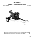
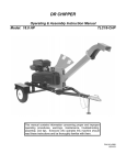
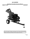
DR CHIPPER
Operating & Assembly Instruction Manual
Model: 18.0 HP
C182-CHP
This manual contains information concerning proper and improper
operating procedures, warnings, maintenance, troubleshooting,
assembly, and tips. Everyone who operates this machine should
read these instructions and be thoroughly familiar with them.
P/N 913-0057
09/18/01
2
SECTION I - SAFETY
This symbol points out important safety instructions which, if not followed,
could endanger the personal safety and/or property of yourself and others. Read and
follow all instructions in this manual before attempting to operate your chipper. Failure
to comply with these instructions may result in personal injury. When you see this
symbol - heed its warning.
THIS MACHINE IS CAPABLE OF INFLICTING SERIOUS INJURY IF
OPERATED IMPROPERLY -- READ WARNINGS & CAUTION LABELS.
INTENDED USE
Never use your chipper for any other purpose than chipping limbs It is designed for this use and any other
use many cause serious injury.
DANGER:
Rotating cutting blade.
Keep hands and feet out of inlet and discharge opening while machine is running.
DANGER:
This machine can CRUSH, GRIND, CUT, and SEVER parts of your body if
they enter the inlet or discharge area of your chipper.
DANGER: Your chipper was built to be operated according to the rules for safe operation
in this manual. As with any type of power equipment, carelessness or error on the part
of the operator can result in serious injury. If you violate any of these rules, you may
cause serious injury to yourself or others.
3
WARNING: The Engine Exhaust from this product contains chemicals known to the state of
California to cause cancer, birth defects or other reproductive harm.
GENERAL OPERATION
•
•
•
•
•
•
•
•
•
•
chipper chute, use a small diameter stick, NOT
YOUR HANDS.
• Keep your face and body back from chipper
chute to avoid accidental bounce back of any
material.
• Do not attempt to chip material larger than
specified in the manual. Personal injury or
damage to the machine could result.
• If it is necessary for any reason to unclog the
feed intake or discharge openings or to inspect or
repair the machine where a moving part can
come in contact with your body or clothing, stop
the machine and allow it to cool. Disconnect the
spark plug before attempting to unclog, inspect or
repair.
• When feeding material into this equipment, be
extremely careful that pieces of metal, rocks, or
other foreign objects are not included. Personal
injury or damage to the machine could result.
• Do not allow an accumulation of processed
material to build-up in the discharge area as this
will prevent proper discharge and can result in
kick-back from the chipper chute.
• If the cutting mechanism strikes a foreign object
or if your machine should start making an
unusual noise or vibration, immediately stop the
engine and allow the machine to come to a
complete stop. Disconnect the spark plug wire
and move it away from the spark plug.
Take the following steps:
a. Inspect for damage.
b. Repair or replace any damaged parts.
c. Check for any loose parts and tighten to assure
continued safe operation.
• Muffler and engine become hot and can cause a
severe burn. Do not touch.
• Do not allow any part of the engine, especially
around the cooling fans and muffler, to become
clogged with leaves, oil, grease or any other
combustible material.
• Do not operate engine if air cleaner or cover over
carburetor air-intake is removed, except for
adjustment. Removal of such parts could create
a fire hazard.
• Keep all other guards and safety devices in place
and operating properly.
• Do not use the unit with the chipper hopper
removed.
• Only use accessories approved for this machine
by the manufacturer. Read, understand, and
follow all the instructions provided with the
approved accessory.
Read this owner’s manual carefully in its entirety
before attempting to assemble this machine.
Read, understand, and follow all instructions on
the machine before operation. Be completely
familiar with the controls and the proper use of
the machine before operating it. Keep this
manual in a safe place for future and regular
reference and for ordering replacement parts.
Your chipper is a powerful tool, not a plaything.
Therefore, exercise extreme caution at all times.
Your unit has been designed to chip. Do not use
it for any other purpose.
Never allow children under the age 16 to operate
the unit. Children 16 years or older should only
operate the unit under close parental supervision.
Only responsible individuals who are familiar with
these rules of safe operation should be allowed
to use your unit.
Always wear safety glasses or safety goggles,
during operation and while performing an
adjustment or repair, to protect eyes from foreign
objects that may be thrown from the machine.
Be sure your glasses fit properly.
Wear sturdy, rough-soled work shoes and close
fitting slacks and shirt. Shirt and slacks that
cover the arms and legs and steel-toed shoes
are recommended. Secure hair above shoulders
and do not wear loose clothes or jewelry that can
be caught in moving parts. Never operate a unit
in bare feet, sandals or sneakers. Wear gloves
when feeding material into the chipper chute. Be
sure your gloves fit properly and do not have
loose cuffs or drawstrings.
Do not operate while under the use of alcohol,
drugs, or medication. A clear mind is essential
for safety.
Do not allow anyone who is not alert to operate
this machine.
The machine should only be operated on a level
surface. Never operate your unit on a slippery,
wet, muddy, or icy surface.
Keep the area of operation clear of all persons,
particularly small children and pets. Stop the
engine when they are in the vicinity of the unit.
Keep work area clean and clear of branches or
obstacles which could cause you to stumble or
fall.
Never place your hands, feet, or any part of your
body in the chipper chute, discharge or near any
moving part while the engine is running. Keep
clear of the discharge opening at all times. If it
becomes necessary to push material into the
4
•
•
Only operate unit in good daylight. Do not
operate unit at night or in dark areas where your
vision may be impaired.
If situations occur which are not covered by this
manual, use care and good judgment. Contact
your dealer for assistance.
CHILDREN
•
Tragic accidents can occur if the operator is not alert to the presence of small children.
• Keep children out of the work area and under the watchful eye of a
responsible adult other than the operator.
• Be alert and turn the unit off if a child enters the area.
• Never allow children under the age of 16 to operate the chipper.
REPAIR AND MAINTENANCE SAFETY
•
•
•
•
•
•
•
•
•
Use extreme care in handling gasoline and other
fuels. They are extremely flammable and the
vapors are explosive.
Store fuel and oil in approved containers, away
from heat and open flame, and out of the reach
of children. Check and add fuel before starting
the engine. Never remove gas cap or add fuel
while the engine is running. Allow engine to cool
at least two minutes before refueling.
Replace gasoline cap securely and wipe off any
spilled gasoline before starting the engine as it
may cause a fire or explosion. Extinguish all
cigarettes, cigars, pipes and other sources of
ignition.
Never refuel unit indoors because flammable
vapors will accumulate in the area.
Never store the machine or fuel container inside
where there is an open flame or spark, such as a
gas hot water heater, space heater, clothes dryer
or furnace.
To reduce fire hazard, keep engine and muffler
free of debris build-up. Clean up fuel and oil
spillage. Allow unit to cool at least five minutes
before storing.
Before cleaning, repairing, or inspecting, make
certain the flywheel and all moving parts have
stopped. Disconnect both spark plug wires and
keep them away from the spark plugs to prevent
accidental starting. Do not use flammable
solutions to clean air filter.
Check the blade and engine mounting screws at
frequent intervals for proper tightness. Also
visually inspect blade for wear or damage.
Replace the blades with parts which meet
original equipment specifications.
•
•
•
•
•
•
Knives should be checked for sharpness and the
nuts and bolts attaching them to the flywheel for
tightness every 8-10 hours of operation.
Never tamper with safety devices. Check their
proper operation regularly.
Never run this machine in an enclosed area as
the exhaust from the engine contains carbon
monoxide, which is an odorless, tasteless, and
deadly poisonous gas.
Never operate your chipper in poor mechanical
condition or when in need of repair. Periodically
check and keep all nuts, bolts, and screws tight
to be sure the equipment is in safe working
condition. Be sure all safety guards and shields
are in proper position. These safety devices are
for your protection.
Inspect the belt each time you use the unit. Look
for damage, worn areas or tears. Do not use the
unit if this condition exists.
If your machine strikes any foreign object or
starts making an unusual noise or vibration,
immediately shut off engine, disconnect spark
plug wire from spark plug, and allow all moving
parts to come to a complete stop. Inspect for
damage and repair and or replace damaged
parts. Check for and tighten any loose parts.
Do not tamper with the engine’s governor setting.
The governor controls the maximum safe
operation speed and protects the engine. Overspeeding the engine is dangerous and will cause
damage to the engine and to the other moving
parts of the machine. See your authorized dealer
for engine governor adjustments.
BEFORE STARTING ENGINE, ALWAYS CHECK OIL LEVEL!
5
•
•
•
•
Only operate your chipper from the operator zone.
Know how to turn your unit off.
Never move your chipper or leave it unattended with the engine running.
Follow engine owner’s manual for engine maintenance and repair.
YOUR RESPONSIBILITY
•
Restrict the use of this power machine to persons who read, understand and
follow the warnings and instructions in this manual and on the machine.
SAVE THESE INSTRUCTIONS
FOR FUTURE REFERENCE.
HAZARD: This unit is equipped with an internal combustion
engine and should not be used on or near any unimproved
forest-covered, brush-covered or grass-covered land unless the
engine’s exhaust system is equipped with a spark arrester
meeting applicable local or state laws (if any).
If a spark
arrester is used, it should be maintained in effective working
order by the operator.
In the State of California, the above is required by law (Section 4442 of the California Public
Resources Code). Other states may have similar laws. Federal laws apply on federal
lands. A spark arrester for the muffler is available through your Briggs & Stratton servicing
dealer.
6
TOWING SAFETY
•
•
•
•
•
Obey all state and local regulations when towing
on public roads and highways.
Before towing, be certain the chipper is correctly
and securely attached to the towing vehicle and
the safety chains are in place. Leave slack in
chains for turning allowance.
Don’t allow anyone to sit or ride on your chipper.
They can easily fall off and be seriously injured.
Never carry any cargo or wood on your chipper.
It may fall off and endanger vehicles following
you.
•
•
Allow for added length for your chipper when
turning, parking, crossing intersections, and in all
driving situations.
Be careful when backing up: you can easily jackknife your chipper.
Adjust towing speed for terrain and conditions.
Do not exceed 35 mph when towing. The
chipper should be level when towing, and it will
pull nicely on smooth roads. Because there is no
suspension, it will tend to bounce more on rough
roads. Be extra cautious when towing over
bumpy or rough terrain including railroad
crossings.
SECTION II - ASSEMBLY INSTRUCTIONS
PACKAGE CONTENTS
SKID
PARTS BOX
BOLT BAG
CHIPPER
HITCH ARMS
HITCH ASSEMBLY
PARTS BOX
CHIPPER HOPPER
STAND
GLASSES
OWNER’S MANUAL
ENGINE MANUAL
BOLT BAG
WIRE HARNESS
10 EA – CABLE TIES
4 EA – 5/16-18 X ¾” CARRIAGE BOLTS
4 EA – 5/16-18 NYLOCK NUT
4 EA – 5/16 USS FLATWASHER
2 EA – ½-13 X 3” HHCS
4 EA – ½-13 X 1 ¼” HHCS
2 EA – ½-13 GRIPCO NUT
1 EA – 3/16 HAIR COTTER PIN
2 EA – HITCH ARM MOUNTING PLATES
1 EA – ENGINE KEY
TOOLS REQUIRED FOR ASSEMBLY
• 7/16” Wrench or Socket - 2 required
• 1/2” Wrench or Socket - 2 required
• 3/4” Wrench or Socket - 2 required
STEP I – UNPACKING AND CHECKING CONTENTS
1. Remove the all items from the crate.
2. After unpacking the crate, compare the contents with the list above.
3. If any parts are missing, contact Country Home Products at 800-376-9637.
4. Assembly should be done on a clean, level surface.
STEP II – ASSEMBLY
1. Assemble chipper hopper (item #15, pg. 19) to machine using four each 5/16”-18 x 3/4” carriage bolts, 5/16”-18
nylock nuts and 5/16” flatwashers. Put head of bolt inside hopper with threads sticking out. Tighten all
hardware with a ½” wrench.
2. Attach the hitch arms (item #5, pg. 17) to the trailer frame using the two hitch arm mounting plates (item #22,
pg. 17) and four 1/2”-13 x 1-1/4” HHCS from the bolt bag. Do not tighten hardware at this time.
3. Attach the trailer hitch assembly (item #6 & #9, pg. 17) to the hitch arms as shown in drawing with two 1/2”-13 x
3” HHCS and two 1/2”-13 gripco nuts from the bolt bag. Tighten all hardware at this.
4. Slide the stand (item #7, pg 17) up through the holes in the hitch assembly and secure with the hair cotter pin
(item #36, pg. 17).
5. Service the engine as per the engine manual.
6. Lubricate both bearings before operating and after every 8 hours of operation with multi-purpose grease. Also
check the bearing collar set screws regularly to be sure they are tight. If they are loose, reset them with loctite
243, obtainable at any hardware store.
7
STEP III – ATTACHING WIRE HARNESS
Identify the “road side” and “curb side” of your trailer per the picture below. The mounting brackets have an access
hole in them so the wire harness can be attached to the light. On the wire harness the yellow/brown wire is for the
road side light and the green/brown wire is for the curb side light. The white wire is a ground wire.
To attach the wire harness to the lights and frame proceed as follows.
1. Strip ½” off the ends of the yellow/brown and green/brown wires.
2. On the road side light put the yellow wire through the access hole and into the top left hole on the back of
the light. Push the brown wire into the top right hole.
3. On the curb side light put the green wire through the access hole and into the top left hole on the back of
the light. Push the brown wire into the top right hole.
4. Once the wires are attached in their correct holes attach the wire harness to the frame with the provided
cable ties.
5. Attach the curb side wire to the frame at points 1, 2 and 3 per the drawing.
6. Attach the road side wire to the frame at point 4.
7. Attach both wires together at points 5, 6, 7 and 8.
8. Strip 1” from the end of the ground wire and wrap it around one of the bolts on the trailer hitch. Retighten
this bolt.
NOTE: Once the wires are being secured together (point 5), it is recommended that they be wrapped together
with electrical tape every twelve inches.
8
SECTION III - OPERATION
BEFORE STARTING:
Gas and Oil Fill-Up
BEFORE STARTING ENGINE, ALWAYS CHECK OIL LEVEL!
Refer to the engine owner’s manual for further details regarding the engine.
NOTE: ENGINE IS SHIPPED WITHOUT OIL !! FILL CRANKCASE WITH OIL BEFORE STARTING ENGINE.
Be very careful not to allow dirt to enter the engine when checking or adding oil or fuel.
TO FILL OIL
•
•
•
•
•
To initially fill oil, the chipper must be in the upright position and the engine level.
Clean around the oil dipstick.
Remove the oil dipstick, fill the engine with oil.
Add oil slowly and wait several minutes for oil to settle before rechecking oil level.
Replace and tighten the oil dipstick.
TO FILL GAS
•
•
•
Fill the fuel tank with fresh, clean unleaded regular automotive gasoline. (Leaded regular and
unleaded or leaded premium grades of gasoline are acceptable substitutes.)
Do not mix oil with gasoline.
Do not use gasoline left over from last season or that has been stored for more than 30 days.
TO ADD OIL
•
•
•
•
•
•
The Chipper must be in the upright position and the engine level.
Clean around the oil dipstick.
Remove the oil dipstick, wipe it clean and check oil level.
Fill to the oil full mark on the dipstick.
If required, add oil slowly and wait several minutes for oil to settle before rechecking oil level.
Replace and tighten the oil dipstick.
TO ADD GASOLINE
•
•
•
•
Shut off the engine and disconnect the spark plug wire from the spark plug. Allow the engine and muffler to
cool for at least three minutes.
Clean the area around the fuel cap and remove the cap from the fuel tank. Insert a clean funnel into the fuel
tank.
Fill the fuel tank to 1 inch below the bottom of the filler neck to provide space for any fuel expansion.
Reinstall the fuel fill cap securely and wipe up any spilled gasoline.
9
WARNING: Do not fill closer than one inch to the top of fuel tank to prevent spills and to allow
for fuel expansion. If gasoline is accidentally spilled, move unit away from area of spill. Avoid
creating any source of ignition until gasoline vapors have disappeared.
CAUTION: Experience indicates that alcohol blended fuels (called gasohol or using ethanol or methanol) can
attract moisture which leads to separation and formation of acids during storage. Acidic gas can damage the fuel
system of an engine while in storage. To avoid engine problems, use fresh fuel every 30 days. Never use engine
or carburetor cleaner products in the fuel tank or permanent damage may result.
NOTE: USE CLEAN OIL AND FUEL. STORE IN APPROVED,
CLEAN, COVERED CONTAINERS. USE CLEAN FILL FUNNELS.
ENGINE STARTING INSTRUCTIONS
A.
B.
C.
D.
E.
F.
There is a fuel shut-off valve below the gas tank on your machine. Before starting the chipper, be sure the
fuel shut-off valve is open (the tab should be vertical). When transporting and storing the chipper, close
the fuel shut-off valve to prevent leakage (tab should be horizontal).
Locate choke lever (ring under air clearner approximately 8” left of starter button).
Move choke lever to “FULL CHOKE POSITION” by pulling ring straight out.
NOTE: IF RESTARTING A WARM ENGINE AFTER A SHORT SHUTDOWN, MOVE CHOKE
LEVER TO “NO CHOKE POSITION”.
Move toggle switch lever away from “STOP” position.
Push starter button to crank engine.
Crank engine until it fires. When it starts, release starter button and move choke ring to “1/2 CHOKE”
until engine runs smoothly and then to “NO CHOKE POSITION”.
If engine falters, move choke lever to “1/2 CHOKE” until engine runs smoothly and then to “NO CHOKE
POSITION” by pushing choke ring in.
NOTE: If engine fires, but does not continue to run, move choke lever to “NO CHOKE POSITION” and
crank engine until it starts.
NOTE: If engine again fires, but does not continue to run, move choke lever to “FULL CHOKE” and
repeat instructions C, D, and E until engine starts.
ENGINE STOPPING INSTRUCTIONS
•
Move toggle switch to “STOP” position.
Engine running speed is preset by engine manufacturer - it only runs at full speed.
DO NOT tamper with engine settings this could damage engine and will void engine warranty.
Whenever you operate your chipper, wearing gloves
and safety glasses is required. If necessary to push
material into chipping chamber, use a wood stick,
never your hands or steel implements. At the end of
this section, we offer additional cautions. Read and
observe them.
Branches are fed into the side hopper for chipping. If
they are thicker than 2” in diameter, feed only one
branch at a time. For smaller diameter sticks and
twigs, several may go together. Since the throat
opening is approx. 4-1/2” square, some side shoots
or side branches may have to be trimmed from the
main stalk before the chipping process. Short stubs
of branches may be pushed through the chipper
section with the next branch. Never assume you
know where the blade is, and try to push short
branches in by hand. You don’t know where it is. Be
safe, keep your hands away from the chipping blade.
As the engine ignition begins, the engine operates
under no load until approximately 1200-1400 rpm at
which speed the centrifugal clutch engages and
begins driving the rotor. Proper rotor speed is in the
2400 rpm range with a plus or minus tolerance of 200
rpm.
When viewed from the pulley side of the chipper
body, the flywheel runs counterclockwise. This
action tends to pull materials into the chipping
chamber.
10
SECTION IV - CHIPPING
1. To process branches, dry or green feed into the chipper hopper. It is best to clip off side twigs or limbs from
the main branch. Enter one branch at a time if they are 2” or more in diameter. Green branches process
quicker and easier then dry branches and soft wood is easier than hardwood. Push the branch in at the angle
of the hopper and throat. Always have the removable hopper in place. Never allow your hands to enter the
hopper. As the chip branch shortens, finish chipping it by shoving the stub down the chipper tube with the next
branch to be chipped.
2. When chipping branches, sometimes a tail will be left at the end of the branch (usually green wood), which will
increase in length as you chip and eventually rap around the shaft or bearings. To avoid this we recommend
twisting the branch as you feed it into the chute. This will also improve the chipping performance.
Use common sense when using your chipper. Learn to recognize the change in sound when it is overloaded. If
the machine becomes jammed by overloading or another cause, stop the engine immediately and no damage will
occur. IF YOU JAM THE UNIT AND DO NOT STOP THE ENGINE, IT WILL BURN THE BELT OR RUIN THE
CLUTCH. To free a jammed flywheel, stop the engine, remove both spark plug wires and remove the material left
in the chipping chamber. It may be necessary to remove the deflector cover (item #1, pg. 17) to allow easier
cleaning of the machine. Make sure to replace deflector cover with all supplied hardware to reduce risk of injury.
Check to see that the flywheel will turn freely before you start the chipper. Only your operator experience will tell
you how fast to feed limbs.
WARNING: Do not allow chips to build up within 3” of
discharge chute opening. Move chipper or pile as needed.
Failure to do this could result in unnecessary jamming of
machine.
To move pile, use spade, rake, or long handle tool.....
NEVER USE YOUR HANDS OR FEET!!!
1. Never allow your hands or any part of your body or clothing inside the feed hopper or discharge area of the
chipper. Use a wood stick to push material down the hopper.
2. Keep all protective guards on the machine and deflectors in place and in good working condition.
3. Always stand clear of the discharge area when the chipper is running.
4. Keep your face and body back from the feed hopper to avoid being struck by any material that may bounce
back. Do not overreach, keep proper balance and footing.
5. Do not transport the chipper while the engine is running.
6. Do not refuel the engine while it is hot, warm, or running.
7. Do not cover the chipper while the muffler is still hot.
SECTION V - MAINTENANCE AND STORAGE
IMPORTANT: Knives should be checked for sharpness and the nuts and bolts attaching them to the
flywheel for tightness every 8-10 hours of operation.
If the cutting mechanism strikes any foreign object or if your machine should start making an
unusual noise or is vibrating, stop the engine, disconnect both spark plug wires from the spark
plug. Allow the engine to cool before you;
a. Inspect and examine for obvious damage.
b. Check for loose parts, bolts, and nuts.
1. When not in use, your chipper should be stored out of the reach of children. Be sure there are no gasoline
fumes in the storage area. For long periods of storage (over winter), refer to the engine owner’s manual.
2. After every 10 hours of operation, lubricate the chipper side and drive side bearings with multi-purpose lithium
grease. Also, check the bearing collar set screws regularly to be sure they are tight. If they are loose, reset
them with loctite 243 or equivalent, obtainable at any hardware store.
3. You will find information included referring to operation and maintenance of the chipper engine. Look it over
carefully. BE CERTAIN TO SERVICE THE ENGINE BEFORE YOU START IT.
4. When the steel chipping knives (item #8, pg. 19) need replacing or sharpening, refer to the section on removal
and re-installation of chipper knives on pg. 12.
5. Care must be exercised when sharpening the blade to maintain the correct bevel and a straight edge. When
you install a knife, the clearance between knives and wear plate
must be checked. This clearance or gap should be minimum
1/16”, maximum 3/16” (See figure 3). To adjust this clearance,
loosen the three 1/4 inch flathead bolts (item #11, pg. 19) which
are located on the outside of the chipper wear plate (item #12, pg.
19) next to the chipper side plate. Move the wear plate in or out as
necessary and tighten the ¼ inch nuts securely.
6. Note, if the gap between chute plate and knife is excessive, you
will have vibration when chipping and the blade will seem to be
dull.
7. If at any time it becomes necessary to disassemble the chipper for
repairs, the chipping disc (item #3, pg. 19) must be re-installed in
exactly the same position on the shaft.
Figure 3
BEFORE STARTING ENGINE, ALWAYS CHECK OIL LEVEL!
12
REMOVAL AND RE-INSTALLATION OF CHIPPER KNIVES
HOW TO REMOVE THE KNIFE
1.
2.
3.
4.
Remove the spark plug wires from both spark plugs.
Remove both access covers from the chipper basic machine.
Rotate the chipper disc until the three countersunk screws and nylock nuts holding the blade are visible
through the access doors.
To remove these screws do the following.
A.
B.
C.
D.
Clean out the heads of the allen screws (item #9, pg. 19) with an awl or sharp tool.
Insert a 3/16 allen wrench into the heads of the screws.
Use a ½” socket and ratchet to remove the nylock nut from the screws.
Remove all three screws in this manner.
HOW TO SHARPEN AND REINSTALL THE KNIFE
KNIFE SHARPENING
A properly sharpened knife looks like this:
Chipper Knives - These hardened knives must be routinely
checked for sharpness. Using dull knives decreases performance
and causes excessive vibration and damage to the unit. DO NOT
ATTEMPT TO SHARPEN KNIVES FREE HAND. Knives must be
parallel ground and kept in a matched set. Take the knives to a
sharpening service to be sharpened. After sharpening the knives,
be sure to re-gap the knives and wear plate. This gap should be a
minimum of 1/16” to a maximum of 3/16”.
RIGHT (45º)
WRONG
KNIFE INSTALLATION
1. When installing new knives, be sure disc is clean before
positioning knife.
2. Reinstall the screws and nylock nuts that were removed while taking the knives off.
3. Check and reset the gap between the knives and the wear plate. New knives will require the wear plate to be
backed out for additional clearance before the new knives can pass.
WEAR PLATE
The wear plate should be kept with a square edge and free of nicks
Test the unit by turning the flywheel by hand to check for proper clearance. Watch and listen carefully for any
unusual noises, clicking or vibration. If any of these are detected, inspect the machine for damage, repair or
replace any damaged parts and check for any loose parts and retighten.
13
INSTRUCTIONS FOR ADJUSTING OR REPLACING BELT
If the belt needs replacing or tightening, follow these instructions carefully.
1. Remove the belt guard (item #27, pg.17).
2. Check alignment of the clutch (item #20, pg. 17) with drive pulley (item #18, pg. 17) by placing a straight-edge
across both faces (see figure 1). If adjustment is necessary, adjust rotor pulley. DO NOT ADJUST BY
MOVING CLUTCH ON ENGINE SHAFT.
3. Loosen engine bolts and nuts (items #50 & #51, pg. 17).
4. Install the drive belt (item #21, pg. 17) and tighten belt tensioner (item #30, pg. 17) until belt deflection is as
shown in figure 2.
5. Tighten engine mounting bolts and nuts securely.
6. Re-install the belt guard before operating your unit.
Figure 1
Figure 2
NOTE: Check and re-tighten belt after
break-in period.
TROUBLESHOOTING
Symptom
Problem
Correction
Clutch overheats.
Clutch is slipping or flywheel is
jammed or stopped.
A. Immediately stop engine.
B. Remove spark plug wire.
C. Turn flywheel by hand to be sure it
turns freely.
D. Check belt tension.
Run engine at full throttle.
Check for loose or missing belt &
tighten.
Remove knife & sharpen - be sure to
maintain same bevel of 45 degrees.
Adjust gap as per instructions.
If key in taper lock bearing is too deep,
file key to seat properly. Reset the
proper knife gap & tighten set screws.
Replace worn or broken clutch parts.
Check belt tension.
Clear chipper chamber.
Belt burns.
Flywheel won’t turn.
Chipping action seems too slow or
flywheel stalling.
When chipping, log seems to
vibrate excessively & “hammers”
hands.
Chipper knives move over and are
striking chipper side plate.
Engine runs but flywheel doesn’t
rotate.
Engine speed is too slow.
Belts are slipping.
Knives are dull.
Gap between knife & wear plate is
too great.
Taper lock bushing is loose.
Set screws in flywheel shaft bearings
are loose or missing.
Inner shoes of clutch worn.
Retaining springs weak or broken.
Loose drive belt.
14
LUBRICATION AND MAINTENANCE
OPERATION
TIME
PROCEDURE
COMMENTS
BREAK-IN
Change engine oil and filter after first 5
hours.
Check belt tension.
Check all nuts and bolts for tightness.
Per manufacturer’s specifications.
8 HOURS
Check engine oil.
Check chipper knives gap and edge.
Clean air filter.
Remove hubs from axle and grease.
Grease flywheel shaft bearings. (1)
Do not over fill.
See knife maintenance section.
More often if needed.
Anti seize compound.
Good grade multi-purpose lithium
grease.
40 HOURS
Change engine oil. (2)
Check tire pressure.
Remove and sharpen or replace
chipper knives.
Per manufacturer’s specifications.
Add or adjust as required.
See knife maintenance section.
100 HOURS
Replace belt.
Change engine oil.
Order replacement part.
Per manufacturer’s specifications.
200 HOURS
Clean and adjust spark plug.
Per manufacturer’s specifications.
Adjust as required.
Tighten if necessary.
(1) Two pumps of hand gun. DO NOT over-grease as this may damage seal.
(2) Depending on climate and environment, lubrication may be required every 8 to 40 hours.
ACCESSORIES FOR C182-CHP
Water resistant fitted cover
Order Part No. 913-0069
15
CENTRIFUGAL CLUTCH INSTALLATION AND SERVICING INSTRUCTIONS
FOR CLUTCH PART NUMBER 911-0236
REMOVAL
1. Remove clutch from shaft by removing bolt and washers.
2. Slide clutch off shaft.
3. Remove key from keyway.
INSTALLATION
1.
2.
3.
4.
5.
6.
Clean the shaft and remove any burrs.
Install spacer onto shaft.
Apply anti-seize compound to shaft.
Place key in keyway in shaft.
Slide clutch onto shaft.
Secure clutch with washer and bolt. Be sure to use loctite 243 on the threads of the bolt.
MAINTENANCE
The centrifugal clutch on this machine is permanently lubricated and does not require oil or grease. Always replace
shoes and springs in sets; whenever shoes are changed, replace all springs.
DISASSEMBLY OF EXISTING CLUTCH
1. Remove retainer ring and press off drum assembly.
2. Release one hook end of spring from shoe pin. Use tape wrapped pliers to avoid nicking spring.
3. Remove shoes from hub.
RE-ASSEMBLY
1. Locate the shoes correctly on the hub for rotation required.
2. Place one end of each spring in hole at end of shoe, stretch spring just enough to clear hole on adjacent shoe.
Use tape wrapped pliers to avoid nicking spring. Avoid overstretching spring as this may damage spring.
Repeat for all shoes.
3. Re-assemble drum to hub, secure with retaining ring.
4. Re-install clutch on shaft.
CLUTCH PARTS LIST
Complete Part 911-0236
Item No.
Part No.
Quantity
1
2
3
4
6
911-0236-3
911-0046-4
911-0236-5
911-0046-2
912-2644-7
1
3
3
1
2
Description
Hub Assy.
Shoe
Spring
Drum Assy.
Retaining Ring
16
PARTS LIST C182-CHP CHIPPER
ITEM #
1
2
3
4
5
6
7
8
9
10
11
12
13
14
15
16
17
18
19
20
21
22
23
24
25
26
27
28
29
30
31
33
34
35
36
37
38
39
40
41
42
43
44
45
46
47
49
50
51
52
53
55
56
57
58
---------
QTY.
1
1
1
1
2
1
1
2
1
1
2
4
2
2
1
1
1
1
1
1
2
2
1
1
1
1
1
1
1
1
1
1
1
2
1
4
1
1
4
4
4
2
18
3
11
3
15
4
17
3
1
1
4
4
2
1
1
1
1
PART #
913-0023
913-0215
030-0231
913-0049
911-0219
911-0220
911-0035
408-0078
913-0218
911-0070
911-0210
911-0229
911-0025
702-0040
913-0124
913-0086
913-0217
030-0211
030-0237
911-0236
030-0193
911-0221
913-0056
913-0058
911-0214
911-0240
911-0248
030-0232
913-0053
913-0054
030-0239
913-0203
030-0266
913-0206
500-0039
090-0162
911-0249
704-0106
090-0128
090-0370
090-0050
703-0424
090-0088
090-0394
090-0233
090-0438
090-0461
090-0066
090-0460
090-0234
090-0123
090-0422
090-0111
090-0453
090-0077
030-0265
913-0059
911-0228
030-0267
17
DESCRIPTION
DEFLECTOR
CHIPPER BASIC MACHINE
18HP BRIGGS & STRATTON ENGINE
FRAME WELDMENT
HITCH ARMS
HITCH TUBE WELDMENT
STAND
SAFETY CHAIN
TRAILER HITCH
AXLE WELDMENT
AXLE BRACKET WELDMENT
3/8-16 X 3” U-BOLT
FENDER WELDMENT
TIRES
BATTERY BOX
BATTERY
BATTERY HOLD DOWN
PULLEY
BUSHING
CLUTCH
5H680 BELT
HITCH ARM MOUNTING PLATES
BELT GUARD “L” MOUNTING BRACKET
BELT GUARD “Z” MOUNTING BRACKET
BELT GUARD “L” MOUNTING BRACKET
INNER BELT GUARD
BELT GUARD WELDMENT
GAS TANK
GAS TANK MOUNTING BRACKET
ENGINE/BELT TIGHTENER
HOSE AND CLAMP ASSEMBLY
BATTERY SPACER
ROAD SIDE STOP LIGHT
TAIL LIGHT MOUNTING BRACKET
3/16” HAIR SPRING COTTER
10-32 X 3/8” SELF TAPPING SCREW
SPACER
WASHER
½-13 X 1 ¼” HHCS
½-13 X 3” HHCS
½-13 GRIPCO LOCKNUT
¼ X ¼ X 2” KEY
5/16-18 X 1” HHCS
5/16 SPLIT LOCKWASHER
5/16 USS FLATWASHER
5/16-18 J-NUT
3/8-16 NYLOCK NUT
5/16-18 X 1 ¾” HHCS
5/16-18 NYLOCK NUT
3/8 USS FLATWASHER
3/8-16 X 3 ½” HHCS
3/8-24 X 1 ½” HHCS
3/8-16 X 1 ¼” HHCS
¼-20 WHIZ NUT
5/16-18 X 4” HHCS
CURB SIDE STOP LIGHT
POSITIVE BATTERY CABLE
NEGATIVE BATTERY CABLE
WIRE HARNESS
PARTS BREAKDOWN C182-CHP CHIPPER
18
PARTS LIST – 913-0215 CHIPPER BASIC MACHINE
Item No.
Qty.
Part No.
Description
1
2
3
4
5
6
7
8
9
10
11
12
13
14
15
16
17
18
19
20
21
22
23
24
25
26
27
1
9
1
1
1
1
1
2
6
2
3
1
10
8
1
4
9
3
4
3
4
2
8
1
2
2
2
913-0034
090-0048
911-0163
030-0118
500-0031
913-0022
913-0042
911-0010
090-0642
913-0021
090-0257
911-0055
090-0460
090-0233
911-0164
090-0462
090-0077
090-0245
090-0111
090-0470
090-0042
030-0115
090-0162
913-0035
090-0024
030-0117
913-0210
DRIVE SIDE PLATE WELDMENT
5/16-18 GRIPCO NUT
CHIPPER DISC WELDMENT
FLYWHEEL TAPERLOCK
¼ X ¼ X 1” KEY
FLYWHEEL SHAFT
SCROLL WELDMENT
KNIFE
5/16-18 X 1 ½” SOCKET HEAD CAP SCREW
SCROLL TUBE
¼-20 X 1” SOCKET FLAT HEAD SCREW
WEAR PLATE
5/16-18 NYLOCK NUT
5/16 USS FLATWASHER
CHIPPER HOPPER
5/16-18 X ¾’ CARRIAGE BOLT
5/16-18 X 4” HHCS
¼ SAE FLATWASHER
3/8-16 X 1 ¼” HHCS
¼-20 NYLOCK NUT
3/8-16 GRIPCO NUT
SHAFT BEARING
10-32 X 3/8 SELF TAPPING SCREW
CHIPPER SIDE PLATE WELDMENT
SHIM
RETAINING RING
ACCESS COVER
CHECK OIL LEVEL
BEFORE STARTING CHIPPER
19
PARTS BREAKDOWN – 913-0215 CHIPPER BASIC MACHINE
20
ROTATING CUTTING BLADES - KEEP HANDS AND FEET OUT OF
DISCHARGE AND INLET OPENING WHILE MACHINE IS RUNNING.
Part No. 091-0055
1.
2.
Part No. 080-0967
3.
4.
5.
6.
7.
ROTATING CUTTING BLADES - KEEP HANDS OUT OF INLET
OPENING WHILE MACHINE IS RUNNING.
READ INSTRUCTIONS THOROUGHLY BEFORE OPERATING
THE MACHINE.
NEVER OPERATE THE CHIPPER WITHOUT THE FEED
CHUTE SECURELY IN PLACE.
USE GLOVES AND APPROVED SAFETY GLASSES WHEN
OPERATING.
DO NOT INSERT HANDS OR METAL OBJECTS INTO THE
FEED HOPPER OR DISCHARGE CHUTE WHEN THE
MACHINE IS RUNNING. IF JAMMED TURN ENGINE OFF AND
REMOVE SPARK PLUG WIRE BEFORE CLEARING THE
OBSTRUCTION.
DO NOT ALLOW BYSTANDERS, ESPECIALLY CHILDREN,
NEAR THE MACHINE.
KEEP HANDS, FACE AND LOOSE CLOTHING AWAY FROM
MOVING PARTS.
CAUTION SHUT DOWN ENGINE
REMOVE SPARK PLUG WIRE
BEFORE OPENING.
Part No. 080-0970
Part No. 091-0057
21
COUNTRY HOME PRODUCTS
Meigs Road, P.O. Box 25, Vergennes, Vermont 05491
1(800) DR-OWNER (376-9637)
2000 CHP Inc. 157611
09/18/01
22