1
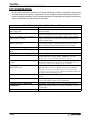
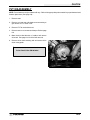
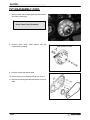
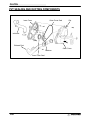
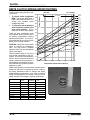
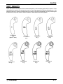
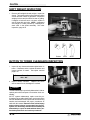
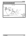
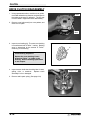
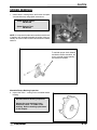
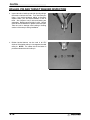
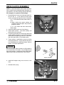
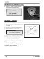
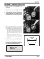
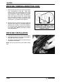
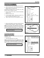
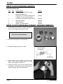
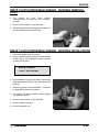
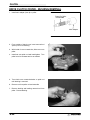
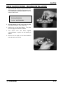
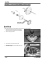
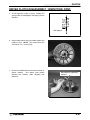
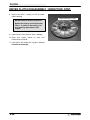
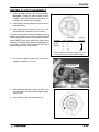
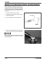
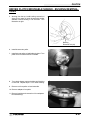
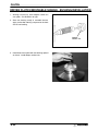
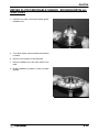
CHAPTER 6 PVT SYSTEM Service Tools and Supplies . . . . . . . . . . . . . . . . . . . . PVT System Operation . . . . . . . . . . . . . . . . . . . . . . . . PVT Maintenance/Inspection . . . . . . . . . . . . . . . . . . . PVT Disassembly . . . . . . . . . . . . . . . . . . . . . . . . . . . . . PVT Assembly . . . . . . . . . . . . . . . . . . . . . . . . . . . . . . . PVT Sealing and Ducting Components . . . . . . . . . . Clutch System Operation Overview . . . . . . . . . . . . . Drive Clutch Spring Specifications . . . . . . . . . . . . . . Shift Weights . . . . . . . . . . . . . . . . . . . . . . . . . . . . . . . . . Drive Clutch Inspection . . . . . . . . . . . . . . . . . . . . . . . . Drive Clutch Exploded View . . . . . . . . . . . . . . . . . . . . Drive Clutch Disassembly/Inspection . . . . . . . . . . . . Drive Clutch Assembly . . . . . . . . . . . . . . . . . . . . . . . . Drive Belt Tension . . . . . . . . . . . . . . . . . . . . . . . . . . . . Drive Belt Removal/Inspection . . . . . . . . . . . . . . . . . Drive Belt Installation . . . . . . . . . . . . . . . . . . . . . . . . . . Clutch Alignment /Offset . . . . . . . . . . . . . . . . . . . . . . . Drive Clutch Bushing Service . . . . . . . . . . . . . . . . . . Driven Clutch Disassembly/Inspection . . . . . . . . . . . Driven Clutch Assembly . . . . . . . . . . . . . . . . . . . . . . . Driven Clutch Bushing Service . . . . . . . . . . . . . . . . . Troubleshooting . . . . . . . . . . . . . . . . . . . . . . . . . . . . . . 6.1 6.2 6.3-6.4 6.5-6.6 6.7 6.8 6.9 6.10 6.11 6.12 6.13 6.14-6.16 6.17-6.18 6.18 6.19-6.20 6.20 6.21 6.22-6.25 6.26-6.28 6.29 6.30-6.33 6.34-6.35 6 CLUTCH SPECIAL SERVICE TOOLS AND SUPPLIES Description Drive Clutch Puller . . . . . . . . . . . . . . . . . . . . . . . . . Clutch Holding Fixture . . . . . . . . . . . . . . . . . . . . . Spider Removal Tool . . . . . . . . . . . . . . . . . . . . . . . Offset / Alignment Tool (Std) . . . . . . . . . . . . . . . . Driven Clutch Puller . . . . . . . . . . . . . . . . . . . . . . . Spider Pin Tool . . . . . . . . . . . . . . . . . . . . . . . . . . . . Clutch Bushing Removal & Installation . . . . . . . Piston Pin Puller (Used with 2871226) . . . . . . . . Loctitet 680 . . . . . . . . . . . . . . . . . . . . . . . . . . . . . RTV Silicone Sealer . . . . . . . . . . . . . . . . . . . . . . . Loctite Gasket Remover . . . . . . . . . . . . . . . . . . . . Part Number 2870506 2871358 2870341 2870654 2870913 2870910 2871226 2870386 2870584 2870661 2870601 PVT SYSTEM FASTENER TORQUES Drive Clutch Retaining Bolt . . . . . . . . . . . . . . . . . Driven Clutch Retaining Bolt . . . . . . . . . . . . . . . . PVT Inner Cover Bolts . . . . . . . . . . . . . . . . . . . . . Drive Clutch Spider (Standard Clutch) . . . . . . . . Drive Clutch Cover Plate . . . . . . . . . . . . . . . . . . . 40 ft. lbs. 17 ft. lbs. 12 ft. lbs. 200 ft. lbs. 90 in. lbs. 6.1 CLUTCH PVT OPERATION The Polaris variable transmission (PVT) consists of three major assemblies: 1) drive clutch; 2) drive belt; and 3) driven clutch. The internal components of the drive clutch and driven clutch control clutch engagement (for initial vehicle movement), clutch upshifting and backshifting. During the development of an ATV, the PVT system is matched first of all to the engine power curve; then to average riding conditions and to vehicle design usage. Modifications to the PVT or variations of components at random are never recommended. Proper PVT system setup and careful inspection of existing components must be the primary objective when troubleshooting and tuning. WARNING All PVT system maintenance repairs must be performed only by an authorized Polaris service technician who has attended a Polaris sponsored service training seminar and understands the proper procedures as outlined in this manual. Because of the critical nature and precision balance incorporated into the PVT system, it is absolutely essential that no attempt at disassembly or repair be made without factory authorized special tools and service procedures. DRIVE CLUTCH OPERATION The drive clutch primarily senses engine RPM. The two major components which control its shifting function are the shift weights and the coil spring. When the engine RPM is increased, the centrifugal force of the shift weights working against the coil spring increases. When this force reaches a force higher than the preload in the spring, the moveable sheave of the drive clutch will move inward, contacting the drive belt. The force will pinch the belt between the spinning sheaves and cause the drive belt to move. This movement in turn rotates the driven clutch. At light throttle settings the drive belt will stay low in the drive clutch and high in the driven clutch. As engine RPM increases, so does the centrifugal force on the shift weights, causing the drive belt to be forced upward in the drive clutch and downward into the driven clutch. The forces in the driven clutch will now affect the upshift. DRIVEN CLUTCH OPERATION The driven clutch primarily senses torque. It opens and closes according to the forces applied to it from the drive belt and the transmission input shaft. If the torque resistance on the input shaft is greater than the load from the drive belt, it will keep the drive belt outward at the top of the driven clutch sheaves. As the throttle setting and engine horsepower increase, there will be a greater load on the drive belt, pulling the belt down into the driven clutch and up on the drive clutch. This action, which increases the driven clutch speed, is called upshifting. If the throttle setting remains the same and the vehicle is subjected to a heavier load, the driven clutch senses this load, moving the belt back up on the sheaves of the driven clutch and down into the sheaves of the drive clutch. This action, which decreases the driven clutch speed, is called downshifting. In situations where loads vary (such as uphill and downhill) and throttle settings are constant, the drive and driven clutches are continually shifting to maintain optimum engine RPM. At full throttle a perfectly matched PVT system will hold the engine RPMs at the peak of the power curve. This RPM should be maintained during clutch upshift and backshift. In this respect the PVT system is similar to a power governor. Rather than change throttle position, as a governor does, the PVT system changes engine load requirements by either upshifting or downshifting. 6.2 CLUTCH PVT MAINTENANCE/INSPECTION Under normal operation the PVT system will provide years of trouble free operation. Periodic inspection and maintenance is required to keep the system operating at peak performance. The following list of items should be inspected and maintained to ensure maximum performance and service life of PVT components. Refer to the troubleshooting checklist at the end of this chapter for more information. 1. Belt Tension, Drive to Driven Clutch Offset, Belt Width. See pages 6.18-6.19, and 6.21. 2. Drive and Driven Clutch Buttons and Bushings, Drive Clutch Shift Weights and Pins, Drive Clutch Spider Rollers and Roller Pins, Drive and Driven Clutch Springs. See pages 6.10-6.11 and 6.14-6.15. 3. Sheave Faces. Clean and inspect for wear. 4. PVT System Sealing. Refer to appropriate illustration below and on the following pages. The PVT system is air cooled by fins on the drive clutch stationary sheave. The fins create a low pressure area in the crankcase casting, drawing air into the system through an intake duct. The opening for this intake duct is located at a high point on the vehicle (location varies by model). The intake duct draws fresh air through a vented cover. All connecting air ducts (as well as the inner and outer covers) must be properly sealed to ensure clean air is being used for cooling the PVT system and also to prevent water and other contaminants from entering the PVT area. This is especially critical on units subjected to frequent water forging. PVT DRYING If water is ingested, shift transmission to neutral and rev engine slightly to expel the moisture and air-dry the belt and clutches. Allow engine RPM to settle to idle speed, shift transmission to lowest available range and test for belt slippage. Operate ATV in lowest available range for a short period of time until PVT system is dry. 6.3 CLUTCH PVT OVERHEATING During routine maintenance or whenever PVT system overheating is evident, it’s important to check the inlet and outlet ducting for obstructions. Obstructions to air flow through the ducts will significantly increase PVT system operating temperatures. The ATV should be operated in LOW RANGE when pulling or plowing heavy loads, or if extended low speed operation is anticipated. Clutch Drive Belt & Cover Related Issues: Diagnosis Possible Causes Loading the ATV into a pickup or tall trailer when in high range. Starting out going up a steep incline. Solutions/What to do Shift transmission to low range during loading of the ATV to prevent belt burning. When starting out on an incline, use low range, or dismount the ATV after first applying the park brake and perform the “K” turn. Driving at low RPM or low ground speed (at Drive at higher speed or use Low Range. The use of Low Range is approximately 3-- 7 MPH). highly recommended for cooler PVT operating temperatures and longer component life. Insufficient warm-- up of ATVs exposed to low Warm engine at least 5 min., then with transmission in neutral, adambient temperatures. vance throttle to approx. 1/8 throttle in short bursts, 5 to 7 times. The belt will become more flexible and prevent belt burning. Slow and easy clutch engagement. Fast, effective use of the throttle for efficient engagement. Towing/Pushing at low RPM/low ground Use Low Range only. speed. Plowing snow, dirt, etc./utility use. Use Low Range only. Stuck in mud or snow. Shift the transmission to Low Range, carefully use fast, aggressive throttle application to engage clutch. WARNING: Excessive throttle may cause loss of control and vehicle overturn. Climbing over large objects from a stopped Shift the transmission to Low Range, carefully use fast, aggressive, position. brief throttle application to engage clutch. WARNING: Excessive throttle may cause loss of control and vehicle overturn. Belt slippage from water or snow ingestion Shift the transmission to neutral. Using the throttle, vary the engine into the PVT system. rpm from idle to full throttle. Repeat several times as required. During this procedure, the throttle should not be held at the full position for more than 10 seconds. Clutch seals should be inspected for damage if repeated leaking occurs. Clutch malfunction. For inspection of clutch components, please contact your Polaris dealer. Poor engine performance. Fouled plugs, foreign material in gas tank, fuel lines, or carburetor. Contact you dealer for further service information. GENERAL RANGE OPERATION GUIDELINES: 6.4 Low Range: Heavy pulling, basic operational speeds less than 7 MPH, riding through rough terrain (swamps, mountains, etc.), low ground speeds. High Range: High ground speeds, speeds above 7 MPH. CLUTCH PVT DISASSEMBLY NOTE: Some fasteners and procedures will vary. Refer to the appropriate parts manual for proper fasteners and fastener placement. (See page 6.8). 1. Remove seat. 2. Remove or loosen rear cab fasteners as necessary to gain access to PVT outer cover. 3. Remove PVT air outlet duct hose. 4. Remove outer cover screws and clamps. Refer to page 6.6. 5. Mark the drive belt direction of rotation and remove drive belt. See page 6.19 for drive belt removal. 6. Remove drive clutch retaining bolt and remove drive clutch using puller. Drive Clutch Puller PN 2870506 6.5 CLUTCH PVT DISASSEMBLY, CONT. 7. Remove driven clutch retaining bolt and driven clutch. Use puller if necessary. Driven Clutch Puller PN 2870913 8. Remove driven clutch offset spacers from the transmission input shaft. 9. Remove screws and retainer plate. 10. Remove inner cover retaining bolts at rear of cover. 11. Remove cover along with foam seal on back of cover or shaft. 6.6 Keep Spacers In Order CLUTCH PVT ASSEMBLY 1. Inspect PVT inner cover-to engine seal. Replace if cracked or damaged. Seal this edge to cover 2. Place a new foam seal on transmission input shaft. 3. Apply RTV silicone sealant to outside edge of inner cover-to-engine seal, to ensure a water tight fit between the seal and the cover. Surfaces must be clean to ensure adhesion of silicone sealant. 4. Reinstall cover and tighten rear cover bolts just enough to hold it in place. 5. Fit lip of inner cover seal (A)to engine. Install seal retainer plate and tighten screws securely. 6. Torque rear inner cover bolts (B) to specification. Inner Cover Bolt Torque (Rear): 12 ft. lbs. (16.6 Nm) B C Driven Clutch Retaining Bolt Torque: 17 ft. lbs. (23.5 Nm) Drive Clutch Retaining Bolt Torque: 40 ft. lbs. (55 Nm) 7. Install clutch offset spacers on transmission input shaft. A Seal outer edge to cover with RTV silicone sealant 8. Clean splines inside driven clutch and on the transmission input shaft. 9. Apply a light film of grease to the splines on the shaft. 10. Install the driven clutch, washer, lock washer, and retaining bolt. Torque to specification. 11. Clean end of taper on crankshaft and the taper bore inside drive clutch. 12. Install drive clutch and torque retaining bolt to specification. 13. Reinstall drive belt noting direction of rotation. If a new belt is installed, install so numbers can be easily read. Offset Spacers 14. Replace PVT outer cover rubber gasket with the square side out (C). Flat edge out (Toward outer cover) 15. Reinstall PVT outer cover and secure with screws. 16. Reinstall rear cab assembly and seat. Cover Gasket 6.7 CLUTCH PVT SEALING AND DUCTING COMPONENTS Inner Cover Outer Cover Seal Clip Inlet duct Exhaust Duct Outer Cover Retainer Inner Cover Seal 6.8 CLUTCH RELATIONSHIP OF DRIVE CLUTCH WEIGHTS AND SPRING IN MAINTAINING OPERATING RPM The drive clutch is an RPM unit designed to transfer the maximum amount of horsepower from the engine to the ground. This is accomplished through weights and a spring inside the unit which react to the centrifugal force applied to the clutch from the engine RPM. The spring and weights work in combination. In a properly set up clutch, the maximum desired operating RPM will be reached immediately after clutch engagement, under full throttle conditions. To gain optimum power this RPM should be maintained. As centrifugal force pushes the weights against the rollers, the moveable sheave will force the belt to climb up the drive clutch sheave and increase vehicle speed. Example : Engine Operating RPM 6000 ¦200 8000 RPM If the weights and spring are matched properly, the engine RPM will go to the desired range and remain there on both the upshift and backshift. 7000 6000 5000 CLUTCH ENGAGEMENT 4000 3000 2000 1000 8000 RPM If the weights are too light, or the spring rate too high, the maximum RPM will be too great and the drive belt will not move into high gear at the top of the clutch. 7000 6000 5000 CLUTCH ENGAGEMENT 4000 3000 2000 1000 8000 RPM If the weights are too heavy, or the spring rate too low, the engine RPM will be low and the drive clutch will upshift too fast, keeping the engine out of its power band. 7000 6000 5000 CLUTCH ENGAGEMENT 4000 3000 2000 1000 6.9 CLUTCH DRIVE CLUTCH SPRING SPECIFICATIONS 1. To control clutch engagement RPM. The springs which have a higher rate when the clutch is in neutral will increase clutch engagement RPM. 2. To control the rate at which the drive belt moves upward in the drive clutch sheaves. This is referred to as drive clutch upshift. There are other components which control upshift, but the spring is one of the primary components in insuring optimum performance. It is very important that the spring is of the correct design and is in good condition. FULL UPSHIFT NEUTRAL 300 280 260 240 220 Gold 7041148 Silver 7041062 Red 7041083 Red/White 7041150 Brown 7041061 Orange 7041060 200 Pink 7041065 180 Yellow 7041102 Green 7041168 160 Purple 7041063 White 7041132 140 Plain 7041021 120 CAUTION: Never shim a drive clutch 100 spring to increase its compression rate. This may result in complete 80 stacking of the coils and subsequent 60 clutch cover failure. The drive clutch spring is one of the 40 most critical components of the PVT system. It is also one of the easiest to 20 service. Due to the severe stress the 0 spring is subject to during operation, it 2.5 2.25 2.00 1.75 1.50 should always be inspected for tolerCOMPRESSED SPRING LENGTH (INCHES) ance limits during any clutch operation diagnosis or repair. With the spring resting on a flat surface, measure its free length from the outer coil surfaces as shown. Refer to the spring specification chart for specific free length measurements and tolerances. Also check to see that spring coils are parallel to one another. Distortion of the spring indicates stress fatigue, requiring replacement. PART NUMBER COLOR CODE WIRE DIAMETER FREE LENGTH ¦.125I 7041021 Plain .157I 4.38I 7041022 Black .140I 4.25I 7041063 Purple .168I 4.37I 7041061 Brown .200I 3.06I 7041132 White .177I 2.92I 7041168 Green .177I 3.05I 7041148 Gold .207I 3.25I 7041150 Red/White .192I 3.59I 7041157 Blue/Green .177I 2.53I 6.10 Blue/BlueGold 7041080 ATV TRAVEL FORCE (POUNDS) The drive clutch spring has two primary functions: Blue/Green 7041157 Black 7041022 1.25 1.19 CLUTCH SHIFT WEIGHTS Shown below are the shift weights which have been designed for, or which may be used in the PVT system. These shift weights have many factors designed into them for controlling engagement RPM and shifting patterns. Shift weights should not be changed or altered without first having a thorough understanding of their positioning and the effects they may have on belt to sheave clearance, clutch balance and shifting pattern. 16 PN 5630418 50 gr (High Alt. 350L) PN 5630279 45 gr 10 RH PN 5630513 50.5 gr PN 5630709* 44 gr 53 PN 5630095 53 gr 55 PN 5630509 55 gr 10 WH 10 BH PN 5630710* 46 gr PN 5630711* 47gr 6.11 CLUTCH SHIFT WEIGHT INSPECTION 1. Remove shift weight bolts and weights. Inspect as shown. The contact surface of the weight should be smooth and free of dents or gall marks. Inspect the weight pivot bore and pivot bolts for wear or galling. If weights or bolts are worn or broken, replace in sets of three with new bolts. NOTE: A damaged shift weight is usually caused by a damaged or stuck roller in the spider assembly. See roller inspection, page 6.16. Broken BUTTON TO TOWER CLEARANCE INSPECTION 1. Inspect for any clearance between spider button to tower. If clearance exists, replace all buttons and inspect surface of towers. See spider removal page 6.15. Button to Tower Clearance: .000 - .001I 2. Inspect sheave surfaces. Replace the entire service clutch if worn, damaged or cracked. WARNING The clutch assembly is a precisely balanced unit. Never replace parts with used parts from another clutch assembly! All PVT system maintenance repairs must be performed only by an authorized Polaris service technician who has attended a Polaris sponsored service training seminar and understands the proper procedures as outlined in this manual. Because of the critical nature and precision balance incorporated into the PVT system, it is absolutely essential that no attempt at disassembly or repair be made without factory authorized special tools and service procedures. 6.12 Worn Good CLUTCH DRIVE CLUTCH EXPLODED VIEW Drive Clutch Teflon coated brass bushing Teflon coated brass bushing Mark with permanent marker before disassembly 6.13 CLUTCH DRIVE CLUTCH DISASSEMBLY 1. Using a permanent marker, mark the cover, spider, moveable and stationary sheaves, and steel post to the stationary sheave for reference. The X’s may not have been in alignment before disassembly. Mark 2. Remove cover bolts evenly in a cross pattern, and remove cover plate. “X” Mark 3. Inspect cover bushing (A). The outer cover bushing is manufactured with a Teflon coating. Bushing wear is determined by the amount of Teflon remaining on the bushing. A Cover Bushing Inspection: Replace the cover bushing if more brass than Teflon is visible on the bushing. Refer to bushing replacement in this chapter. 4. Inspect area on shaft where bushing rides for wear, galling, nicks, or scratches. Replace clutch assembly if worn or damaged. 5. Remove and inspect spring. (See page 6.10) 6.14 Inspect shaft CLUTCH SPIDER REMOVAL 1. Install clutch in holding fixture and loosen the spider (counterclockwise) using spider removal tool. Clutch Holding Fixture: PN 2871358 Spider Removal Tool: PN 2870341 NOTE: It is important that the same number and thickness of washers are reinstalled beneath the spider during assembly. Be sure to note the number and thickness of these washers. To maintain proper clutch balance and belt-to-sheave clearance, be sure to reinstall original quantity and thickness washers Moveable Sheave Bushing Inspection 2. Inspect the Teflon coating on the moveable sheave bushing. Moveable Sheave Bushing Inspection: Replace the cover bushing if more brass than Teflon is visible on the bushing. Refer to bushing replacement in this chapter. 6.15 CLUTCH ROLLER, PIN AND THRUST WASHER INSPECTION 3. Inspect all rollers, bushings and roller pins by pulling a flat metal rod across the roller. Turn roller with your finger. If you notice resistance, galling, or flat spots, replace rollers, pins and thrust washers in sets of three. Also inspect to see if roller and bushing are separating. Bushing must fit tightly in roller. Use pin removal tool PN 2870910 to replace rollers and pins. Take care not to damage roller bushing or bearing surface of the new pin during installation. 4. Rubber backed buttons can be used in all ATV clutches if the hollow roller pin is changed to the solid roller pin. NOTE: The rubber side of the button is positioned toward the solid roller pin. 6.16 CLUTCH DRIVE CLUTCH ASSEMBLY NOTE: It is important that the same number and thickness of washers are reinstalled beneath the spider during assembly. The Teflon bushings are self-lubricating. Do not apply oil or grease to the bushings. 1. Reassemble drive clutch in the following sequence. Be sure the “X”, or the marks that were made earlier, are aligned during each phase of assembly. a) “X”, or the marks that were made earlier, on cover b) spider, making sure spacer washers are installed underneath spider and positioned properly in recess c) “X”, or the marks that were made earlier, under weight 2. Install moveable sheave onto fixed sheave. 3. Install spider spacers. Use same quantity and thickness as were removed. 4. Compress spider buttons for each tower and install spider, making sure that “X”, or the marks that were made earlier, on spider aligns with “X”, or the marks that were made earlier, in moveable sheave. 5. Torque spider to specification using the holding fixture and spider tool. Torque with smooth motion to avoid damage to the stationary sheave. Refer to page 6.1 for torque specification. CAUTION: Be sure the spider spacer washers are fully seated in the recessed area in the spider. Any misalignment will alter clutch balance. Inverting the clutch while initially tightening the spider will help position the washers. Spacer washers 6. Install shift weights using new lock nuts on the bolts. 7. Reinstall clutch spring. Rotation Nut on trailing side 6.17 CLUTCH DRIVE CLUTCH ASSEMBLY, CONT. 8. Reinstall cover, aligning “X” mark with other marks. Torque cover bolts evenly to specification. Spider Torque: 200 ft. lbs. (276 Nm) Cover Screw Torque: 90 in. lbs. (10.4 Nm) DRIVE BELT TENSION NOTE: Pinch the sheaves lightly together with clamp to prevent the belt from being pushed into the driven sheave. 1. Place a straight edge on top of the belt between drive and driven clutch. 2. Push down on drive belt until it is lightly tensioned. 3. Measure belt deflection as shown in photo. Belt Deflection (Tension): 1 1/8 (2.9 cm) - 1 1/4 (3.2 cm) If belt deflection is out of specification, adjust by removing or adding shims between the driven clutch sheaves. S Remove shims to decrease belt deflection S Add shims to increase belt deflection See Driven Clutch Disassembly/Inspection, pages 6.26 6.28. NOTE: At least one shim must remain between the inner and outer sheave of the driven clutch. If proper belt deflection cannot be obtained, measure drive belt width, length, and center distance of drive and driven clutch, outlined in this section; all have an effect on belt deflection. 6.18 Straight Edge 1 1/8 (28.5 mm) CLUTCH DRIVE BELT REMOVAL/INSPECTION 1. Remove outer PVT cover as described in PVT Disassembly. 2. Mark drive belt direction of rotation so that it can be installed in the same direction. NOTE: Normally positioned so part numbers are easily read. 3. To remove drive belt, apply brake, pull upward and rearward on belt to open driven clutch sheaves, pull out and down on belt to slip over the driven clutch outer sheave. 4. Measure belt width and replace if worn severely. Generally, belt should be replaced if clutches can no longer be adjusted to provide proper belt deflection. S The top edges have been trimmed on some drive belts. It will be necessary to project the side profiles and measure from corner to corner. S Place a straight edge on each side of the drive belt. S Place another straight edge on top of belt. S Measure the distance where the side straight edges intersect the top, as shown in the illustration at right. 5. Inspect belt for loose cords, missing cogs, cracks, abrasions, thin spots, or excessive wear. Replace if necessary. 6. Inspect belt for hour glassing (extreme circular wear in at least one spot and on both sides of the belt). Hour glassing occurs when the drive train does not move and the drive clutch engages the belt. Projected Belt Width Belt Width: New 1.174 - 1.188 (2.98-3.02 cm) Wear Limit 1.125 (2.86 cm) 6.19 CLUTCH DRIVE BELT REMOVAL/INSPECTION, CONT. 7. Measure belt length with a tape measure around the outer circumference of the belt. Belts which measure longer than nominal length may require driven shimming or engine adjustment for a longer center distance to obtain proper belt deflection. Belts which measure shorter than nominal length may require driven shimming or a shorter center distance. Remember, proper belt deflection is the desired goal -- not a specific center distance. 8. Replace belt if worn past the service limit. Belts with thin spots, burn marks, etc., should be replaced to eliminate noise, vibration, or erratic PVT operation. See Troubleshooting Chart at the end of this chapter for possible causes. NOTE: If a new belt is installed, check belt deflection. DRIVE BELT INSTALLATION 1. Loop belt over drive and over top of driven sheave. 2. While pushing down on top of belt, turn the back or moveable driven sheave clockwise. 3. The belt then should be able to be pushed down into and between the sheaves. NOTE: Be sure to postion belt so part number is easily read. 6.20 Center Distance Clutch Center Distance 10 +.1 / -.05 (254 +2.5 / -1.3mm) Belt Nominal Length - 40.875 3/16 (103.8 cm .48 cm) CLUTCH CLUTCH ALIGNMENT 1. Remove belt and install offset/alignment tool as shown. Offset Alignment Tool PN 2870654 2. With tool touching rear of driven clutch inner sheave, the distance at point “A” should be 1/8. B If the distance is greater than 1/8 or less than 1/16, clutch alignment must be adjusted as follows: 3. Remove drive and driven clutch. See PVT Disassembly, pages 6.5 - 6.6. A 4. Remove PVT inner cover. 1/8I +0 / -- 1/16 3.2mm +0 / -- 1.6 mm) 5. Loosen all engine mounts. Move front of engine to the right or left slightly until alignment is correct. 6. Tighten engine mounts and verify alignment is correct. 7. Measure belt deflection and measure offset both above and below sheave centerlines. Adjust if necessary. Center line NOTE: On some models, minor adjustments can be made by adding shims between the frame and front lower left engine mount to increase the distance at point “A”. If a shim is present, it can be removed to decrease the distance at point “A”. Shim Kit PN 2200126 Measure offset above and below centerline CLUTCH OFFSET Important: Inspect clutch alignment and center distance before adjusting offset. 1. Install offset alignment tool as shown. Offset is correct when rear of tool contacts rear of inner sheave with driven clutch pushed completely inward on shaft and bolt torqued. Adjust offset by adding or removing spacer washers between back of driven clutch and spacer as shown. Spacer Washer PN 7556401 Offset Alignment Tool should contact rear edge of driven clutch sheave Driven Clutch Offset To adjust, add or remove washers from behind the driven clutch 6.21 CLUTCH DRIVE CLUTCH BUSHING SERVICE Polaris Kit PN 2871226 Item 2 Qty. 1 3 1 5 8 9 10 1 1 1 1 Part Description P-90 Drive Clutch and Driven Clutch Bushing Installation Tool Drive Clutch Cover Bushing Removal and Installation Tool (for all drive clutches) P-90 Driven Clutch Bushing Removal Tool Main Puller Adapter Adapter Reducer Number Two Puller Adapter Part No. 5020628 5020629 5020631 5020632 5010279 5020633 DRIVE CLUTCH MOVEABLE SHEAVE - BUSHING REMOVAL 1. Install handle end of piston pin puller securely into bench vise and lightly grease puller threads. Piston Pin Puller PN 2870386 2. Remove nut from puller rod and set aside. 3. Install main adapter (Item 8) onto puller. Piston Pin Puller PN 2870386 Main Adaptor 4. Insert adaptor #2 into bushing from belt side as shown. With towers pointing toward vise, slide sheave and bushing onto puller rod. 5. Install nut removed in step 2 onto end of puller rod and hand tighten. Turn puller barrel to increase tension on sheave if needed. Nut is left hand thread. 6.22 CLUTCH DRIVE CLUTCH MOVEABLE SHEAVE - BUSHING REMOVAL, CONT. 6. Turn sheave and puller barrel together counterclockwise on puller rod until bushing is removed. 7. Remove nut from puller rod and set aside. 8. Pull bushing removal tool and adapter from puller rod. Remove bushing from tool and discard. DRIVE CLUTCH MOVEABLE SHEAVE - BUSHING INSTALLATION 1. Place main adapter (Item 8) on puller. 2. Apply Loctite 680 retaining compound to the back side of new bushing. Push bushing into center of sheave on tower side by hand. Bushing PN 3576504 Loctitet 680 PN 2870584 3. Insert installation tool (Item 2) into center of sheave and with towers pointing away from vise, slide sheave onto puller rod. 4. Install nut on puller rod and hand tighten. Turn barrel to apply additional tension if needed. 5. Turn sheave and barrel together counterclockwise until bushing is seated. 6. Remove nut from puller rod and set aside. 7. Remove sheave from puller. 8. Remove installation tool. 6.23 CLUTCH DRIVE CLUTCH COVER - BUSHING REMOVAL 1. Install main adapter (Item 8) on puller. Piston Pin Puller PN 2870386 Main Adaptor 2. From outside of clutch cover, insert removal tool (Item 3) into cover bushing. 3. With inside of cover toward vise, slide cover onto puller. 4. Install nut onto puller rod and hand tighten. Turn puller barrel to increase tension as needed. 5. Turn clutch cover counterclockwise on puller rod until bushing is removed. 6. Remove nut from puller rod and set aside. 7. Remove bushing and bushing removal tool from puller. Discard bushing. 6.24 CLUTCH DRIVE CLUTCH COVER - BUSHING INSTALLATION 1. Apply Loctite 680 retaining compound to the back side of new bushing. Working from inside of cover, insert bushing and bushing installation tool into center of clutch cover. Bushing PN 3576510 Loctitet 680 PN 2870584 2. With main adapter on puller, insert cover onto puller rod, placing outside of cover toward vise. 3. Install nut on rod and hand tighten. Turn puller barrel to apply more tension if needed. 4. Turn clutch cover and barrel together counterclockwise on puller rod until bushing is seated. 5. Remove nut from puller rod and take installation tool and clutch cover off rod. 6.25 CLUTCH DRIVEN CLUTCH DISASSEMBLY/INSPECTION Used to adjust belt tension. One must always be installed. CAUTION: Wear eye protection when removing snap ring to prevent serious personal injury. 1. Apply and hold downward pressure on the helix, or place driven clutch in compressor tool PN 8700220. 2. Remove snap ring retainer. 3. Note location of spring and remove helix. 4. Note location of spring in the moveable sheave, and remove the spring. 6.26 Note hole location of spring in helix and sheave CLUTCH DRIVEN CLUTCH DISASSEMBLY / INSPECTION, CONT. 5. Check alignment of tabs on spring. Replace the spring if tabs are misaligned or the spring coils are distorted. Tabs Aligned 6. Inspect ramp buttons in the moveable sheave and replace if worn. NOTE: The ramp buttons are secured by Torx screws (T20). 7. Remove moveable sheave and note the number of spacer washers. One spacer must remain between the sheaves when adjusting belt deflection. Belt deflection adjustment washers 6.27 CLUTCH DRIVEN CLUTCH DISASSEMBLY / INSPECTION, CONT. 8. Inspect the Teflon coating on the moveable sheave bushing. Inspect bushings for wear Moveable Sheave Bushing Inspection: Replace the bushing if more brass than Teflon is visible on the bushing. Refer to bushing replacement in this chapter. 9. Inspect driven clutch faces for wear or damage. 10. Clean and inspect splines transmission input shaft. on helix and 11. Lube splines with a light film of grease. Do not lubricate the bushings! 6.28 CLUTCH DRIVEN CLUTCH ASSEMBLY 1. Install moveable sheave with spacer washers. Important: At least one spacer washer must be installed. Teflon bushings are self-lubricating. Do not apply oil or grease to the bushings. 2. Install spring, inserting spring tab into proper hole in moveable sheave. 3. Insert spring tab into proper hole in helix. See specifications at the beginning of this section. The driven clutch, helix/moveable assembly has several different spring locations which affect clutch shifting and RPMs. The greatest amount of spring tension will raise engine RPMs during clutch upshift and allow quicker backshift or downshift when pulling or negotiating a hill, for example. The least amount of tension will create a slower downshift and a harder upshift. Moveable Spring Helix Sheave Tension 2 -- 1 Heavy Spring/ 2 -- 2 Position 1 -- 1 2 -- 3 1 -- 2 1 -- 3 Soft Refer to General Information Chapter 1 for driven clutch spring color and production setting. Example: 4. Line up boss spline and push helix down until it engages the splines 1/2 to 3/4. Align boss spline to install helix 5. While holding downward pressure on helix, wind moveable sheave counterclockwise approximately 1/3 turn (120). 6. Push helix into place and install snap ring. 1/3 turn 6.29 CLUTCH DRIVEN CLUTCH MOVEABLE SHEAVE - BUSHING REMOVAL NOTE: Bushings are installed at the factory using Loctite. In order to remove the bushing it will be necessary to apply heat. A press can be used to remove and install some of the bushings. Be sure to support the sheave or cover as close as possible to the bushing bore when using a press. 1. Install main adapter (Item 8) onto puller. 2. Insert adapter reducer (Item 9) onto puller, sliding it inside the main adapter.. Main Adapter 3. Remove ramp buttons from moveable sheave. Adapter Reducer 4. Using a hand held propane torch, apply heat directly on bushing until tiny smoke tailings appear. CAUTION: Clutch components will be hot! In order to avoid serious burns, wear some type of insulated gloves for the rest of the removal process. 6.30 CLUTCH DRIVEN CLUTCH MOVEABLE SHEAVE - BUSHING REMOVAL, CONT. 5. Working from the top, install bushing removal tool (Item 5) into center of clutch sheave with smaller diameter toward bushing to be removed. See illustration at right. Bushing Removal Tool (#5) 6. Install sheave onto puller. 7. Install nut onto puller rod and tighten by hand. Turn puller barrel for further tension if needed. 8. Turn clutch sheave counterclockwise until bushing is removed. Repeat steps 5 - 8 for other bushing. 9. Remove nut from puller rod and set aside. 10. Remove adapters from puller. 11. Remove bushing and removal tool from adapters. Discard bushing. 6.31 CLUTCH DRIVEN CLUTCH MOVEABLE SHEAVE - BUSHING INSTALLATION 1. Working from the top, insert adapter number ten onto puller. See illustration at right. 2. Start new bushing evenly in moveable sheave. Apply Loctite 680 retaining compound to the back side of new bushing. Adapter Number Ten 3. Install sheave onto puller with new bushing upward as shown. Install adaptor number two. 6.32 CLUTCH DRIVEN CLUTCH MOVEABLE SHEAVE - BUSHING INSTALLATION, CONT. 4. Install nut onto puller rod and hand tighten against installation tool. 5. Turn clutch sheave counterclockwise until bushing is seated. 6. Remove nut from puller rod and set aside. 7. Remove installation tool and clutch sheave from puller. 8. Repeat installation procedure for other moveable bushing. 6.33 CLUTCH TROUBLESHOOTING Situation Engine RPM below specified operating range, although engine is properly tuned. Probable Cause Remedy -Wrong or broken drive clutch spring. -Replace with recommended spring. -Drive clutch shift weight too heavy. -Install correct shift weight kit to match engine application. -Driven clutch spring broken or installed in wrong helix location. -Replace spring; refer to proper installation location. Erratic engine -Drive clutch binding. operating RPM during acceleration or load variations. -Belt worn unevenly - thin/burnt spots a. Disassemble drive clutch; inspect shift weights for wear and free operation. b. Clean and polish stationary shaft hub; reassemble clutch without spring to determine problem area. Replace belt -Driven clutch malfunction. a. Replace ramp buttons. b. Inspect movable sheave for excessive bushing clearance/ replace. -Sheave face grooved. -Replace the clutch. -Incorrect drive clutch spring (too high spring rate). -Install correct recommended spring. -Drive clutch shift weights incorrect for application (too light). -Install correct recommended shift weights. -Drive clutch binding. -Disassemble and clean clutch, inspecting shift weights and rollers. Reassemble without the spring and move sheaves through entire range to further determine probable cause. -Driven clutch binding. -Disassemble, clean, and inspect driven clutch, noting worn sheave bushing and ramp buttons and helix spring location. -Converter sheaves greasy; belt slippage. -Clean sheaves with denatured alcohol or brake clearner, install new belt. Harsh drive clutch engagement. -Drive belt worn too narrow. -Replace belt. -Excessive belt/sheave clearance with new belt. -Perform belt/sheave clearance adjustment with shim washers beneath spider. Drive belt turns over -Wrong belt for application. -Replace with correct belt. -Clutch alignment out of spec. -Adjust alignment offset. -Engine mount broken or loose. -Plugged air intake or outlet -Inspect/adjust or replace. -Clear obstruction. -Belt slippage due to water, oil, grease, etc., rubbing on cover -Inspect system. Clean , repair or replace as necessary. Seal PVT system ducts. -Clutches or weight being applied to cover while in operation -Remove weight. Inform operator. -High vs. low range -Instruct operator on guidelines for operation in proper driving range for different terrain as outlined in Owner’s Safety and Maintenance Manual. -Find leak and repair as necessary. Engine RPM above specified operating range. PVT cover overheating (melting) Water ingestion -Cover seals or ducts leaking -Operator error 6.34 -Instruct operator on guidelines for operation in wet terrain as outlined in Owner’s Safety and Maintenance Manual. CLUTCH TROUBLESHOOTING Situation Belt slippage Belt burnt, thin spots PVT noise Engagement erratic or stabby Probable Cause Remedy -Belt worn out -Replace belt. -Water ingestion -Inspect and seal PVT system. -Belt contaminated with oil or grease -Inspect and clean. -Abuse (continued throttle application when -Caution operator to operate machine within guidelines. vehicle is stationary, excess load) -Dragging brake -Vehicle operated with park brake on. Inspect brake system. -Slow, easy clutch engagement -Fast, effective use of throttle for efficient engagement. -Belt worn or separated, thin spots, loose belt -Replace belt. -Broken or worn clutch components, cover hitting clutches -Thin spots on belt, worn belt -Inspect and repair as necessary. -Drive clutch bushings stick -Inspect and repair clutches. -Replace belt. Refer to belt burnt troubleshooting and instruct operator. 6.35 NOTES