1
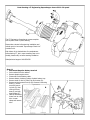
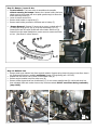
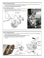
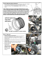
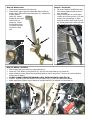
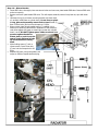
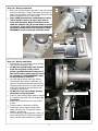
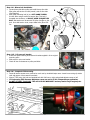
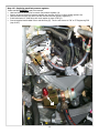
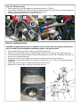
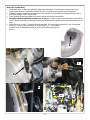
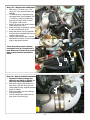
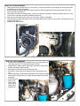
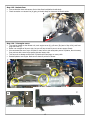
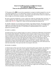
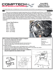
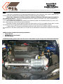
Acura 3.2CL-S
Supercharger
Installation Instructions
(2003 6-speed ONLY)
3239 MONIER CIRCLE, STE.5 • RANCHO CORDOVA, CA 95742 • 916.635.4550 • FAX 916.635.4632 • www.ct-engineering.com •
VERSION:
INS-104
6.20.2008
Thank you for purchasing the CT Engineering Supercharger Kit for the 2003 Acura 3.2CL Type-S 6 speed. All components have been designed and manufactured utilizing the latest technology and materials.
Please take a moment to read this instruction manual and warranty information page thoroughly before starting any work. CT Engineering recommends the use of a Genuine 2003 Acura 3.2CL Type-S 6-speed Service
Manual to supplement these instructions.
All CT products are intended to be installed by a professional installer. We recommend marking any hose or wire
before disconnecting to avoid confusion during reassembly.
Remember to always use jack stands to support the vehicle when a car lift is not available. Always work in a clean
environment and use the appropriate safety equipment and tools to avoid any potential damage or injuries.
**Before starting, CT Engineering recommends locating the radio code for your particular vehicle and write down
the frequencies for the radio’s preset buttons, so the radio can be reactivated and restored after completion of this installation.
Additional items needed before starting installation:
• Torque Wrench
• Sanding disc or cut-off wheel
• Size 51R battery
Installation facility; please make sure the owner of the vehicle is given a copy of the instructions and super-
1
Parts Drawing—CT Engineering Supercharger—Acura 3.2CL-S 6-speed
The CT Engineering Supercharger comes complete
with all parts shown in parts drawing.
Please take a minute before starting installation and
recheck parts in box match “Supercharger Check List”
provided in kit.
Each blower kit is checked twice for completeness
before leaving CT, but in case something was not included, please notify us before starting installation.
Sales/technical support: 916.635.4550
Step #1
• Disconnect Negative battery terminal
• Drain coolant from the radiator.
• Remove plastic engine covers.
• Disconnect Positive battery cable.
• Remove battery tie-down, battery & plastic battery tray.
• Remove stock air box lid, filter & air box bottom (A).
• Remove wiring harness from clip (B). Remove 6 mounting
bolts (C), and remove the mountA
ing bolt (D), then
remove the tray
base (E) and tray
base bracket (F).
• Label & disconnect
hoses from air inlet
tube. Loosen
clamp and remove
tube.
2
Step #2—Bumper / Lower Air box
• On most models: The lower airbox is accessible and removable
without removing the bumper. Remove the 4 screws holding the lower
splash guard to the bumper and move splash guard enough to access the
airbox mounting screws (G).
• Lower & remove stock air box
• Remove stock bracket in engine bay (E).
• Remove small rubber grommet in sub-frame next to battery (F).
•
Bumper Removal: Remove (2) screws at top corner in wheel wells (C) ,
(4) snap clips along grill top (B), (4) snap clips underneath (D) & (2)
screws at the back of bumper underneath near wheels. Slide cover (A)
forward from clips under headlights to remove cover to access stock lower
air box. (See above for airbox removal)
E
F
G
Step #3—Radiator hose
• Remove stock upper radiator hose from engine & radiator. Remove spring clamps & reuse on new silicon hose in
kit. (Replacement hoses are available exclusively through CT Engineering part # 355-155)
• Replace with new silicon hose in place of stock rubber hose (A).
• Remove engine breather hose from valve cover (B).
• Remove coolant bypass hose from throttle body (C). Do not remove manifold side (D) until throttle body has
been relocated. Mark each coolant hose as they are disconnected. DO NOT cross hoses during reassembly
(step #20-E).
A
B
D
3
C
Step #3a—Replace spark plugs
• Install new Denso IK22 Spark plugs as directed in service manual. These are a colder heat range plug and are
required to handle the extra power produced by the supercharger.
• Do not try to reset the gap on this style plug.
Step #4– Alternator harness
• Remove bolt holding plastic cover (c) over wiring harness. Open snap
clips on plastic cover & remove from wire harness.
• These wires (B) will be rerouted along groove between plastic mount
and cover.
B
B
Step #5– Preparing alternator
• Lift power steering reservoir up out of bracket on sub-frame rail and position out away from the belt assemblies.
Remove stock power steering reservoir bracket.
• Loosen stock alternator belt tensioner (C) and remove stock alternator belt (D).
• Remove lower bolt (A) on alternator then remove upper bolt (B).
• Remove bracket attached to top of alternator. These bolts will
be reused.
C
D
4
Step #6– Alternator pulley replacement
• With alternator pulley facing up remove stock alternator pulley with a 22mm &
10mm wrench (an impact gun may need to be used for removal).
• Install new alternator pulley (*See Note) and tighten nut to 81.7 ft-lbs
torque.
*Note: Honda uses two types of alternators (Delphi & Denso) on the
3.2CL-S. These have different shaft lengths. The drive pulley supplied in
your kit is designed to fit the shorter of the two shafts; there is a spacer
included in each kit that may need to be used between new pulley & nut
to ensure proper thread engagement & zero slop on drive pulley for the
alternator models with longer shaft. Test fit pulley on your alternator,
and run nut all the way down, if the pulley is not secured tight to the alternator, you will need to remove nut and install the spacer.
Step #7– Alternator
• Reinstall alternator in reverse order.
• Install new steel alternator/blower bracket on top of alternator
using factory hardware (A). Torque to specs in Step #5.
• Replace alternator belt in stock location on inner pulley (see diagram step #5).
• Twist the loom mounting bracket toward engine to properly route
wire loom (B).
• Carefully route alternator wire loom (C), along front of cam cover.
(see Step #4) Keep it clear from all belts & pulleys.
• Remove oil dip stick
and bend tube
slightly away from
B
engine so that, with
oil dipstick in place,
dipstick is on outside of wiring harness (D).
A
C
D
5
Step #8– Blower brace
• Locate upper transmission lift bracket (A).
• Install blower support (B) with slotted side down & offset towards engine. Slide bolt through steel spacer (C), transmission
bracket, second
spacer (D), slotted
bracket (B) and install
lock nut. Do not
torque yet. Torque
this bolt after installing blower and alignB
ing mount in Step
#13.
D
Step #9 - Fan shroud
• Fan shroud requires modifications keep
from rubbing against blower under engine movement.
• Using a sanding disc or cut-off wheel,
remove round corner portion of (2) main
support ribs and small top rib. Sand
these ribs to about a 45° angle, trim off
any excess plastic with a razor knife and
clean up with a smooth emery cloth.
C
A
Step #9– Battery / Overflow
• Mount battery tray using stock tray holes and bolts (A).
• Lower new “51R” battery (not supplied in kit) into tray with posts offset to inner frame rail.
• Attach Comptech battery clamp using supplied long bolt on right & long stock “J” bolt on left. Connect Positive
terminal only to battery.
• DO NOT CONNECT NEGATIVE TERMINAL UNTIL INSTALLATION IS COMPLETE! (B)
• Install CT Engineering overflow bottle on front of battery tray (C). Refill with appropriate coolant.
• Attach supplied long siphon hose to bottom of overflow bottle lid (D) and place on new bottle (C).
D
A
B
C
6
Step #11 - Blower Bracket
• Locate EGR valve, thoroughly clean area around valve and cam cover plate beside EGR valve. Remove EGR valve
and cover opening.
• Remove cam cover plate beside EGR valve. This will expose camshaft, some oil may leak out, wipe with clean
rag.
• Lubricate O-ring (A) on blower mounting bracket with clean motor
oil, carefully install plate on cylinder head. Do not force or pinch
O-ring, plate must smoothly mount flush to head. Install (2)
8mm x 35mm bolts (B) from kit and torque to 15 ft/lbs.
• Blower mount plate has a threaded spacer (C) installed in it to
make up for machining differences in production of the Honda cylinder head. Adjust this spacer to obtain light contact with cylinder
head. ( see D) DO NOT Tighten spacer. Make sure there is no
pressure against bracket to
distort plate or push it out, this
spacer is only designed to take
up inconsistencies in factory
head.
• While holding spacer (C) with a
19mm wrench, insert 10mm bolt
(E) into hole and torque bolt to 28
ft/lbs.
• Replace EGR valve, using new gasket, and
torque to 15ft/lbs. Replace electrical plug.
(8mm x 35mm)
C
7
Step #12 - Blower preparation
• Blower has (6) bolts around input shaft. Lower (4) bolts will
need to be removed*. These (4) bolt holes will be used to
attach mount to blower with the (4) longer socket bolts and
washers provided in kit (C) in step #13-B.
• Photo (A&B) shown blower upside down for clarity.
• *Note: DO NOT remove (2) upper (top) bolts on
drive shaft & housing. Bolts around blower drive
shaft also maintain seal (B) around blower’s internal
oil reservoir, if this seal is broken during installation,
the blower unit will need to be returned for a NONWARRANTY service to properly reseal the blower.
A
Bottom
Top
B
C
Step #13 - Blower installation
• Lower blower unit into position, lining up blower
with mounting bracket on head.
• DO NOT flex shaft & blower unit, this will
break the seal (Step #12-B) around
blower’s prefilled internal oil reservoir. If
this seal is broken, blower unit will need to
be returned for a NON-WARRANTY repair
to reseal blower oil reservoir.
• On pulley side of blower shaft, align blower
outer bracket with bracket on alternator. A/C
hose will route between bracket and pulley (A).
Mounting bracket should be on right-hand side
of A/C line & tensioner arm should be on lefthand side of this A/C line.
• DO NOT force A/C line to bend, this may
cause hose to leak refrigerant.
• Install (2) bolts holding blower mount to alternator bracket to align shaft with rear bracket. Do
not tighten.
• Install (4) long bolts from kit in main blower
bracket.
• Torque bracket on alternator to 15ft/lbs.
• Install upper bolt in support bracket under
blower (see step #9). Torque both ends to
15ft/lbs ( see step #5)
• Once everything is aligned properly, torque (4)
allen head bolts (B) to 10 ft/lbs and torque (2)
bolts on blower outer bracket (A) to 15ft/lbs.
Bottom
A
B
8
4th screw is located underneath.
Step #14 - Blower belt installation
• Loosen blower belt idler pulley and install blower drive belt.
Idler pulley will tension on back (smooth) side of drive belt.
(See Diagram)
• Idler pulley mounting bolt (A) is a LEFT-HAND THREAD,
this will allow using a wrench to tension idler. This bolt is
threaded into aluminum, so DO NOT OVER-TORQUE THIS
BOLT. Belt tension can be set with 25 ft/lbs of torque on this
bolt. Once belt tension is set, torque slider bolts (B) to 15ftlbs.
B
A
B
Step # 15 - P/S reservoir bracket
• Install new power steering fluid reservoir bracket supplied in kit to original
mounting point.
• Slide reservoir onto new bracket.
• Check all lines for clearance on pulley and belts.
Step #16 - Comptech FPR mounting
• Locate & remove access cover, centered on cowl vent by windshield wiper arms. Locate hose routing clip inside
cowl and remove. Move vacuum hose back.
• Mount CT FPR using this hole and supplied bolt with fuel lines on right and preload adjuster screw on left.
• CT Engineering FUEL Pressure Regulator comes pre-set for 3.2CL-S Supercharger application,
• DO NOT ATTEMPT TO ADJUST. This will VOID the WARRANTY and may lead to major engine problems.
9
Step #17— Replacing stock fuel pressure regulator.
Intake manifold DOES NOT need to be removed.
• Label and remove vacuum line from stock fuel pressure regulator (A).
• Wrap a rag around stock fuel pressure regulator and unscrew 1/4 turn to relieve system pressure (B).
• Label and remove upper fuel return line and unscrew stock fuel pressure regulator (C).
• Install red aluminum –6 AN fitting with crush washer in place of FPR (D).
• Connect supplied steel braided hose to red AN fitting (D). This line will connect to “IN” on CT Engineering FPR
(step #18-C).
A
C
B
D
10
Step #18 - FPR hose routing
• Route vacuum line from intake manifold to brass vacuum fitting on CT FPR (A).
• Use provided –6 AN fitting with rubber hose slip fit to attach outlet of FPR to hard return line. Use provided hose
clamps to secure rubber fuel hose to AN adapter and hard line (B).
• Attach stainless steel braided line to “IN” on CT FPR (C).
A
B
C
Step #19 - Installing fuel pump
CAUTION! Fuel pump will have fuel in it, make sure to have a tray to allow the pump & sending unit to
drain in. DO NOT perform installation around flame, spark or any ignition source.
•
•
•
•
•
•
•
Open trunk & fold back rear of floor carpet to access fuel tank dust cover.
Remove (3) screws holding dust cover, disconnect plug and hoses, then remove (8) bolts holding pump unit.
Remove entire pump / gauge sending unit from tank (B) and place in a tray to drain. Installation may need to be
done in tray to contain draining fuel.
Remove (H) suction filter and replace onto new pump (I) (Make sure this connection is secure).
Reassemble in reverse order, making sure to check all connections (C, D, E, F, H & I) to the housing (B) before
installation.
Check clamp at (G) to ensure no interference with wire harness (C or E).
Reinstall unit in reverse order. Torque (8) cover bolts to 36 in-lbs.
11
Step #20 -Throttle body
• Locate MAP sensor on side of throttle body, label and unplug sensor. Transfer sensor, screws and o-ring to
blower intake elbow (A). Install block off plate (B) with o-ring and screws supplied, onto throttle body.
• Prepare to transfer throttle body assembly from stock manifold, remove studs from intake manifold (D) and install studs on blower inlet in top (2) holes.
• Install supplied throttle body gasket onto intake manifold and blower inlet manifold.
• Carefully rotate throttle body so cables are on top (C). If hoses or wires restrict movement review instructions to identify what they are, label and remove to complete transfer. Replace and torque stock hardware to 14
ft/lbs.
• Route both new 10” and 17” coolant lines to throttle body. 10” line connects horizontal line out of thermostat
housing (E) to side (previously bottom) of throttle body (F), 17” line connects
vertical line out of thermostat housing (G) to face of throttle body facing firewall (H).
A
C
B
G
D
17”
E
10”
F
12
H
Step # 21 - Wire harness modification
• MAP sensor / TP sensor (A-1) / IAC
valve (A-2) wire loom will need to be
modified.
• Cut electrical tape* wrapped around
corrugated loom (A) and separate TPS
(1) & IACV (2) plugs from MAP plug
until they are long enough to reach
TPS, IACV & MAP sensors.
• Route TPS plug to new sensor location
under throttle body (B-1).
• Route IACV plug to new sensor location
on side of throttle body (B-2).
• Route MAP sensor wire to intake manifold inlet where relocated MAP sensor is
installed (Step #20-A).
• Using a good electrical tape, wrap the
exposed wire and loom. Connect sensor
plugs to appropriate sensors.
2
A
1
*Note: Use caution when trimming
corrugated loom (A). Sharp knives or
razor blades can cut into wires, potentially causing electrical problems in
future.
2
B
1
Step #22 - Blower manifold installation
• Inspect all intake openings and
tubes for any debris or objects. Install only clean inspected parts.
• Slide silicon coupler and clamps on intake elbow. Bolt cast elbow (A) onto
intake manifold using supplied hardware,
torque to 14ft/lbs.
• Slide hose equally over both housings
and tighten clamps.
• Connect vacuum hose from blower bypass valve to inlet fitting (B).
B
A
13
Step # 23 - Icebox installation
• Locate ground wire on fender-well in air box area (B), remove bolt. Remove clips holding wire loom along fender
to relocate wire for Icebox clearance.
• Remove 3-hole mounting bracket from Icebox and bolt in place with ground wire using ground bolt (B). Leave
loose until Icebox is attached.
• Place Icebox in fenderwell, making sure it is slid over as closely as possible to battery tray edge. Align hole in bottom to hole in sub-frame and start provided 8 mm bolt (A).
• Align box with side bracket (B) & insert (2) 8 mm bolts. Tighten all hardware.
• From inside lower fender-well slide air horn over airbox bottom inlet. Orient air inlet so open end faces front of car.
Tighten band clamp (C).
• Reinstall front bumper cover.
B
C
A
Step # 24 - Filter installation
• Prepare filter by coating it with supplied filter oil (For future filter services order service kit: CT Engineering part# 620-004)
• Assemble filter, adaptor elbow, large bellows, extension elbow, small
bellows and clamps( loosely clamp).
• Place small end of bellows over throttle body inlet.
• Place filter in Icebox with front alignment post in alignment groove
(A).
• Confirm alignment of all pieces and clearance of large bellows to ABS
sensor plug on shock tower (B). Tighten all band clamps and recheck
alignment.
• Install Icebox lid.
• Route cruise
control cable
along side of
Icebox using
supplied clip.
B
A
14
Step # 25 - Recheck lines
• Connect breather hose and vacuum line to inlet elbow barb before throttle body.
• Check connection on vacuum line (A) going to throttle body for clearance on throttle cables.
A
Step # 26 - Trim engine covers
• Trim engine plastics to clear blower unit; main engine cover (A), grill cover (B) (seen in Step #2-A), and front
plug wire cover (C).
• Below is an example of where to trim, but you will have to test fit yours to ensure proper fitment.
• We recommend the use of a cut off wheel or razor knife to trim away main portion of plastics, then trim away
finer portions with a razor knife, sanding disc and emery cloth.
• Take care not to damage surface finish of plastics with sand paper or emery cloth.
• Reinstall plastics onto engine. Make sure it clears all portions of blower.
A
B
15
Step # 27 - Installing ESM unit
• Please refer to the instructions included with the ESM unit for wiring & installation.
Step# 28 Final
• Place CARB EO Decal in a visible place within the engine bay for inspection purposes.
• Refill radiator.
•
COOLING SYSTEM MUST BE PROPERLY BLEED AS DIRECTED IN SERVICE MANUAL,
•
FAILURE TO DO SO COULD RESULT IN ENGINE DAMAGE.
• Recheck all connections, fittings, fluids, plugs and wires. Wipe down all parts.
• Replace negative battery terminal.
• Turn ignition key to the “ON” position but DO NOT START ENGINE. This will allow the fuel pump to pressurize
the system. Check all fuel lines for leaks.
• Start vehicle, check for any leaks, squeaks or rubbing of components.
• After car has cooled recheck coolant level, belt tension / alignment and leaks.
...Enjoy the Drive!
16
Installation facility; please make sure the owner of the vehicle is given this page, along with a copy of
the instructions for their records.
Honda/Acura V6 Supercharger Maintenance
Filter maintenance:
• Inspect air filter during normal oil servicing intervals (every 3000 miles or 3 months).
• Filter will normally need cleaning/re-oiling about every other regular oil change, but may vary due climate/
regional differences.
• When in doubt about servicing, remember a clean filter flows more air, and will allow your vehicle to run better.
• Properly maintained, the included filter should last the lifetime of your vehicle.
• For future filter service, please order CT/Uni Filter Service kit: Part# 620-004
Belt Maintenance:
• Inspect and replace worn belt when inspecting all other rubber belts as per the Honda/Acura service schedule.
• Blower Drive Belt Replacement: Part# 350-058 (2003 CL-S 6-spd) or # 350-059 (98-02 Accord V6)
Blower Maintenance:
• Sound from the blower unit is normal at idle and normal operating conditions.
• Blower unit should not require any servicing for 70,000+ miles.
• If blower unit shows signs of wear or defect, i.e. oil leaking, excessive sound, or damaged unit, please contact
CT Engineering for information on repair facilities.
Misc Maintenance:
• Remember to check all hoses, vacuum lines, electrical connections, battery, etc, whenever servicing vehicle, to
ensure proper vehicle operation.
17