1
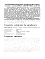
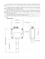
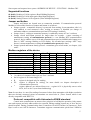
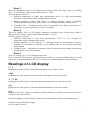
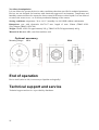
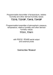
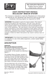
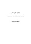
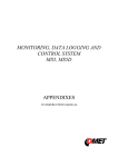
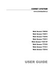
TRANSMITTER TR485-103D-150, TR485103D-700
Programmable transmitter of temperature, relative humidity
and other derived humidity values with RS485 serial output
Instruction Manual
Instruction Manual for use of temperature and relative
humidity transmitter TR485-103D-150, TR485-103D-700
Transmitter is designed for measurement of air temperature at °C or °F and relative humidity
of air without aggressive ingredients with computing one of the following values: dew point
temperature, absolute humidity, specific humidity, mixing ratio and specific enthalpy. Please read
instruction manual before the first transmitter connection. Transmitter communicates via
link RS485. Supported communication protocols are Modbus RTU, protocol compatible with
standard Advantech-ADAM and ARION. Temperature and relative humidity sensors are nonremovable instrument parts. Measured and computed values are displayed on dual line LCD
display. The first line displays temperature. Value displayed on the second line is selectable among
relative humidity and computed value. It is also possible to display both readings with cyclic
overwriting in 4 seconds interval. Display can be also switched OFF totally. Output link RS485 is
galvanic isolated. Please read instruction manual before the first device connection.
Use user’s software Tsensor for setting of all device parameters (recommended). It
supports make the adjustment of the device too. This procedure is described at file „Calibration
manual.pdf“ which is installed commonly with the software. Change of some parameters is possible
to do without user’s software with Windows hyperterminal (change of communication protocol, its
parameters, LCD display setting). It is described in file “Description of communication protocols of
Txxxx series” which is free to download at the same address.
Transmitter setting from the manufacturer
If special setting was not required in the order, transmitter is set from the manufacturer to the
following parameters:
communication protocol:
transmitter address:
communication speed:
display:
value displayed at lower line:
preset computed value:
Modbus RTU
01H
9600Bd, without parity, 2 stop bits
switched ON
relative humidity only
dew point temperature
Transmitter installation
Transmitter is designed for air-conditioning duct – metal stem fixed by means of the
optional gland. Also optional installation flanges PP4 or PP90 are possible to use (not included in
delivery). Measuring temperature and relative humidity sensors are non-removable instrument parts.
It is NOT recommended to use the device for long time under condensation conditions. It could be
the cause of water steam condensation inside the sensor’s cover into water phase. This liquid phase
stays inside sensor’s cover and can’t escape from the cover easily. It can dramatically increase
response time to relative humidity change. If water condensation occurs for longer time it can cause
sensor damage. Similar effect can occur under water aerosol conditions. If this effect may occur, it
is necessary to use the device at operation position with sensor cover downwards. Don’t connect
transmitter while power supply voltage is on. Interconnection terminals are accessible after
unscrewing four screws and removing the lid. Lace the cable through a gland at the case wall.
Connect the cable to terminals with respecting the signal polarity (see figure). Terminals are selfclamping and can be opened by a suitable screwdriver. For the opening, insert the screwdriver to
smaller terminal hole and lever by him. Do not forget to tighten glands and case lid with inserted
packing after cables connecting. It is necessary for warranting of protection IP65.
2
It is recommended to use shielded twisted copper cable (e.g. SYKFY ). Outside diameter of the
cable must be from 3 to 6.5 mm, maximal length 1200m. The cable must be located at indoor
rooms.
Nominal cable impedance should be 100 Ω, loop resistance max. 240 Ω, cable capacity max.
65 pF/m. Suitable cable is e.g. SYKFY 2x2x0,5 mm2, where one wire pair serves for transmitter
powering and the other pair for communication link.
The cable should be led in one line, i.e. NOT to „tree“ or „star“. Termination resistor should
be located at the end. For short distance other topology is allowed. Terminate the network by a
termination resistor. The value of the resistor is recommended about 120 Ω. For short distance
termination resistor can be left out.
The cable should not be led in parallel along power cabling. Safety distance is up to 0.5 m,
otherwise undesirable induction of interference signals can appear.
Electrical system (wiring) may do only worker with required qualification by rules in
operation.
Dimensions
3
Typical application wiring, connection of terminals
Info mode
If in doubt of setting of installed transmitter, verification of its address is enabled even
without using computer. Power should be connected.
Unscrew transmitter cover and shortly press button next to connection terminals (jumper
should be opened). Actual adjusted address of transmitter is displayed on LCD display at decimal
base. Next press of button exits info mode and actual measured values are displayed.
Note: No measurement and communication is possible during info mode. If transmitter stays in info
mode for longer than 15 s, transmitter automatically returns to measuring cycle.
Description of communication protocols
Detailed description of each communication protocols including examples of
communication is available in individual document “Description of communication protocols of
Txxxx series”.
Note: After switching ON the power of the device it can last up to 2 s before the device starts to
communicate and measure!
Modbus RTU
Control units communicate on master-slave principle in half-duplex operation. Only master
can send request and only addressed device responds. During sending of request no other slave
station should respond. During communication, data transfer proceeds in binary format. Each Byte
is sent as eight bit data word in format: 1 start bit, data word 8 bit (LSB first), 2 stop bits1, without
parity. Transmitter supports communication speed from 110Bd to 115200Bd.
1
4
Transmitter sends two stop bits, for receive one stop bit is enough.
Sent request and response have syntax: ADDRESS OF DEVICE – FUNCTION – Modbus CRC
Supported functions
03 (0x03): Reading of 16-bit registers (Read Holding Registers)
04 (0x04): Reading of 16-bit input gates (Read Input Registers)
16 (0x10): Setting of more 16-bit registers (Write Multiple Registers)
Jumper and button
Jumper and button are located next to connection terminals. If communication protocol
Modbus is selected the function of jumper and button is as follows:
• Jumper opened – transmitter memory is protected from writing, from transmitter side it is
only enabled to read measured value, writing to memory is disabled (no change of
transmitter address, communication speed and LCD setting is enabled)
• Jumper closed – writing to transmitter memory is enabled by means of User’s software
• Jumper closed and button pressed for longer than six seconds – causes restoring of
manufacturer setting of communication protocol, i.e. sets Modbus RTU communication
protocol, device address sets to 01h and communication speed to 9600Bd (after button press
there is “dEF” message blinking at LCD display. Six seconds later message “dEF” stays
shown, it means manufacturer setting of communication protocol is done).
• Jumper opened and button shortly pressed – transmitter goes to Info mode, see chapter „Info
mode“
Modbus registers of the device
Variable
Unit
AddressX Format Size
Status
Measured temperature
[°C]
0x0031
Int*10
BIN16
R
Measured relative humidity
[%]
0x0032
Int*10
BIN16
R
*
Computed value
[°C]
0x0033
Int*10
BIN16
R
Address of transmitter
[-]
0x2001
Int
BIN16
R/W*
Code of communication speed
[-]
0x2002
Int
BIN16
R/W*
Serial number of transmitter Hi [-]
0x1035
BCD
BIN16
R
Serial number of transmitter Lo [-]
0x1036
BCD
BIN16
R
Version of Firmware Hi
[-]
0x3001
BCD
BIN16
R
Version of Firmware Lo
[-]
0x3002
BCD
BIN16
R
Explanation:
• * to choice of computed value type use User’s software
• Int*10 register is in format integer*10
• R
register is designed only for reading
• W*
register is designed for writing, for more details see chapter description of
communication protocols
• X
register addresses are indexed from zero – register 0x31 is physically sent as value
0x30, 0x32 as 0x31 (zero based addressing)
Note: In case there is a need for reading of measured values from transmitter with higher resolution
than one decimal, measured values in transmitter are stored also in „Float“ format, which is not
directly compatible with IEEE754.
Protocol compatible with Advantech-ADAM standard
Control units communicate on master-slave principle in half-duplex operation. Only master
can send requests and only addressed device responds. During sending request any of slave devices
should respond. During communication data is transferred in ASCII format (in characters). Each
Byte is sent as two ASCII characters. Transmitter supports communication speed from 1200Bd to
5
115200Bd, parameters of communication link are 1 start bit + eight bit data word (LSB first) +
1 stop bit, without parity.
Jumper
Jumper is located next to connection terminals. If communication protocol compatible with
standard Advantech-ADAM is selected, its function is the following:
• If jumper during switching ON the power is closed, transmitter always communicates with
following parameters regardless stored setting in the transmitter:
communication speed 9600 Bd, without check sum, transmitter address 00h
• If jumper during switching ON the power is not closed, transmitter communicates in
accordance with stored setting.
• If jumper is closed during transmitter operation, transmitter temporarily changes its address
to 00h, it will communicate in the same communication speed as before closing jumper and
will communicate without check sum. After jumper is opened setting of address and check
sum is reset in accordance with values stored in transmitter.
• Communication speed and check sum are possible to change only if jumper is closed.
• Jumper closed and button pressed for longer than six seconds – causes restoring of
manufacturer setting of communication protocol, i.e. sets Modbus RTU communication
protocol, device address sets to 01h and communication speed to 9600Bd (after button press
there is “dEF” message blinking at LCD display. Six seconds later message “dEF” stays
shown, it means manufacturer setting of communication protocol is done).
For communication with device which measure more than one value, there is necessary to add at
the end of command, number of communication channel, where the measured value is mapped.
Command for value reading is #AAx(CRC) CR, where AA is device address and x is number of
communication channel by next table:
Measured value
Temperature
Relative humidity
Computed value
Number of communication
channel
0
1
2
ARION communication protocol
The device supports communication protocol ARiON version 1.00. For more details see file
“Description of communication protocols of Txxxx series”.
Error States of the device
Device continuously checks its state during operation. In case error is found LCD displays
corresponding error code:
Error 0
First line displays „Err0“.
Check sum error of stored setting inside device’s memory. This error appears if incorrect writing
procedure to device’s memory occurred or if damage of calibration data appeared. At this state
device does not measure and calculate values. It is a serious error, contact distributor of the
instrument to fix.
6
Error 1
Measured (calculated) value is over upper limit of allowed full scale range. There is a reading
„Err1“ on LCD display. Value read from the device is +999,9.
This state appears in case of:
• Measured temperature is higher than approximately 600°C (i.e. high non-measurable
resistance of temperature sensor, probably opened circuit).
• Relative humidity is higher than 100%, i.e. damaged humidity sensor, or humidity
calculation of humidity is not possible (due to error during temperature measurement)
• Computed value – calculation of the value is not possible (error during measurement of
temperature or relative humidity or value is over range)
Error 2
There is a reading „Err2“ on LCD display. Measured (calculated) value is below lower limit of
allowed full scale range. Value read from the transmitter is -999,9.
This state appears in case of:
• Measured temperature is lower than approximately -210°C (i.e. low resistance of
temperature sensor, probably short circuit).
• Relative humidity is lower than 0%, i.e. damaged sensor for measurement of relative
humidity, or calculation of humidity is not possible (due to error during temperature
measurement)
• Computed value – calculation of computed value is not possible (error during measurement
of temperature or relative humidity)
Error 3
There is a reading „Err3“ on LCD display upper line.
Error of internal A/D converter appeared (converter does not respond, probably damage of A/D
converter). No measurements proceed. It is a serious error, contact distributor of the instrument.
Readings on LCD display
°C, °F
Reading next to this symbol is measured temperature or error state of value.
%RH
Reading next to this symbol is measured relative humidity or error state of value.
°C / °F DP
Reading next to this symbol is calculated dew point temperature or error state of value.
g/m3
Reading next to this symbol is calculated absolute humidity or error state of value.
g/kg
Reading next to this symbol is calculated specific humidity or mixing ratio (depends on device
setting) or error state of value.
If specific enthalpy is selected, there is shown only value (number) without corresponding unit!
symbol 3 near by left display margin
Is on if jumper is closed.
7
Technical parameters of the instrument:
RS 485 Interface:
Receiver-Input Resistance:
Devices on bus:
96 kΩ
max. 256 (1/8 Unit Receiver Load)
Measuring parameters:
Ambient temperature (RTD sensor Pt1000/3850ppm):
Measuring range:
-30 to +125 °C
Resolution of display:0.1 °C
Accuracy:
± 0.4 °C
Relative humidity (reading is temperature compensated at entire temperature range):
Measuring range:
0 to 100 %RH (see Transmitter installation)
Resolution display: 0.1 %RH
Accuracy:
± 2.5 %RH from 5 to 95 %RH at 23 °C
Measuring temperature and humidity range is limited in accordance with the graph
below
8
The value computed from ambient temperature and relative humidity:
Display resolution: 0,1 °C
You can choice one of the next value:.
Dew point temperature
Accuracy:
±1,5 °C at ambient temperature T < 25°C and RH >30%
Range:
-60 to +80 °C
Absolute humidity
Accuracy:
±3g/m3 at ambient temperature T < 40°C
Range:
0 to 400 g/m3
Specific humidity2
Accuracy:
Range:
±2g/kg at ambient temperature T < 35°C
0 to 550 g/kg
Mixing ratio
Accuracy:
Range:
±2g/kg at ambient temperature T < 35°C
0 to 995 g/kg
Specific enthalpy
Accuracy:
± 3kJ/kg at ambient temperature T < 25°C
Range:
0 to 995 kJ/kg 3
Response time with stainless steel mesh sensor cover (F5200) and bronze sensor cover
(F0000 - selectable option), air flow approximately 1 m/s:
temperature: t90 < 9 min (temperature step 20 °C)
relative humidity: t90 < 30 s (humidity step 65 %RH, constant temperature)
Recommended calibration interval: 1 year
Measuring interval and LCD display refresh: 0.5 s
Power: 9 to 30 V dc
Consumption: max. 0.5W
Protection of the case with electronics and terminals:
Protection of the sensor cover:
IP65
IP40
Filtering ability of the sensor cover: 0.025 mm
Operating conditions:
Operating temperature range of case with electronics: -30 to +80 °C, over +70°C switch
LCD display OFF
Operating temperature range measuring tip with sensors: -30 to +125 °C
Operating relative humidity range: 0 to 100 %RH
Outer influence in accordance with EN 33-2000-3: normal environment with those
specifications: AE1, AN1, AR1, BE1
Working position: in air-conditioning duct arbitrary, in free space the steel stem downwards
(see Transmitter installation)
Electromagnetic compatibility: complies EN 61326-1
2
This value depends on the atmospheric pressure. For computing is used constant value stored
inside device memory. Default value preset by manufacturer is 1013hPa and can be changed by
user’s software.
3
This maximum is reached under conditions about 70°C/100%RH or 80°C/70%RH
9
Not allowed manipulation
It is not allowed to operate the device under conditions other than specified in technical parameters.
Devices are not designed for locations with chemically aggressive environment. Temperature and
humidity sensors must not be exposed to direct contact with water or other liquids. It is not allowed
to remove the sensor cover—to avoid any mechanical damage of the sensors.
Storing conditions: temperature -30 to +80 °C, humidity 0 to 100 %RH without condensation
Dimensions: case with electronics 89x73x37 mm, length of stem 150mm (TR485-103D150)/700mm (TR485-103D-700)
Weight: TR485-103D-150 approximately 250 g, TR485-103D-700 approximately 600 g
Material of the case: ABS, stem from stainless steel
Optional accessory
Mounting flanges:
PP4
End of operation
Device itself (after its life) is necessary to liquidate ecologically!
Technical support and service
Technical support and service is provided by distributor.
10
PP90
Appendix A
Connection of ELO E06D converter (RS232/RS485)
(optionally accessory of the transmitter TR485-103D-700)
The ELO E06D converter is an optional accessory for connection of transmitter/transmitters with
RS485 interface to the PC via serial port RS232. Connect connector marked RS232 directly to the
PC, connect power to connector marked RS485. Power voltage +6V DC from an external acdc
adapter connect to pin 9, 0V connect to pin 5. Also mutually connect pin 2 and pin 7. Link RS485
is connected across pin 3 (A+) and pin 4 (B-).
11