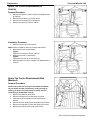
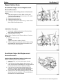
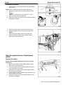
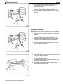
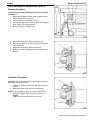
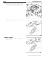
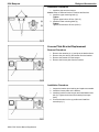
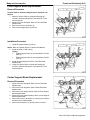
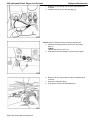
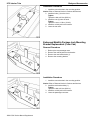
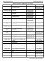
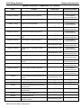
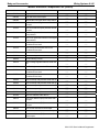
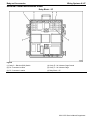
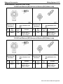
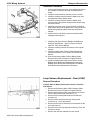
1
Preface
Preface P-1
Preface
CAUTION
Caution: In order to reduce the chance of personal injury and/or property damage, carefully
observe the instructions that follow:
The service manuals of General Motors Corporation are intended for use by professional,
qualified technicians. Attempting repairs or service without the appropriate training, tools,
and equipment could cause injury to you or others. This could also damage the vehicle, or
cause the vehicle to operate improperly.
Proper vehicle service and repair are important to the safety of the service technician and to
the safe, reliable operation of all motor vehicles. If you need to replace a part, use the same
part number or an equivalent part. Do not use a replacement part of lesser quality.
The service procedures we recommend and describe in this service manual are effective
methods of performing service and repair. Some of the procedures require the use of tools
that are designed for specific purposes.
Accordingly, any person who intends to use a replacement part, a service procedure, or a
tool that is not recommended by General Motors, must first establish that there is no
jeopardy to personal safety or the safe operation of the vehicle.
This manual contains various “Cautions” and “Notices” that you must observe carefully in
order to reduce the risk of personal injury during service or repair. Improper service or
repair may damage the vehicle or render the vehicle unsafe. These “Cautions” and “Notices”
are not exhaustive. General Motors can not possibly warn of all the potentially hazardous
consequences of your failure to follow these instructions.
This manual covers service procedures to vehicles that are equipped with a Supplemental
Inflatable Restraint (SIR). Refer to the “Cautions” in Cautions and Notices and in Restraints.
Refer to SIR component and wiring location views in Restraints before performing a service
on or around SIR components or wiring. Failure to follow these “Cautions” could cause air
bag deployment, personal injury, or otherwise unneeded SIR repairs.
In order to help avoid accidental air bag deployment and personal injury, whenever you
service a vehicle that requires repair of the SIR and another vehicle system, we recommend
that you first repair the SIR, then go on to the other system.
Preface P-2
Preface
2006 General Motors LSSV/EMP Trucks Service Manual Supplement
Volume 1
This manual provides information on the diagnosis, the service procedures, the adjustments, and the specifications for
the 2006 General Motors LSSV/EMP Trucks.
Information on transmission unit repair (overhaul) can be found in the 2006 Transmission/Transaxle/Unit Repair Manual
(TURM), available separately. The TURM contains information on automatic and manual transmissions, including the
fluid flow and circuit description information.
The technicians who understand the material in this manual and in the appropriate Dealer Service Bulletins better serve
the vehicle owners.
When this manual refers to a brand name, a part number, or a specific tool, you may use an equivalent product in place
of the recommended item. All information, illustrations, and specifications in this manual are based on the latest product
information available at the time of publication approval. General Motors reserves the right to make changes at any time
without notice.
Published by
GM DEFENSE MILITARY TRUCKS
General Motors Corporation
Detroit, Michigan 48265-1000
www.gmfleet.com
©2006 GENERAL MOTORS CORPORATION
ALL RIGHTS RESERVED
The information cutoff date is 8/11/06
LITHO IN U.S.A.
PART NO. LSSVSM06P
No part of this manual may be reproduced, stored in any retrieval system, or transmitted in any form or by any means
(including but not limited to electronic, mechanical, photocopying, and recording) without the prior written permission of
General Motors Corporation. This applies to all text, illustrations and tables.
Preface
Preface P-3
BLANK
Cautions and Notices P-4
Preface
Cautions and Notices
Fastener Notice
Battery Disconnect Caution
Notice: Use the correct fastener in the correct location.
Replacement fasteners must be the correct part
number for that application. Fasteners requiring
replacement or fasteners requiring the use of thread
locking compound or sealant are identified in the
service procedure. Do not use paints, lubricants, or
corrosion inhibitors on fasteners or fastener joint
surfaces unless specified. These coatings affect
fastener torque and joint clamping force and may
damage the fastener. Use the correct tightening
sequence and specifications when installing fasteners
in order to avoid damage to parts and systems.
Caution: Before servicing any electrical
component, the ignition key must be in the OFF or
LOCK position and all electrical loads must be OFF,
unless instructed otherwise in these procedures. If
a tool or equipment could easily come in contact
with a live exposed electrical terminal, also
disconnect the negative battery cable. Failure to
follow these precautions may cause personal injury
and/or damage to the vehicle or its components.
Vehicle Lifting Caution
Caution: To avoid any vehicle damage, serious
personal injury or death when major components
are removed from the vehicle and the vehicle is
supported by a hoist, support the vehicle with jack
stands at the opposite end from which the
components are being removed.
Table of Contents
Table of Contents 1
Table of Contents
Preface
General Information
General Information.................................................0-3
Maintenance and Lubrication ..................................0-7
Steering
Power Steering System...........................................2-3
Suspension
Front Suspension ....................................................3-3
Rear Suspension.....................................................3-9
Tires and Wheels ................................................. 3-17
Tire Pressure Monitoring ...................................... 3-35
Body and Accessories
Body Front End ....................................................... 8-3
Body Rear End........................................................ 8-7
Bumpers................................................................ 8-17
Exterior Trim ......................................................... 8-29
Frame and Underbody.......................................... 8-33
Horns .................................................................... 8-47
Instrument Panel, Gages and Console................. 8-53
Interior Trim........................................................... 8-67
Lighting Systems .................................................. 8-79
Paint/Coatings..................................................... 8-121
Seats................................................................... 8-125
Wiring Systems ................................................... 8-129
INDEX ............................................................. INDEX-1
Driveline/Axle
Front Drive Axle.......................................................4-3
Rear Drive Axle .......................................................4-5
Transfer Case – NVG 261-NP2 ..............................4-7
Brakes
Disc Brakes .................................................................5-3
Engine
Engine Electrical......................................................6-3
Engine Controls – 6.6L (LBZ)............................... 6-43
2006 LSSV Service Manual Supplement
2
Table of Contents
2 Table of Contents
BLANK
2006 LSSV Service Manual Supplement
General Information
Table of Contents 0-1
Section 0
General Information
General Information..................................0-3
Introduction ..........................................................0-3
Vehicle Identification...........................................0-3
RPO Code List....................................................0-4
LSSV Equipment Options ...................................0-5
LSSV Labels .......................................................0-5
Maintenance and Lubrication ..................0-7
Specifications .......................................................0-7
Capacities – Approximate Fluid..........................0-7
Fluid and Lubricant Recommendations ............. 0-7
Tire Inflation Pressure ........................................ 0-7
Tire Pressure Monitoring System Settings
(EMP Only)......................................................... 0-8
Maintenance Items............................................. 0-8
Maintenance ......................................................... 0-8
Maintenance Schedule....................................... 0-8
Owner Checks and Services.............................. 0-8
Periodic Maintenance Inspection ....................... 0-8
2006 LSSV Service Manual Supplement
0-2 Table of Contents
General Information
BLANK
2006 LSSV Service Manual Supplement
General Information
General Information
General Information 0-3
Cargo/Troop Carrier Base
Introduction
Vehicle Identification
The 2006 LSSV series pickup models derive from
standard commercial vehicles. The pickup is a 2500HD,
or “9200 lb GVW” based pickup.
The pickup vehicles have rugged designs intended for
all types of roads or infrequent off-road travel. They can
ford water obstacles for three minutes without stalling at
depths of 51 cm (20 in) at 8 kph (5 mph). These limits
are met without causing permanent damage or
requiring immediate maintenance.
The pickup vehicles are equipped with heavy duty
shocks front and rear, 4-wheel anti-lock brakes, a
locking differential, on-off road tires, front and rear Drings and blackout (B/O) lighting.
A slave receptacle is mounted on the front of the
vehicles, protected by a radiator brush guard.
Cargo Carrier Crew Cab
Pickup Vehicle Information
The pickup vehicles are equipped with a 6.6L Turbo
diesel engine with a 5-speed Allison automatic
transmission and 2-speed transfer case. Payload
capacity is not to exceed the gross axle weight rating of
the front and rear axle.
The pickup has a cargo cover and troop seating for up
to eight or a hard cap with opening windows. A
specially upgraded electrical system can handle 24V
communications equipment and charging of the 24V
battery.
Cargo Carrier Base
Cargo/Troop Carrier Crew Cab
2006 LSSV Service Manual Supplement
0-4 General Information
General Information
RPO Code List
RPO Table
RPO
Description
The production/process codes provide the description
of the LSSV Option.
APF
Troop Seats with Canvas Top
BNA
Optima Battery (LSSV only)
EM7
Enhanced Mobility Package
MNB
Military Upfit
PPG
Green Flat Paint (LSSV only)
PPT
Tan Flat Paint (LSSV only)
PUC
Pickup Cap with Bumper Mounted
Swing Away Spare Tire Carrier
2006 LSSV Service Manual Supplement
General Information
General Information 0-5
LSSV Equipment Options
LSSV Labels
2006 Light Service Support Vehicle – LSSV
Specifications/Options
Your vehicle may have some or all of the following
labels.
Your vehicle may be equipped with any combination of
the following options.
Vehicle Load Disconnect Switch Caution
Label
LSSV Equipment Options
Description
Blackout (B/O) Lighting
Slave Start
Rear D-Rings
Pintle Hook
Trailer Light Connection
Gun Rack
Transfer Case/Differential Vent Filters
Government Data Plate
Cargo Area Troop Seats
Cargo Cover (Soft-Top)
Combination Front or Rear Mounted Winch Prep
Cargo Locking Side/Rear Access Fiberglass Top
Pioneer Tool Kit
Heavy Duty Front Bumper with Brush Guard and
D-Rings
Heavy Duty Rear Bumper with D-Rings and Receiver
Hitch
If the vehicle is equipped with a load disconnect switch,
the switch disconnects 12-volt vehicle loads and 24-volt
trailer/aux loads that could cause a parasitic drain on
the batteries.
The switch should be placed in the OFF position when
the vehicle is parked for an extended period of time.
The load disconnect switch is located under the
accessory panel.
24V System
Enhanced Suspension
Tire Pressure Monitoring System
Beadlock Tires
Interior Air Cleaner Restrictor Gage
AGM (Absorbed Glass Mat) Battery (Optima)
2006 LSSV Service Manual Supplement
0-6 General Information
24V Battery Caution Label
The 24V battery caution label is placed on top of the
radiator support near the 24V battery. This battery is
on the left side of the engine compartment.
Vehicle Identification Plate
The vehicle identification plate is located on the left
front inner door panel under the shipping data plate.
This plate includes the identification number, contract
number and vehicle variant.
2006 LSSV Service Manual Supplement
General Information
Shipping Data Plate
The shipping data plate is located on the left front inner
door panel above the vehicle identification plate. This
plate includes the loading and dimensions.
General Information
Maintenance and Lubrication 0-7
Fluid and Lubricant
Recommendations
Maintenance and
Lubrication
The Recommended Fluids and Lubricants information
will be found in the Owners Manual and Owners
Manual Supplement. Refer to the Maintenance
Schedule subsection of the Owners Manual.
Specifications
Capacities – Approximate Fluid
See Fluid and Lubricant Recommendations for more
information. All capacities are approximate. When
adding, be sure to fill to the approximate level, as
recommended in this manual. Recheck fluid level after
filling.
Tire Inflation Pressure
Specifications
Important: These pressures and specifications are for
Enhanced Mobility Package (EMP) or RPO EM7 only.
Tire Inflation Pressure Specifications* (EMP Only)
Terrain
Deflection
Maximum Speed
Load
Minimum Inflation
Highway ** Front Axle
—
149 km/h (93 mph)
1089 kg (2400 lbs)
3.10 Bar (45 PSI)
Highway ** Rear Axle
—
149 km/h (93 mph)
1390 kg (3042 lbs)
4.48 Bar (65 PSI)
Highway ***
18%
149 km/h (93 mph)
1043 kg (2300 lbs)
2.76 Bar (40 PSI)
Cross Country ***
25%
48 km/h (30 mph)
1043 kg (2300 lbs)
1.59 Bar (23 PSI)
Mud, Sand, Snow ***
30%
16 km/h (10 mph)
1043 kg (2300 lbs)
1.24 Bar (18 PSI)
* Option Package EMP (Enhanced Mobility Package)
vehicles only. Non-EMP vehicles refer to the Tire and
Loading Information label attached to the vehicles
center pillar (B-pillar), below the driver’s door lock post
(striker).
** Inflation pressure needed to obtain the Gross Vehicle
Weight Rating (GVWR).
*** All Axles
2006 LSSV Service Manual Supplement
0-8 Maintenance and Lubrication
General Information
Tire Pressure Monitoring System Settings (EMP Only)
Tire Pressure and Slope
Terrain
Cold Inflation Pressure
Slope
Highway * Front Axle
3.10 Bar (45 PSI)
55
Highway * Rear Axle
4.48 Bar (65 PSI)
75
Highway **
2.76 Bar (40 PSI)
51
Cross Country **
1.60 Bar (23 PSI)
34
Mud, Sand, Snow **
1.24 Bar (18 PSI)
29
Tire Pressure and Slope
Terrain
Deviation Pressure Alert ***
Low Pressure Warning
Highway * Front Axle
0.34 Bar (±5 PSI)
2.28 Bar (33 PSI)
Highway * Rear Axle
0.34 Bar (±5 PSI)
2.76 Bar (40 PSI)
Highway **
0.34 Bar (±5 PSI)
2.07 Bar (30 PSI)
Cross Country **
0.34 Bar (±5 PSI)
1.17 Bar (17 PSI)
Mud, Sand, Snow **
0.34 Bar (±5 PSI)
0.90 Bar (13 PSI)
* Factory Tire Pressure Setting
** All Axles
*** From Cold Pressure Tire Setting
Maintenance Items
The Normal Maintenance Replacement Parts
information will be found in the Owners Manual and
Owners Manual Supplements. Refer to the
Maintenance Schedule subsection of the Owners
Manual.
If the concern still has not been corrected, shut down
the engine and notify your maintenance unit or
dealership.
Periodic Maintenance Inspection
•
Inspect the condition of the headlamps,
taillamps, turn signals, side lamps, and blackout
(B/O) lamps before beginning to operate the
vehicle each time.
•
Inspect the axle vent tube filter for blockages
every six months and more often when difficult
off-road conditions are encountered. Replace as
needed.
Refer to Front Axle Vent Tube Filter
Replacement in Front Drive Axle or Rear Axle
Vent Tube Filter Replacement in Rear Drive
Axle.
•
Inspect the transfer case vent tube filter for
blockages every six months and more often
when difficult off-road conditions are
encountered.
Replace as needed. Refer to Transfer Case
Vent Tube Filter Replacement in Transfer Case
NVG 261-NP2.
Maintenance
Maintenance Schedule
The Maintenance Schedule information will be found in
the Owners Manual and Owners Manual Supplement.
Refer to the Maintenance Schedule subsection of the
Owners Manual.
Owner Checks and Services
If the engine, controls, instruments or gages do not
operate as described in this supplement manual, refer
to one of the following manuals:
•
2006 C/K Truck Owners Manual
•
2006 C/K Truck Service Manual
•
2006 Diesel Engine Owners Manual
Supplement
•
2006 LSSV Owners Manual Supplement
2006 LSSV Service Manual Supplement
Steering
Table of Contents 2-1
Section 2
Steering
Power Steering System............................ 2-3
Specifications .......................................................2-3
Repair Instructions...............................................2-4
Power Steering Pump Heat Shield
Replacement.......................................................2-4
2006 LSSV Service Manual Supplement
2-2 Power Steering
Steering
BLANK
2006 LSSV Service Manual Supplement
Steering
Power Steering System 2-3
Power Steering System
Specifications
Fastener Tightening Specifications
Specification
Application
Power Steering Pump Heat Shield Bolts
Metric
English
8 N•m
71 lb in
2006 LSSV Service Manual Supplement
2-4 Power Steering System
Steering
Repair Instructions
Power Steering Pump Heat Shield
Replacement
Removal Procedure
Caution: Refer to Vehicle Lifting Caution in Cautions and
Notices.
1. Raise the vehicle. Refer to Lifting and Jacking the
Vehicle in General Information in 2006 C/K Truck Service
Manual.
2. Lower the vehicle in order to work through the front
wheelhouse opening.
3. Remove the power steering pump heat shield bolts.
4. Remove the heat shield from the vehicle.
Installation Procedure
1. Install the pump heat shield.
Notice: Refer to Fastener Notice in Cautions and Notices.
2. Install the pump heat shield bolts.
Tighten
Tighten the bolts to 8 N•m (71 lb in).
3. Lower the vehicle. Refer to Lifting and Jacking the
Vehicle in General Information in the 2006 C/K Truck
Service Manual.
2006 LSSV Service Manual Supplement
Suspension
Table of Contents 3-1
Section 3
Suspension
Front Suspension .....................................3-3
Specifications .......................................................3-3
Repair Instructions...............................................3-5
Jounce Shock Absorber Replacement ...............3-5
Lower Jounce Shock Control Arm
Replacement.......................................................3-6
Description and Operation ..................................3-8
Front Enhanced Suspension ..............................3-8
Front Hydraulic Jounce Bumper Description ......3-8
Rear Suspension ......................................3-9
Specifications .......................................................3-9
Repair Instructions.............................................3-11
Rear Jounce Shock Absorber
Replacement.....................................................3-11
Rear Jounce Shock Absorber Mount
Replacement.....................................................3-12
Shock Absorber Cover Replacement –
Left ....................................................................3-12
Shock Absorber Cover Replacement –
Right..................................................................3-14
Description and Operation ................................3-15
Rear Enhanced Suspension .............................3-15
Rear Shock Absorber Description ....................3-15
Rear Shock Absorber Cover Description..........3-15
Rear Hydraulic Jounce Bumper........................3-15
Tires and Wheels ....................................3-17
Specifications .....................................................3-17
Component Locator ...........................................3-18
Tires and Wheels Component Views ...............3-18
Repair Instructions.............................................3-19
Tire Mounting and Dismounting (Beadlock) .....3-19
Spare Tire Carrier Replacement (In
Vehicle) .............................................................3-25
Spare Tire Carrier Replacement (Bed
Mounted)...........................................................3-25
Spare Tire Carrier Replacement (Swing
Away) ................................................................3-26
Spare Tire Carrier Pivot Bracket Replacement
(Swing Away)....................................................3-27
Spare Tire Carrier Latch Replacement
(Swing Away)....................................................3-29
Spare Tire Carrier Latch Adjustment (Swing
Away) ................................................................3-31
Spare Tire Replacement (In Vehicle) ...............3-32
Description and Operation................................ 3-33
General Description ......................................... 3-33
Tires Description .............................................. 3-33
Special Tools and Equipment........................... 3-34
Tire Pressure Monitoring ....................... 3-35
Specifications..................................................... 3-35
Schematic and Routing Diagrams ................... 3-35
Component Locator........................................... 3-37
Tire Pressure Monitoring System Component
Views................................................................ 3-37
Tire Pressure Monitoring System Connector
End Views ........................................................ 3-40
Diagnostic Information and Procedures ......... 3-41
DTC E1............................................................. 3-41
DTC E2............................................................. 3-41
DTC E3............................................................. 3-41
DTC E4............................................................. 3-42
Repair Instructions ............................................ 3-43
Tire Pressure Monitoring Receiver
Replacement .................................................... 3-43
Tire Pressure Monitoring Gage
Replacement .................................................... 3-43
Tire Pressure Monitoring Switch Panel
Replacement .................................................... 3-45
Tire Pressure Monitor Sensor
Replacement .................................................... 3-45
Tire Pressure Monitoring Sensor
Programming.................................................... 3-46
Learn Procedure with Initiator .......................... 3-52
Description and Operation................................ 3-55
Tire Pressure Monitor Description and
Operation.......................................................... 3-55
Initiator Programming....................................... 3-55
Understanding Temperature Compensated
Pressure Readings........................................... 3-55
Special Tools and Equipment........................... 3-57
2006 LSSV Service Manual Supplement
3-2 Table of Contents
Suspension
BLANK
2006 LSSV Service Manual Supplement
Suspension
Front Suspension 3-3
Front Suspension
Specifications
Fastener Tightening Specifications
Specification
Application
Metric
English
Jounce Shock Lower Bolt
125 N•m
92 lb ft
Jounce Shock Upper Bolt
125 N•m
92 lb ft
Lower Jounce Control Arm Brace Bolt
72 N•m
53 lb ft
Lower Jounce Control Arm Pivot Bolt
244 N•m
180 lb ft
2006 LSSV Service Manual Supplement
3-4 Front Suspension
Suspension
BLANK
2006 LSSV Service Manual Supplement
Suspension
Front Suspension 3-5
Repair Instructions
Jounce Shock Absorber Replacement
Inspection Procedure
Prior to replacement inspect the following:
•
Oil leaks on the shaft or around the Schrader value
•
Rod guide to shaft end should
be 7.0 cm ± 4.0 mm (2.75 in ± 0.15 in)
Pry up on the alignment arm and release the arm should
smoothly extend without binding.
Removal Procedure
Caution: Refer to Vehicle Lifting Caution in Cautions and
Notices.
Important: Do not discharge the internal pressure of the jounce
shock. The loss of oil during discharge may affect the
performance setting.
1. Raise the vehicle. Refer to Lifting and Jacking the
Vehicle in General Information in 2006 C/K Truck Service
Manual.
2. Remove the tire and wheel. Refer to Tire and Wheel
Removal and Installation in Tires and Wheels in 2006
C/K Truck Service Manual.
3. Remove the lower shock nut and bolt (2).
4. Remove the upper shock nut and bolt (1).
5. Remove the jounce shock (3) from the vehicle.
Installation Procedure
1. Install the jounce shock (3) onto the vehicle.
Ensure that the pressure fitting is facing the outside of
the vehicle.
Notice: Refer to Fastener Notice in Cautions and Notices.
2. Install the upper nut and bolt (1).
Tighten
Tighten bolt to 125 N•m (92 lb ft).
3. Install lower nut and bolt (2).
Tighten
Tighten bolt to 125 N•m (92 lb ft).
4. Install the tire and wheel. Refer to Tire and Wheel
Removal and Installation in Tires and Wheels in 2006
C/K Truck Service Manual.
5. Lower the vehicle. Refer to Lifting and Jacking the
Vehicle in General Information in 2006 C/K Truck Service
Manual.
2006 LSSV Service Manual Supplement
3-6 Front Suspension
Suspension
Lower Jounce Shock Control Arm
Replacement
Removal Procedure
Caution: Refer to Vehicle Lifting Caution in Cautions and
Notices.
1. Raise the vehicle. Refer to Lifting and Jacking the
Vehicle in General Information in 2006 C/K Truck Service
Manual.
2. Remove the tire and wheel. Refer to Tire and Wheel
Removal and Installation in Tires and Wheels in 2006
C/K Truck Service Manual.
3. Remove the jounce shock absorber. Refer to Jounce
Shock Absorber Replacement.
4. Remove the 2 control arm brace bolts (1).
5. Remove the control arm pivot bolt (2) and washer.
6.
7.
8.
9.
Remove the control arm brace (2).
Remove the outer shim (1).
Remove the control arm (3).
Inspect both shims (1) and pivot nut (4). Replace if worn.
Installation Procedure
1. Install the inner shim (1) and control arm (3) onto the
pivot nut (4).
2006 LSSV Service Manual Supplement
Suspension
Front Suspension 3-7
2. Verify that the alignment of the jounce lower control arm
(2) and stabilizer bushing link (1) of the factory control
arm are within the specification. Add shims until the
specification is correct.
Specification A
5 mm ± 3.5 mm (0.20 in ±0.14 in).
3. Install the outer shim and control arm brace, ensure that
the pivot nut and brace slots are aligned.
Notice: Refer to Fastener Notice in Cautions and Notices.
4. Install the 2 brace bolts (1) and tighten.
Tighten
Tighten bolts to 72 N•m (53 lb ft).
5. Install the washer and pivot bolt (2).
Tighten
Tighten bolt to 244 N•m (180 lb ft).
6. Verify the control arm pivots freely and that the final
alignment is correct.
7. Install the jounce shock absorber. Refer to Jounce Shock
Absorber Replacement.
8. Install the tire and wheel. Refer to Tire and Wheel
Removal and Installation in Tires and Wheels in 2006
C/K Truck Service Manual.
9. Lower the vehicle. Refer to Lifting and Jacking the
Vehicle in General Information in 2006 C/K Truck Service
Manual.
2006 LSSV Service Manual Supplement
3-8 Front Suspension
Description and Operation
Front Enhanced Suspension
The front suspension has two primary purposes:
•
Isolate the driver from irregularities in the road
surface.
•
Define the ride and handling characteristics of
the vehicle.
The front suspension absorbs the impact of the tires
traveling over irregular road surfaces and dissipates
this energy throughout the suspension system. This
process isolates the vehicle occupants from the road
surface. Ride characteristics are designed into the
suspension system and are not adjustable.
A heavy-duty shock absorber is used in conjunction
with heavy-duty hydraulic bumpers or struts to absorb
dissipative energy at the end of the road wheel arm
jounce travel. This enhanced system will dampen out
the oscillations of the torsion bar spring.
Front Hydraulic Jounce Bumper
Description
A hydraulic jounce bumper is a basic hydraulic cylinder.
The hydraulic jounce bumper aids the shock absorber
in increased energy absorption and improved
endurance. The top of the jounce bumper is mounted to
the frame and the lower is mounted to the lower control
arm. The hydraulic jounce bumper is used in
conjunction with the factory jounce bumper.
2006 LSSV Service Manual Supplement
Suspension
Suspension
Rear Suspension 3-9
Rear Suspension
Specifications
Fastener Tightening Specifications
Specification
Application
Metric
English
Jounce Shock Frame Mount Bracket Bolts
72 N•m
53 lb ft
Jounce Shock to Mount Bolts
12 N•m
9 lb ft
Shock Absorber Cover Bolts
35 N•m
26 lb ft
Shock Absorber Lower Nuts
90 N•m
66 lb ft
2006 LSSV Service Manual Supplement
3-10 Rear Suspension
Suspension
BLANK
2006 LSSV Service Manual Supplement
Suspension
Rear Suspension 3-11
Repair Instructions
Rear Jounce Shock Absorber
Replacement
Inspection Procedure
Prior to replacement inspect the following:
•
Oil leaks on the shaft or around the Schrader value
•
Correct shaft to pad contact location
•
Rod guide to shaft end should be 10.67 cm ± 0.15 mm
(4.20 in ± 0.15 in)
Pry up on the shaft end and release the arm should smoothly
extend without binding.
Removal Procedure
1. Remove the rear jounce shock absorber mount. Refer to
Rear Jounce Shock Absorber Mount Replacement.
2. Remove the nut and bolt (1) from the rear mount (2).
3. Remove the jounce shock (3) by sliding it out of the
mount (2).
Installation Procedure
1. Slide the jounce shock (3) into the mount (2).
Notice: Refer to Fastener Notice in Cautions and Notices.
2. Install the nut and bolt (1) through the mount.
Tighten
Tighten nut and bolt to 12 N•m (9 lb ft).
3. Install the rear jounce shock mount. Refer to Rear
Jounce Shock Absorber Mount Replacement.
2006 LSSV Service Manual Supplement
3-12 Rear Suspension
Suspension
Rear Jounce Shock Absorber Mount
Replacement
Removal Procedure
Caution: Refer to Vehicle Lifting Caution in Cautions and
Notices.
1. Raise the vehicle. Refer to Lifting and Jacking the
Vehicle in General Information in 2006 C/K Truck Service
Manual.
2. Remove the nuts (2) and bolts (4) from the mount.
3. Remove bolts (1) from the mount.
4. Remove the mount (3) and shock as an assembly from
the vehicle.
Installation Procedure
1. Install the mount (3) and shock into position on the
vehicle.
Notice: Refer to Fastener Notice in Cautions and Notices.
2. Install bolts (1) through frame and into the mount.
Tighten
Tighten bolts to 72 N•m (53 lb ft).
3. Install bolts (4) and nuts (2) into mount.
Tighten
Tighten nuts and bolts to 72 N•m (53 lb ft).
4. Lower the vehicle. Refer to Lifting and Jacking the
Vehicle in General Information in 2006 C/K Truck Service
Manual.
Shock Absorber Cover Replacement – Left
Removal Procedure
Caution: Refer to Vehicle Lifting Caution in Cautions and
Notices.
1. Raise the vehicle. Refer to Lifting and Jacking the
Vehicle in General Information in 2006 C/K Truck Service
Manual.
2. Remove the top cover bolt (1).
2006 LSSV Service Manual Supplement
Suspension
Rear Suspension 3-13
3. Remove shock cover nuts (3) and bolts (4).
4. Remove the lower shock nut (1) and bolt (2).
5. Remove the shock cover pieces from the axle.
Installation Procedure
1. Install the shock cover pieces on the axle. Ensure that
the tab on the upper cover is in the slot of the lower
cover.
2. Install the lower shock bolt (2) and nut (1).
3. Install bolts (4) and nuts (3) into the shock cover.
4. Install the top shock cover bolt (1).
Notice: Refer to Fastener Notice in Cautions and Notices.
5. Ensure that the contact pad for the jounce shock is
aligned with the jounce shock.
Tighten
•
Tighten lower shock bolt to 90 N•m (66 lb ft).
•
Tighten shock cover bolts to 35 N•m (26 lb ft).
6. Lower the vehicle. Refer to Lifting and Jacking the
Vehicle in General Information in 2006 C/K Truck Service
Manual.
2006 LSSV Service Manual Supplement
3-14 Rear Suspension
Suspension
Shock Absorber Cover Replacement –
Right
Removal Procedure
Caution: Refer to Vehicle Lifting Caution in Cautions and
Notices.
1. Raise the vehicle. Refer to Lifting and Jacking the
Vehicle in General Information in 2006 C/K Truck Service
Manual.
2. Remove bolts (6) and nuts (4) from the cover.
3. Remove bolt (2) from the shock cover.
4. Remove nut (3) and bolt (8) from the shock.
5. Remove shock covers pieces (1, 5, 7) from the axle
housing.
Installation Procedure
1. Install the shock cover pieces (1, 5, 7). Ensure that the
tab in cover piece (1) fits into the slot in cover piece (5).
2. Install bolt (2) at the top of the cover.
3. Install shock bolt (8) and nut (3).
4. Install bolts (6) and nuts (4).
Notice: Refer to Fastener Notice in Cautions and Notices.
5. Ensure that the contact pad for the jounce shock is
aligned with the jounce shock.
Tighten
•
Tighten lower shock bolt to 90 N•m (66 lb ft).
•
Tighten shock cover bolts to 35 N•m (26 lb ft).
6. Lower the vehicle. Refer to Lifting and Jacking the
Vehicle in General Information in 2006 C/K Truck Service
Manual.
2006 LSSV Service Manual Supplement
Suspension
Description and Operation
Rear Enhanced Suspension
All models use a rear spring suspension system and a
solid rear axle suspension system. The rear axle is
attached to the multi-rear springs by U-bolts. The front
of the spring ends are attached to the frame at the front
hangers through rubber bushings. The rear of the
spring ends are attached to the frame with shackles
that allow the springs to change their length, due to the
spring compressing, while the vehicle is in motion. Two
identical direct dual-action shock absorbers and
hydraulic jounce bumpers provide the ride control. The
jounce bumpers are frame mounted.
Rear Suspension 3-15
Rear Shock Absorber Cover
Description
The suspension features heavy-duty shock absorber
covers that protect the shock absorber against damage
from severe off road usage while providing full function
of the suspension.
Rear Hydraulic Jounce Bumper
A hydraulic jounce bumper is a basic hydraulic cylinder.
The hydraulic jounce bumper aids the shock absorber
in increased energy absorption and improved
endurance. The jounce bumper is mounted to the frame
above the rear axle.
Rear Shock Absorber Description
The suspension features a heavy-duty shock absorber
package necessary for off-road conditions. A shock
absorber is a base hydraulic cylinder. The shock is
filled with oil and has a moveable shaft that connects to
a piston inside the shock absorber. Valves inside the
shock absorber offer resistance to oil flow and
consequently inhibit rapid movement of the piston and
shaft. The shocks are angle-mounted between the
frame and the brackets, which are attached to the axle
tubes.
2006 LSSV Service Manual Supplement
3-16 Rear Suspension
Suspension
BLANK
2006 LSSV Service Manual Supplement
Suspension
Rear Suspension 3-17
Tires and Wheels
Specifications
Fastener Tightening Specifications
Specification
Application
Metric
English
81 N•m
60 lb ft
102-108 N•m
75-80 lb ft
35 N•m
26 lb ft
9 N•m
80 lb in
Spare Tire Carrier Latch Mechanism Bolt
25 N•m
18 lb ft
Spare Tire Carrier Latch Mounting Bolts
97 N•m
72 lb ft
Spare Tire Carrier Mount Bolts (Bed Mount)
68 N•m
50 lb ft
Spare Tire Carrier Pivot Bolt Bracket Bolts
97 N•m
72 lb ft
Spare Tire Carrier Torx Bolts (In Vehicle)
53 N•m
39 lb ft
Spare Tire Carrier Wheel Nuts (Bed Mount)
90 N•m
66 lb ft
Spare Tire Carrier Wheel Nuts (Swing Away)
50 N•m
37 lb ft
Beadlock Wheel Nuts (First Pass)
Beadlock Wheel Nuts (Second Pass)
Spare Tire Carrier Hex Bolts (In Vehicle)
Spare Tire Carrier Isolator Screw
2006 LSSV Service Manual Supplement
3-18 Tires and Wheels
Suspension
Component Locator
Tires and Wheels Component Views
Beadlock Wheel
Legend
(1) Rear Half of Wheel
(4) O-ring Seal
(2) Beadlock
(5) Front Half of Wheel
(3) Tire
(6) Tire Pressure Monitor Sensor and Retaining Clip
2006 LSSV Service Manual Supplement
Suspension
Tires and Wheels 3-19
Repair Instructions
Tire Mounting and Dismounting (Beadlock)
Tools Required
D528235-H1 Run Flat Lubricant
Dismounting Procedure
Outer Half
1. Remove the air valve core to fully deflate the tire. Ensure
that valve air passage is not blocked.
2. Remove all balance weights from the wheel flange.
3. Place the tire on a flat surface with the nuts facing up.
4. Loosen all the nuts in a star pattern until all the nuts have
been removed.
5. Apply tire soap to the edge of the outer rim flange.
Important: Gently pry the outer flange away from the tire bead
in 3 locations around the rim.
6. Install a 7/16 in tire spoon (1) between the flange and the
tire and pull down until the spoon is horizontal with the
working surface.
2006 LSSV Service Manual Supplement
3-20 Tires and Wheels
Suspension
7. Install the pry bar between the flange and the tire then
push up. The blade of the pry bar will push the tire down
and off of the 5° beadseat.
8. Using the tire spoon (2) and pry bar (1) at intervals of
45°, work around the wheel and tire.
Important: Ensure that the wheel half is placed with the O-ring
side facing up to avoid scratching the surface.
9. Remove the outer wheel from the tire and remove the Oring and discard.
10. Flip the tire assembly over and apply tire soap to the
inner flange.
11. Using the pry bar and tire spoon, gently pry the inner
flange from the tire bead in 3 locations.
12. Using the tire spoon (1) between the flange and tire,
push the tire spoon down until it is horizontal to the
working surface to lift the wheel flange up.
13. Using the pry bar between the flange and tire push the
tire bead down. The pry bar will push the tire down and
off of the 5° bead seat.
14. Using the prybar (1) and tire spoon (2) work your way
around the tire at intervals of 45°.
Important: Ensure that the wheel half is placed with the O-ring
side facing up to avoid scratching the surface.
15. Remove the inner wheel half from the tire.
2006 LSSV Service Manual Supplement
Suspension
Tires and Wheels 3-21
16. Locate the air pressure sensor (1) and compress the
beadlock insert down enough to expose the sensor.
17. Remove the sensor from the beadlock insert.
18. Stand the tire on end allowing one side of the beadlock to
fall off-center into the tire chamber.
19. Place the tire back on the ground and compress the
beadlock in an oval shape and twist and pull out of the
tire cavity.
Cleaning and Inspection Procedure
1. Clean the following areas:
•
Degrease the rim bead seats with denatured
alcohol and dry with a clean towel. Allow to dry.
•
Clean the tire beads with a clean towel, to remove
any dirt or foreign materials.
•
Clean the beadlock edges with a clean towel and
remove any foreign materials.
•
Wipe the O-ring groove with a clean towel and
remove any foreign material from the groove.
•
Clean the mating surfaces on the outer and inner
wheel halfs.
2006 LSSV Service Manual Supplement
3-22 Tires and Wheels
Suspension
2. Inspect the following areas:
•
Outer wheel half for wear, damage or warpage.
•
Inner wheel half for wear, damage or warpage.
•
Beadlock for wear or damage.
Replace any worn or damaged parts.
Mounting Procedure
1. Place the tire on a horizontal surface. Compress the
beadlock from its round shape into an oval.
2. Holding the beadlock with both hands, rotate it and place
it into the tire cavity.
Important: The sensor must be opposite one of the two
beadlock grooves (2).
3. Install the tire pressure sensor assemble (1) within the
beadlock groove (2).
4. Position the beadlock, centering it between the tire
beads.
5. Lubricate the inner edge of the beadlock wheel and tire
beads with tire soap to aid installation of the wheel.
2006 LSSV Service Manual Supplement
Suspension
Tires and Wheels 3-23
6. Center the wheel air fitting with one of the grooves in the
beadlock and press inner wheel into tire.
7. Install the air valve into the rim pulling into position.
8. On the outer wheel apply a small amount of run flat
lubricant D528235-H1 to the O-ring groove and install the
O-ring. Remove excess of lubricant.
Important: Ensure that both inner wheel sealing surfaces are
completely free of any debris.
9. Install the outer wheel into the tire. Ensure that the air
fitting is in line with one of the grooves.
10. With the inner wheel studs facing up, install the wheel
nuts by hand to a minimum of 4 threads.
2006 LSSV Service Manual Supplement
3-24 Tires and Wheels
Suspension
Notice: Refer to Fastener Notice in Cautions and Notices.
Important: The specified torque pattern must be followed to
prevent damage or improper sealing.
Important: Retorque wheel nuts in a star pattern at 80-161 KM
(50-100 MI) and 8047 KM (5,000 MI) thereafter retorque to 102108 N•m (75-80 lb ft).
11. Using the torque pattern, tighten the nuts.
Tighten
•
Tighten the wheel nuts (first pass) to 81 N•m (60 lb
ft).
•
Tighten the wheel nuts (second pass) to 102-108
N•m (75-80 lb ft).
Caution: Allowing pressure to continue to build up within a
tire in an attempt to seat the bead is a dangerous practice
that can result in a broken tire bead and possible serious
injury to the technician.
12. Place the tire in an approved inflation safety cage and
inflate to 30 psi (206 kPa).
13. Check the tire bead seating for space between the wheel
flange and the tire. While the wheel is lying flat, inspect
the entire circumference of the wheel flange. If this
condition exists disassemble and restart by inspecting
the O-ring.
14. Inflate the tire to air pressure and inspect for leaks, by
placing the wheel in a water tank or letting it sit for 48
hours. If the pressure loss is less than 1 psi (7 kPa) the
tire is acceptable for use.
15. Dynamically balance the tire using a maximum balance
weight of 170 g (6 oz) per side. Refer to Tire and Wheel
Assembly Balancing – Off-Vehicle in Vibration Diagnosis
and Correction 2006 C/K Truck Service Manual.
2006 LSSV Service Manual Supplement
Suspension
Tires and Wheels 3-25
Spare Tire Carrier Replacement (In
Vehicle)
Removal Procedure
1. Remove the spare tire. Refer to Spare Tire Replacement
(In Vehicle).
2. Remove the hex bolts (1) from the carrier.
3. Remove the torx bolts (2) from the carrier.
4. Remove the carrier (3) from the vehicle.
Installation Procedure
1. Install the carrier (3) into the vehicle.
Notice: Refer to Fastener Notice in Cautions and Notices.
2. Install the torx bolts (2) and tighten.
Tighten
Tighten the torx bolts to 53 N•m (39 lb ft).
3. Install the hex bolts (1) and tighten.
Tighten
Tighten the hex bolts to 35 N•m (26 lb ft).
4. Install the spare tire. Refer to Spare Tire Replacement (In
Vehicle).
Spare Tire Carrier Replacement (Bed
Mounted)
Removal Procedure
Caution: Be careful not to drop tire and wheel assemblies
on your hands and feet. Lift properly, using your legs as
well as your body. Tires and wheels are heavy and can
cause injury if not handled correctly.
1. Remove the spare tire wheel nuts.
2. Remove the spare tire from the spare tire carrier.
3. Using the aid of an assistant secure reinforcement
bracket.
4. Remove the short bolts (2) from both sides of the carrier.
5. Remove the long bolts (1) from both sides of the carrier.
6. Remove the carrier from the bed of the vehicle.
2006 LSSV Service Manual Supplement
3-26 Tires and Wheels
Suspension
Installation Procedure
1. Install the carrier into the vehicle bed over the mounting
holes.
Notice: Refer to Fastener Notice in Cautions and Notices.
Important: Tighten the bolts in the following sequence.
2. Using the aid of an assistant position the reinforcement
bracket under the bed and install bolts (1, 2).
Tighten
2.1. Tighten the long carrier bolts (1) to 68 N•m (50 lb ft).
2.2. Tighten the short carrier bolts (2) to 68 N•m (50 lb ft).
3. Install the spare tire onto the spare tire carrier.
4. Install the wheel nuts onto the studs.
Tighten
Tighten the spare tire nuts to 90 N•m (66 lb ft).
Spare Tire Carrier Replacement (Swing
Away)
Removal Procedure
Caution: Be careful not to drop tire and wheel assemblies
on your hands and feet. Lift properly, using your legs as
well as your body. Tires and wheels are heavy and can
cause injury if not handled correctly.
1. Remove the spare tire wheel nuts.
2. Remove the spare tire from the spare tire carrier.
3. Unlatch and open the spare tire carrier swing arm.
4. Remove the nut (2) from the pivot bolt.
Note location of any shims or washers before removing
the pivot bolt.
5. Hold the carrier and remove the pivot bolt (1).
6. Remove the carrier from the mount.
2006 LSSV Service Manual Supplement
Suspension
Tires and Wheels 3-27
Installation Procedure
1. Install the carrier into the bracket.
2. Install any shims or washers and install the pivot bolt (1).
3. Lubricate the pivot joint with chassis lubricant. Refer to
Fluid and Lubricant Recommendations in Maintenance
and Lubrication.
4. Install the nut (2) onto the pivot bolt and tighten until
slight pivoting resistance is felt.
5. Install the spare tire onto the spare tire carrier.
Notice: Refer to Fastener Notice in Cautions and Notices.
6. Install the wheel nuts onto the studs.
Tighten
Tighten the wheel nuts to 50 N•m (37 lb ft).
7. Adjust the carrier latch. Refer to Spare Tire Carrier Latch
Adjustment (Swing Away).
8. Close and ensure that the spare tire carrier is latched.
Spare Tire Carrier Pivot Bracket
Replacement (Swing Away)
Removal Procedure
1. Remove the spare tire carrier. Refer to Spare Tire Carrier
Replacement (Swing Away).
2. Remove the upper pivot mount bolts (1).
2006 LSSV Service Manual Supplement
3-28 Tires and Wheels
Suspension
3. Remove the lower pivot mount bolts (1).
Installation Procedure
Notice: Refer to Fastener Notice in Cautions and Notices.
1. Install the lower pivot bracket onto the bumper and install
the bolts (1).
Tighten
Tighten the lower pivot mount bolts to 97 N•m (72 lb ft).
2. Install the upper mount onto the bumper and install the
pivot bolt through both mounts.
3. Install the upper mount pivot bolts (1).
Tighten
Tighten the upper pivot mount bolts to 97 N•m (72 lb ft).
4. Remove the pivot bolt and install the spare tire carrier.
Refer to Spare Tire Carrier Replacement (Swing Away).
2006 LSSV Service Manual Supplement
Suspension
Tires and Wheels 3-29
Spare Tire Carrier Latch Replacement
(Swing Away)
Removal Procedure
1. Unlatch and open the spare tire carrier swing arm.
2. Remove the bolts (1) securing the latch to the bumper.
3. Remove the latch from the vehicle.
Disassemble Procedure
1.
2.
3.
4.
Remove the latch mechanism bolts, nuts, and spacers.
Remove the latch mechanism.
Remove the latch mechanism isolator bolts.
Remove the latch mechanism isolator.
2006 LSSV Service Manual Supplement
3-30 Tires and Wheels
Suspension
Service/Maintenance Information
1. Check the latch isolator (2) for damage, replace as
required.
2. Thoroughly clean the latch casting surfaces and bond the
NEW isolator in place using Loctite Black Max 380®
adhesive or equivalent.
3. Check for operation and apply Teflon dry lube GM P/N
12371287 (Canadian P/N 10953437) to the latch
mechanism (1) as required.
Assembly Procedure
1. Install the latch mechanism isolator, if necessary.
Notice: Refer to Fastener Notice in Cautions and Notices.
2. Install the latch mechanism isolator screws.
Tighten
Tighten the screws to 9 N•m (80 lb in).
3. Install the latch mechanism, if necessary.
4. Install the latch mechanism bolts, spacers, and nuts.
Tighten
Tighten the bolts to 25 N•m (18 lb ft).
2006 LSSV Service Manual Supplement
Suspension
Tires and Wheels 3-31
Installation Procedure
1. Install the latch bolts (1) on the bumper. Ensure that the
secondary latch cable is also installed and is facing
down.
2. Adjust the carrier latch. Refer to Spare Tire Carrier Latch
Adjustment (Swing Away).
3. Close and ensure that the spare tire carrier is latched.
Spare Tire Carrier Latch Adjustment
(Swing Away)
1. Loosen the latch bolts (1).
2. Swing the carrier into the latch pocket so the striker pin
touches the latch mechanism.
3. Insert a shim (1) between the striker bottom and the latch
pocket.
4. Early carriers with a red striker sleeve will require a 5 mm
(0.20 in) shim, all other carriers with a yellow sleeve will
require a 3 mm (0.12 in) shim.
Notice: Refer to Fastener Notice in Cautions and Notices.
5. Secure the latch bolts, ensure that the cable tether is
facing down.
Tighten
Tighten latch bolts to 97 N•m (72 lb ft).
6. Remove the shim (1). The carrier is now aligned and
ready for use.
2006 LSSV Service Manual Supplement
3-32 Tires and Wheels
Suspension
Spare Tire Replacement (In Vehicle)
Removal Procedure
Caution: Be careful not to drop tire and wheel assemblies
on your hands and feet. Lift properly, using your legs as
well as your body. Tires and wheels are heavy and can
cause injury if not handled correctly.
1. Remove the wheel nut (4) and washer (1).
2. Remove the spare tire retainer (2).
3. With the aid of an assistant remove the spare tire (3)
from the vehicle.
Installation Procedure
1. With the aid of an assistant, place the tire (3) into the
carrier.
2. Install the retainer (2).
Notice: Refer to Fastener Notice in Cautions and Notices.
3. Install the washer (1) and wheel nut (4).
Tighten
Tighten the nut to allow a minimum of 5 visible threads
on the stud.
2006 LSSV Service Manual Supplement
Suspension
Tires and Wheels 3-33
Description and Operation
General Description
The spare tire is located under the rear end of non EMP
vehicles. For exact locations refer to the 2006 LSSV
Owners Manual Supplement.
The hoist shaft allows a link between the tire hoist and
the rear bumper. The factory spare tire hoist tools are
used to remove the spare. An access hole in the rear of
the bumper is provided to allow access. If the tire hoist
is damaged it must be replaced.
Refer to Tire Hoist and Shaft Replacement in Tires and
Wheels in the 2006 C/K Truck Service Manual.
EMP vehicles spare tire can be mounted in three
different locations depending on vehicle content. The
locations are as follows:
•
In vehicle, behind the passenger front seat
•
In the front right corner of the cargo area
•
On the rear bumper on a swing away mount
Tires Description
The beadlock system can only be used on multiplepiece wheels. This device fits securely between the tire
beads and positively locks the tire to the wheel rim
flange. Beadlocks allow vehicle operations at the low
tire air pressure conditions required for better mobility in
mud, sand and snow. By reducing the air pressure, the
tire footprint is increased significantly, thus allowing a
greater area of traction or contact. The beadlock also
performs as a safety device to insure that the tire does
not “unseat” from the rim or rotate on the wheel at
these low air pressure settings, while also preventing
the entry of foreign objects, debris or water into the
tire’s air chamber. It is used in conjunction with the tire
pressure monitoring system.
The replacement tire for the beadlock rim is a MTR
285/75 R16 Goodyear.
2006 LSSV Service Manual Supplement
D
5
2
83
5
-H
1
3-34 Tires and Wheels
Suspension
Special Tools and Equipment
Illustration
Tool Number/
Description
Run Flat Lubricant
2006 LSSV Service Manual Supplement
Suspension
Tire Pressure Monitoring 3-35
Tire Pressure Monitoring
Specifications
Fastener Tightening Specifications
Specification
Application
Metric
English
Tire Pressure Monitoring Gage Nuts
0.8 N•m
7 lb in
Tire Pressure Monitoring Receiver Bolts
0.8 N•m
7 lb in
Schematic and Routing Diagrams
2006 LSSV Service Manual Supplement
Tire Pressure Monitoring System Schematics
3-36 Tire Pressure Monitoring
2006 LSSV Service Manual Supplement
Suspension
Suspension
Tire Pressure Monitoring 3-37
Component Locator
Tire Pressure Monitoring System Component Views
Monitoring Gage
Legend
(1) Function Display Gage
(7) Tire Rotation Program
(2) Programmed Wheel Position
(8) Cold Pressure Program
(3) Alarm Light
(9) Programming Mode
(4) Low Pressure Indicator
(10) Units of Pressure or Temperature
(5) Alert Indicator
(11) Numerical Display
(6) Learn Mode
(12) Towing Vehicle Indicator
2006 LSSV Service Manual Supplement
3-38 Tire Pressure Monitoring
Suspension
Switch Panel
Legend
(1) Learn Mode Button
(3) Mode Button
(2) Set Button
(4) System Switch Panel
2006 LSSV Service Manual Supplement
Suspension
Tire Pressure Monitoring 3-39
Programming Initiator
Legend
(1) Programming Initiator
(4) Learn Button
(2) Status LED
(5) De-Energize Button
(3) ON/OFF Switch
(6) Initiate Button
2006 LSSV Service Manual Supplement
3-40 Tire Pressure Monitoring
Suspension
Receiver
Tire Pressure Monitoring System
Connector End Views
Monitoring Gage
Connector Part
Information
Connector Part
Information
•
12047785
•
4-Way F Metri-Pack 150
(BK)
Wire
Color
Circuit No.
Pin
A
RD
243
Battery Positive
Voltage
B
BK
1050
Ground
C
BN
9
D
___
___
•
174823-1
•
4-Way F (WH)
Wire
Color
Circuit No.
Pin
1
RD
243
Battery Positive
Voltage
2
BK
1050
Ground
3-4
___
___
Not Used
Function
Instrument Panel
Lamps Dimming
Control
Not Used
2006 LSSV Service Manual Supplement
Function
Suspension
Tire Pressure Monitoring 3-41
Diagnostic Information and
Procedures
DTC E1
Conditions for Setting the DTC
This DTC indicates that there may be broken tire
sensors or a malfunctioning receiver unit. Mismatches
in tire sensor ID may also cause this problem.
DTC E1
DTC
Component
E1
Sensor(s) receiver
Symptom
•
Not Transmitting
•
RF Section
Malfunction
Action(s)
If no transmission received
within 5 minutes of driving,
contact dealer
DTC E2
Conditions for Setting the DTC
This DTC indicates that there is a problem with the data
in the receiver and/on display units. Causes of this DTC
can include:
•
Corrupted custom profile
•
Corrupted factory profile
The following may help identify the problem better.
Power the unit OFF and ON.
If the DTC has cleared — Operating with the incorrect
settings. Contact dealer.
If the DTC persists — Receiver or display may have to
be replaced.
DTC E2
DTC
Component
Symptom
Action(s)
E2
Receiver and/or display
EEPROM Fault
Contact Dealer
DTC E3
Conditions for Setting the DTC
This DTC will usually represent an internal fault. Try
powering the unit OFF and ON to clear this DTC. If this
DTC continuously occur the unit may have to be
replaced.
DTC E3
DTC
Component
Symptom
Action(s)
E3
Receiver and/or display
Oscillator Fault
Contact Dealer
2006 LSSV Service Manual Supplement
3-42 Tire Pressure Monitoring
Suspension
DTC E4
Conditions for Setting the DTC
This DTC will usually represent an internal fault. Try
powering the unit OFF and ON to clear this DTC. If this
DTC continuously occurs the unit may have to be
replaced.
DTC E4
DTC
Component
Symptom
Action(s)
E4
Receiver and/or display
Internal Bus Fault
Contact Dealer
2006 LSSV Service Manual Supplement
Suspension
Tire Pressure Monitoring 3-43
Repair Instructions
Tire Pressure Monitoring Receiver
Replacement
Removal Procedure
1. Remove the I/P knee bolster panel. Refer to Knee
Bolster Replacement in Instrument Panel, Gages and
Console in 2006 C/K Truck Service Manual.
2. Disconnect the power cable from the receiver.
3. Disconnect the display cable from the receiver.
4. Remove the bolts (1) and remove the receiver (2).
Installation Procedure
Notice: Refer to Fastener Notice in Cautions and Notices.
1. Install the receiver (2) into the bracket and install bolts
(1).
Tighten
Tighten the bolts to 0.8 N•m (7 lb in).
2. Connect the display cable into the receiver.
3. Connect the power cable into the receiver.
4. Install the I/P knee bolster panel. Refer to Knee Bolster
Replacement in Instrument Panel, Gages and Console in
2006 C/K Truck Service Manual.
5. Program the TPMS. Refer to Tire Pressure Monitoring
Sensor Programming.
Tire Pressure Monitoring Gage
Replacement
Removal Procedure
1. Remove the garnish molding. Refer to Garnish Molding
Replacement – Windshield Pillar in Interior Trim in 2006
C/K Truck Service Manual.
2. Remove the push pins (1) from the gage housing.
3. Pull the housing (2) out enough to remove the gage
electrical connectors.
4. Remove the housing from the vehicle.
2006 LSSV Service Manual Supplement
3-44 Tire Pressure Monitoring
Suspension
5. Remove the nuts (1) from the back of the gage.
6. Remove the gage bracket (2).
7. Remove the gage from the housing.
Installation Procedure
1. Install the gage into the housing opening.
2. Install the bracket (2) on the back of the gage.
Notice: Refer to Fastener Notice in Cautions and Notices.
3. Install the nuts (1) on the gage studs.
Tighten
Tighten the nuts to 0.8 N•m (7 lb in).
4. Install the electrical connectors onto the gage.
5. Install the housing (2) onto the garnish molding and
install the push pins (1).
6. Install the garnish molding. Refer to Garnish Molding
Replacement – Windshield Pillar in Interior Trim in 2006
C/K Truck Service Manual.
2006 LSSV Service Manual Supplement
Suspension
Tire Pressure Monitoring 3-45
Tire Pressure Monitoring Switch Panel
Replacement
Removal Procedure
1. Remove the I/P knee bolster panel. Refer to Knee
Bolster Replacement in Instrument Panel, Gages and
Console in 2006 C/K Truck Service Manual.
2. Disconnect the switch panel cable from the receiver.
3. Remove any wiring harness straps securing the cable to
the vehicle.
Note position of straps for reinstallation.
4. Pull the switch Panel off of the instrument panel cluster
(IPC) trim plate bezel.
5. Remove the switch panel (1), routing panel cable through
the hole in the IPC bezel.
Note cable routing position for reinstallation.
Installation Procedure
1. Apply Velcro strip to the back of the new switch panel.
2. Install the switch panel (1), routing panel cable through
the hole in the IPC bezel in the same locations as
removed.
3. Press the switch panel in place on the instrument panel
cluster (IPC) trim plate bezel.
4. Connect the switch panel cable to the receiver and
secure with wiring harness straps in the same locations
as removed.
5. Install the I/P knee bolster panel. Refer to Knee Bolster
Replacement in Instrument Panel, Gages and Console in
2006 C/K Truck Service Manual.
6. Verify correct operation of the Tire Pressure Monitoring
System.
Tire Pressure Monitor Sensor
Replacement
Removal Procedure
Caution: Refer to Vehicle Lifting Caution in Cautions and
Notices.
1. Raise the vehicle. Refer to Lifting and Jacking the
Vehicle in General Information in 2006 C/K Truck Service
Manual.
2. Remove the affected wheel. Refer to Tire and Wheel
Removal and Installation in Tires and Wheels in 2006
C/K Truck Service Manual.
3. Remove the pressure transmitter sensor assembly. Refer
to Tire Mounting and Dismounting (Beadlock) in Tires
and Wheels.
2006 LSSV Service Manual Supplement
3-46 Tire Pressure Monitoring
Suspension
4. Separate the transmitter sensor from the bracket.
5. Inspect all parts and replace as needed.
Installation Procedure
1. Install the transmitter sensor into the bracket.
2. Install the pressure transmitter sensor assembly. Refer to
Tire Mounting and Dismounting (Beadlock) in Tires and
Wheels.
3. Install the tire. Refer to Tire and Wheel Removal and
Installation in Tires and Wheels in 2006 C/K Truck
Service Manual.
4. Lower the vehicle. Refer to Lifting and Jacking the
Vehicle in General Information in 2006 C/K Truck Service
Manual.
5. Program the system. Refer to Tire Pressure Monitoring
Sensor Programming.
Tire Pressure Monitoring Sensor
Programming
Entering Programming Modes
1. Ensure the power is turned on.
2. Press and hold set button in normal mode to enter
programming modes.
•
2 seconds for Level 1
•
2006 LSSV Service Manual Supplement
5 seconds for Level 2
Suspension
Tire Pressure Monitoring 3-47
Level 1
Cold Inflation Pressure
Important: This function changes the cold inflation pressure for
each axle.
For tire pressure setting specifications refer to Tire Inflation
Pressure Specifications in Maintenance and Lubrication.
Factory default 2.41 Bar (35 psi).
1. Enter Level 1 Programming Mode. Refer to Entering
Programming Modes.
2. Press the TIRE button to scroll to the desired axle. The
tires of the selected axle are filled in.
3. Press the MODE button to view the current value.
4. Press the TIRE button to increase the value.
5. Press the MODE button to decrease the value.
6. Press the SET button to save when the desired value is
reached.
Important: Repeat programming steps 2-6 until Cold Inflation
Pressure levels are set for all axles as desired.
7. Press the SET button to exit.
8. Press the SET button again to revert to normal view.
Low Pressure Warning
Important: This function changes to low-pressure warning
threshold for each axle.
For tire pressure setting specifications refer to Tire Inflation
Pressure Specifications in Maintenance and Lubrication.
Factory default 1.24 Bar (18 psi).
1. Enter Level 1 Programming Mode. Refer to Entering
Programming Modes.
2. To enter this function press the MODE button until the
flat tire icon and pressure units are displayed.
3. Press the TIRE button to scroll to the desired axle. The
tires of the selected axle are filled in.
2006 LSSV Service Manual Supplement
3-48 Tire Pressure Monitoring
Suspension
4.
5.
6.
7.
Press the MODE button to view the current value.
Press the TIRE button to increase the value.
Press the MODE button to decrease the value.
Press the SET button to save when the desired value is
reached.
Important: Repeat programming steps 2-7 until Low-Pressure
warning levels are set for all axles as desired.
8. Press the SET button to exit.
9. Press the SET button again to revert to normal view.
Pressure Deviation Alert
Important: This function sets the pressure deviation alert
threshold for all tires.
Factory Default 34 Bar (5 psi).
1. Enter Level 1 Programming Mode. Refer to Entering
Programming Modes.
2. To enter this function press the MODE button until the ±
icon and pressure units are displayed.
3. Press the TIRE button to scroll to the desired axle. The
tires of the selected axle are filled in.
4. Press the MODE button to enter and display the current
value.
5. Press the TIRE button to increase the value.
6. Press the MODE button to decrease the value.
7. Press the MODE button until the display shows OFF to
disable this feature.
8. Press the SET button to save when the desired value is
reached.
9. Press the SET button again to revert to normal view.
2006 LSSV Service Manual Supplement
Suspension
Tire Pressure Monitoring 3-49
High Temperature Alert
Important: This function changes the high-temperature alert
threshold.
Factory Default 80°C (176°F).
1. Enter Level 1 Programming Mode. Refer to Entering
Programming Modes.
2. To enter, press the MODE button until the alert icon and
temperature until are displayed.
3. Press the TIRE button to enter and display the current
value of High Temperature Alert.
4. Press the TIRE button to increase the value.
5. Press the MODE button to decrease the value.
6. To disable this feature press the MODE button until the
display reads OFF.
7. Press the SET button to save and exit this mode when
the desired value is reached.
8. Press the SET button again to revert to normal mode.
Metric or Imperial Measurement Selection
Important: Use this mode to select the combination of pressure
and temperature units.
Unit Combinations are PSI - ° F, Bar - ° F, Bar - ° C, psi - ° C
Programming Steps
1. Enter Level 1 Programming Mode. Refer to Entering
Programming Modes.
2. To enter this function press the MODE button until the
pressure and temperature units are displayed (psi/Bar,
°C/°F).
3. Press the TIRE button to enter.
4. Use the TIRE or MODE button to scroll through the four
combinations of the unit settings.
5. When the desired combination is displayed press the
SET button to save and exit this mode.
6. Press the SET button again to revert to normal mode.
2006 LSSV Service Manual Supplement
3-50 Tire Pressure Monitoring
Suspension
Tire Rotation
Important: This function is used after the tires are rotated and
the new position needs to be updated. This procedure is valid for
four tire locations only.
1. Enter Level 1 Programming Mode. Refer to Entering
Programming Modes.
2. To enter, press the MODE button until the tire rotation
icon is displayed.
3. Press the TIRE button to scroll to a tire position.
Important: The current tire position number will be displayed.
4. Press the MODE button to select it for editing.
5. Use the TIRE or MODE button to adjust the value to the
number determined in step 4.
6. Press the SET button when the number representing the
desired sensor is achieved. This returns the display to
the tire selection menu. Scroll to a different tire location
and edit the sensor numbers as above.
7. Press the SET button to save and exit this mode.
Important: If more than one tire location contains the same
sensor number, the display will prompt an error with the
conflicting tires filled in and the associated sensor number.
8. Press any button to return the tire selection menu and
make necessary corrections.
Important: This display indicates that ID 1 is programmed in two
locations causing the error.
9. Press the SET button again to revert to normal mode.
2006 LSSV Service Manual Supplement
Suspension
Tire Pressure Monitoring 3-51
Level 2
Slope
For Tire Pressure Setting Specifications refer to Tire Inflation
Pressure Specifications in Maintenance and Lubrications.
Important: Factory Default 44. The slope is a value
corresponding to the rate of pressure change due to temperature
for a particular tire. This value affects the calculation to
determine pressure deviation value.
1. Enter Level 2 Programming Mode. Refer to Entering
Programming Modes.
2. Press the TIRE button to scroll to the desired axle, the
tires of the selected axle are filled in.
3. Press the MODE button to display the current value of
slope for the selected axle.
4. Press the TIRE button to increase the value.
5. Press the MODE button to decrease the value.
The minimum value is 10 and the maximum is 160.
6. Press the SET button to save the value.
Important: Repeat steps 2-6 until the slope level is set for all
axles desired.
7. Press the SET button to exit.
8. Press the SET button again to revert to normal mode.
Learn Mode
Important: This mode is used to add or remove transmitters
from the system.
Learn Procedure W/O Special Tool
1. Enter Level 2 Programming Mode. Refer to Entering
Programming Modes.
2. Press the MODE button to select the learn mode icon.
3. Press the TIRE button to display the ten possible wheel
positions for the towing vehicle. The currently installed
transmitter positions are now indicated with a filled in tire
indicator.
4. Use the TIRE button to scroll to the desired position. The
outline of the wheel position to be programmed will flash.
2006 LSSV Service Manual Supplement
3-52 Tire Pressure Monitoring
Suspension
5. A new transmitter identification can be learned in two
ways:
•
Vigorously shake the transmitter to provoke a
transmission.
•
By inflating or deflating the tire by more than 0.2
Bar (3 psi).
6. To remove the transmitter from the selected tire location,
press the MODE button.
Important: To prevent the last identification from being erased,
scroll to the next tire position before driving. A beep and rapid
flashing of the alarm light indicate a transmission was received.
The new ID is stored.
7. Press the TIRE button to scroll to another position and
repeat step 4 or 5 as required.
8. Press the SET button to save and exit.
If no error is found, the system will reset and go to normal mode.
If more than one tire location contains the same sensor ID, the
display will prompt an error and flash between this message and
the display, with the conflicting tires filled in. If so indicated
repeat the programming procedure above.
Learn Procedure with Initiator
Tools Required
090.0006 Programming Initiator
Learn Mode Description
Important: To ensure proper operation, the Programming
Initiator must be held facing the sensor for at least 5 seconds
after the appropriate button is pressed. Sensors are normally
located next to the valve. Hold the initiator against the tire and
point it towards the sensor from a position slightly outside the rim
flange.
2006 LSSV Service Manual Supplement
Suspension
Tire Pressure Monitoring 3-53
The receiver that is installed on the vehicles needs to have a
unique sensor identification code for each wheel position
programmed into it to ensure proper orientation of the system.
Each wheel assembly has a sensor in it that can be activated
using the initiator. When the sensor is activated, it sends out its
unique identification code, which is then stored in the memory of
the receiver so that it knows which sensors belong to that
vehicle. The vehicle does not have to be moving to accomplish
this task, which allows programming of receivers to be carried
out very easily.
Learn Mode Calibration
1. Turn ON the ignition, with the engine OFF.
2. Apply the parking brake.
Important: Install the sensors on the wheels. Refer to Tire
Pressure Monitor Sensor Replacement. If sensors are already
installed on the vehicle, make sure the vehicle is stationary for
20 minutes before proceeding to step 3.
3. Turn ON the initiator, ensure the LED is green.
4. Enter Level 2 Programming Mode. Refer to Tire Pressure
Monitoring Sensor Programming.
5. Press the MODE button to select learn mode, which is
indicated by a head with a question mark icon.
6. Press the TIRE button to display the possible wheel
positions for the towing vehicle (a windshield can also be
seen to indicate that the towing vehicle is selected). The
outline of the wheel position to be programmed will flash.
If a sensor already exists in this position (the tire icon is
filled in), it is recommended to remove the sensor by
pressing the MODE button.
2006 LSSV Service Manual Supplement
3-54 Tire Pressure Monitoring
Suspension
7. Determine the actual sensor location (normally located
adjacent to the valve stem) on the wheel to be
programmed. Position the initiator (1) against the tire’s
sidewall for that sensor location, press the LEARN button
and hold the unit steady for at least 5 seconds. The
flashing wheel icon on the gage display will become filled
in when the sensor ID has been successfully captured by
the receiver. (If this does not occur, repeat step 7.)
Important: Waiting too long to select the next tire position or
exiting the LEARN mode increases the likelihood of inadvertently
overwriting the recently learned sensor by receiving signals from
other sensors installed on the vehicle or from other vehicles in
close proximity.
8. If programming more sensors into the system,
immediately select the next tire position on the gage
display and repeat step 8 until all sensor ID numbers and
their appropriate positions have been learned by the
receiver.
Important: If an error message is displayed together with
flashing tire positions, those indicated positions have been
programmed with the same sensor ID numbers. In this case,
press the TIRE button on the system switch panel to re-enter the
receiver LEARN mode and reprogram the sensor positions that
were flashing.
9. Immediately exit the receiver LEARN mode by pressing
the SET button on the system switch panel.
Verifying Correct Sensor Position
1. Turn ON the ignition, with the engine OFF.
2. Apply the parking brake.
3. Place the initiator next to each sensor position but this
time press the INITIATE button to cause each sensor to
transmit ID number and tire data to drive the vehicle
above 6 mph.
4. If the correct tire sensor positions are not being received.
Refer to Learn Procedure with Initiator.
2006 LSSV Service Manual Supplement
Suspension
Tire Pressure Monitoring 3-55
propellants in any tire/wheel assembly may adversely
affect the operation of the Sensor/Transmitters.
Description and Operation
Tire Pressure Monitor Description
and Operation
The system is a sensing device designated to identify
and display tire operating data and activate an alert or
warning when tire pressure or temperature irregularities
are detected.
•
At approximately 5-minute intervals when the
vehicle is moving faster than 10 kph (6 mph)
unless pressure changes, then data is
transmitted within 7 seconds.
•
Every 15 minutes when the vehicle is parked
and pressure drops to 124 kPa (18 psi) or lower.
Initiator Programming
Tire Monitoring
The system consists of wheel mounted
sensor/transmitters inside each tire which measure
contained air pressure and temperature then transmit
this data to a receiver within view of the driver.
System Operation
The system operates continuously, transmitting air
pressure and temperature data.
Programming
The initiator is a handheld tool that assists the service
technician during installation of the system. The initiator
is designed to interact with a high pressure sensor to
provoke a data transmission or to place the sensor in a
different state. The initiator assists the technician in
programming newly installed sensors and in verifying
the correct installation of these sensors.
Important: Use of Chemicals. Temporary resealing or
reinflation products containing internal sealers or
Initiator Functions
Button
Function
Initiate
This function is used after the sensors are installed to confirm whether the sensor
positions were properly programmed in the receiver. Pressing this button while
holding the initiator against the tire sidewall adjacent to the sensor causes the
sensor to transmit its ID, tire pressure and temperature data.
De-Energize
This function should only be used when the sensors are taken out of the tire and
need to be shipped back to the supplier. Pressing this button while holding
initiator next to the side of the sensor causes it to stop transmitting.
Learn
This function is used to provoke a Learn transmission from the sensor in order to
program the receiver. Pressing this button while holding the initiator against the
tire sidewall adjacent to the sensor causes it to transmit its Learn signal.
LED Functions
LED
Green
Red
Orange
Function
Initiator is working properly.
Initiator is not working properly. Contact your dealer regarding repair or
replacement.
Battery is low.
Powering On the Initiator
The Initiator is powered with a 9 volt battery that is
installed by opening the battery access panel on the
back. An ON/OFF switch is located on the right side
and this should be pushed upward to turn the initiator
ON and downward to turn the initiator OFF.
Understanding Temperature
Compensated Pressure Readings
An important feature of the Full Function Display
system is that pressure deviation alerts are initiated
from a comparison of the temperature compensated
pressure to the measured tire pressure read by the
sensor.
2006 LSSV Service Manual Supplement
3-56 Tire Pressure Monitoring
The reference pressure, or COLD PRESSURE is the
air pressure inside the tire inflated at room temperature
18°C (64°F) to the vehicle manufacturer’s
recommendation. When a tire heats up, the air
pressure inside the tire can also be expected to
increase. For example, a normal or “required” pressure
at 64°F or 18°C may be 2.35 Bar (34 psi) and a normal
pressure at 49°C (120°F) may be 2.7 Bar (39 psi). Both
pressure readings are correct at their respective
temperatures.
The amount of deviation from the required pressure (at
any temperature) can be read by using the Pressure
Deviation mode of this product. If at any time you are
uncertain that the Actual Pressure reading on the
display indicates the correct tire pressure, switch to the
Pressure Deviation (+-) readout. A blank display
indicates that the reading on the display is the correct
one. Any (+) or (-) value indicates the tire pressure is
incorrect by that value. This value can then be used to
correctly inflate the tire.
2006 LSSV Service Manual Supplement
Suspension
Suspension
Tire Pressure Monitoring 3-57
Special Tools and Equipment
Illustration
Tool Number/
Description
090.0006
Programming Initiator
2006 LSSV Service Manual Supplement
3-58 Tire Pressure Monitoring
Suspension
BLANK
2006 LSSV Service Manual Supplement
Driveline/Axle
Table of Contents 4-1
Section 4
Driveline/Axle
Front Drive Axle ........................................4-3
Transfer Case ...........................................4-7
Repair Instructions...............................................4-3
Front Axle Vent Tube Filter Replacement ..........4-3
Description and Operation ..................................4-4
Front Axle Vent Tube Filter Description..............4-4
Repair Instructions .............................................. 4-7
Transfer Case Vent Tube Filter Replacement ... 4-7
Description and Operation.................................. 4-8
Transfer Case Vent Tube Filter Description....... 4-8
Rear Drive Axle .........................................4-5
Repair Instructions...............................................4-5
Rear Axle Vent Tube Filter Replacement ...........4-5
Description and Operation ..................................4-6
Rear Axle Vent Tube Filter Description ..............4-6
2006 LSSV Service Manual Supplement
4-2 Table of Contents
Driveline/Axle
BLANK
2006 LSSV Service Manual Supplement
Driveline/Axle
Front Drive Axle 4-3
Front Drive Axle
Repair Instructions
Front Axle Vent Tube Filter Replacement
Removal Procedure
1. Loosen the clamps (1) securing the filter (2).
2. Remove the filter from the hoses and discard.
Installation Procedure
Important: The filter arrow must point toward the axle vent pipe.
If replacing the hose, the length of the new hose must match the
length of the old hose.
1. Install the filter (2) to the hoses.
2. Position hose clamps (1) and tighten.
2006 LSSV Service Manual Supplement
4-4 Front Drive Axle
Description and Operation
Front Axle Vent Tube Filter
Description
The front axle is specially equipped with a vent tube
filter to protect the axle from contaminants found in the
off-road environment. The vent filter is attached to a
hose with a vented cap at the end, and is mounted in
the engine compartment next to the left inner wheel
housing.
The filter must be inspected occasionally to see if it
needs to be replaced. Refer to Owner Checks and
Services in Maintenance and Lubrication.
2006 LSSV Service Manual Supplement
Driveline/Axle
Driveline/Axle
Rear Drive Axle 4-5
Rear Drive Axle
Repair Instructions
Rear Axle Vent Tube Filter Replacement
Removal Procedure
Caution: Refer to Vehicle Lifting Caution in Cautions and
Notices.
1. Raise the vehicle. Refer to Lifting and Jacking the
Vehicle in General Information in 2006 C/K Truck Service
Manual.
2. Install safety stands.
3. Remove the clamps (2) holding the filter (1) to the hoses.
4. Remove the filter and discard.
Installation Procedure
Important: The filter arrow must point toward the axle vent pipe.
If replacing the hose, the length of the new hose must match the
length of the old hose.
1. Install the filter (1) to the hoses.
2. Install hose clamps (2) and hand tighten.
3. Remove the safety stands.
4. Lower the vehicle. Refer to Lifting and Jacking the
Vehicle in General Information in 2006 C/K Truck Service
Manual.
2006 LSSV Service Manual Supplement
4-6 Rear Drive Axle
Description and Operation
Rear Axle Vent Tube Filter
Description
The rear axle is specially equipped with a vent tube
filter to protect the axle from contaminants found in the
off-road environment. It is attached to a hose with a
vented cap at the end. The rear axle vent filter is
mounted near the top of the axle housing and the hose
is attached to the brake bracket on the driver’s side
frame rail.
The filter must be inspected occasionally to see if it
needs to be replaced. Refer to Owner Checks and
Services in Maintenance and Lubrication.
2006 LSSV Service Manual Supplement
Driveline/Axle
Driveline/Axle
Transfer Case - NVG 261-NP2 4-7
Transfer Case - NVG 261-NP2
Repair Instructions
Transfer Case Vent Tube Filter
Replacement
Removal Procedure
Caution: Refer to Vehicle Lifting Caution in Cautions and
Notices.
Important: The filter is located on the left side of the vehicle.
1. Raise the vehicle. Refer to Lifting and Jacking the
Vehicle in General Information in 2006 C/K Truck Service
Manual.
2. Install safety stands.
3. Remove the clamps (2) holding the filter (1) to the hoses.
4. Remove the filter and discard.
Installation Procedure
Important: The filter arrow must point toward the transfer case.
If replacing the hose, the length of the new hose must match the
length of the old hose.
1. Install the filter (1) to the hoses.
2. Install hose clamps (2) and hand tighten.
3. Remove the safety stands.
4. Lower the vehicle. Refer to Lifting and Jacking the
Vehicle in General Information in 2006 C/K Truck Service
Manual.
2006 LSSV Service Manual Supplement
4-8 Transfer Case - NVG 261-NP2
Description and Operation
Transfer Case Vent Tube Filter
Description
The transfer case is specially equipped with a vent tube
filter to protect the transfer case from contaminants
found in the off-road environment. The vent filter is
attached to a hose with a vented cap at the end, and is
mounted under the vehicle next to the left side of the
transfer case.
The filter must be inspected occasionally to see if it
needs to be replaced. Refer to Owner Checks and
Services in Maintenance and Lubrication.
2006 LSSV Service Manual Supplement
Driveline/Axle
Brakes
Table of Contents 5-1
Section 5
Brakes
Disc Brakes............................................... 5-3
Specifications .......................................................5-3
Repair Instructions...............................................5-5
Rear Brake Caliper Cover Replacement ............5-5
Rear Brake Caliper Bolt Replacement................5-5
2006 LSSV Service Manual Supplement
5-2 Table of Contents
Brakes
BLANK
2006 LSSV Service Manual Supplement
Brakes
Disc Brakes 5-3
Disc Brakes
Specifications
Fastener Tightening Specifications
Specification
Application
Metric
English
Brake Caliper Bolt
108 N•m
80 lb ft
Brake Caliper Bracket Bolt
300 N•m
221 lb ft
Brake Caliper Nut
45 N•m
33 lb ft
2006 LSSV Service Manual Supplement
5-4 Disc Brakes
Brakes
BLANK
2006 LSSV Service Manual Supplement
Brakes
Disc Brakes 5-5
Repair Instructions
Rear Brake Caliper Cover Replacement
Removal Procedure
Caution: Refer to Vehicle Lifting Caution in Cautions and
Notices.
1. Raise and support the vehicle. Refer to Lifting and
Jacking the Vehicle in General Information in the 2006
C/K Truck Service Manual.
2. Remove the cover nuts (3).
3. Remove the caliper cover (2).
4. If damaged, remove the caliper bolts (1). Refer to Rear
Brake Caliper Bolt Replacement.
Installation Procedure
1. If removed, install the caliper bolts (1). Refer to Rear
Brake Caliper Bolt Replacement.
2. Install the caliper cover (2).
Notice: Refer to Fastener Notice Fastener Notice in Cautions
and Notices.
3. Install the cover nuts (3).
Tighten
Tighten cover nuts to 45 N•m (33 lb ft).
4. Remove supports and lower the vehicle. Refer to Lifting
and Jacking the Vehicle in General Information in the
2006 C/K Truck Service Manual.
Rear Brake Caliper Bolt Replacement
Removal Procedure
Caution: Refer to Brake Dust Caution in Cautions and
Notices in 2006 C/K Truck Service Manual.
1. Inspect the fluid level in the brake master cylinder
reservoir.
2. If the fluid level is midway between the maximum - full
point, and the minimum allowable level, no fluid needs to
be removed from the reservoir before proceeding.
3. If the fluid level is higher than midway between the
maximum - full point, and the minimum allowable level,
remove fluid to the midway point before proceeding.
4. Remove the tire and wheel assembly. Refer to Tire and
Wheel Removal and Installation in Tires and Wheels in
the 2006 C/K Truck Service Manual.
2006 LSSV Service Manual Supplement
5-6 Disc Brakes
Brakes
5. Compress the brake caliper pistons.
•
Install a large C-clamp over the top of the caliper
housing and against the back of the outboard pad.
•
Slowly tighten the C-clamp until the pistons are
pushed completely into the caliper bores.
•
Remove the C-clamp from the caliper.
6. Remove the rear brake caliper cover. Refer to Rear
Brake Caliper Cover Replacement.
7. Loosen the rear brake caliper mounting bolts. Do not
remove.
8. Remove the brake caliper bracket bolts (2).
Notice: Refer to Brake Caliper Notice in Cautions and
Notices in 2006 C/K Truck Service Manual.
9. Remove the caliper bracket (1) and brake caliper as an
assembly.
10. Remove the caliper bolts from the caliper bracket. DO
NOT disconnect the hydraulic brake hose from the
caliper.
Installation Procedure
1. Install the brake caliper bolts to the caliper bracket. DO
NOT tighten.
2006 LSSV Service Manual Supplement
Brakes
Disc Brakes 5-7
2. Install the caliper and caliper bracket (1) as an assembly.
3. Perform the following procedure before installing the
caliper bracket bolts.
•
Remove all traces of the original adhesive patch.
•
Clean the threads of the bolt with denatured alcohol
or equivalent and allow to dry.
•
Apply Threadlocker GM P/N 12345493 (Canadian
P/N 10953488) to the threads of the bolt.
Notice: Refer to Fastener Notice in Cautions and Notices.
4. Install the brake caliper bracket bolts (2).
Tighten
Tighten the bolts to 300 N•m (221 lb ft).
5. Tighten the brake caliper bolts.
Tighten
Tighten the bolts to 108 N•m (80 lb ft).
6. Install the rear brake caliper cover. Refer to Rear Brake
Caliper Cover Replacement.
7. Install the tire and wheel assembly. Refer to Tire and
Wheel Removal and Installation in Tires and Wheels in
the 2006 C/K Truck Service Manual.
8. With the engine OFF, gradually apply the brake pedal to
approximately 2/3 of its travel distance.
9. Slowly release the brake pedal.
10. Wait 15 seconds, and then repeat steps 8-9 until a firm
pedal is obtained. This will properly seat the brake caliper
pistons and brake pads.
11. Fill the master cylinder reservoir to the proper level with
clean brake fluid, if necessary. Refer to Master Cylinder
Reservoir Filling in Hydraulic Brakes in the 2006 C/K
Truck Service Manual.
2006 LSSV Service Manual Supplement
5-8 Disc Brakes
Brakes
BLANK
2006 LSSV Service Manual Supplement
Engine
Table of Contents 6-1
Section 6
Engine
Engine Electrical.......................................6-3
Specifications .......................................................6-3
Schematic and Routing Diagrams......................6-4
Component Locator .............................................6-9
Engine Electrical Component Views..................6-9
Engine Electrical Connector End Views ...........6-14
Diagnostic Information and Procedures..........6-16
Diagnostic Starting Point – Engine
Electrical ...........................................................6-16
Symptom List ....................................................6-16
Battery Inspection/Test (Optima)......................6-16
Battery Charging (Optima)................................6-16
Jump Starting in Case of Emergency ...............6-17
24V Generator Noise Diagnosis .......................6-18
24V Generator Inoperative ...............................6-20
Repair Instructions.............................................6-23
Battery and Battery Tray Replacement ............6-23
Relay Replacement – 24V Generator...............6-23
24V Generator Replacement............................6-25
Battery Cable Disconnect/Connect
Procedure .........................................................6-26
Vehicle Load Disconnect Switch
Replacement (LSSV) ........................................6-27
12V Battery Positive Cable Replacement –
Battery to Battery ..............................................6-29
12V Battery Negative Cable Replacement –
Frame Mounted Battery ....................................6-30
Front Winch Harness and Connector
Replacement .................................................... 6-31
Rear Winch Harness and Connector
Replacement (LSSV) ....................................... 6-32
Slave Receptacle Harness Replacement
(LSSV).............................................................. 6-33
Slave Receptacle Replacement (LSSV) .......... 6-35
Vehicle Load Disconnect Switch – MEGA
Fuse 175 Amp/MIDI Fuse 50 Amp
Replacement .................................................... 6-36
24 Volt Battery Hold Down Replacement......... 6-38
Description and Operation................................ 6-40
Battery Description (12V and 24V)................... 6-40
Charging System Description and
Operation.......................................................... 6-40
Vehicle Load Disconnect Switch Opeartion ..... 6-41
Special Tools and Equipment........................... 6-42
Engine Controls – 6.6L (LBZ) ................ 6-43
Specifications..................................................... 6-43
Enhanced Mobility Package Engine Control
Module (ECM) Calibrations .............................. 6-43
Repair Instructions ............................................ 6-45
Engine Control Module (ECM) Replacement... 6-45
Description and Operation................................ 6-46
Engine Control Module (ECM) Description ...... 6-46
2006 LSSV Service Manual Supplement
6-2 Table of Contents
Engine
BLANK
2006 LSSV Service Manual Supplement
Engine
Engine Electrical 6-3
Engine Electrical
Specifications
Fastener Tightening Specifications
Specification
Application
Metric
English
Battery Cable Connections
17 N•m
13 lb ft
Battery Cable Frame Bolt
25 N•m
18 lb ft
Battery Retainer Bolt
25 N•m
18 lb ft
Front Junction Block Nut
9 N•m
80 lb in
Generator Mounting Bolts
50 N•m
37 lb ft
Generator Output Stud Nut
9 N•m
80 lb in
MEGA Fuse 175 amp
12 N•m
110 lb in
MIDI Fuse 50 amp
4 N•m
35 lb in
Negative Battery Cable to Block Bolt
34 N•m
25 lb ft
Rear Junction Block Nut
34 N•m
25 lb ft
Slave Receptacle Cable Nuts
20 N•m
15 lb ft
Slave Receptacle Connector Bolts
8 N•m
71 lb in
Upper Battery Bracket Hold Down Bolt
9 N•m
80 lb in
1.6 N•m
14 lb in
9 N•m
80 lb in
10-15 N•m
7-11 lb ft
Vehicle Load Disconnect Switch Cable Cover Screws
Vehicle Load Disconnect Switch Nuts
Winch Connector Bolt
Battery Usage (Optima)
Battery Charging Specifications (Optima)
LSSV
Recommended Charging Rates
Cold Cranking Amperage
(CCA)
750 A
Reserve Capacity Rating
120 Minutes
Replacement Battery
Number
D 34/78
Generator Usage
Generator 12V
13.8 V to 15.0 V
Generator 24V
27 V to 32 V
Generator (Amps)
No Limit
Battery Charger Charging
Battery Charger (12V)
14.8 V
Battery Charger 12V
(Amps)
13.75 A
Battery Charger Time
(Maximum)
24 Hours
12V
Generator Model
Delphi AD230
Rated Output
102 A
Load Test Output
71 A
24V
Generator Model
Modified AD230
Rated Output
41A
Constant Voltage Charging
Constant Voltage (Volts)
14.7 V to 15.0 V
Constant Voltage
Temperature
122°F (50°C)
Constant Voltage (Amps)
No Limit
Constant Voltage Time
Charging falls below 1 A,
then 2 A for 1 hour
Float Charge
13.2 V to 13.8 V
2006 LSSV Service Manual Supplement
6-4 Engine Electrical
Engine
MEGA Fuse/MIDI Fuse Specifications
Fuse Type
MEGA Fuse
175 Ampere
MIDI Fuse
50 Ampere
Fuse Part Number
MEGA Fuse
0298-175
MIDI Fuse
0498-050
Stamp Color Code Identifiers
MEGA Fuse
White
MIDI Fuse
Black
Fuse Holder Part Number
MEGA Fuse
0298-101
MIDI Fuse
0498-0900
Ambient Temperature Operating Range
MEGA Fuse
-40°C to + 125°C
MIDI Fuse
-40°C to + 125°C
Schematic and Routing Diagrams
2006 LSSV Service Manual Supplement
Engine Electrical 6-5
Starting and Charging Schematics (Battery Schematic)
Engine
2006 LSSV Service Manual Supplement
Starting and Charging Schematics (Charging Schematics – 12V)
6-6 Engine Electrical
2006 LSSV Service Manual Supplement
Engine
Engine Electrical 6-7
Starting and Charging Schematics (Charging Schematics – 24V)
Engine
2006 LSSV Service Manual Supplement
Starting and Charging Schematics (Winch Prep Wiring Schematics)
6-8 Engine Electrical
2006 LSSV Service Manual Supplement
Engine
Engine
Engine Electrical 6-9
Component Locator
Engine Electrical Component Views
24V Slave Start Receptacle Assembly – LSSV
Legend
(1) Battery Negative Cable
(4) Slave Start Receptacle
(2) Mounting Bracket
(5) Battery Positive Cable
(3) Slave Start Receptacle Cover
2006 LSSV Service Manual Supplement
6-10 Engine Electrical
Engine
Bulkhead Junction Block
Legend
(1) Junction Block
(6) Negative Winch Prep Cable – Rear
(2) Jumper Plate
(7) Positive Winch Prep Cable – Rear
(3) Ground Connection
(8) Battery Positive Cable – Right
(4) Mounting Bracket
(9) Battery Positive Cable – Frame Mounted
(5) Battery Negative Cable – Right
2006 LSSV Service Manual Supplement
Engine
Engine Electrical 6-11
Winch Cable and Starter Junction Block
Legend
(1) Battery Positive Cable
(4) Junction Block Post Nut
(2) Junction Block
(5) Positive Winch Prep Cable – Front
(3) Generator Output Cable
(6) Junction Block Post
2006 LSSV Service Manual Supplement
6-12 Engine Electrical
Engine
Generators – Diesel
Legend
(1) Generator – Right (24V)
(2) Engine
2006 LSSV Service Manual Supplement
(3) Generator – Left (12V)
Engine
Engine Electrical 6-13
Left Front Corner of the Engine Compartment
Legend
(1) Fuse/Relay Center Underhood
(4) Vehicle Load Disconnect Switch 50 amp (MIDI) Fuse
(2) Battery – Left (24V)
(5) Vehicle Load Disconnect Switch 175 amp (MEGA) Fuse
(3) Junction Block Underhood
2006 LSSV Service Manual Supplement
6-14 Engine Electrical
Engine
Vehicle Load Disconnect Switch
Engine Electrical Connector End
Views
24V Generator Relay
Connector Part
Information
Connector Part
Information
•
12129716
•
4-Way F MP Series 280
(GY)
Wire
Color
Circuit No.
Pin
Function
30
BN
8008
Operator Field Duty
Cycle Signal
85
PK
8002
UBEC Cavity A3
86
BK
150
Ground
87
RD/BK
8009
24V Battery Supply
Voltage
•
35–223
•
4-Way
Pin
Wire
Color
Circuit No.
Function
1
RD
900
12V Supply to UBEC
2
RD
900
12V Power Supply
3
RD/BK
8009
24V Supply to
Generator
4
RD
8009
24V Power Supply
Winch Prep Connector – Front
Generator Connector
Connector Part
Information
Connector Part
Information
•
15355066
•
4-Way F Metri-Pack 150
Series Sealed (NA)
Pin
Wire
Color
Circuit No.
Function
A
___
___
Not Used
B
YE
8014
Generator Field Duty
Cycle Signal
C-D
___
___
Not Used
2006 LSSV Service Manual Supplement
•
TX017639
•
2-Way (RD)
Pin
Wire
Color
Circuit No.
Function
A
RD
32
Supply Voltage
B
BK
13
Ground
Engine
Engine Electrical 6-15
Winch Prep Connector – Rear
Connector Part
Information
•
TX017640
•
2-Way (RD)
Pin
Wire
Color
Circuit No.
Function
A
RD
32
Supply Voltage
B
BK
13
Ground
2006 LSSV Service Manual Supplement
6-16 Engine Electrical
Diagnostic Information and
Procedures
Diagnostic Starting Point – Engine
Electrical
Begin the system diagnosis by reviewing the system
Description and Operation. Reviewing the Description
and Operation information will help you determine the
correct symptom diagnostic procedure when a
malfunction exists. Reviewing the Description and
Operation information will also help you determine if the
condition described by the customer is normal
operation. Refer to Symptoms – Engine Electrical in
order to identify the correct procedure for diagnosing
the system and where the procedure is located.
Symptom List
Important: For vehicle no start condition, refer to
Diagnostic Starting Point – Engine Electrical and for
Starter Motor Diagnosis refer to Symptoms – Engine
Electrical in Engine Electrical in 2006 C/K Truck
Service Manual.
Refer to a symptom diagnostic procedure from the
following list in order to diagnose the symptom:
•
Battery Inspection/Test (Optima)
•
Battery Charging (Optima)
•
24V Generator Noise Diagnosis
•
24V Generator Inoperative
Engine
replacement, use GM P/N 12303040. Any other
adapter may not contact the correct areas of the battery
terminal, causing a resistance that may result in an
invalid battery test result.
4. Replace the battery only if the second test
shows a REPLACE BATTERY or BAD CELLREPLACE result.
Battery Charging (Optima)
Tools Required
J 42000 Battery Tester
•
Only use a voltage regulated charger
•
The charging area should be well ventilated.
•
Do not charge a battery that appears to be
frozen; allow the battery to warm to room
temperature and test it using the J 42000 before
charging.
Recommended Charging Rates
Use the following values when charging the battery.
Battery Charger: 14.8 volts, 13.75 amps maximum,
and 24 hours maximum. Until charging amperage is
below 0.5 amp.
Constant Voltage: 14.7 to 15.0 volts, temperature
122°F (50°C), no current limits, continue until current
falls below 1 amp, then finish with 2 amp constant
current for 1 hour.
Float Charge: 13.2 to 13.8 volts, 1 amp maximum
current, time indefinite.
Battery Inspection/Test (Optima)
Charging Procedure
Diagnostic Aids
Notice: Turn OFF the ignition when connecting or
disconnecting the battery cables, the battery charger or
the jumper cables. Failure to do so may damage the
PCM or other electronic components.
1. Disconnect the battery cables. Refer to Battery
Cable Disconnect/Connect Procedure.
2. Ensure that all of the battery terminals are
clean.
3. Connect the battery charger per manufacturer’s
operating recommendations.
4. Turn ON the charger and set the charging
voltage. Refer to Recommended Charging
Rates.
5. Inspect the battery every half hour after starting
the battery. Estimate the battery temperature by
feeling the side of the battery.
Caution: Refer to Battery Disconnect Caution in
Cautions and Notices.
Important:
•
Verify that all battery connections are clean and
torqued to fastener specification.
•
Use the Out of Vehicle test for each battery in
the system.
Follow these instructions in order to avoid an incorrect
diagnosis:
1. Disconnect the negative battery cables. Refer to
the Battery Cable Disconnect/Connect
Procedure.
2. Install the test adapters on the terminals.
3. Follow the instructions for testing a removed
battery.
Important: Use the correct terminal adapters. Do not
use any common bolts or a combination of bolts, of
nuts, and of washers as adapters when testing the
battery. Use the test adapters that are provided with the
J 42000 or GM P/N 12303040 terminal adapters. If the
adapters that are provided with the J 42000 require
2006 LSSV Service Manual Supplement
Tip: If it feels hot to the touch or its temperature is over
45° C (125° F), discontinue charging and allow the
battery to cool before resuming charging.
6. After charging, test the battery. Refer to Battery
Inspection/Test (Optima).
Engine
Jump Starting in Case of Emergency
Engine Electrical 6-17
•
Do not expose the battery to open flames or
sparks.
•
Do not allow battery acid to contact the eyes
or the skin.
•
Flush any contacted areas with water
immediately and thoroughly.
•
Get medical help.
You should always use the slave receptacle (1) and
NATO Slave Cable when performing this operation.
If the battery (or batteries) on the vehicle has run down
and the vehicle will not start, you may want to use
another vehicle to provide power to start the vehicle.
The NATO term for this system is slave start receptacle
(1). In the event the system must be replaced, refer to
Slave Receptacle Replacement (LSSV). NATO Slave
Cables are the only recommended method of jump
starting similar vehicles.
Slave Starting
1. Position the vehicles close enough so the slave
cable can reach, but be sure the vehicles are
not touching each other. If they are, it could
cause a ground connection. You would not be
able to start your vehicle, and the bad grounding
could damage the electrical systems. To avoid
the possibility of the vehicles rolling, set the
parking brake firmly on both vehicles involved in
the jump start procedure. Put the automatic
transmission in PARK (P). Be sure the transfer
case is not in NEUTRAL (N).
2. Turn OFF the ignition on both vehicles. Unplug
unnecessary accessories plugged into the
cigarette lighter or accessory power outlets.
Turn OFF all lamps that are not needed as well
as radios. This will avoid sparks and help save
both batteries.
3. Locate the slave receptacles on both vehicles,
and unscrew the covers.
Caution: Batteries produce explosive gases.
Batteries contain corrosive acid. Batteries supply
levels of electrical current high enough to cause
burns. Therefore, in order to reduce the risk of
personal injury while working near a battery,
observe the following guidelines:
•
Always shield your eyes.
•
Avoid leaning over the battery whenever
possible.
2006 LSSV Service Manual Supplement
6-18 Engine Electrical
Engine
eyes or on your skin, flush the place with water and
get medical help immediately.
Caution: Keep hands, tools, and clothing away from
the electric engine coolant fans in order to help
prevent personal injury. These fans are electric and
can turn on whether or not the engine is running.
The fans can start automatically with the ignition in
the ON position.
4. Connect the slave cable to the vehicle with the
dead battery.
5. Start the vehicle with the good batteries.
6. Connect the slave cable to the vehicle with the
good battery.
Caution: Using an open flame near a battery can
cause battery gas to explode. People have been
hurt doing this, and some have been blinded. Use a
flashlight if you need more light.
Be sure the batteries have enough water. You do
not need to add water to the Optima battery (or
batteries) installed in the vehicle. But if a battery
has filler caps, be sure the right amount of fluid is
there. If it is low, add water to take care of that first.
If you do not, explosive gas could be present.
Important: It may take up to 30 minutes to charge the
battery enough to start the vehicle depending on its
state of charge.
7. Allow the vehicle with the dead battery to
charge for 10 minutes.
8. Start the vehicle with the dead battery.
Important: Never remove the cables with the starter
engaged.
9. Remove the slave cable in the reverse order
that it was installed. Take care not to let the
cables touch a metal surface.
10. Reinstall the slave start covers.
Battery fluid contains acid that can burn you. Do
not get it on you. If you accidentally get it in your
24V Generator Noise Diagnosis
Diagnostic Aids
Noise from a generator may be due to electrical or
mechanical noise. Electrical noise, or magnetic whine
usually varies with the electrical load placed on the
generator and is a normal operating characteristic of all
generators. When diagnosing a noisy generator, it is
important to remember that loose or misaligned
components around the generator may transmit the
noise into the passenger compartment and that
replacing the generator may not solve the problem.
24V Generator Noise Diagnosis
Step
1
Action
Yes
No
Go to Step 2
Go to Step 10
Test the generator for proper operation using the generator
tester. Refer to Charging System Test in Engine Electrical in
2006 C/K Truck Service Manual.
Is the generator operating properly?
2006 LSSV Service Manual Supplement
Engine
Engine Electrical 6-19
24V Generator Noise Diagnosis (cont’d)
Step
Action
Yes
No
Go to Step 10
Go to Step 3
Go to Step 4
Go to Step 10
Go to Step 11
Go to Step 5
System OK
Go to Step 6
Go to Step 7
Go to Step 8
System OK
Go to Step 8
Go to Step 9
Go to Step 10
1. Start the engine. Verify that the noise can be heard.
2. Turn OFF the engine.
2
3. Disconnect the 4-way connector from the generator.
4. Start the engine.
5. Listen for the noise.
Has the noise stopped?
1. Turn OFF the engine.
3
2. Remove the drive belt. Refer to Drive Belt
Replacement in Engine Mechanical 6.6 L in 2006 C/K
Truck Service Manual.
3. Spin the generator pulley by hand.
Does the generator shaft spin smoothly and without any
roughness or grinding noise?
4
Inspect the generator for a loose pulley and/or pulley nut.
Is the generator pulley or pulley nut loose?
1. Loosen all of the generator mounting bolts.
2. Tighten the generator mounting bolts to specifications
and in the proper sequence if necessary. Refer to 24V
Generator Replacement.
5
3. Install the drive belt. Refer to Drive Belt Replacement
in Engine Mechanical – 6.6L in 2006 C/K Truck Service
Manual.
4. Start the engine.
Has the noise decreased or stopped?
Inspect the generator for the following conditions:
6
•
Strained or stretched electrical connections.
•
Hoses or other vehicle equipment resting on the
generator, which may cause the noise to be transmitted
into the passenger compartment.
Are any electrical connections pulling on the generator or are
any hoses, etc. resting on the generator?
1. Reroute the electrical connections to relieve the
tension.
7
2. Reroute the hoses, etc. away from the generator.
3. Start the engine.
Has the noise decreased or stopped?
8
Inspect the drive belt for proper tension. Refer to Drive Belt
Tensioner Diagnosis in Engine Mechanical 6.6 L in 2006 C/K
Truck Service Manual.
Is the drive belt loose?
2006 LSSV Service Manual Supplement
6-20 Engine Electrical
Engine
24V Generator Noise Diagnosis (cont’d)
Step
9
Action
Yes
No
System OK
Go to Step 11
System OK
Go to Step 11
Go to Step 12
Go to Step 2
System OK
Go to Step 2
1. Replace the drive belt tensioner. Refer to Drive Belt
Tensioner Replacement in Engine Mechanical – 6.6L
in 2006 C/K Truck Service Manual.
2. Start the engine.
Has the noise decreased or stopped?
10
11
Compare the vehicle with a known good vehicle.
Do both vehicles make the same noise?
Important: If no definite generator problems were found, be
sure that all other possible sources of objectionable noise are
eliminated before replacing the generator. Replacing the
generator may not change the noise level if the noise is a
normal characteristic of the generator or the generator
mounting.
Replace the generator. Refer to 24V Generator Replacement.
Has the noise decreased or stopped?
12
Operate the system in order to verify the repair.
Did you correct the condition?
24V Generator Inoperative
24V Generator Inoperative
Step
Action
Value(s)
Yes
No
Go to Step 2
Go to
Diagnostic
System Check
– Vehicle in
Vehicle DTC
Information in
2006 C/K
Truck Service
Manual
Go to Step 3
Go to Battery
Inspection
Test (Optima)
Go to Step 4
Go to Step 6
Go to Step 5
Go to Step 7
Go to Step 8
Go to Step 10
Did you perform the Diagnostic System Check –
Vehicle?
1
2
___
Using a DMM, measure the voltage across the 24V
battery terminals.
18.0-28.5V
Is the voltage between the specified voltage?
1. Start the engine.
3
2. Using a DMM, measure the voltage between
the generator terminal B and ground.
7V
Is the voltage greater than the specified voltage?
4
Using a DMM, measure the voltage from the BATT
terminal and ground.
7V
Is the voltage greater than the specified voltage?
5
Connect a test lamp between ground terminal of the
generator and battery negative.
Does the test lamp illuminate?
2006 LSSV Service Manual Supplement
___
Engine
Engine Electrical 6-21
24V Generator Inoperative (cont’d)
Step
6
Action
Connect a test lamp between terminal 30 of the 24V
relay and ground.
Value(s)
7
8
9
10
Go to Step 17
___
11
12
13
___
14
15
16
Operate the system in order to verify the repair.
Did you correct the condition?
Go to Step 14
___
___
Go to Step 15
___
Go to Step 13
___
Go to Step 17
___
Did you complete the repair?
17
Go to Step 16
Go to Step 17
Did you complete the replacement?
Repair the 24V relay ground control circuit for an
open or high resistance.
Go to Step 14
___
Did the test lamp illuminate?
Replace the 24V relay. Refer to Relay Replacement
– 24V Generator.
Go to Step 12
___
Did you complete the repair?
Connect a test lamp between terminal 87 of the 24V
relay and ground.
___
Go to Step 17
Did the test lamp illuminate?
Repair the 24V relay control voltage circuit for an
open or high resistance.
___
___
Did the test lamp illuminate?
Connect a test lamp between terminal 86 and
ground.
Go to Step 10
Go to Step 17
Did you complete the replacement?
Connect a test lamp between terminal 85 and
ground.
___
___
Did you complete the repair?
Replace the generator. Refer to 24V Generator
Replacement.
Go to Step 11
Go to Step 17
Did you find and correct the condition?
Repair the generator field circuit for an open or high
resistance.
Go to Step 9
___
Did you complete the repair?
Test the generator ground circuit for an open or high
resistance.
No
___
Does the test lamp illuminate?
Repair the generator voltage circuit for an open or
high resistance.
Yes
___
Go to Step 17
___
System OK
Go to Step 2
2006 LSSV Service Manual Supplement
6-22 Engine Electrical
Engine
BLANK
2006 LSSV Service Manual Supplement
Engine
Engine Electrical 6-23
Repair Instructions
Battery and Battery Tray Replacement
Removal Procedure
Caution: Refer to Battery Disconnect Caution in Cautions
and Notices.
1. Disconnect the battery cables. Refer to Battery Cable
Disconnect/Connect Procedure.
2. Remove the battery tray support bracket bolt (3).
3. Loosen the bolts (1). Push up the battery tray (2) and
remove from frame.
4. Unsnap the positive battery cable cover.
5. Remove the positive battery cable.
6. Remove the retainer bolt and remove battery.
Installation Procedure
1. Install the battery in tray.
Notice: Refer to Fastener Notice in Cautions and Notices.
2. Install the battery retainer and tighten bolt.
Tighten
Tighten retainer bolt to 25 N•m (18 lb ft).
3. Install the positive cable and tighten.
Tighten
Tighten cable to 17 N•m (13 lb ft).
4. Snap the positive battery cable cover closed.
5. Lift the battery tray (2) onto the bolts (1) on the frame and
tighten.
6. Install the battery tray support bracket bolt (3) and
tighten.
7. Connect the battery cables. Refer to Battery Cable
Disconnect/Connect Procedure.
Relay Replacement – 24V Generator
Removal Procedure
1. Release the clip (2) securing the wiring harness to the
underhood electrical center housing.
2. Remove the 24V relay (1) from the underhood electrical
center housing.
2006 LSSV Service Manual Supplement
6-24 Engine Electrical
Engine
3. Remove the connector position assurance (CPA) devices
or secondary locks.
4. Separate the relay (1) from the wiring harness connector
(2).
Installation Procedure
1. Connect the relay (1) to the wiring harness connector (2).
2. Install any connector position assurance (CPA) devices
or secondary locks.
3. Install the 24V relay (1) onto the underhood junction
block.
4. Secure the wiring harness to the clip (2).
2006 LSSV Service Manual Supplement
Engine
Engine Electrical 6-25
24V Generator Replacement
Removal Procedure
Caution: Refer to Battery Disconnect Caution in Cautions
and Notices.
1. Disconnect the battery cables. Refer to Battery Cable
Disconnect/Connect Procedure.
2. Remove the drive belt. Refer to Drive Belt Replacement
in Engine Mechanical – 6.6L in the 2006 C/K Truck
Service Manual.
3. Disconnect the generator electrical connector.
4. Remove the cable from the output stud.
5. Remove the generator bolts.
6. Remove the generator from the vehicle.
Installation Procedure
1. Install the cable onto the output stud of the generator.
Notice: Refer to Fastener Notice in Cautions and Notices.
2. Install the nut onto the output stud.
Tighten
Tighten output stud to 9 N•m (80 lb in).
2006 LSSV Service Manual Supplement
6-26 Engine Electrical
Engine
3. Install the generator into the mounting bracket.
4. Install the generator bolts.
Tighten
Tighten generator bolts to 50 N•m (37 lb ft).
5. Connect the generator electrical connector.
6. Install the drive belt. Refer to Drive Belt Replacement in
Engine Mechanical – 6.6L in the 2006 C/K Truck Service
Manual.
7. Connect the battery cables. Refer to Battery Cable
Disconnect/Connect Procedure.
Battery Cable Disconnect/Connect
Procedure
Removal Procedure
1. Turn OFF all the lamps and accessories.
2. Turn OFF the ignition.
3. Remove the negative cable from the frame mounted
battery.
4. Remove the battery negative cable from the right
underhood battery.
5. Remove the negative cable of the 24V battery.
6. Remove the positive cable of the 24V battery.
2006 LSSV Service Manual Supplement
Engine
Engine Electrical 6-27
Installation Procedure
Important: Clean any existing corrosion from the battery
terminal bolt flange and the battery cable end.
1. Install the positive cable to the 24V battery.
Notice: Refer to Fastener Notice in Cautions and Notices.
2. Install the battery ground negative cable to the 24V
battery.
Tighten
Tighten the bolt to 17 N•m (13 lb ft).
3. Install the negative battery cable to the right underhood
battery.
Tighten
Tighten the bolt to 17 N•m (13 lb ft).
4. Install the negative cable of the frame mounted battery.
Tighten
Tighten the bolt to 17 N•m (13 lb ft).
Vehicle Load Disconnect Switch
Replacement (LSSV)
Removal Procedure
Caution: Refer to Battery Disconnect Caution in Cautions
and Notices.
1. Disconnect the battery cables. Refer to Battery Cable
Disconnect/Connect Procedure.
2. Remove the disconnect switch key (1) from the switch (2)
(if removable).
2006 LSSV Service Manual Supplement
6-28 Engine Electrical
Engine
3.
4.
5.
6.
Remove the switch mounting nuts and bolts (1).
Remove the cable cover mounting screws (2).
Remove the switch cable cover (3).
Remove the nuts holding the 24V and 12V cables to the
switch and remove the cables.
Note location of cables removed for assembly.
Installation Procedure
Notice: Refer to Fastener Notice in Cautions and Notices.
1. Install the 24V and 12V cables to the switch and install
the cable mounting nuts.
Tighten
Tighten the cable mounting nuts to 9 N•m (80 lb in).
•
Red cable from 24V battery positive (1) to terminal
4.
•
Red/black cable (4) from 24V generator to terminal
3.
•
Red cable (3) from UBEC to terminal 1.
•
Red cable (2) from 24V battery negative to terminal
2.
2. Install the switch cable cover (3).
3. Install the switch cable cover mounting screws (2).
Tighten
Tighten the switch cable cover mounting screws to 1.6
N•m (14 lb in).
4. Install the switch to the mounting bracket and install the
mounting nuts and bolts (1).
Tighten
Tighten the switch mounting nuts to 9 N•m (80 lb in).
2006 LSSV Service Manual Supplement
Engine
Engine Electrical 6-29
5. Install the switch key (1) (if removable) to the switch (2).
6. Connect the battery cables. Refer to Battery Cable
Disconnect/Connect Procedure.
12V Battery Positive Cable Replacement –
Battery to Battery
Removal Procedure
Caution: Refer to Battery Disconnect Caution in Cautions
and Notices.
1. Disconnect the battery cables. Refer to Battery Cable
Disconnect/Connect Procedure.
2. Remove the positive battery cable bolt (3), cable to
starter connection and spacer from the right rear
underhood battery.
3. Unsnap the positive battery cable cap from the frame
mounted battery.
4. Remove the positive battery cable bolt.
5. Remove wiring harness straps and remove the positive
battery cable (4) from the vehicle.
Installation Procedure
Important: Ensure that all battery terminal connections are
clean.
1. Install the positive battery cable (4) and secure with
wiring harness straps. Route in the same location as
removed.
Notice: Refer to Fastener Notice in Cautions and Notices.
2. Install the positive battery cable bolt to the frame
mounted battery.
Tighten
Tighten the bolt to 17 N•m (13 lb ft).
3. Snap the positive battery cable cap closed.
4. Install the positive battery cable bolt (3), cable to the
starter connection and spacer.
2006 LSSV Service Manual Supplement
6-30 Engine Electrical
Engine
5. Install the positive battery bolt cable bolt through the
cable and into the positive battery terminal of the right
rear underhood battery.
Tighten
Tighten the bolt to 17 N•m (13 lb ft).
6. Connect the battery cables. Refer to Battery Cable
Disconnect/Connect Procedure.
12V Battery Negative Cable Replacement –
Frame Mounted Battery
Removal Procedure
Caution: Refer to Battery Disconnect Caution in Cautions
and Notices.
1. Disconnect the battery cables. Refer to Battery Cable
Disconnect/Connect Procedure.
2. Remove the negative battery cable to frame bolt (8).
3. Remove the negative battery cable (10) from the vehicle.
Installation Procedure
Important: Ensure that all battery terminal connections are
clean.
1. Clean the area around the battery cable to frame bolt.
2. Install the battery cable to frame bolt (8) through the
negative battery cable (10).
Notice: Refer to Fastener Notice in Cautions and Notices.
3. Install a new star washer (9) and tighten bolt into the
frame.
Tighten
Tighten the bolt to 25 N•m (18 lb ft).
4. Connect the battery cables. Refer to Battery Cable
Disconnect/Connect Procedure.
2006 LSSV Service Manual Supplement
Engine
Engine Electrical 6-31
Front Winch Harness and Connector
Replacement
Removal Procedure
Caution: Refer to Battery Disconnect Caution in Cautions
and Notices.
1. Disconnect the battery cables. Refer to Battery Cable
Disconnect/Connect Procedure in Engine Electrical.
2. Remove the positive cable (1) from the junction block (2).
3. Remove the negative cable from the engine block.
4. Remove any wiring harness straps securing the cable to
the vehicle.
5. Remove the bolts (1) from the winch connector (2).
6. Remove connector/harness from vehicle.
Note cable routing for installation.
Installation Procedure
1. Install connector/harness to the vehicle in the same
routing as removed.
Notice: Refer to Fastener Notice in Cautions and Notices.
2. Position the connector (2) on the bumper and install bolts
(1).
Tighten
Tighten the connector bolts to 10-15 N•m (7-11 lb ft).
2006 LSSV Service Manual Supplement
6-32 Engine Electrical
Engine
3. Install the negative cable to the engine and the fastening
bolt.
Tighten
Tighten the negative cable bolt to 34 N•m (25 lb ft).
4. Install the positive cable (1) to the junction block (2).
Tighten
Tighten the junction block nut to 9 N•m (80 lb in).
5. Install connector/harness to vehicle in original location
using wiring harness straps.
6. Connect the battery cables. Refer to Battery Cable
Disconnect/Connect Procedure.
Rear Winch Harness and Connector
Replacement (LSSV)
Removal Procedure
Caution: Refer to Battery Disconnect Caution in Cautions
and Notices.
1. Disconnect the battery cables. Refer to Battery Cable
Disconnect/Connect Procedure in Engine Electrical.
2. Remove the negative cable (3) from the junction block.
3. Remove the positive cable (1) from the junction block (2).
4. Remove the wiring harness straps securing the cable.
5. Remove the clamp bolt and clamp from cable.
6. Remove the bolt (1) securing cable connector to the
bracket.
7. Remove the cable (2) from the vehicle.
Note cable routing for installation.
2006 LSSV Service Manual Supplement
Engine
Engine Electrical 6-33
Installation Procedure
1. Install the cable (2) onto the vehicle in the same location
as removed.
Notice: Refer to Fastener Notice in Cautions and Notices.
2. Install the connector onto the bracket and secure with
bolt (1).
Tighten
Tighten the connector bolt to 10-15 N•m (7-11 lb ft).
3. Install the clamp and secure with bolt.
4. Working from the rear to the front of the vehicle install the
wiring harness straps.
5. Install the positive cable (1) to the junction block (2).
6. Install the negative cable (3) to the junction block (2).
Tighten
Tighten the junction block nuts to 34 N•m (25 lb ft).
7. Connect the battery cables. Refer to Battery Cable
Disconnect/Connect Procedure.
Slave Receptacle Harness Replacement
(LSSV)
Removal Procedure
Caution: Refer to Battery Disconnect Caution in Cautions
and Notices.
1. Disconnect the battery cables. Refer to Battery Cable
Disconnect/Connect Procedure.
2. Trace the negative slave receptacle cable connector (2)
to the cable ground connection.
3. Disconnect the negative slave receptacle ground cable
from the ground connection.
4. Trace the positive slave receptacle cable connector (1) to
the 24V battery connection.
5. Disconnect the positive slave receptacle cable from the
24V battery connection.
2006 LSSV Service Manual Supplement
6-34 Engine Electrical
Engine
6. Disconnect the slave receptacle connectors from the
slave receptacle. Refer to Slave Receptacle
Replacement (LSSV).
7. Remove the wiring harness straps securing the slave
receptacle harness and the blackout (B/O) harness.
8. Remove the slave receptacle harness from the bumper
assembly.
Installation Procedure
Important: Verify all connections are clean prior to installation.
1. Position the slave receptacle harness onto the bumper
assembly.
2. Install the 3 clamps and the fasteners onto the slave
receptacle harness and the blackout (B/O) harness.
3. Connect the slave receptacle connectors to the slave
receptacle. Refer to Slave Receptacle Replacement
(LSSV).
4. Install the positive slave receptacle cable in the same
routing location as removed.
5. Connect the positive slave receptacle cable connector (1)
to the 24V battery connection.
6. Install the negative slave receptacle cable in the same
routing location as removed.
7. Connect the negative slave receptacle connector (2) to
the cable ground connection.
8. Connect the battery cables. Refer to Battery Cable
Disconnect/Connect Procedure.
2006 LSSV Service Manual Supplement
Engine
Engine Electrical 6-35
Slave Receptacle Replacement (LSSV)
Removal Procedure
Caution: Refer to Battery Disconnect Caution in Cautions
and Notices.
1. Disconnect the battery cables. Refer to Battery Cable
Disconnect/Connect Procedure.
2. Unscrew the slave receptacle cover (1).
3. Remove the fasteners (2) securing the slave receptacle
to the radiator grille guard bracket.
4. Remove the slave receptacle (3).
5. Disconnect the negative cable connections (2).
6. Remove the rubber cover from the rear of the positive
cable connection.
7. Disconnect the positive cable connection (3).
8. Remove the slave receptacle and the gasket from the
bracket.
Installation Procedure
Important: The gasket must mount to the square back of the
slave start connector assembly.
1. Position the slave receptacle with the gasket onto the
bracket.
2. Install the positive cable onto the connection (3).
Notice: Refer to Fastener Notice in Cautions and Notices.
3. Install the negative cable onto the connection (2).
Tighten
Tighten the connections to 20 N•m (15 lb ft).
2006 LSSV Service Manual Supplement
6-36 Engine Electrical
Engine
4. Install the rubber cover onto the rear of the positive cable
connection.
5. Position the slave receptacle cover onto the rear of the
bracket.
6. Install the fasteners (2) onto the slave receptacle (3) and
the slave receptacle cover (1).
Tighten
Tighten the bolts to 8 N•m (71 lb in).
7. Install the slave receptacle cover (1).
8. Connect the battery cables. Refer to Battery Cable
Disconnect/Connect Procedure.
Vehicle Load Disconnect Switch – MEGA
Fuse 175 Amp/MIDI Fuse 50 Amp
Replacement
Removal Procedure
1. MEGA Fuse 175 Amp (1).
2. MIDI Fuse 50 Amp (2).
Caution: Refer to Battery Disconnect Caution in Cautions
and Notices.
3. Disconnect the battery cables. Refer to Battery Cable
Disconnect/Connect Procedure.
Notice: MEGA Fuse 175 Amp cover shown, MIDI Fuse 50 Amp
cover same removal.
4. Remove the fuse cover (1).
2006 LSSV Service Manual Supplement
Engine
Engine Electrical 6-37
Notice: Note the locations of the cables removed for assembly.
5. Remove the cable retaining nuts holding the cables to
the MEGA Fuse (1) or the MIDI Fuse (2) and remove the
cables.
6. Remove MEGA Fuse 175 Amp (1) or MIDI Fuse 50 Amp
(2) from vehicle.
2
Installation Procedure
1. Install new MEGA Fuse 175 Amp (1) or MIDI Fuse 50
Amp (2) to vehicle.
2006 LSSV Service Manual Supplement
6-38 Engine Electrical
Engine
Notice: Refer to Fastener Notice in Cautions and Notices.
2. Install the cables to the proper locations for the MEGA
Fuse 175 Amp (1) or the MIDI Fuse 50 Amp (2).
3. Install the cable retaining nuts holding the cables to the
fuse.
Tighten
•
Tighten MEGA Fuse 175 Amp retaining nuts to 12
N•m (110 lb in).
•
Tighten MIDI Fuse 50 Amp retaining nuts to 4 N•m
(35 lb in).
Notice: MEGA Fuse 175 Amp cover shown, MIDI Fuse 50 Amp
cover is same install.
4. Install the fuse cover (1).
5. Connect the battery cables. Refer to Battery Cable
Disconnect/Connect Procedure.
24 Volt Battery Hold Down Replacement
Removal Procedure
1. Remove the bolts (1) securing the hold down bracket
onto the battery.
2. Carefully remove the bracket (2) to avoid contact with the
battery terminals.
2006 LSSV Service Manual Supplement
Engine
Engine Electrical 6-39
Installation Procedure
1. Install the hold down bracket (2) into position on the
battery.
Notice: Refer to Fastener Notice in Cautions and Notices.
2. Install the hold down bracket bolts (1).
Tighten
•
Tighten upper battery hold down bolt to 9 N•m (80
lb in).
•
Tighten lower battery retainer bolt to 25 N•m (18 lb
ft).
2006 LSSV Service Manual Supplement
6-40 Engine Electrical
Description and Operation
Battery Description (12V and 24V)
Caution: Batteries produce explosive gases.
Batteries contain corrosive acid. Batteries supply
levels of electrical current high enough to cause
burns. Therefore, in order to reduce the risk of
personal injury while working near a battery,
observe the following guidelines:
•
Always shield your eyes.
•
Avoid leaning over the battery whenever
possible.
•
Do not expose the battery to open flames or
sparks.
•
Do not allow battery acid to contact the eyes
or the skin.
•
Flush any contacted areas with water
immediately and thoroughly.
•
Get medical help.
The engine electrical options include the slave
receptacle, 24V generator, and a three-battery power
system. The two batteries in series provide 24V of
power. The 24V battery is located in the left front of the
engine compartment. This will provide greater power for
the higher load used by optional radio communications,
or for compatibility with other slave receptacles on
similarly equipped vehicles.
The LSSV vehicles are equipped with Optima batteries.
The Optima battery is a sealed, zero-maintenance
battery. Periodically inspect your battery terminal
connections to ensure they are clean, tighten to the
specified torque, and protected from the elements. The
Optima battery require a special charging procedure.
When charged properly you will not have to worry about
leaking, corrosion or gassing. Refer to Battery Charging
(Optima) procedure.
Battery Storage
Because of Optima’s high purity lead grid, it has a self
discharge rate much lower than conventional flat plate
batteries. This means the Optima can sit for longer
periods retaining enough charge to start your vehicle.
The vehicle load disconnect switch must be in the OFF
position anytime the expected vehicle storage time is to
exceed 48 hours.
When possible, store your battery in a cool, dry
location. Check the battery voltage every 6 months and
charge if it falls below 12.6 volts. If the vehicle is to be
stored for long periods you should use a maintenance
charger to compensate for this drain. This charger
should be voltage regulated between 13.2 – 13.8 volts,
1 amp maximum.
2006 LSSV Service Manual Supplement
Engine
Charging System Description and
Operation
Charging
The Light Service Support Vehicle (LSSV) vehicles are
equipped with a 24V generator. The 24V generator’s
electronics are isolated from the chassis ground. The
24V configuration provides sufficient capacity and
reserve for 24V loads. Electrical loads can be
connected indefinitely while the engine is running, and
for a limited time when engine is OFF. The 24V battery
must be above 7 volts in order for the generator to turn
ON. The generator features permanently lubricated
bearings. Service should only include the tightening of
mounting components. Otherwise the generator is
replaced as a complete unit. The generator is rated at
41 amperes.
24V Voltmeter Gage
A voltmeter is installed to monitor the status of the 24V
battery and the 24V generator.
Voltage is available through a circuit of the 24V 10A
fuse. When the vehicle load disconnect switch is placed
in the ON position, voltage is applied to the 24V fuse
that provides voltage to the voltmeter. The voltmeter is
grounded through the I/P relay block. Color graduations
as viewed from the front of the meter from left to right
are as follows:
Minimum voltage to
activate the pointer
18.0 volts
Red/Yellow Break Point
22.0 volts
Yellow/Green Break
Point
26.0 volts
Small Hack Mark (in
green)
28.5 volts
Engine
In a no load situation, with the engine OFF, the gage
needle should be mid-way between the red band and
green band, in the yellow band. If the gage needle is in
the lower end of the yellow band, this is unacceptable,
and the battery may be weak.
Vehicle Load Disconnect Switch
Opeartion
This vehicle is equipped with a Vehicle Load
Disconnect Switch. This switch disconnects 12-volt
vehicle loads and 24-volt trailer/aux loads that could
cause a parasitic drain on the batteries when the
vehicle is not in use.
Engine Electrical 6-41
The Vehicle Load Disconnect Switch (1) is located
under the accessory panel. The switch should be
placed in the OFF position any time the expected
vehicle storage time is to exceed 48 hours.
Vehicle Load Disconnect Switch wiring is protected
from damage with two high amperage fuses. These
fuses, MEGA Fuse 175 Amp (1) and MIDI Fuse 50
Amp (2) are designed to stop current from exceeding
the rating of the wires or electrical components. Without
these fuses, excessive current draw or a short in the
wiring could cause damage to electrical systems.
Notice: If the vehicle is not being used for a period of
48 hours or more, you will need to place the Vehicle
Load Disconnect Switch in the OFF position to prevent
the batteries from discharging.
Continued discharging could damage the batteries.
When this switch is in the OFF position the main battery
feeds to the starter and NATO jump start connector
remain powered.
2006 LSSV Service Manual Supplement
6-42 Engine Electrical
Engine
Special Tools and Equipment
Illustration
Tool Number/
Description
J 42000
Battery Tester
2006 LSSV Service Manual Supplement
Engine
Engine Controls – 6.6L (LBZ) 6-43
Engine Controls – 6.6L (LBZ)
Specifications
Enhanced Mobility Package Engine Control Module (ECM) Calibrations
Model Year
2003/2004
2004
2005
2006
Engine
LB7
LLY
LLY
LBZ
Transmission
New Tire Sizes
Calibration P/N
M74
LT285/75R16
(628 Rev/Mile)
(392 Rev per
Kilometer)
15130245
M74
LT285/75R16
(628 Rev/Mile)
(392 Rev per
Kilometer)
15130246
M74
LT285/75R16
(628 Rev/Mile)
(392 Rev per
Kilometer)
15130247
MW7
LT285/75R16
(628 Rev/Mile)
(392 Rev per
Kilometer)
15130247
Please refer to the light duty series GM BODY BUILDER BOOK for further general information
regarding vehicle modification.
Important: New calibrations include maximum vehicle speed of 93 mph (150 km/h). The calibrations
are for RPO EM7 (Option Code EMP) only.
2006 LSSV Service Manual Supplement
6-44 Engine Controls – 6.6L (LBZ)
Engine
BLANK
2006 LSSV Service Manual Supplement
Engine
Engine Controls – 6.6L (LBZ) 6-45
Repair Instructions
Engine Control Module (ECM)
Replacement
The ECM for the enhanced mobility package requires a special
ECM calibration. Refer to Engine Control Module (ECM)
Replacement in Engine Controls – 6.6L in the 2006 C/K Truck
Service Manual and use the ECM Calibrations found in ECM
Calibration Chart of this manual.
2006 LSSV Service Manual Supplement
6-46 Engine Controls – 6.6L (LBZ)
Description and Operation
Engine Control Module (ECM)
Description
The Enhanced Mobility Package (EMP) Engine Control
Module (ECM) processes the various input information.
The ECM sends the necessary electrical responses to
control fuel delivery and other systems.
The input information has an interrelation to more than
one output. The option code EMP (RPO EM7) uses
tires that have been changed from the original
equipment size to those adapted to off-road usage. The
ECM must be reprogrammed using the Enhanced
Mobility Package (EMP) Engine Control Module (ECM)
Calibration Chart.
2006 LSSV Service Manual Supplement
Engine
Body and Accessories
Table of Contents 8-1
Section 8
Body and Accessories
Body Front End ........................................ 8-3
Specifications....................................................... 8-3
Repair Instructions .............................................. 8-5
Upper Front Fender Reinforcement
Replacement ...................................................... 8-5
Lower Front Fender Reinforcement
Replacement ...................................................... 8-5
Hood Bumper Replacement............................... 8-6
Body Rear End ......................................... 8-7
Specifications....................................................... 8-7
Repair Instructions .............................................. 8-9
Fiberglass Top Replacement ............................. 8-9
Cargo Cover Side Rail and Hinge
Replacement ...................................................... 8-9
Cargo Cover Front End Rail Replacement....... 8-11
Cargo Cover Rear End Rail Replacement ....... 8-12
Cargo Cover Strut Replacement ...................... 8-13
Cargo Cover Top Bows Replacement.............. 8-13
Cargo Cover Replacement............................... 8-14
Cargo Cover Stowage Replacement................ 8-15
Description and Operation................................ 8-16
Body Rear End Description.............................. 8-16
Bumpers ................................................. 8-17
Specifications..................................................... 8-17
Repair Instructions ............................................ 8-19
Center Radiator Grille Brush Guard
Replacement .................................................... 8-19
Outer Radiator Grille Brush Guard
Replacement .................................................... 8-19
Center Front Bumper Replacement ................. 8-20
Bumper End Cap Replacement – Front ........... 8-21
Bracket Replacement – Front Bumper............. 8-22
Step Pad Replacement – Rear Bumper........... 8-23
License Plate Bracket Replacement ................ 8-24
Bracket Replacement – Rear Bumper
(LSSV) .............................................................. 8-25
Bumper Replacement – Rear (LSSV) .............. 8-26
Exterior Trim........................................... 8-29
Specifications..................................................... 8-29
Repair Instructions ............................................ 8-31
Mud Guard – Rear (One or Both)
Replacement .................................................... 8-31
Description and Operation................................ 8-32
Exterior Trim Description.................................. 8-32
Frame and Underbody ........................... 8-33
Specifications..................................................... 8-33
Repair Instructions ............................................ 8-35
Front Pull Winch Receiver Replacement ......... 8-35
Front D-Ring Replacement (LSSV).................. 8-35
Rear D-Ring Replacement (LSSV) .................. 8-36
Front D-Ring Bracket Replacement ................. 8-37
Rear D-Ring Bracket Replacement (LSSV) ..... 8-37
Upper Radiator Support Reinforcement........... 8-38
Lower Radiator Support Reinforcement........... 8-39
Front Skid Plate Replacement ..........................8-39
Rear Skid Plate Replacement...........................8-40
Front Support Beam Replacement ...................8-41
Center Support Beam Replacement.................8-41
Rear Support Beam Replacement ....................8-42
Rear Frame Bracket Replacement ...................8-43
Fuel Tank Skid Plate Replacement ..................8-43
Horns....................................................... 8-47
Schematic and Routing Diagrams ....................8-47
Diagnostic Information and Procedures ..........8-49
Symptoms – Horns ...........................................8-49
Description and Operation ................................8-51
Horn with Blackout (B/O) Control......................8-51
Instrument Panel, Gages, and
Console................................................... 8-53
Specifications .....................................................8-53
Schematic and Routing Diagrams ....................8-53
Component Locator ...........................................8-55
Instrument Panel, Gages, and Console
Component Views.............................................8-55
Instrument Panel, Gages, and ..........................8-56
Console Connector End Views .........................8-56
Diagnostic Information and Procedures ..........8-57
Symptoms – Instrument Panel, Gages and
Console .............................................................8-57
Repair Instructions.............................................8-59
Voltmeter Gage Replacement...........................8-59
Accessory Instrument Panel (I/P)
Replacement .....................................................8-59
Air Filter Restriction Gage Replacement ..........8-61
Air Filter Restriction Gage Hose
Replacement .....................................................8-62
Air Filter Restriction Gage Adapter
Replacement .....................................................8-65
Description and Operation ................................8-66
Instrument Panel (I/P) Gages Description ........8-66
Interior Trim ............................................ 8-67
Specifications .....................................................8-67
Repair Instructions.............................................8-69
Government Vehicle Data Plate
Replacement .....................................................8-69
Shipping Data Plate Replacement....................8-69
Floor Mat Replacement.....................................8-70
Floor Mount Gun Rack Replacement ...............8-71
Lower Cab Mount Gun Rack Replacement ......8-72
Upper Cab Mount Gun Rack Replacement ......8-73
Pioneer Tool Kit Bracket Replacement.............8-73
Enhanced Mobility Package Jack Mounting
Bracket Replacement (In Vehicle Tire
Carrier) ..............................................................8-74
Enhanced Mobility Package Jack Mounting
Bracket Replacement (Regular Cab)................8-75
Enhanced Mobility Package Jack Mounting
Bracket Replacement (Extended Cab) .............8-75
2006 LSSV Service Manual Supplement
8-2 Table of Contents
Enhanced Mobility Package Jack Mounting
Bracket Replacement (Crew Cab) ................... 8-76
Enhanced Mobility Package Jack Tools
Mounting Bracket Replacement ....................... 8-77
Lighting Systems ................................... 8-79
Specifications..................................................... 8-79
Schematic and Routing Diagrams ................... 8-79
Component Locator........................................... 8-88
Lighting Systems Component Views................ 8-88
Lighting Systems Connector End Views .......... 8-90
Diagnostic Information and Procedures ......... 8-95
Symptoms – Lighting Systems......................... 8-95
Repair Instructions .......................................... 8-109
Topper Dome Lamp Switch Replacement –
Front ............................................................... 8-109
Topper Dome Lamp Switch Replacement –
Rear................................................................ 8-109
Blackout (B/O) Switch Replacement .............. 8-110
Commercial Trailer Connector Replacement
(LSSV) ............................................................ 8-111
Military Trailer Connector Replacement
(LSSV) ............................................................ 8-111
Headlamp Replacement – Blackout (B/O)
(LSSV) ............................................................ 8-112
Headlamp Bulb Replacement – Blackout
(B/O) ............................................................... 8-113
Marker Lamp Replacement – Front Blackout
(B/O) (LSSV) .................................................. 8-113
Blackout (B/O) Taillamp Replacement
(LSSV) ............................................................ 8-115
License Plate Lamp Replacement (LSSV)..... 8-116
Voltmeter Gage Lamp Replacement.............. 8-117
Topper Dome Lamp Replacement ................. 8-117
Topper Dome Lamp Bulb Replacement......... 8-118
Description and Operation.............................. 8-119
Blackout (B/O) Lighting Circuit Operation ...... 8-119
Function Tables.............................................. 8-120
2006 LSSV Service Manual Supplement
Body and Accessories
Paint/Coatings ...................................... 8-121
Specifications ...................................................8-121
Paint Codes.....................................................8-121
Repair Instructions...........................................8-123
Exterior Painting (LSSV) .................................8-123
Grille Refinishing.............................................8-123
Seats ..................................................... 8-125
Specifications ...................................................8-125
Repair Instructions...........................................8-127
Seat Replacement – Troop .............................8-127
Description and Operation ..............................8-128
Folding Rear Seat – Troop..............................8-128
Seat Covers ....................................................8-128
Wiring Systems .................................... 8-129
Specifications ...................................................8-129
Schematic and Routing Diagrams ..................8-129
Harness Routing Views...................................8-138
Component Locator .........................................8-142
Master Electrical Component List ...................8-142
Electrical Center Identification Views..............8-147
Inline Harness Connector End Views .............8-151
Repair Instructions...........................................8-165
Auxiliary Lamp Harness Replacement –
Front................................................................8-165
Lamp Harness Replacement – Rear
(LSSV).............................................................8-166
Auxiliary Lamp Extension Harness
Replacement ...................................................8-167
Relay Mounting Bracket Replacement ...........8-168
Body and Accessories
Body Front End 8-3
Body Front End
Specifications
Fastener Tightening Specifications
Specification
Application
Metric
English
Fender Bolt
25 N•m
18 lb ft
Fender Reinforcement Bolt
10 N•m
89 lb in
2006 LSSV Service Manual Supplement
8-4 Body Front End
Body and Accessories
BLANK
2006 LSSV Service Manual Supplement
Body and Accessories
Body Front End 8-5
Repair Instructions
Upper Front Fender Reinforcement
Replacement
Removal Procedure
1.
2.
3.
4.
Open the vehicle hood.
Remove the upper reinforcement bolt (2).
Remove the fender support bolt (1).
Using a flat bladed tool, separate the upper
reinforcement (3) from the bonding adhesive securing it
to the fender.
5. Remove the upper reinforcement (3) from the fender.
Installation Procedure
1. Remove any old panel bonding adhesive from the fender.
2. Apply panel bonding adhesive (5) to the upper
reinforcement.
3. Install the upper reinforcement (3) onto the fender.
Notice: Refer to Fastener Notice in Cautions and Notices.
4. Install the fender support bolt (1).
Tighten
Tighten the bolt to 25 N•m (18 lb ft).
5. Install the upper reinforcement bolt (2).
Tighten
Tighten the bolt to 10 N•m (89 lb in).
6. Close the vehicle hood. Verify correct fender alignment.
Lower Front Fender Reinforcement
Replacement
Removal Procedure
1.
2.
3.
4.
Open the vehicle hood.
Remove the reinforcement bolt (2).
Remove the fender support bolt (1).
Using a flat bladed tool, separate the lower reinforcement
(4) from the bonding adhesive securing them to the
fender.
5. Remove the lower reinforcement (4) from the fender.
2006 LSSV Service Manual Supplement
8-6 Body Front End
Body and Accessories
Installation Procedure
1. Remove any old panel bonding adhesive from the fender.
2. Apply panel bonding adhesive (5) to the lower
reinforcement.
3. Install lower reinforcement (4) onto the fender.
Notice: Refer to Fastener Notice in Cautions and Notices.
4. Install the fender support bolt (1).
Tighten
Tighten the bolt to 25 N•m (18 lb ft).
5. Install the reinforcement bolt (2).
Tighten
Tighten the bolt to 10 N•m (89 lb in).
6. Close the vehicle hood. Verify correct fender alignment.
Hood Bumper Replacement
Removal Procedure
1. Remove the front hood bumper by turning the front hood
bumper (1) out counterclockwise.
2. Remove the jamb nut (2) from the hood bumper by
turning counterclockwise.
Installation Procedure
1. Install the jamb nut (2) by turning clockwise onto the
hood bumper.
2. Install the front hood bumper (1) by turning the front hood
bumper in clockwise until the hood closes flush with the
fender.
2006 LSSV Service Manual Supplement
Body and Accessories
Body Rear End 8-7
Body Rear End
Specifications
Fastener Tightening Specifications
Specification
Application
Metric
English
Cargo Cover Bow Strap Retaining Nuts
5 N•m
44 lb in
Cargo Cover Rail Bolts
8 N•m
70 lb in
Cargo Cover Rail and Hinge/Upper Bolts
8 N•m
70 lb in
Cargo Cover Rail Outer Bolts
26 N•m
19 lb ft
Cargo Cover Strut Bolts
5 N•m
44 lb in
58-68 N•m
43-50 lb ft
Fiberglass Top Bolts
2006 LSSV Service Manual Supplement
8-8 Body Rear End
Body and Accessories
BLANK
2006 LSSV Service Manual Supplement
Body and Accessories
Body Rear End 8-9
Repair Instructions
Fiberglass Top Replacement
Removal Procedure
1. Disconnect the electrical connection for the dome lamp.
2. Remove the bolts (1) securing the top to the bed rails.
3. With the aid of an assistant, remove the top from the
vehicle.
4. Remove the old sealer tape from the bed rails.
Installation Procedure
1. Install the new sealer tape to the bed rails.
2. With the aid of an assistant, place the top on the bed
rails.
Notice: Refer to Fastener Notice in Cautions and Notices.
3. Install the bolts (1) and tighten.
Tighten
Tighten bolts to 58-68 N•m (43-50 lb ft).
4. Connect the electrical connection for the dome lamp.
Cargo Cover Side Rail and Hinge
Replacement
Removal Procedure
1. Remove the cargo cover, the top bows and side struts
(2). Refer to Cargo Cover Top Bows Replacement and
Cargo Cover Strut Replacement.
2. Remove the troop seats (1). Refer to Seat Replacement
– Troop in Seats.
2006 LSSV Service Manual Supplement
8-10 Body Rear End
Body and Accessories
3. Remove the 4 bolts and nuts holding the 2 rail adapter
plates to the side rail.
4. Remove the 2 bolts and nuts holding the bow hinge
bracket.
5. Remove the side rail and adapter rail.
6. Remove the bow hinge bracket.
7. Remove the side rail.
8. Remove the side rail adapter.
9. Drill out the 4 existing rivnuts (if damaged) from the box
rail.
Installation Procedure
1. Apply 2 sided foam tape to the underside of the rails and
to the edges of the mounting holes.
2. Install rivnuts to the existing holes (if damaged) using a
rivnut installer.
2006 LSSV Service Manual Supplement
Body and Accessories
Body Rear End 8-11
Notice: Refer to Fastener Notice in Cautions and Notices.
Important: Do not use the jacknuts supplied in the kit. Use
rivnuts (TX016183) instead.
3. Install the side rail over the adapter plates, with the 2
outer bolts and the 2 upper facing bracket bolts and nuts.
Tighten
•
Tighten the 2 outer bolts to 26 N•m (19 lb ft).
•
Tighten the 2 upper facing bolts to 8 N•m (70 lb in).
4. Install side rail adapter plates, front and rear, by aligning
the bolt holes to the holes in the box.
5. Install the troop seats (1). Refer to Seat Replacement –
Troop in Seats.
6. Install the side struts, top bows (2) and cargo cover.
Refer to Cargo Cover Top Bows Replacement and Cargo
Cover Strut Replacement.
Cargo Cover Front End Rail Replacement
Removal Procedure
1. Remove the cargo cover from the front of the cargo cover
assembly. Refer to Cargo Cover Replacement.
2. Remove the 4 bolts from the front end rails as needed.
3. Remove the 4 rivnuts by drilling out (if damaged).
2006 LSSV Service Manual Supplement
8-12 Body Rear End
Body and Accessories
Installation Procedure
1. Apply 2 sided foam tape to the underside of the rails and
to the edges of the mounting holes.
Important: Do not use the jacknuts supplied in the kit. Use
rivnuts (TX016183) instead.
2. Install the 4 rivnuts (if damaged) to the mounting holes
using a rivnut installer.
Notice: Refer to Fastener Notice in Cautions and Notices.
3. Install the 2 front end rails to the front end of the box with
4 bolts over the 4 rivnuts.
Tighten
Tighten the 4 bolts to 8 N•m (70 lb in).
4. Install the front of the cargo cover to the front end rail as
needed. Refer to Cargo Cover Replacement.
Cargo Cover Rear End Rail Replacement
Removal Procedure
1. Remove the cargo cover from the end gate side of the
cargo cover assembly. Refer to Cargo Cover
Replacement.
2. Remove the 4 bolts from the end gate rail as needed.
3. Remove the 4 rivnuts by drilling out (if damaged).
Installation Procedure
1. Apply 2 sided foam tape to the underside of the rail and
to the edges of the mounting holes.
Important: Do not use the jacknuts supplied in the kit. Use
rivnuts (TX016183) instead.
2. Install the 4 rivnuts (if damaged) to the mounting holes
using a rivnut installer.
Notice: Refer to Fastener Notice in Cautions and Notices.
3. Install the end gate rail over 4 rivnuts with 4 bolts.
Tighten
Tighten the 4 bolts to 8 N•m (70 lb in).
4. Install the cargo cover to the rear end as needed. Refer
to Cargo Cover Replacement.
2006 LSSV Service Manual Supplement
Body and Accessories
Body Rear End 8-13
Cargo Cover Strut Replacement
Removal Procedure
1. Remove the cargo cover, and the top bows. Refer to
Cargo Cover Top Bows Replacement and Cargo Cover
Strut Replacement.
2. Remove the 3 front strut bolts holding the 3 side struts to
the hinge bracket.
3. Remove the 6 Nylock nuts.
4. Remove the 3 side struts with the 6 plastic bushings.
(Replace if damaged.)
Installation Procedure
1. Install the 2 plastic bushings, 1 to the inside and 1 to the
outside of the base hole of each side strut.
2. Install the front strut 85.72 cm (33.75 in) inside the base
of the hinge bracket at the first hole. Use a Nylock nut on
the inboard side and a bolt on the outboard side of the
bracket.
3. Install the center strut 57.15 cm (22.5 in) inside the
bracket at the mid-level hole with a Nylock and bolt in
similar fashion.
Notice: Refer to Fastener Notice in Cautions and Notices.
4. Install the rear strut 82.14 cm (32.34 in) at the top hole
with the Nylock and bolt in similar fashion.
Tighten
Tighten the strut bolt to 5 N•m (44 lb in).
5. Install the cargo cover and top bows. Refer to Cargo
Cover Top Bows Replacement and Cargo Cover Strut
Replacement.
Cargo Cover Top Bows Replacement
Removal Procedure
1. Remove the cargo cover. Refer to Cargo Cover
Replacement.
2. Remove the strap tensioners from the front and rear top
bows by withdrawing from the side rail loop.
3. Remove the 6 pins (1) holding the 3 top bows to the 6
side struts.
4. Remove the 3 top bows from the struts.
5. Slide the strap off each top bow. Remove the bows from
the vehicle.
2006 LSSV Service Manual Supplement
8-14 Body Rear End
Body and Accessories
Installation Procedure
1. Slide the strap onto the top bows at the center.
2. Attach the retainer pin (1) assembly as shown at the
base of each bow end.
Notice: Refer to Fastener Notice in Cautions and Notices.
3. Attach the retainer cover strap assembly (2) to the holes
on both the left and right sides of the center top bow as
shown. Attach the straps to the inboard sides of each
with a nut.
Tighten
Tighten the 2 cover strap retaining nuts to 5 N•m (44 lb
in).
4. Slide the front roof bow onto the front struts and install
the pins into the bow/strut holes.
5. Slide the center roof bow on the center struts and install
the pins into the bow/strut holes.
6. Slide the rear roof bow onto the rear struts and install the
pins into the bow/strut holes.
7. Install the strap tensioners to the front and rear top bows
by threading them through the retainer loop of the side
rail.
Important: The buckle should face inboard.
8. Install the front of the cargo cover to the front end rail as
needed. Refer to Cargo Cover Replacement.
Cargo Cover Replacement
Removal Procedure
1. Pull apart the velcro corners of the front and rear flaps
and roll the cargo cover up over the top.
2. Remove the cargo cover from the side rail and end gate
retainers by releasing tension and removing hook. Pull
cover free.
3. Untie, release or unbuckle all cover retainers.
4. Remove the cargo cover.
2006 LSSV Service Manual Supplement
Body and Accessories
Installation Procedure
Body Rear End 8-15
Important: All trailing edges must fall to the proper length at
each side of the box rail. All tether ties must appear on the
interior. Provide adequate slack between the bow straps and the
cover. The new cover will be a tighter fit.
1. Install the cargo cover to the top bows and align so that
the velcro strips are at the corners.
2. Install or attach all interior retainers to the bows, struts
and loops.
3. Press the velcro flaps down.
4. Install the cover to the front, rear and sides in the hooks
and pull strap at the base of the cover as needed.
Cargo Cover Stowage Replacement
1. Release the front and rear support straps.
2. From the rear of the vehicle, push the bows and cover
forward, folding the cover around the bows.
Important: The cover may also be folded neatly and stored
behind the seat in the cab.
3. Completely fold the bows down against the front of the
cargo box and secure them with the front straps.
2006 LSSV Service Manual Supplement
8-16 Body Rear End
Description and Operation
Body Rear End Description
These vehicles are equipped with several options
including a cargo cover, troop seats (left and right) and
fiberglass top.
Cargo Cover
The cargo cover is a rain waterproof, welded, plastic
coated polyester top cover supported by bows and
struts and attached by rails to the cargo box. It can be
held down with hooks and buckles or velcroed closed. It
may also be rolled up and secured with straps or folded
and stowed while not in use.
Cargo Cover Cleaning
If the cargo cover has deteriorated, replace it. Wash the
cover using only mild soap and water. Do not use
cleaning agents that are petroleum based, or that
contain acid or abrasives. All cleaning agents should be
flushed promptly and not allowed to dry on the surface.
Do not towel dry or wax the surface. The windows
should be washed with a water soaked cloth. Do not rub
dry.
Fiberglass Top
The fiberglass top is a hard top cover supported by the
bed rails and has side and back windows that are able
to open and lock.
2006 LSSV Service Manual Supplement
Body and Accessories
Body and Accessories
Bumpers 8-17
Bumpers
Specifications
Fastener Tightening Specifications
Specification
Application
Metric
English
68-92 N•m
50-68 lb ft
128-148 N•m
94-109 lb ft
Front Bumper Center Bolts
88-98 N•m
65-72 lb ft
Front Bumper End Cap Bolts
88-98 N•m
65-72 lb ft
Front Bumper End Cap Brace Bolts
20 N•m
15 lb ft
Radiator Grille Brush Guard Bolts
20 N•m
15 lb ft
Rear Bumper Bolts
97 N•m
72 lb ft
Rear Bumper Bracket Lower Bolts
155 N•m
114 lb ft
Rear Bumper Bracket Side and Upper Bolts
97 N•m
72 lb ft
Rear Step Pad Bolts
45 N•m
33 lb ft
Front Bumper Bracket Lower Bolts
Front Bumper Bracket Side Bolts
2006 LSSV Service Manual Supplement
8-18 Bumpers
Body and Accessories
BLANK
2006 LSSV Service Manual Supplement
Body and Accessories
Bumpers 8-19
Repair Instructions
Center Radiator Grille Brush Guard
Replacement
Removal Procedure
1. Remove the blackout (B/O) headlamp. Refer to
Headlamp Replacement – Blackout (B/O) (LSSV) in
Lighting Systems.
2. Remove the slave receptacle. Refer to Slave Receptacle
Replacement (LSSV) in Engine Electrical.
3. Remove the bolts (1) retaining the center brush guard to
the bumper.
4. Remove the center brush guard from the vehicle.
Installation Procedure
1. Install the center brush guard to the vehicle.
Notice: Refer to Fastener Notice in Cautions and Notices.
2. Install the bolts (1) retaining the brush guard to the
vehicle.
Tighten
Tighten the bolts to 20 N•m (15 lb ft).
3. Install the slave receptacle. Refer to Slave Receptacle
Replacement (LSSV) in Engine Electrical.
4. Install the blackout (B/O) headlamp. Refer to Headlamp
Replacement – Blackout (B/O) (LSSV) in Lighting
Systems.
Outer Radiator Grille Brush Guard
Replacement
Removal Procedure
1. Remove the center brush guard. Refer to Center
Radiator Grille Brush Guard Replacement.
2. Remove the bolts (1) retaining the brush guard end to the
bumper.
3. Remove the brush guard end from the vehicle by lifting
up off of the mounting posts.
2006 LSSV Service Manual Supplement
8-20 Bumpers
Body and Accessories
Installation Procedure
1. Install the center brush guard end to the vehicle.
Notice: Refer to Fastener Notice in Cautions and Notices.
2. Install the bolts (1) retaining the brush guard to the
vehicle.
Tighten
Tighten the bolts to 20 N•m (15 lb ft).
3. Install the center brush guard. Refer to Center Radiator
Grille Brush Guard Replacement.
Center Front Bumper Replacement
Removal Procedure
1. Remove the D-Rings. Refer to Front D-Ring Bracket
Replacement in Frame and Underbody.
2. Remove the front winch power disconnect (if equipped).
Refer to Front Winch Harness and Connector
Replacement in Engine Electrical.
3. Remove the upper 4 bolts (1) from the bumper.
4. Remove the lower 4 bolts (2) from the bumper and
remove from vehicle.
Installation Procedure
1. Install the center bumper onto the frame brackets and
install upper bolts (1).
Notice: Refer to Fastener Notice in Cautions and Notices.
2. Install the lower bolts (2) and tighten all bolts.
Tighten
Tighten bumper bolts to 88-98 N•m (65-72 lb ft).
3. Remove the front winch power disconnect (if equipped).
Refer to Front Winch Harness and Connector
Replacement in Engine Electrical.
4. Install the D-Rings to the vehicle. Refer to Front D-Ring
Bracket Replacement in Frame and Underbody.
2006 LSSV Service Manual Supplement
Body and Accessories
Bumpers 8-21
Bumper End Cap Replacement – Front
Removal Procedure
1. Remove the center brush guard. Refer to Center
Radiator Grille Brush Guard Replacement.
2. Remove the brush guard end. Refer to Outer Radiator
Grille Brush Guard Replacement.
3. Remove the bolts (1) from the end cap brace. If the right
side is being removed the ground cable must also be
removed.
4. Remove the blackout (B/O) marker lamp. Refer to Marker
Lamp Replacement – Front Blackout (B/O) (LSSV).
5. Remove the bolts (1) from the end cap brace.
6. Remove the end cap from the vehicle.
Installation Procedure
1. Install the end cap to the vehicle.
Notice: Refer to Fastener Notice in Cautions and Notices.
2. Install the bolts (1) to the end cap.
Tighten
Tighten the bolts to 88-98 N•m (65-72 lb ft).
2006 LSSV Service Manual Supplement
8-22 Bumpers
Body and Accessories
3. Install the bolts (1) to the end cap brace. If the right side
is being installed the ground cable must also be installed.
Tighten
Tighten the bolts to 20 N•m (15 lb ft).
4. Install the blackout (B/O) marker lamp. Refer to Marker
Lamp Replacement – Front Blackout (B/O) (LSSV).
5. Install the brush guard end. Refer to Outer Radiator Grille
Brush Guard Replacement.
6. Install the center brush guard. Refer to Center Radiator
Grille Brush Guard Replacement.
Bracket Replacement – Front Bumper
Removal Procedure
1. Remove the center brush guard (2). Refer to Center
Radiator Grille Brush Guard Replacement.
2. Remove the end brush guard (1). Refer to Outer Radiator
Grille Brush Guard Replacement.
3. Remove the center bumper (4). Refer to Center Front
Bumper Replacement.
4. Remove the bumper end cap (3). Refer to Bumper End
Cap Replacement – Front.
5. Remove the front winch connector. Refer to Front Winch
Harness and Connector Replacement in Engine
Electrical.
6. Remove the front winch receiver. Refer to Front Pull
Winch Receiver Replacement in Frame and Underbody.
7. Remove the side frame bolts (1) from the inside and
outside frame.
8. Remove the lower frame washered bracket bolt (2) from
the frame.
9. Remove the bracket from the vehicle frame.
2006 LSSV Service Manual Supplement
Body and Accessories
Installation Procedure
Bumpers 8-23
1. Install the front bumper bracket onto the frame.
2. Install the side and lower bolts, do not tighten at this time.
3. Install the center bumper (4). Refer to Center Front
Bumper Replacement.
4. Install the bumper end cap (3). Refer to Bumper End Cap
Replacement – Front.
5. Install the end brush guard (1). Refer to Outer Radiator
Grille Brush Guard Replacement.
6. Install the center brush guard (2). Refer to Center
Radiator Grille Brush Guard Replacement.
7. Install the front winch connector. Refer to Front Winch
Harness and Connector Replacement in Engine
Electrical.
8. Install the front winch receiver. Refer to Front Pull Winch
Receiver Replacement in Frame and Underbody.
Notice: Refer to Fastener Notice in Cautions and Notices.
9. Align the front bumper and tighten the side frame bolts
(1) and lower frame washered bracket bolt (2).
Tighten
•
Tighten side bolts to 128-148 N•m (94-109 lb ft).
•
Tighten lower bolt to 68-92 N•m (50-68 lb ft).
Step Pad Replacement – Rear Bumper
Removal Procedure
1. Remove the upper mounting bolts (1).
2. Remove the lower mounting bolts (2).
3. Remove the step from the bumper.
2006 LSSV Service Manual Supplement
8-24 Bumpers
Body and Accessories
Installation Procedure
1. Install the step onto the bumper.
Notice: Refer to Fastener Notice in Cautions and Notices.
2. Install the upper mounting bolts (1).
Tighten
Tighten upper bolts to 45 N•m (33 lb ft).
3. Install the lower mounting bolts (2).
Tighten
Tighten lower bolts to 45 N•m (33 lb ft).
License Plate Bracket Replacement
Removal Procedure
1.
2.
3.
4.
Remove the retention pin (1) and pivot the bracket down.
Remove the pivot bolt (2) and washer from the bracket.
Remove the bracket from the bumper.
Remove the license plate from the bracket.
Installation Procedure
1. Inspect the bracket pivot bushing and replace as needed.
2. Install the license plate on the bracket.
3. Install the bracket on the bumper and install washer and
bolt (2). Tighten the bolt until the bracket pivots open
freely.
4. Pivot the bracket into the up position and install the
retention pin (1).
2006 LSSV Service Manual Supplement
Body and Accessories
Bumpers 8-25
Bracket Replacement – Rear Bumper
(LSSV)
Removal Procedure
Caution: Refer to Vehicle Lifting Caution in Cautions and
Notices.
1. Raise and suitably support the vehicle. Refer to Lifting
and Jacking the Vehicle in General Information of the
2006 C/K Truck Service Manual.
2. Remove the rear D-ring (2) from the appropriate side.
Refer to Rear D-Ring Bracket Replacement (LSSV) in
Frame and Underbody.
3. Remove the bumper bolts (1).
4. Remove the bumper bracket to frame bolts.
5. Remove the bracket to bumper spacer from the vehicle.
Installation Procedure
1. Install the bumper bracket and spacer into position.
Notice: Refer to Fastener Notice in Cautions and Notices.
2. Install the bracket to frame bolts.
Tighten
•
Tighten the side and upper bolts to 97 N•m (72 lb
ft).
•
Tighten the lower bolt to 155 N•m (114 lb ft).
2006 LSSV Service Manual Supplement
8-26 Bumpers
Body and Accessories
3. Install the bumper bolts (1).
Tighten
Tighten bumper bolts to 97 N•m (72 lb ft).
4. Install the rear D-ring (2) from the appropriate side. Refer
to Rear D-Ring Bracket Replacement (LSSV) in Frame
and Underbody.
5. Remove the supports and lower the vehicle.
Bumper Replacement – Rear (LSSV)
Removal Procedure
1. Remove the swing away spare tire carrier pivot bracket
(4) (if equipped). Refer to Spare Tire Carrier Pivot
Bracket Replacement (Swing Away) in Tires and Wheels.
2. Remove the swing away spare tire carrier latch (2) (if
equipped). Refer to Spare Tire Carrier Latch
Replacement (Swing Away) in Tires and Wheels.
3. Remove the rear D-ring brackets (3). Refer to Rear DRing Bracket Replacement (LSSV) in Frame and
Underbody.
4. Remove the rear blackout (B/O) taillamps (1). Refer to
Blackout (B/O) Taillamp Replacement (LSSV) in Lighting
Systems.
5. Remove the license plate lamp (2). Refer to License
Plate Lamp Replacement (LSSV) in Lighting Systems.
6. Remove the license plate bracket (1). Refer to License
Plate Bracket Replacement.
7. Remove the rear step pad (if equipped). Refer to Step
Pad Replacement – Rear Bumper.
2006 LSSV Service Manual Supplement
Body and Accessories
Bumpers 8-27
8. Remove the 24V trailer connector (3). Refer to Military
Trailer Connector Replacement (LSSV) in Lighting
Systems.
9. Remove the 12V trailer connector (1). Refer to
Commercial Trailer Connector Replacement (LSSV) in
Lighting Systems.
10. Remove the rear winch power disconnect (2) (if
equipped). Refer to Rear Winch Harness and Connector
Replacement (LSSV) in Engine Electrical.
11. Remove the rear relay mounting bracket from the
bumper.
12. Remove the rear lamp wiring harness. Refer to Lamp
Harness Replacement – Rear (LSSV) in Wiring Systems.
13. Remove the bolts (1) securing the bumper to the vehicle.
14. Remove the bumper and spacers from the mounting
brackets.
Installation Procedure
1. Position the bumper and spacers to the vehicle and
loosely install the bolts (1).
Notice: Refer to Fastener Notice in Cautions and Notices.
2. Align the bumper from side to side and tighten bolts.
Tighten
Tighten bumper bolts to 97 N•m (72 lb ft).
3. Install the rear lamp wiring harness. Refer to Lamp
Harness Replacement – Rear (LSSV) in Wiring Systems.
4. Install the rear relay mounting bracket from the bumper.
2006 LSSV Service Manual Supplement
8-28 Bumpers
Body and Accessories
5. Install the rear winch power disconnect (2) (if equipped).
Refer to Rear Winch Harness and Connector
Replacement (LSSV) in Engine Electrical.
6. Install the 12V trailer connector (1). Refer to Commercial
Trailer Connector Replacement (LSSV) in Lighting
Systems.
7. Install the 24V trailer connector (3). Refer to Military
Trailer Connector Replacement (LSSV) in Lighting
Systems.
8. Install the license plate bracket (1). Refer to License
Plate Bracket Replacement.
9. Install the license plate lamp (2). Refer to License Plate
Lamp Replacement (LSSV) in Lighting Systems.
10. Install the rear step pads (if equipped). Refer to Step Pad
Replacement – Rear Bumper.
11. Install the rear blackout (B/O) taillamps (1). Refer to
Blackout (B/O) Taillamp Replacement (LSSV) in Lighting
Systems.
12. Install the rear D-ring brackets (3). Refer to Rear D-Ring
Bracket Replacement (LSSV) in Frame and Underbody.
13. Install the swing away spare tire carrier latch (2) (if
equipped). Refer to Spare Tire Carrier Latch
Replacement (Swing Away) in Tires and Wheels.
14. Install the swing away spare tire carrier pivot bracket (4)
(if equipped). Refer to Spare Tire Carrier Pivot Bracket
Replacement (Swing Away) in Tires and Wheels.
2006 LSSV Service Manual Supplement
Body and Accessories
Exterior Trim 8-29
Exterior Trim
Specifications
Fastener Tightening Specifications
Specification
Application
Metric
English
Mud Flap Guard Brace Bolts
25 N•m
18 lb ft
Mud Flap Guard Screws
4 N•m
35 lb in
2006 LSSV Service Manual Supplement
8-30 Exterior Trim
Body and Accessories
BLANK
2006 LSSV Service Manual Supplement
Body and Accessories
Exterior Trim 8-31
Repair Instructions
Mud Guard – Rear (One or Both)
Replacement
Removal Procedure
Caution: Refer to Vehicle Lifting Caution in Cautions and
Notices.
1. Raise the vehicle. Refer to Lifting and Jacking the
Vehicle in General Information in 2006 C/K Truck Service
Manual.
2. Remove the brace bolt (3).
3. Remove the plastic retainer (1).
4. Remove the screws (2).
5. Remove the mud guard (4) from the vehicle.
Installation Procedure
1. Install the mud guard (4) to the vehicle.
2. Install the plastic retainer (1).
Notice: Refer to Fastener Notice in Cautions and Notices.
3. Install the brace bolt (3).
Tighten
Tighten the brace bolts to 25 N•m (18 lb ft).
4. Install the screws (2).
Tighten
Tighten the screws to 4 N•m (35 lb in).
5. Lower the vehicle. Refer to Lifting and Jacking the
Vehicle in General Information in 2006 C/K Truck Service
Manual.
2006 LSSV Service Manual Supplement
8-32 Exterior Trim
Description and Operation
Exterior Trim Description
Mud Guards
These vehicles may be equipped with mud guards at
the back of the rear wheel openings to prevent brake
damage when exposed to off road conditions.
2006 LSSV Service Manual Supplement
Body and Accessories
Body and Accessories
Frame and Underbody 8-33
Frame and Underbody
Specifications
Fastener Tightening Specifications
Specification
Application
Metric
English
Body Mount Bolt
70 N•m
52 lb ft
Center Support Beam Bracket Bolts (Pass Through)
35 N•m
26 lb ft
Center Support Beam Bracket Bolts (Threaded Hole)
50 N•m
37 lb ft
87-97 N•m
64-72 lb ft
Front Fuel Tank Skid Plate Bolts
50 N•m
37 lb ft
Front Outer Fuel Tank Skid Plate Bolts
29 N•m
21 lb ft
Front Skid Plate Bolts (Front)
20 N•m
15 lb ft
Front Skid Plate Bolts (Rear)
35 N•m
26 lb ft
Front Skid Plate Support Beam Bolts
35 N•m
26 lb ft
Front Winch Receiver Bolts
88-98 N•m
65-72 lb ft
Inner Fuel Tank Cover Bolts
29 N•m
21 lb ft
Mid-Skid Plate Support Beam Bolts
50 N•m
37 lb ft
Rear D-Ring Bracket Bolts
97 N•m
72 lb ft
Rear D-Ring Bracket Side Bolts
120 N•m
89 lb ft
Rear D-Ring Bracket Upper Bolts
90 N•m
66 lb ft
Rear Skid Plate Bolts
35 N•m
26 lb ft
Rear Support Beam Bolts
35 N•m
26 lb ft
Rear Support Beam Bracket Bolts
35 N•m
26 lb ft
Rear Upper Fuel Tank Skid Plate Bolts
85 N•m
63 lb ft
Front D-Ring Bracket Bolts
2006 LSSV Service Manual Supplement
8-34 Frame and Underbody
Body and Accessories
BLANK
2006 LSSV Service Manual Supplement
Body and Accessories
Frame and Underbody 8-35
Repair Instructions
Front Pull Winch Receiver Replacement
Removal Procedure
1. Remove the center bumper. Refer to Center Front
Bumper Replacement in Bumpers.
2. Remove the bolts (1) and remove the receiver by lifting
up.
Installation Procedure
1. Install the receiver into the brackets by pushing down.
Notice: Refer to Fastener Notice in Cautions and Notices.
2. Install the receiver bolts (1).
Tighten
Tighten receiver bolts to 88-98 N•m (65-72 lb ft).
3. Install the center front bumper. Refer to Center Front
Bumper Replacement in Bumpers.
Front D-Ring Replacement (LSSV)
Removal Procedure
1. Remove the nut and bolt (2).
2. Remove the D-ring from the mount.
3. Discard the wave washer (1).
2006 LSSV Service Manual Supplement
8-36 Frame and Underbody
Body and Accessories
Installation Procedure
Important: The flat side of the D-ring must be facing out.
1. Install the D-ring on the bracket.
2. Slide the new wave washer (1) between the D-ring and
the bracket.
3. Install the D-ring nut and bolt (2). Tighten the nut and bolt
until the D-ring will stand straight out on its own.
Rear D-Ring Replacement (LSSV)
Removal Procedure
1. Remove the nut and bolt (1).
2. Remove the D-ring from the mount.
3. Discard the wave washer (2).
Installation Procedure
Important: The flat side of the D-ring must be facing out.
1. Install the D-ring on the bracket.
Notice: Refer to Fastener Notice in Cautions and Notices.
2. Slide the new wave washer (2) between the D-ring and
the bracket.
3. Install the D-ring nut and bolt (1). Tighten the nut and bolt
until the D-ring will stand straight out on its own.
2006 LSSV Service Manual Supplement
Body and Accessories
Frame and Underbody 8-37
Front D-Ring Bracket Replacement
Removal Procedure
1. Remove the D-ring. Refer to Front D-Ring Replacement
(LSSV).
2. Remove the D-ring mounting bracket bolts (1).
3. Remove the D-ring bracket.
Installation Procedure
1. Install the D-ring bracket to the vehicle.
Notice: Refer to Fastener Notice in Cautions and Notices.
2. Install the D-ring mounting bracket bolts.
Tighten
Tighten the bolts to 87-97 N•m (64-72 lb ft).
3. Install the D-ring. Refer to Front D-Ring Replacement
(LSSV).
Rear D-Ring Bracket Replacement (LSSV)
Removal Procedure
1. Remove the D-ring. Refer to Rear D-Ring Replacement
(LSSV).
2. Remove the D-ring mounting bracket bolts (1).
3. Remove the D-ring bracket.
2006 LSSV Service Manual Supplement
8-38 Frame and Underbody
Body and Accessories
Installation Procedure
1. Install the D-ring bracket to the vehicle.
Notice: Refer to Fastener Notice in Cautions and Notices.
2. Install the D-ring mounting bracket bolts (1).
Tighten
Tighten the bolts to 97 N•m (72 lb ft).
3. Install the D-ring. Refer to Rear D-Ring Replacement
(LSSV)
Upper Radiator Support Reinforcement
Removal Procedure
Caution: Refer to Vehicle Lifting Caution in Cautions and
Notices.
Important: Ensure that the vehicle is unloaded prior to
reinforcement replacement.
1. Raise and support the vehicle. Refer to Lifting and
Jacking the Vehicle in General Information in 2006 C/K
Truck Service Manual.
2. Remove body mount bolt (1).
3. Remove the upper reinforcement (2) from the radiator
core support (3).
Installation Procedure
1. Install the upper reinforcement (2) onto the radiator core
support (3).
2. Perform the following procedure before installing the
bolts.
•
Remove all traces of the original adhesive patch.
•
Clean the threads of the bolt with denatured alcohol
or equivalent and allow to dry.
•
Apply Threadlocker GM P/N 12345493 (Canadian
P/N 10953488).
Notice: Refer to Fastener Notice in Cautions and Notices.
3. Install the body mount bolt (1).
Tighten
Tighten body mount bolt to 70 N•m (52 lb ft).
4. Lower the vehicle. Refer to Lifting and Jacking the
Vehicle in General Information in 2006 C/K Truck Service
Manual.
2006 LSSV Service Manual Supplement
Body and Accessories
Frame and Underbody 8-39
Lower Radiator Support Reinforcement
Removal Procedure
Caution: Refer to Vehicle Lifting Caution in Cautions and
Notices.
Important: Ensure that the vehicle is unloaded prior to
reinforcement replacement.
1. Raise and support the vehicle. Refer to Lifting and
Jacking the Vehicle in General Information in 2006 C/K
Truck Service Manual.
2. Loosen the other body mount nuts.
3. Properly support the body in the area that the mounts will
be replaced.
4. Remove the nut (2).
5. Lower the chassis accordingly in order to remove the
reinforcement as necessary.
6. Remove the lower reinforcement (1) from the vehicle.
Installation Procedure
1. Install the lower reinforcement (1) onto the radiator
support.
2. Raise the chassis accordingly.
3. Perform the following procedure before installing the
bolts.
•
Remove all traces of the original adhesive patch.
•
Clean the threads of the bolt with denatured alcohol
or equivalent and allow to dry.
•
Apply Threadlocker GM P/N 12345493 (Canadian
P/N 10953488).
Notice: Refer to Fastener Notice in Cautions and Notices.
4. Install the body mount bolt and nut (2).
Tighten
Tighten body mounts to 70 N•m (52 lb ft).
5. Remove the supports and lower the vehicle.
Front Skid Plate Replacement
Removal Procedure
Caution: Refer to Vehicle Lifting Caution in Cautions and
Notices.
1. Raise the vehicle. Refer to Lifting and Jacking the
Vehicle in General Information in 2006 C/K Truck Service
Manual.
2. Remove the bolts (1) from the front of the skid plate.
3. Remove the bolts (3) from the rear of the skid plate.
4. Remove the skid plate (2) from the vehicle.
2006 LSSV Service Manual Supplement
8-40 Frame and Underbody
Body and Accessories
Installation Procedure
1. Install the skid plate (2) to the vehicle.
Notice: Refer to Fastener Notice in Cautions and Notices.
2. Install the rear bolts (3).
Tighten
Tighten the bolts to 35 N•m (26 lb ft).
3. Install the front bolts (1).
Tighten
Tighten the bolts to 20 N•m (15 lb ft).
4. Lower the vehicle. Refer to Lifting and Jacking the
Vehicle in General Information in 2006 C/K Truck Service
Manual.
Rear Skid Plate Replacement
Removal Procedure
Caution: Refer to Vehicle Lifting Caution in Cautions and
Notices.
1. Raise the vehicle. Refer to Lifting and Jacking the
Vehicle in General Information in 2006 C/K Truck Service
Manual.
2. Support the skid plate and remove the bolts (2).
3. Remove the support and remove the skid plate (1).
Installation Procedure
1. Install the skid plate (1).
Notice: Refer to Fastener Notice in Cautions and Notices.
2. Install the bolts (2) and remove support.
Tighten
Tighten the bolts to 35 N•m (26 lb ft).
3. Lower the vehicle. Refer to Lifting and Jacking the
Vehicle in General Information in 2006 C/K Truck Service
Manual.
2006 LSSV Service Manual Supplement
Body and Accessories
Frame and Underbody 8-41
Front Support Beam Replacement
Removal Procedure
Caution: Refer to Vehicle Lifting Caution in Cautions and
Notices.
1. Raise the vehicle. Refer to Lifting and Jacking the
Vehicle in General Information in the 2006 C/K Truck
Service Manual.
2. Remove the front skid plate. Refer to Front Skid Plate
Replacement.
3. Remove the bolts (1) and nuts (2).
4. Remove the support beam (3) and (4).
Installation Procedure
1. Install the support beam (3) and (4).
Notice: Refer to Fastener Notice in Cautions and Notices.
2. Install the bolts (1) and nuts (2).
Tighten
•
Tighten support beam (3) nuts and bolts to 35 N•m
(26 lb ft).
•
Tighten support beam (4) nuts and bolts to 50 N•m
(37 lb ft).
3. Install the front skid plate. Refer to Front Skid Plate
Replacement.
4. Lower the vehicle. Refer to Lifting and Jacking the
Vehicle in General Information in the 2006 C/K Truck
Service Manual.
Center Support Beam Replacement
Removal Procedure
1. Remove the front skid plate. Refer to Front Skid Plate
Replacement.
2. Remove the rear skid plate. Refer to Rear Skid Plate
Replacement.
3. Remove the rear support beams. Refer to Rear Support
Beam Replacement.
4. Remove the front support beams. Refer to Front Support
Beam Replacement.
5. Remove the nuts (7) and bolts (3, 4) and (5) securing the
brackets to the crossmembers.
6. Remove the brackets (1,2) and (6) from the vehicle.
2006 LSSV Service Manual Supplement
8-42 Frame and Underbody
Body and Accessories
Installation Procedure
1. Install the brackets (1, 2) and (6) on the vehicle.
Notice: Refer to Fastener Notice in Cautions and Notices.
2. Install the bolts (3, 4) and (5) and nuts (7).
Tighten
•
Tighten bolts (3, 4) to 35 N•m (26 lb ft).
3.
4.
5.
6.
•
Tighten bolts (5) to 50 N•m (37 lb ft).
Install the front support beams. Refer to Front Support
Beam Replacement.
Install the rear support beams. Refer to Rear Support
Beam Replacement.
Install the rear skid plate. Refer to Rear Skid Plate
Replacement.
Install the front skid plate. Refer to Front Skid Plate
Replacement.
Rear Support Beam Replacement
Removal Procedure
Caution: Refer to Vehicle Lifting Caution in Cautions and
Notices.
1. Raise the vehicle. Refer to Lifting and Jacking the
Vehicle in General Information in the 2006 C/K Truck
Service Manual.
2. Remove the rear skid plate. Refer to Rear Skid Plate
Replacement.
3. Remove the nuts (1) and bolts (2).
4. Remove the support beams (3).
Installation Procedure
1. Install the support beams (3).
Notice: Refer to Fastener Notice in Cautions and Notices.
2. Install the bolts (2) and nuts (1).
Tighten
Tighten front nuts and bolts to 35 N•m (26 lb ft).
3. Install the rear skid plate. Refer to Rear Skid Plate
Replacement.
4. Lower the vehicle. Refer to Lifting and Jacking the
Vehicle in General Information in the 2006 C/K Truck
Service Manual.
2006 LSSV Service Manual Supplement
Body and Accessories
Frame and Underbody 8-43
Rear Frame Bracket Replacement
Removal Procedure
Caution: Refer to Vehicle Lifting Caution in Cautions and
Notices.
1. Raise the vehicle. Refer to Lifting and Jacking the
Vehicle in General Information in the 2006 C/K Truck
Service Manual.
2. Remove the rear skid plate. Refer to Rear Skid Plate
Replacement.
3. Remove the rear support beam. Refer to Rear Support
Beam Replacement.
4. Remove the nuts (3) and bolt (1).
5. Remove the rear mounts (2) and (4).
Installation Procedure
1. Install the rear mounts (2) and (4).
Notice: Refer to Fastener Notice in Cautions and Notices.
2. Install the bolts (1) and nuts (3).
Tighten
Tighten nuts and bolts to 35 N•m (26 lb ft).
3. Install the rear support beams. Refer to Rear Support
Beam Replacement.
4. Install the rear skid plate. Refer to Rear Skid Plate
Replacement.
5. Lower the vehicle. Refer to Lifting and Jacking the
Vehicle in General Information in the 2006 C/K Truck
Service Manual.
Fuel Tank Skid Plate Replacement
Removal Procedure
Caution: Refer to Vehicle Lifting Caution in Cautions and
Notices.
1. Raise the vehicle. Refer to Lifting and Jacking the
Vehicle in General Information in 2006 C/K Truck Service
Manual.
2. Support the fuel tank cover.
3. Remove the cover bolts (2).
4. Remove the inner cover bolts (1).
2006 LSSV Service Manual Supplement
8-44 Frame and Underbody
Body and Accessories
5. Remove the outer front cover bolts (1) from the support
(2).
6. Remove the cover bolts (1), remove support and lower
the cover (2). Remove from the vehicle.
Installation Procedure
1. Install the cover and support.
Notice: Refer to Fastener Notice in Cautions and Notices.
2. Install the cover bolts (1).
Tighten
Tighten bolt to 29 N•m (21 lb ft).
3. Install the front cover bolts (2).
Tighten
Tighten bolts to 50 N•m (37 lb ft).
2006 LSSV Service Manual Supplement
Body and Accessories
Frame and Underbody 8-45
4. Install the upper cover bolt.
Tighten
Tighten bolts to 85 N•m (63 lb ft).
5. Install the outer front bolts (1).
Tighten
Tighten bolts to 50 N•m (37 lb ft).
6. Remove fuel tank support.
7. Lower the vehicle. Refer to Lifting and Jacking the
Vehicle in General Information in 2006 C/K Truck Service
Manual.
2006 LSSV Service Manual Supplement
8-46 Frame and Underbody
Body and Accessories
BLANK
2006 LSSV Service Manual Supplement
Body and Accessories
Horns 8-47
Horns
Schematic and Routing Diagrams
2006 LSSV Service Manual Supplement
Horn Schematics
8-48 Horns
2006 LSSV Service Manual Supplement
Body and Accessories
Body and Accessories
Horns 8-49
Diagnostic Information and
Procedures
Symptoms – Horns
Refer to a symptom diagnostic procedure from the
following list in order to diagnose the symptom:
•
Horns Inoperative in Blackout (B/O) Mode
•
Horns Operate In Blackout (B/O) Mode
Horns Inoperative in Blackout (B/O) Mode
Step
Action
Yes
No
Go to Step 2
Go to Horn with
Blackout (B/O)
Control Circuit
Operation
Go to Horns
Inoperative – One
Horn 2006 C/K
Truck Service
Manual
Go to Step 3
Go to Step 4
Go to Horns
Inoperative in
2006 C/K Truck
Service Manual
Go to Step 6
Go to Step 5
Go to Step 7
Go to Step 8
Go to Step 9
Go to Step 10
Schematic Reference: Horn Schematics
Did you review Horns Description and Operation?
1
Depress the horn switch.
2
Does either horn operate?
1. Remove the horn interrupt relay.
3
4
2. Connect a jumper between terminal 30 and 87 of the
relay block.
Does either horn operate?
Connect a test lamp between terminal 86 of the relay block and
ground.
Does the test lamp illuminate?
5
Connect a test lamp between terminal C of the blackout (B/O)
service switch and ground.
Does the test lamp illuminate?
6
Connect a test lamp between terminal 85 of the relay block and
ground.
Does the test lamp illuminate?
7
8
Repair the open or high resistance in the (OG) circuit 912.
Did you complete the repair?
10
___
Connect a test lamp between terminal B of the blackout (B/O)
service switch and ground.
Does the test lamp illuminate?
9
Go to Step 13
Go to Step 11
Repair the open or high resistance in the (BK) circuit 150.
Did you complete the repair?
Go to Step 13
Replace the horn interrupt relay.
Did you complete the repair?
Go to Step 13
Go to Step 12
___
___
2006 LSSV Service Manual Supplement
8-50 Horns
Body and Accessories
Horns Inoperative in Blackout (B/O) Mode (cont’d)
Step
11
Action
Replace the blackout (B/O) service light switch. Refer to
Blackout (B/O) Switch Replacement in Lighting Systems.
Did you complete the replacement?
12
13
Yes
___
Go to Step 13
Repair the open or high resistance in the (OG) circuit 40.
Did you complete the repair?
No
Go to Step 13
___
Verify the system operation.
Do the horns operate properly?
System OK
Go to Step 2
Horns Operate in Blackout (B/O) Mode
Step
Action
Yes
No
Go to Step 2
Go to Horn with
Blackout (B/O)
Control Circuit
Operation
Go to Step 4
Go to Step 3
Schematic Reference: Horn Schematics
Did you review Horns Description and Operation?
1
2
Connect a test lamp between terminal 86 of the horn interrupt
relay block and ground.
Does the test lamp illuminate?
3
Replace the horn interrupt relay.
Did you complete the replacement?
Go to Step 7
___
1. Disconnect the blackout (B/O) service switch.
4
2. Connect a test lamp between cavity C of the blackout
(B/O) switch connector and ground.
Does the test lamp illuminate?
5
Replace the blackout (B/O) service light switch. Refer to
Blackout (B/O) Switch Replacement in Lighting Systems.
Did you complete the replacement?
6
7
Go to Step 6
___
Go to Step 7
Repair the short to voltage in the (OG) circuit 912.
Did you complete the repair?
Go to Step 5
Go to Step 7
___
Verify the system operation.
Do the horns operate properly?
2006 LSSV Service Manual Supplement
System OK
Go to Step 2
Body and Accessories
Horns 8-51
Description and Operation
Horn with Blackout (B/O) Control
Circuit Operation
Voltage is applied at all times to the horn relay through
the 15A horn fuse in the underhood fuse block. The
blackout (B/O) service drive switch is used to control the
horn relay. Power is applied through OG (circuit 40) to
the blackout (B/O) service drive switch, which is
normally a closed switch. When the horn switch is
depressed, the horn switch contacts close, providing a
ground to the coil of the horn relay. When the coil of the
relay is grounded, the relay energizes and the contacts
close, applying battery voltage directly to the LH and RH
horn. Because the horns are grounded at ground
(G100) the horns will sound as long as the horn switch
is depressed.
The blackout (B/O) service drive switch is used to
disable the horn relay when placed in the blackout (B/O)
mode. When the blackout (B/O) service drive switch is
in the ON position, power to the horn relay is disrupted
leaving the horns inoperative.
2006 LSSV Service Manual Supplement
8-52 Horns
Body and Accessories
BLANK
2006 LSSV Service Manual Supplement
Body and Accessories
Instrument Panel, Gages, and Console 8-53
Instrument Panel, Gages, and Console
Specifications
Fastener Tightening Specifications
Specification
Application
Accessory Instrument Panel (I/P) Bolts
Voltmeter Gage Nuts
Metric
English
8 N•m
71 lb in
2.8 N•m
24 lb in
Schematic and Routing Diagrams
2006 LSSV Service Manual Supplement
Instrument Cluster Schematics (Voltmeter Gage)
8-54 Instrument Panel, Gages, and Console
2006 LSSV Service Manual Supplement
Body and Accessories
Body and Accessories
Instrument Panel, Gages, and Console 8-55
Component Locator
Instrument Panel, Gages, and Console Component Views
Front Side of the Instrument Panel
Legend
(1) Tire Pressure Monitoring System Gage
(4) Air Filter Restriction Gage
(2) Tire Pressure Monitoring System Switch Panel
(5) Fiberglass Cap Dome Lamp Switch
(3) 24 Voltmeter Gage
(6) Blackout (B/O) Lighting Switches
2006 LSSV Service Manual Supplement
8-56 Instrument Panel, Gages, and Console
Instrument Panel, Gages, and
Console Connector End Views
Voltmeter Gage
Connector Part
Information
•
02973781
•
2-Way F 56 Series (BK)
Wire
Color
Circuit No.
Pin
Function
A
BN
8008
Voltmeter Gage
Supply Voltage
B
BK
150
Ground
2006 LSSV Service Manual Supplement
Body and Accessories
Body and Accessories
Instrument Panel, Gages, and Console 8-57
•
Diagnostic Information and
Procedures
Symptoms – Instrument Panel,
Gages and Console
Important: The following steps must be completed
before using the symptom tables.
Review the system operation in order to familiarize
yourself with the system function. Refer to Charging
System Description and Operation in Engine Electrical.
Visual/Physical Inspection
•
Inspect for aftermarket devices which could
affect the operation of the Instrument Cluster
Gages. Refer to Checking Aftermarket
Accessories in Wiring Systems in 2006 C/K
Truck Service Manual.
Inspect the easily accessible or visible system
components for obvious damage or conditions
which could cause the symptom.
Intermittent
Faulty electrical connections or wiring may be the cause
of intermittent conditions. Refer to Testing for
Intermittent Conditions and Poor Connectionism Wiring
Systems in 2006 C/K Truck Service Manual.
Symptom List
Refer to a symptom diagnostic procedure from the
following list in order to diagnose the symptom:
Gages and Odometer
Voltmeter Gage Inaccurate or Inoperative
Instrument Cluster Dimming
Voltmeter Gage Lamp Inoperative in Lighting Systems
Voltmeter Gage Inaccurate or Inoperative
Step
Action
Yes
No
Schematic Reference: Instrument Cluster Schematics
Connector End View Reference: Instrument Panel, Gages, and Console Connector End Views
Did you perform the Diagnostic System Check – Vehicle?
Go to Step 2
Go to Diagnostic
System Check –
Vehicle in Vehicle
DTC Information
in 2006 C/K Truck
Service Manual
Go to 24V
Generator
Inoperative
Go to Step 3
Go to Step 6
Go to Step 4
Go to Step 6
Go to Step 5
1
2
3
1. Turn the ignition ON, with the engine OFF.
2. With a DMM, measure the voltage of the 24V battery
and compare the voltage value with the voltmeter gage
display.
Does the voltmeter gage display approximately the same value
as the battery voltage?
Test the battery voltage circuit of the voltmeter gage for an
open, for a short to ground, or for a high resistance.
Did you find and correct the condition?
4
Test the ground circuit 150 of the voltmeter gage for an open or
for a high resistance.
Did you find and correct the condition?
5
Replace the voltmeter gage. Refer to Voltmeter Gage
Replacement.
Did you complete the replacement?
6
___
Go to Step 6
Operate the system in order to verify the repair.
Did you correct the condition?
System OK
Go to Step 2
2006 LSSV Service Manual Supplement
8-58 Instrument Panel, Gages, and Console
BLANK
2006 LSSV Service Manual Supplement
Body and Accessories
Body and Accessories
Instrument Panel, Gages, and Console 8-59
Repair Instructions
Voltmeter Gage Replacement
Removal Procedure
Caution: Refer to Battery Disconnect Caution in Cautions
and Notices.
1. Disconnect the battery cables. Refer to Battery Cable
Disconnect/Connect Procedure in Engine Electrical.
2. Remove the accessory panel. Refer to Accessory
Instrument Panel (I/P) Replacement.
3. Remove the nuts (4) from the back of the voltmeter.
4. Remove the voltmeter connector (2).
5. Remove the voltmeter gage bracket (3) and remove the
voltmeter (1) from the panel.
Installation Procedure
1. Install the voltmeter (1) into the panel opening.
2. Install the bracket (3) on the back of the voltmeter.
Notice: Refer to Fastener Notice in Cautions and Notices.
3. Install the nuts (4) on the voltmeter gage studs.
Tighten
Tighten nuts to 2.8 N•m (24 lb in).
4. Connect the voltmeter connector (2).
5. Install the accessory panel. Refer to Accessory
Instrument Panel (I/P) Replacement.
6. Connect the battery cables. Refer to Battery Cable
Disconnect/Connect Procedure in Engine Electrical.
Accessory Instrument Panel (I/P)
Replacement
Removal Procedure
Caution: Refer to Battery Disconnect Caution in Cautions
and Notices.
1. Disconnect the battery cables. Refer to Battery Cable
Disconnect/Connect Procedure in Engine Electrical.
2. Remove the fasteners (1) from the panel.
3. Move the panel (2) out far enough to gain access to the
harness connections.
2006 LSSV Service Manual Supplement
8-60 Instrument Panel, Gages, and Console
Body and Accessories
4. Disconnect the voltmeter gage bulb and harness
connectors (3) from the gage.
5. Disconnect the blackout (B/O) harness connectors (1)
from the switches.
6. Disconnect the air line (2) from the air filter restriction
gage (if equipped).
7. Remove the panel (4) from the vehicle.
8. Remove the parts from the accessory panel. Refer to
Blackout (B/O) Switch Replacement in Lighting Systems
or Voltmeter Gage Replacement or Air Filter Restriction
Gage Replacement.
Installation Procedure
1. Install the parts removed from the accessory panel. Refer
to Blackout (B/O) Switch Replacement in Lighting
Systems or Voltmeter Gage Replacement or Air Filter
Restriction Gage Replacement.
2. Install the connectors (1) to the blackout (B/O) switches.
3. Install the connector and bulb (3) to the voltmeter gage.
4. Connect the air line (2) on to the air filter restriction gage.
5. Install the accessory panel (2) onto the dash.
Notice: Refer to Fastener Notice in Cautions and Notices.
6. Install the fasteners (1) and tighten.
Tighten
Tighten accessory panel bolts to 8 N•m (71 lb in).
2006 LSSV Service Manual Supplement
Body and Accessories
Instrument Panel, Gages, and Console 8-61
Air Filter Restriction Gage Replacement
Removal Procedure
1. Remove the accessory panel. Refer to Accessory
Instrument Panel (I/P) Replacement.
2. Remove the air line (2) from the gage (1).
3. Remove the screws (1) that retain the gage (2) to the
accessory panel.
4. Remove the gage from the accessory panel.
Installation Procedure
1. Install the gage to the accessory panel.
2. Install the screws (1) that retain the gage (2) the
accessory panel. Tighten the screw until fully seated.
2006 LSSV Service Manual Supplement
8-62 Instrument Panel, Gages, and Console
Body and Accessories
3. Install the air line (2) to the gage (1).
4. Install the accessory panel. Refer to Accessory
Instrument Panel (I/P) Replacement.
Air Filter Restriction Gage Hose
Replacement
Removal Procedure
Note routing position prior to removal of line for installation.
1. Remove the gage hose (2) from the line adaptor (3).
2. Remove the line from the clip (1).
3. Remove the lower bolts (1) of the accessory panel (2).
4. Pull the I/P cluster bezel out at the portion covering the
panel.
2006 LSSV Service Manual Supplement
Body and Accessories
Instrument Panel, Gages, and Console 8-63
5. Remove panel enough to gain access to the air line (2).
6. Remove the air line (2) from the flow gage (1).
7. Remove the airflow line grommet (1) from the bulkhead
and remove air line (2) from the vehicle.
Installation Procedure
1. Install the air line (2) with the grommet (1) and secure the
grommet into the bulkhead opening.
2006 LSSV Service Manual Supplement
8-64 Instrument Panel, Gages, and Console
Body and Accessories
2. Route the air line through the I/P in the same location as
removed.
3. Install the air line (2) onto the flow gage (1).
Notice: Refer to Fastener Notice in Cautions and Notices.
4. Install the accessory panel (2) onto the I/P and install
bolts (1).
Tighten
Tighten bolts to 8 N•m (71 lb in).
5. Push the I/P cluster bezel back in place over the panel.
6. Route the air line (2) through the engine compartment as
removed.
7. Secure line using the clip (1).
8. Push the line (2) onto the tube adapter (3).
2006 LSSV Service Manual Supplement
Body and Accessories
Instrument Panel, Gages, and Console 8-65
Air Filter Restriction Gage Adapter
Replacement
Removal Procedure
1. Remove the air line (2) from the adapter (3).
2. Remove the adapter (3) from the air cleaner housing
grommet.
Installation Procedure
1. Install the adapter (3) into the air cleaner housing
grommet until fully seated.
2. Install the air line (2) onto the adapter (3).
2006 LSSV Service Manual Supplement
8-66 Instrument Panel, Gages, and Console
Description and Operation
Instrument Panel (I/P) Gages
Description
The instrument panel has been modified with an
accessory panel mounted below the accessory power
outlets. This panel houses the blackout (B/O) lighting
auxiliary switches, 24V voltmeter gage and a air filter
restriction gage (if equipped). The instrument panel
houses auxiliary harnesses as well as standard
indicators.
Some modifications have been made to the instrument
panel to accommodate auxiliary harness connections
and convenience/fuse centers.
Air Filter Restriction Gage Description
The air filter restriction gage is located in the accessory
panel on the lower center of the instrument panel. It
monitors the engine air filter.
As the filter gets dirty, the yellow indicator will begin to
rise. When it reaches the top of the scale, the filter
should be replaced.
After replacing the filter, reset the gage by pressing in
the yellow reset button (1) at the bottom of the gage.
2006 LSSV Service Manual Supplement
Body and Accessories
Body and Accessories
Interior Trim 8-67
Interior Trim
Specifications
Fastener Tightening Specifications
Specification
Application
Metric
English
Cab Mount Gun Rack Bolts – Lower
3.5 N•m
30 lb in
Cab Mount Gun Rack Bolts – Upper
8 N•m
70 lb in
Floor Mount Gun Rack Bolts – Front
55 N•m
41 lb ft
Floor Mount Gun Rack Nut – Rear
20 N•m
15 lb ft
Jack Bracket Bolts
9 N•m
80 lb in
Jack Bracket Bolts – Extended Cab
9 N•m
80 lb in
Jack Bracket Bolts and Nuts (In Vehicle Carrier)
53 N•m
39 lb ft
Jack Bracket Nuts – Extended Cab
13 N•m
10 lb ft
Jack Tool Kit Brackets
9 N•m
80 lb in
Pioneer Tool Kit Bracket Bolts
8 N•m
70 lb in
2006 LSSV Service Manual Supplement
8-68 Interior Trim
Body and Accessories
BLANK
2006 LSSV Service Manual Supplement
Body and Accessories
Interior Trim 8-69
Repair Instructions
Government Vehicle Data Plate
Replacement
Removal Procedure
1. Drill out the 4 rivets (3).
2. Remove the data plate (2).
Installation Procedure
1. Install the plate (2) to the original holes.
2. Install the new rivets (3).
Shipping Data Plate Replacement
Removal Procedure
1. Drill out the 4 rivets (3).
2. Remove the data plate (1).
2006 LSSV Service Manual Supplement
8-70 Interior Trim
Body and Accessories
Installation Procedure
1. Install the plate (1) to the original holes.
2. Install the new rivets (3).
Floor Mat Replacement
Removal Procedure
1. Remove bolts securing gun rack (1) and remove mount.
Refer to Floor Mount Gun Rack Replacement or Lower
Cab Mount Gun Rack Replacement.
2. Remove floor mat. Refer to Carpet Replacement – Front
in Interior Trim in the 2006 C/K Truck Service Manual.
2006 LSSV Service Manual Supplement
Body and Accessories
Installation Procedure
Interior Trim 8-71
1. Using the old floor mat as a template cut gun rack holes
in the new floor mat.
2. Install the floor mat. Refer to Carpet Replacement –
Front in Interior Trim in the 2006 C/K Truck Service
Manual.
3. Install gun rack (1) and install bolts. Refer to Floor Mount
Gun Rack Replacement or Lower Cab Mount Gun Rack
Replacement.
Floor Mount Gun Rack Replacement
Removal Procedure
1. Remove the rear nut securing gun rack to the floor.
2. Loosen the inner rear front seat bolts enough to slide
back.
3. Remove the gun rack (1) from vehicle.
2006 LSSV Service Manual Supplement
8-72 Interior Trim
Body and Accessories
Installation Procedure
1. Install the gun rack (1) and slide under the front seat
bolts.
2. Align the rear gun rack hole with stud in the floor.
Notice: Refer to Fastener Notice in Cautions and Notices.
3. Install the nut on the stud and tighten.
Tighten
•
Tighten the rear nut to 20 N•m (15 lb ft).
•
Tighten the front bolts to 55 N•m (41 lb ft).
Lower Cab Mount Gun Rack Replacement
Removal Procedure
1. Remove the 2 bolts (1) holding the support to the floor.
2. Remove the support (2).
Installation Procedure
1. Install the support (2) by aligning the bolt holes.
Notice: Refer to Fastener Notice in Cautions and Notices.
2. Install the 2 bolts (1) holding the support to the floor, and
tighten.
Tighten
Tighten the bolts to 3.5 N•m (30 lb in).
2006 LSSV Service Manual Supplement
Body and Accessories
Interior Trim 8-73
Upper Cab Mount Gun Rack Replacement
Removal Procedure
1. Remove the lower rear window molding. Refer to Molding
Replacement – Rear Window Lower in Interior Trim in
the 2006 C/K Truck Service Manual.
2. Remove the bolts (1) holding the upper mount to the
inner body.
3. Remove the upper gun rack (2).
Installation Procedure
1. Install the upper gun rack assembly (2) by aligning to the
body side inner upper panel.
Notice: Refer to Fastener Notice in Cautions and Notices.
2. Install the bolts (1) to the assembly.
Tighten
Tighten the bolts to 8 N•m (70 lb in).
3. Install the lower rear window molding. Refer to Molding
Replacement – Rear Window Lower in Interior Trim in
the 2006 C/K Truck Service Manual.
Pioneer Tool Kit Bracket Replacement
Removal Procedure
1. Remove the lower rear window molding. Refer to Molding
Replacement – Rear Window Lower in Interior Trim in
the 2006 C/K Truck Service Manual.
2. Remove the pioneer tool kit.
3. Remove the 4 bolts (1) holding the bracket to the inner
body.
4. Remove the left bracket (2) or the right bracket (3).
2006 LSSV Service Manual Supplement
8-74 Interior Trim
Body and Accessories
Installation Procedure
1. Install the left bracket (2) or the right bracket (3).
Notice: Refer to Fastener Notice in Cautions and Notices.
2. Install the 4 bolts (1) to the bracket.
Tighten
Tighten the bolts to 8 N•m (70 lb in).
3. Install the lower rear window molding. Refer to Molding
Replacement – Rear Window Lower in Interior Trim in
the 2006 C/K Truck Service Manual.
4. Install the pioneer tool kit.
Enhanced Mobility Package Jack Mounting
Bracket Replacement (In Vehicle Tire
Carrier)
Removal Procedure
1.
2.
3.
4.
Remove the vehicle jack from the mount.
Remove the lower bracket nut (3).
Remove the upper bracket bolt (1) and washer.
Remove the mounting bracket (2).
Installation Procedure
1. Install the mount bracket (2) in the mounting position.
Notice: Refer to Fastener Notice in Cautions and Notices.
2. Install the washer and upper bracket bolt (1).
Tighten
Tighten the bolt to 53 N•m (39 lb ft).
3. Install the lower bracket nut (3).
Tighten
Tighten the nut to 53 N•m (39 lb ft).
4. Install the vehicle jack in the mount.
2006 LSSV Service Manual Supplement
Body and Accessories
Interior Trim 8-75
Enhanced Mobility Package Jack Mounting
Bracket Replacement (Regular Cab)
Removal Procedure
1.
2.
3.
4.
Slide the front seat to the forward position.
Remove the vehicle jack from the bracket.
Remove the bracket fasteners (1).
Remove the mounting bracket.
Installation Procedure
1. Install the mount bracket in the mounting position.
Notice: Refer to Fastener Notice in Cautions and Notices.
2. Install the bracket fasteners (1).
Tighten
Tighten the fasteners to 9 N•m (80 lb in).
3. Install the vehicle jack in the bracket.
Enhanced Mobility Package Jack Mounting
Bracket Replacement (Extended Cab)
Removal Procedure
1.
2.
3.
4.
5.
Raise up the rear seat.
Remove the vehicle jack from the bracket.
Remove the bracket nuts (2).
Remove the bracket bolts (1).
Remove the mounting bracket.
2006 LSSV Service Manual Supplement
8-76 Interior Trim
Body and Accessories
Installation Procedure
1. Install the mount bracket in the mounting position.
Notice: Refer to Fastener Notice in Cautions and Notices.
2. Install the bolts (1) into the rivnut.
Tighten
Tighten the bolt to 9 N•m (80 lb in).
3. Install the nuts (2) onto the stud.
Tighten
Tighten the nut to 13 N•m (10 lb ft).
4. Install the vehicle jack in the bracket.
5. Lower the rear seat.
Enhanced Mobility Package Jack Mounting
Bracket Replacement (Crew Cab)
Removal Procedure
1.
2.
3.
4.
Raise up the rear passenger seat.
Remove the vehicle jack from the bracket.
Remove the rear bracket bolts (1).
Remove the mounting bracket.
Installation Procedure
1. Install the mount bracket in the mounting position.
Notice: Refer to Fastener Notice in Cautions and Notices.
2. Install the rear bracket bolts (1).
Tighten
Tighten the bolt to 9 N•m (80 lb in).
3. Install the vehicle jack in the bracket.
4. Lower the passenger rear seat.
2006 LSSV Service Manual Supplement
Body and Accessories
Interior Trim 8-77
Enhanced Mobility Package Jack Tools
Mounting Bracket Replacement
Removal Procedure
1. Remove the jack tools from the brackets.
2. Remove the bracket nuts (1).
3. Remove the mounting brackets.
Installation Procedure
1. Install the mount bracket in the mounting position.
Notice: Refer to Fastener Notice in Cautions and Notices.
2. Install the bracket nuts (1) securing the brackets to the
vehicle.
Tighten
Tighten the bolt to 9 N•m (80 lb in).
3. Install the vehicle jack tools in the mounts.
2006 LSSV Service Manual Supplement
8-78 Interior Trim
Body and Accessories
BLANK
2006 LSSV Service Manual Supplement
Body and Accessories
Lighting Systems 8-79
Lighting Systems
Specifications
Fastener Tightening Specifications
Specification
Application
Metric
English
Blackout (B/O) Headlamp Stud Nut
10 N•m
89 lb in
Blackout (B/O) Switch Nuts
2.8 N•m
24 lb in
2 N•m
18 lb in
0.8 N•m
7 lb in
Military Trailer Connector Bolts
5 N•m
44 lb in
Rear Blackout (B/O) Taillamp Nuts
2 N•m
18 lb in
Front Blackout (B/O) Marker Lamp Nuts
License Plate Lamp Bolts
Schematic and Routing Diagrams
2006 LSSV Service Manual Supplement
Exterior Lights Schematics (Blackout (B/O) Relay Block)
8-80 Lighting Systems
2006 LSSV Service Manual Supplement
Body and Accessories
Lighting Systems 8-81
Exterior Lights Schematics (Interrupt Relays (I/P Fuse Block))
Body and Accessories
2006 LSSV Service Manual Supplement
Exterior Lights Schematics (Blackout (B/O) Light Controls)
8-82 Lighting Systems
2006 LSSV Service Manual Supplement
Body and Accessories
Lighting Systems 8-83
Exterior Lights Schematics (Exterior Lighting)
Body and Accessories
2006 LSSV Service Manual Supplement
Exterior Lights Schematics (Trailer Wiring)
8-84 Lighting Systems
2006 LSSV Service Manual Supplement
Body and Accessories
Lighting Systems 8-85
Exterior Lights Schematics (Rear Relay Harness)
Body and Accessories
2006 LSSV Service Manual Supplement
Interior Lights Schematics (Topper Wiring)
8-86 Lighting Systems
2006 LSSV Service Manual Supplement
Body and Accessories
Lighting Systems 8-87
Interior Lights Dimming Schematics
Body and Accessories
2006 LSSV Service Manual Supplement
8-88 Lighting Systems
Body and Accessories
Component Locator
Lighting Systems Component Views
Front Lighting – LSSV
Legend
(1) Blackout (B/O) Marker Lamps
2006 LSSV Service Manual Supplement
(2) Blackout (B/O) Headlamp
Body and Accessories
Lighting Systems 8-89
Rear Lighting – LSSV
Legend
(1) Blackout (B/O) Marker/Stoplamps
(3) Trailer Connector (NATO 12 Pin)
(2) Trailer Connector (Commercial)
(4) License Plate Lamp
2006 LSSV Service Manual Supplement
8-90 Lighting Systems
Body and Accessories
Blackout (B/O) Drive Relay
Lighting Systems Connector End
Views
Blackout (B/O) Drive Lamp Switch
Connector Part
Information
Connector Part
Information
•
08911352
•
5-Way F Series 56 (BK)
Pin
Wire
Color
Circuit No.
Function
A
—
—
B
TN/WH
901
Blackout (B/O)
Headlamp
C
PK
911
Supply Voltage
D
WH
915
Blackout (B/O)
E
BK
150
Drive Lamp Switch
•
12129716
•
4-Way F M/P Series 280
(GY)
Pin
Wire
Color
Circuit No.
30
BN/WH
901
Blackout (B/O)
Headlamp Switch
Signal
85
TN/WH
901
Blackout (B/O)
Headlamp Supply
Voltage
86
WH
915
Blackout (B/O) Drive
Relay Control
Voltage
87
PK
911
Blackout (B/O)
Controls Signal
Not Used
Function
Blackout (B/O) Headlamp
Connector Part
Information
2006 LSSV Service Manual Supplement
•
12010996
•
1-Way M Weather Pack
(BK)
Pin
Wire
Color
Circuit No.
A
TN/WH
901
Function
Blackout (B/O)
Headlamp Supply
Voltage
Body and Accessories
Blackout (B/O) Lamps Fuse
Connector Part
Information
Pin
A
B
•
12010105
•
2-Way M (BK)
Wire
Color
Circuit No.
BN/WH
900
PK
911
Lighting Systems 8-91
Blackout (B/O) Lamps (Right Rear)
Connector Part
Information
•
12010973
•
2-Way M Weather Pack
(BK)
Function
Pin
Circuit No.
Blackout (B/O)
Marker Lamps Signal
Wire
Color
A
GN/WH
902
Blackout (B/O)
Controls Supply
Voltage
Blackout (B/O)
Stoplamp Supply
Voltage
B
BN/WH
900
Blackout (B/O)
Marker Lamp Supply
Voltage
Blackout (B/O) Lamps (Left Rear)
Function
Blackout (B/O) Marker Lamp (Front)
Connector Part
Information
•
12010973
•
2-Way M Weather Pack
(BK)
Pin
Wire
Color
Circuit No.
A
GN/WH
902
B
BN/WH
900
Function
Blackout (B/O)
Stoplamp Supply
Voltage
Blackout (B/O)
Marker Lamp Supply
Voltage
Connector Part
Information
•
12015791
•
1-Way F Weather Pak (BK)
Pin
Wire
Color
Circuit No.
A
BR/WH
900
Function
Blackout (B/O)
Marker Lamps
Supply Voltage
2006 LSSV Service Manual Supplement
8-92 Lighting Systems
Body and Accessories
Blackout (B/O) Service Switch
Connector Part
Information
Pin
A
•
08917695
•
6-Way F Series 58 (BK)
Wire
Color
Circuit No.
PK
911
License Plate Lamp
Connector Part
Information
•
12110053
•
Lamp Socket Type W-2
Axial (L GY)
Function
Blackout (B/O) Drive
Lamp Switch Signal
B
OG
40
Relay Block I/P
Voltage
C
OG
912
Blackout (B/O)
Control Signal
Circuits
D
WH
913
Fuse Block Left I/P
Voltage
E
WH
17
Stoplamp Switch
Signal
F
D-GN/WH
902
Blackout (B/O)
Stoplamps Signal
2006 LSSV Service Manual Supplement
Pin
Wire
Color
Circuit No.
Function
A
WH
19
Lamp Supply Voltage
B
BK
915
Ground
Body and Accessories
Trailer Lamp Connector
Connector Part
Information
•
08917884
•
12-Way Weather Pack (BK)
Lighting Systems 8-93
Topper Dome Lamp Switch Connector
(Accessory Panel)
Connector Part
Information
Function
•
02965114
•
3-Way F 56 Series
Unsealed (BK)
Pin
Wire
Color
Circuit No.
A
BN
900
Blackout (B/O)
Marker Lamps
Pin
Wire
Color
Circuit No.
B
YE
18
Brake/Taillamp
Supply Voltage
A
BN
800
Switch to Switch
Signal
C
BN
900
Blackout (B/O)
Control Circuits
B
BN/WH
803
Switch to Switch
Signal
D
BK
150
Service Stoplamps
C
OG
912
Switch Supply
Voltage
E
BN
9
F
D-GN
902
Blackout (B/O)
Brakelamps
H
BN
900
Blackout (B/O)
Brakelamp
J
D-GN
19
Brake/Taillamp
Supply Voltage
KN
—
—
Not Used
Function
Stoplamp Switch
Output
Topper Dome Lamp Switch Connector
(Cargo Box)
Connector Part
Information
•
02965114
•
3-Way F 56 Series
Unsealed (BK)
Pin
Wire
Color
Circuit No.
Function
A
BN/WH
803
Switch to Switch
Signal
B
BN
800
Switch to Switch
Signal
C
—
—
Dome Lamp Supply
2006 LSSV Service Manual Supplement
8-94 Lighting Systems
Body and Accessories
Voltmeter Gage Lamp
Connector Part
Information
•
12004264
•
2F LP SOC Hardshell (BK)
Pin
Wire
Color
Circuit No.
A
BN
9
B
BK
150
Function
Voltmeter Gage
Supply Voltage
Ground
2006 LSSV Service Manual Supplement
Body and Accessories
Lighting Systems 8-95
Diagnostic Information and
Procedures
Symptoms – Lighting Systems
Symptom List
Refer to a symptom diagnostic procedure from the
following list in order to diagnose the symptom:
•
Blackout (B/O) Headlamp Inoperative
•
Blackout (B/O) Headlamp Always On
•
Headlamps Operate in Blackout (B/O) Mode
•
Blackout (B/O) Stoplamps Inoperative
•
Blackout (B/O) Marker Lamps Inoperative
•
Voltmeter Gage Lamp Inoperative
•
Blackout (B/O) Marker Lamps Always On
•
DRL Operate in Blackout (B/O) Mode
•
Backup Lamps Inoperative
•
Backup Lamps Operate in Blackout (B/O) Mode
•
Park Lamps Operate in Blackout (B/O) Mode
•
CTSY Lamps Operate in Blackout (B/O) Mode
•
Turn Signals Operate in Blackout (B/O) Mode
•
High Beam Headlamps Operate in Blackout
(B/O) Mode
•
Low Beam Headlamps Operate in Blackout
(B/O) Mode
Blackout (B/O) Headlamp Inoperative
Step
Action
Yes
No
Schematic Reference: Exterior Lights Schematics and Interior Lights Schematics
1
2
Did you review Blackout (B/O) Lighting Description and
Operation?
Go to Step 2
Go to Blackout
(B/O) Lighting
Circuit Operation
Go to Step 20
Go to Step 3
Go to Step 4
Go to Step 7
Go to Step 6
Go to Step 5
Inspect condition of fuses. If fuse is open, locate and repair
source of overload and replace fuse.
Did you find and correct the condition?
1. Place blackout (B/O) service switch in blackout (B/O)
mode.
2. Turn ON blackout (B/O) headlamp switch.
3
3. Connect a test lamp to circuit 901 (TN/WH) at
connector C102M cavity A of the blackout (B/O)
headlamp and ground.
Does the test lamp illuminate?
1. Disconnect the blackout (B/O) lamp.
4
2. Connect a self-powered test lamp at circuit 151 (BK)
and ground.
Does the test lamp illuminate?
5
Locate and repair open circuit 151 (BK) between blackout
(B/O) headlamp and G100M.
Did you complete the repair?
6
___
Go to Step 20
Replace blackout (B/O) headlamp bulb.
Did you complete the replacement?
Go to Step 20
___
1. Place blackout (B/O) switch to ON position.
7
2. Connect a test lamp at circuit 901 (TN/WH) wire
between blackout (B/O) drive relay cavity 85 and
ground.
Does the test lamp illuminate?
Go to Step 8
Go to Step 9
2006 LSSV Service Manual Supplement
8-96 Lighting Systems
Body and Accessories
Blackout (B/O) Headlamp Inoperative (cont’d)
Step
8
Action
Locate and repair open in circuit 901 (TN/WH) wire between
blackout (B/O) lamp cavity A and blackout (B/O) drive relay
cavity 85.
Did you complete the repair?
9
14
Go to Step 10
Go to Step 11
Go to Step 13
Go to Step 15
Go to Step 12
Go to Step 14
Locate and repair open in circuit 911 (PK) between blackout
(B/O) service lamp switch and blackout (B/O) drive relay.
Did you complete the repair?
13
Go to Step 20
Connect a test lamp from blackout (B/O) service switch cavity
A circuit 911 (PK) and ground.
Does the test lamp illuminate?
12
___
Connect test lamp at circuit 915 (WH) wire cavity 86 and cavity
87 of the blackout (B/O) drive relay.
Does the test lamp illuminate?
11
No
Connect a test lamp at circuit 911 (PK) wire between blackout
B/O) drive relay cavity 87 and ground.
Does the test lamp illuminate?
10
Yes
___
Go to Step 20
Replace blackout (B/O) drive relay.
Did you complete the replacement?
Go to Step 20
___
Connect a test lamp from the blackout (B/O) service switch at
cavity B circuit 40 (OG) and ground.
Does the test lamp illuminate?
Go to Step 19
Go to Step 18
Go to Step 16
Go to Step 17
1. Disconnect blackout (B/O) headlamp switch.
15
2. Connect a self-powered test lamp between blackout
(B/O) headlamp switch cavity E circuit 150 (BK) and
ground.
Does the test lamp illuminate?
16
Replace blackout (B/O) headlamp switch. Refer to Blackout
(B/O) Switch Replacement.
Did you complete the replacement?
17
Go to Step 20
___
Go to Step 20
Replace blackout (B/O) service switch. Refer to Blackout (B/O)
Switch Replacement.
Did you complete the replacement?
20
___
Locate and repair open in circuit 40 (OG) wire between
connector C241 and blackout (B/O) service lamp switch cavity
B.
Did you complete the repair?
19
Go to Step 20
Locate and repair open in circuit 150 (BK) wire between
blackout (B/O) headlamp switch and ground.
Did you complete the repair?
18
___
___
Go to Step 20
Operate the system in order to verify the repair.
Did you correct the condition?
2006 LSSV Service Manual Supplement
System OK
Go to Step 2
Body and Accessories
Lighting Systems 8-97
Blackout (B/O) Headlamp Always On
Step
Action
Yes
No
Schematic Reference: Exterior Lights Schematics and Interior Lights Schematics
1
2
Did you review Blackout (B/O) Lighting Description and
Operation?
___
Go to Step 5
Repair short to power in circuit 901 (TN/WH) or inoperable
blackout (B/O) control relay.
Did you find and correct the condition?
5
Go to Step 4
Replace blackout (B/O) drive lamp switch. Refer to Blackout
(B/O) Switch Replacement.
Did you complete the replacement?
4
Go to Step 3
Place blackout (B/O) drive lamp switch in OFF mode. Connect
a test lamp between blackout (B/O) drive lamp switch cavity B
circuit 901 (TN/WH) to ground.
Does the test lamp illuminate?
3
Go to Step 2
Go to Blackout
(B/O) Lighting
Circuit Operation
___
Go to Step 5
Operate the system in order to verify the repair.
Did you correct the condition?
System OK
Go to Step 2
Headlamps Operate in Blackout (B/O) Mode
Step
Action
Yes
No
Schematic Reference: Exterior Lights Schematics and Interior Lights Schematics
1
Did you review Blackout (B/O) Lighting Description and
Operation?
Go to Step 2
Go to Blackout
(B/O) Lighting
Circuit Operation
Go to Step 4
Go to Step 3
1. Place blackout (B/O) service switch into the blackout
(B/O) mode.
2
2. Connect a test lamp from cavity 85 at the blackout
(B/O) lighting drive relay and ground.
Does the test lamp illuminate?
3
4
Replace blackout (B/O) drive relay.
Did you complete the replacement?
Replace blackout (B/O) service switch. Refer to Blackout (B/O)
Switch Replacement.
Did you complete the replacement?
5
Go to Step 5
___
___
Go to Step 5
Operate the system in order to verify the repair.
Did you correct the condition?
System OK
Go to Step 2
2006 LSSV Service Manual Supplement
8-98 Lighting Systems
Body and Accessories
Blackout (B/O) Stoplamps Inoperative
Step
Action
Yes
No
Schematic Reference: Exterior Lights Schematics and Interior Lights Schematics
1
Did you review Blackout (B/O) Lighting Description and
Operation?
Observe the stoplamps while pressing the brake pedal.
Does the system operate normally?
2
3
5
Go to Testing for
Electrical
Intermittents in
Wiring Systems in
2006 C/K Truck
Service Manual
Go to Step 3
Go to Step 4
Go to Step 5
Inspect the fuse(s), check for damaged or corroded inline
connectors, check for broken or partially broken wires inside
insulation, and properly installed aftermarket equipment.
Did you find the condition?
4
Go to Step 2
Go to Blackout
(B/O) Lighting
Circuit Operation
Make necessary repairs.
___
Did you complete the repairs?
Go to Step 15
Are all the stoplamps inoperative?
Go to Step 6
Go to Step 8
Go to Step 10
Go to Step 7
1. Disconnect blackout (B/O) service lamp switch.
6
2. Connect test lamp between circuit 913 (WH) cavity D
wire and ground.
Does the test lamp illuminate?
7
8
Locate and repair the open or high resistance in circuit 913.
Did you correct the condition?
Go to Step 14
Go to Step 11
Go to Step 12
___
Go to Step 15
Connect a test lamp between terminal A of the rear blackout
(B/O) stoplamps and ground.
Did the test lamp illuminate?
13
Go to Step 15
Replace blackout (B/O) service lamp switch. Refer to Blackout
(B/O) Switch Replacement.
Did you complete the replacement?
12
Go to Step 9
Using a fused jumper, connect cavity D to cavity F of the
blackout (B/O) service lamp switch connector.
Do the brake lamps illuminate?
11
Go to Step 15
Test the ground circuit of the inoperative lamp for high
resistance, or an open. Refer to Circuit Testing, and Wiring
Repairs in Wiring Systems in 2006 C/K Truck Service Manual.
Did you find and correct the condition?
10
___
Test the supply voltage circuit of the inoperative lamp for high
resistance, an open, or a short to ground. Refer to Circuit
Testing, and Wiring Repairs in Wiring Systems in 2006 C/K
Truck Service Manual.
Did you find and correct the condition?
9
Go to Step 15
Go to Step 14
Locate and repair the open or high resistance in circuit 902.
Did you correct the condition?
2006 LSSV Service Manual Supplement
Go to Step 15
Go to Step 13
___
Body and Accessories
Lighting Systems 8-99
Blackout (B/O) Stoplamps Inoperative (cont’d)
Step
14
Action
Replace the blackout (B/O) stoplamp(s). Refer to
Taillamp/Blackout (B/O) Lamp Replacement.
Did you complete the replacement?
15
Yes
No
___
Go to Step 15
Operate the system in order to verify the repair.
Did you correct the condition?
System OK
Go to Step 2
Blackout (B/O) Marker Lamps Inoperative
Step
Action
Yes
No
Schematic Reference: Exterior Lights Schematics and Interior Lights Schematics
1
Did you review Blackout (B/O) Lighting Description and
Operation?
Verify that the marker lamps are inoperative.
Do the marker lamps operate normally?
2
3
Are all marker lamps inoperative?
4
Inspect the fuse(s), check for damaged or corroded inline
connectors, check for broken or partially broken wires inside
insulation, and for properly installed aftermarket equipment.
Did you find the condition?
5
Go to Step 2
Go to Blackout
(B/O) Lighting
Circuit Operation
Go to Testing for
Electrical
Intermittents in
Wiring Systems in
2006 C/K Truck
Service Manual
Go to Step 3
Go to Step 4
Go to Step 8
Go to Step 5
Go to Step 6
Make necessary repairs.
Did you complete the repairs?
Go to Step 14
___
1. Place blackout (B/O) service switch in blackout (B/O)
mode.
6
2. Connect a test lamp at cavity A circuit 911 (PK) wire at
blackout (B/O) service switch and ground.
Does the test lamp illuminate?
7
Go to Step 11
Go to Step 10
Go to Step 18
Go to Step 9
Go to Step 18
Go to Step 12
Test the ground circuit of the inoperative lamp for high
resistance, or an open. Refer to Circuit Testing, and Wiring
Repairs in Wiring Systems in 2006 C/K Truck Service Manual.
Did you find and correct the condition?
9
Go to Step 14
Test the supply voltage circuit of the inoperative lamp for high
resistance, or an open. Refer to Circuit Testing, and Wiring
Repairs in Wiring Systems in 2006 C/K Truck Service Manual.
Did you find and correct the condition?
8
Go to Step 7
Test the ground circuit of the inoperative lamp for high
resistance, or an open. Refer to Circuit Testing, and Wiring
Repairs in Wiring Systems in 2006 C/K Truck Service Manual.
Did you find and correct the condition?
2006 LSSV Service Manual Supplement
8-100 Lighting Systems
Body and Accessories
Blackout (B/O) Marker Lamps Inoperative (cont’d)
Step
10
Action
Locate and repair an open in circuit 911 (PK) wire between
inline fuse B and blackout (B/O) service drive switch.
Did you complete the repair?
11
13
Go to Step 12
Replace blackout (B/O) marker lamp(s) assembly.
Did you complete the replacement?
Go to Step 18
Locate and repair an open in circuit 900 (BN/WH) front and
circuit 900 (BN/WH) rear wire between inline fuse and blackout
(B/O) marker lamp assembly.
___
Go to Step 15
Replace blackout (B/O) service switch. Refer to Blackout (B/O)
Switch Replacement.
___
Does the test lamp illuminate?
Go to Step 17
Locate and repair open in circuit 40 (OG) wire between I/P
relay block connector C8 cavity C and the blackout (B/O)
service switch.
Did you complete the repair?
18
Go to Step 16
Go to Step 18
Connect a test lamp at I/P relay block connector C8 cavity C
circuit 40 (OG) wire and ground.
17
___
Connect a test lamp between the blackout (B/O) service switch
to circuit 40 (OG) cavity B and ground.
Did you complete the replacement?
16
Go to Step 13
Go to Step 18
Does the test lamp illuminate?
15
___
Disconnect the blackout (B/O) marker lamp(s) and connect a
test lamp between cavity A circuit 900 (BN/WH) front and
circuit 900 (BN/WH) rear to ground.
Did you complete the repair?
14
No
Go to Step 18
Does the test lamp illuminate?
12
Yes
Go to Electrical
Center
Identification
Views in Wiring
Systems
___
Go to Step 18
Operate the system in order to verify the repair.
Did you correct the condition?
System OK
Go to Step 2
Voltmeter Gage Lamp Inoperative
Step
Action
Yes
No
Go to Step 2
Go to Diagnostic
System Check –
Vehicle in Vehicle
DTC Information
in 2006 C/K Truck
Service Manual
Schematic Reference: Interior Lights Dimming Schematics
Connector Reference: Lighting Systems Connector End Views
Did you perform the Diagnostic System Check – Vehicle?
1
2006 LSSV Service Manual Supplement
Body and Accessories
Lighting Systems 8-101
Voltmeter Gage Lamp Inoperative (cont’d)
Step
Action
2
Connect a test lamp between cavity A of the voltmeter bulb and
ground.
Does the test lamp illuminate?
3
4
5
7
No
Go to Step 3
Go to Step 4
Go to Step 5
Go to Step 6
Connect a self-powered test lamp to cavity B and ground.
Does the test lamp illuminate?
Locate and repair the open or high resistance in circuit 9.
Did you complete the repair?
Go to Step 7
Replace the voltmeter gage bulb. Refer to Voltmeter Gage
Lamp Replacement.
Did you complete the replacement?
6
Yes
___
Go to Step 7
Locate and repair the open or high resistance in circuit 150.
Did you complete the repair?
___
Go to Step 7
___
Operate the system in order to verify the repair.
Did you correct the condition?
System OK
Go to Step 2
Blackout (B/O) Marker Lamps Always On
Step
Action
Yes
No
Schematic Reference: Exterior Lights Schematics and Interior Lights Schematics
1
Did you review Blackout (B/O) Lighting Description and
Operation?
Verify that the marker lamps are always on.
Do the marker lamps operate normally?
2
Go to Step 2
Go to Blackout
(B/O) Lighting
Circuit Operation
Go to Testing for
Electrical
Intermittents in
Wiring Systems in
2006 C/K Truck
Service Manual
Go to Step 3
Go to Step 4
Go to Step 5
1. Disconnect the blackout (B/O) service switch.
3
2. Connect a test lamp between circuit 911 (PK) cavity A
wire and ground.
Does the test lamp illuminate?
4
Repair a short to power in circuit 911 (PK) or circuit 900
(BN/WH) wire(s) between the blackout (B/O) service switch
and blackout (B/O) marker lamps.
Did you complete the repair?
5
Go to Step 6
Replace the blackout (B/O) service switch. Refer to Blackout
(B/O) Switch Replacement.
Did you complete the replacement?
6
___
___
Go to Step 6
Operate the system in order to verify the repair.
Did you correct the condition?
System OK
Go to Step 2
2006 LSSV Service Manual Supplement
8-102 Lighting Systems
Body and Accessories
DRL Operate in Blackout (B/O) Mode
Step
Action
Yes
No
Schematic Reference: Exterior Lights Schematics and Interior Lights Schematics
1
Did you review Blackout (B/O) Lighting Description and
Operation?
Go to Step 2
Go to Blackout
(B/O) Lighting
Circuit Operation
Go to Step 3
Go to Step 6
Go to Step 5
Go to Step 4
1. Place the blackout (B/O) service switch in blackout
(B/O) mode.
2
2. Connect a test lamp at cavity C of the blackout (B/O)
switch and ground.
Does the test lamp illuminate?
1. Disconnect the blackout (B/O) service switch connector
from the switch.
3
2. Connect a test lamp at cavity C of the connector and
ground.
Does the test lamp illuminate?
4
Replace the blackout (B/O) service switch. Refer to Blackout
(B/O) Switch Replacement.
Did you complete the replacement?
5
6
7
8
9
___
Go to Step 9
Locate and repair the short to voltage on circuit 912 (OG).
Did you complete the repair?
Go to Step 9
___
Remove the DRL interrupt relay from the relay module.
Are the DRLs illuminated?
Go to Step 8
Replace the DRL relay.
Did you complete the replacement?
Go to Step 9
Locate and repair the short to voltage on circuit 592 (L-GN/BK).
Did you complete the repair?
Go to Step 9
Go to Step 7
___
___
Operate the system in order to verify the repair.
Did you correct the condition?
System OK
Go to Step 2
Yes
No
Backup Lamps Inoperative
Step
Action
Schematic Reference: Exterior Lights Schematics and Interior Lights Schematics
1
Did you review Blackout (B/O) Lighting Description and
Operation?
2
Is only one backup lamp inoperative?
3
Test the backup lamp supply voltage circuit of the inoperative
bulb for high resistance, an open, or a short to ground.
Did you find and correct the condition?
2006 LSSV Service Manual Supplement
Go to Step 2
Go to Blackout
(B/O) Lighting
Circuit Operation
Go to Step 3
Go to Step 4
Go to Step 17
Go to Step 5
Body and Accessories
Lighting Systems 8-103
Backup Lamps Inoperative (cont’d)
Step
Action
Yes
No
Go to Step 17
Go to Step 6
Go to Step 17
Go to Step 13
Go to Step 7
Go to Step 9
Go to Step 8
Go to Step 13
1. Inspect the condition of the backup lamp fuses.
4
5
2. If the fuse is open, locate and repair the source of the
overload and replace fuse.
Test the ground circuit of the inoperative bulb for high
resistance or an open.
Did you find and correct the condition?
6
Connect a test lamp between connector C1 cavity C of the
junction block rear lamps and ground.
Does the test lamp illuminate?
7
Connect a test lamp between connector C1 cavity E and
ground.
Does the test lamp illuminate?
8
Locate and repair the open or high resistance in the ground
circuit.
Did you complete the repair?
9
Connect a test lamp between cavity 30 of the interrupt relay
and ground.
Does the test lamp illuminate?
10
11
Did you complete the repair?
14
15
17
___
Go to Step 14
Go to Step 12
Go to Step 15
Go to Step 16
Connect a test lamp between cavity F of the backup lamp
switch and ground.
Replace the bulbs.
Did you complete the replacement?
Go to Step 17
Replace the interrupt relay.
Did you complete the replacement?
Go to Step 17
Locate and repair the open or high resistance in circuit 1524 or
24.
Did you complete the repair?
16
Go to Step 17
Go to Step 11
Connect a test lamp between cavity 87 of the interrupt relay
and ground.
Does the test lamp illuminate?
13
Go to Step 10
Locate and repair the open in circuit 24.
Does the test lamp illuminate?
12
___
Go to Step 17
___
___
Go to Step 17
Replace the backup lamp switch.
Did you complete the replacement?
___
Go to Step 17
___
Operate the system in order to verify the repair.
Did you correct the condition?
System OK
Go to Step 2
2006 LSSV Service Manual Supplement
8-104 Lighting Systems
Body and Accessories
Backup Lamps Operate in Blackout (B/O) Mode
Step
Action
Yes
No
Schematic Reference: Exterior Lights Schematics and Interior Lights Schematics
1
Did you review Blackout (B/O) Lighting Description and
Operation?
Go to Step 2
Go to Blackout
(B/O) Lighting
Circuit Operation
Go to Step 3
Go to Step 6
Go to Step 5
Go to Step 4
1. Place the blackout (B/O) service switch in blackout
(B/O) mode.
2
2. Connect a test lamp at cavity C of the blackout (B/O)
switch and ground.
Does the test lamp illuminate?
1. Disconnect the blackout (B/O) service switch connector
from the switch.
3
2. Connect a test lamp at cavity C of the connector and
ground.
Does the test lamp illuminate?
4
Replace the blackout (B/O) service switch. Refer to Blackout
(B/O) Switch Replacement.
Did you complete the replacement?
5
6
7
8
9
___
Go to Step 9
Locate and repair the short to voltage on circuit 912 (OG).
Did you complete the repair?
Go to Step 9
___
Remove the backup lamp interrupt relay from the relay module.
Are the backup lamps illuminated?
Go to Step 8
Replace the backup interrupt relay.
Did you complete the replacement?
Go to Step 9
Locate and repair the short to voltage on circuit 24 (GN/BK).
Did you complete the repair?
Go to Step 9
Go to Step 7
___
___
Operate the system in order to verify the repair.
Did you correct the condition?
System OK
Go to Step 2
Park Lamps Operate in Blackout (B/O) Mode
Step
Action
Yes
No
Schematic Reference: Exterior Lights Schematics and Interior Lights Schematics
1
Did you review Blackout (B/O) Lighting Description and
Operation?
Go to Step 2
Go to Blackout
(B/O) Lighting
Circuit Operation
Go to Step 3
Go to Step 6
1. Place the blackout (B/O) service switch in blackout
(B/O) mode.
2
2. Connect a test lamp at cavity C of the blackout (B/O)
switch and ground.
Does the test lamp illuminate?
2006 LSSV Service Manual Supplement
Body and Accessories
Lighting Systems 8-105
Park Lamps Operate in Blackout (B/O) Mode (cont’d)
Step
Action
Yes
No
Go to Step 5
Go to Step 4
1. Disconnect the blackout (B/O) service switch connector
from the switch.
3
2. Connect a test lamp at cavity C of the connector and
ground.
Does the test lamp illuminate?
4
Replace the blackout (B/O) service switch. Refer to Blackout
(B/O) Switch Replacement.
Did you complete the replacement?
5
6
7
8
9
___
Go to Step 9
Locate and repair the short to voltage on circuit 912 (OG).
Did you complete the repair?
Go to Step 9
___
Remove the park lamp interrupt relay from the relay module.
Are the park lamps illuminated?
Go to Step 8
Replace the park lamp interrupt relay.
Did you complete the replacement?
Go to Step 9
Locate and repair the short to voltage on circuit 1080 (WH).
Did you complete the repair?
Go to Step 9
Go to Step 7
___
___
Operate the system in order to verify the repair.
Did you correct the condition?
System OK
Go to Step 2
CTSY Lamps Operate in Blackout (B/O) Mode
Step
Action
Yes
No
Schematic Reference: Exterior Lights Schematics and Interior Lights Schematics
1
Did you review Blackout (B/O) Lighting Description and
Operation?
Go to Step 2
Go to Blackout
(B/O) Lighting
Circuit Operation
Go to Step 3
Go to Step 6
Go to Step 5
Go to Step 4
1. Place the blackout (B/O) service switch in blackout
(B/O) mode.
2
2. Connect a test lamp at cavity C of the blackout (B/O)
switch and ground.
Does the test lamp illuminate?
1. Disconnect the blackout (B/O) service switch connector
from the switch.
3
2. Connect a test lamp at cavity C of the connector and
ground.
Does the test lamp illuminate?
4
Replace the blackout (B/O) service switch. Refer to Blackout
(B/O) Switch Replacement.
Did you complete the replacement?
5
___
Go to Step 9
Locate and repair the short to voltage on circuit 912 (OG).
Did you complete the repair?
Go to Step 9
___
2006 LSSV Service Manual Supplement
8-106 Lighting Systems
Body and Accessories
CTSY Lamps Operate in Blackout (B/O) Mode (cont’d)
Step
6
7
8
9
Action
Yes
No
Go to Step 8
Go to Step 7
Remove the CTSY 1 interrupt relay from the relay module.
Are the CTSY lamps illuminated?
Replace the CTSY 1 interrupt relay.
Did you complete the replacement?
Go to Step 9
Locate and repair the short to voltage on circuit 690 (GY/BK).
Did you complete the repair?
Go to Step 9
___
___
Operate the system in order to verify the repair.
Did you correct the condition?
System OK
Go to Step 2
Turn Signals Operate in Blackout (B/O) Mode
Step
Action
Yes
No
Schematic Reference: Exterior Lights Schematics and Interior Lights Schematics
1
Did you review Blackout (B/O) Lighting Description and
Operation?
Go to Step 2
Go to Blackout
(B/O) Lighting
Circuit Operation
Go to Step 3
Go to Step 6
Go to Step 5
Go to Step 4
1. Place the blackout (B/O) service switch in blackout
(B/O) mode.
2
2. Connect a test lamp at cavity C of the blackout (B/O)
switch and ground.
Does the test lamp illuminate?
1. Disconnect the blackout (B/O) service switch connector
from the switch.
3
2. Connect a test lamp at cavity C of the connector and
ground.
Does the test lamp illuminate?
4
Replace the blackout (B/O) service switch. Refer to Blackout
(B/O) Switch Replacement.
Did you complete the replacement?
5
6
7
8
9
___
Go to Step 9
Locate and repair the short to voltage on circuit 912 (OG).
Did you complete the repair?
Go to Step 9
___
Remove the turn signal interrupt relay.
Are the turn signals operate?
Go to Step 8
Replace the turn signal interrupt relay.
Did you complete the replacement?
Go to Step 9
Locate and repair the short to voltage on circuit 639 (PK).
Did you complete the repair?
Go to Step 9
Go to Step 7
___
___
Operate the system in order to verify the repair.
Did you correct the condition?
2006 LSSV Service Manual Supplement
System OK
Go to Step 2
Body and Accessories
Lighting Systems 8-107
High Beam Headlamps Operate in Blackout (B/O) Mode
Step
Action
Yes
No
Schematic Reference: Exterior Lights Schematics and Interior Lights Schematics
1
Did you review Blackout (B/O) Lighting Description and
Operation?
Go to Step 2
Go to Blackout
(B/O) Lighting
Circuit Operation
Go to Step 3
Go to Step 6
Go to Step 5
Go to Step 4
1. Place the blackout (B/O) service switch in blackout
(B/O) mode.
2
2. Connect a test lamp at cavity C of the blackout (B/O)
switch and ground.
Does the test lamp illuminate?
1. Disconnect the blackout (B/O) service switch connector
from the switch.
3
2. Connect a test lamp at cavity C of the connector and
ground.
Does the test lamp illuminate?
4
Replace the blackout (B/O) service switch. Refer to Blackout
(B/O) Switch Replacement.
Did you complete the replacement?
5
6
7
8
9
___
Go to Step 9
Locate and repair the short to voltage on circuit 912 (OG).
Did you complete the repair?
Go to Step 9
___
Remove the high beam interrupt relay from the relay module.
Are the backup lamps illuminated?
Go to Step 8
Replace the high beam interrupt relay.
Did you complete the replacement?
Go to Step 9
Locate and repair the short to voltage on circuit 1969 (BK/WH).
Did you complete the repair?
Go to Step 9
Go to Step 7
___
___
Operate the system in order to verify the repair.
Did you correct the condition?
System OK
Go to Step 2
Low Beam Headlamps Operate in Blackout (B/O) Mode
Step
Action
Yes
No
Schematic Reference: Exterior Lights Schematics and Interior Lights Schematics
1
Did you review Blackout (B/O) Lighting Description and
Operation?
Go to Step 2
Go to Blackout
(B/O) Lighting
Circuit Operation
Go to Step 3
Go to Step 6
1. Place the blackout (B/O) service switch in blackout
(B/O) mode.
2
2. Connect a test lamp at cavity C of the blackout (B/O)
switch and ground.
Does the test lamp illuminate?
2006 LSSV Service Manual Supplement
8-108 Lighting Systems
Body and Accessories
Low Beam Headlamps Operate in Blackout (B/O) Mode (cont’d)
Step
Action
Yes
No
Go to Step 5
Go to Step 4
1. Disconnect the blackout (B/O) service switch connector
from the switch.
3
2. Connect a test lamp at cavity C of the connector and
ground.
Does the test lamp illuminate?
4
Replace the blackout (B/O) service switch. Refer to Blackout
(B/O) Switch Replacement.
Did you complete the replacement?
5
6
8
9
Go to Step 9
Locate and repair the short to voltage on circuit 912 (OG).
Did you complete the repair?
Go to Step 9
___
Remove the low beam lamp interrupt relay from the relay
module.
Are the backup lamps illuminated?
7
___
Go to Step 8
Replace the low beam interrupt relay.
Did you complete the replacement?
Go to Step 9
Locate and repair the short to voltage on circuit 1970 (PK/WH).
Did you complete the repair?
Go to Step 9
Go to Step 7
___
___
Operate the system in order to verify the repair.
Did you correct the condition?
2006 LSSV Service Manual Supplement
System OK
Go to Step 2
Body and Accessories
Lighting Systems 8-109
Repair Instructions
Topper Dome Lamp Switch Replacement –
Front
Removal Procedure
Caution: Refer to Battery Disconnect Caution in Caution
and Notices.
1. Disconnect the battery cables. Refer to Battery Cable
Disconnect/Connect Procedure in Engine Electrical.
2. Remove the accessory panel. Refer to Accessory
Instrument Panel (I/P) Replacement in Instrument Panel,
Gages and Console.
3. Remove the nut (2) and washer (3) from the switch.
4. Remove the switch (4) from the panel (1).
Installation Procedure
1. Install the switch (4) into the panel (1).
2. Install the washer (3) and nut (2), and tighten.
3. Install the accessory panel. Refer to Accessory
Instrument Panel (I/P) Replacement in Instrument Panel,
Gages and Console.
4. Connect the battery cables. Refer to Battery Cable
Disconnect/Connect Procedure in Engine Electrical.
Topper Dome Lamp Switch Replacement –
Rear
Removal Procedure
1. Remove the left rear tail/turn signal lamp. Refer to
Tail/Turn Signal Lamp Replacement (Except Stepside) in
Lighting Systems in 2006 C/K Truck Service Manual.
2. Remove the connector (2) from the switch.
3. From inside the cargo area remove the nut from the
switch.
4. Remove the switch (1) from the vehicle.
2006 LSSV Service Manual Supplement
8-110 Lighting Systems
Body and Accessories
Installation Procedure
1.
2.
3.
4.
Install the switch (1) into the vehicle.
From inside the cargo area install the nut onto the switch.
Install the connector (2) onto the switch.
Install the left rear tail/turn signal lamp. Refer to Tail/Turn
Signal Lamp Replacement (Except Stepside) in Lighting
Systems in 2006 C/K Truck Service Manual.
Blackout (B/O) Switch Replacement
Removal Procedure
Caution: Refer to Battery Disconnect Caution in Cautions
and Notices.
1. Disconnect the battery cables. Refer to Battery Cable
Disconnect/Connect Procedure in Engine Electrical.
2. Remove the accessory panel. Refer to Accessory
Instrument Panel (I/P) Replacement in Instrument Panel,
Gages and Console.
3. Remove the nuts (1) and washers holding the blackout
(B/O) switches.
4. Remove the keyed washers from the accessory panel
and pull the switches out.
Installation Procedure
1. Install the switches through the accessory panel.
2. Install the keyed washers on the switches.
Notice: Refer to Fastener Notice in Cautions and Notices.
3. Install the 2 washers and nuts (1) on the panel.
Tighten
Tighten the 2 nuts to 2.8 N•m (24 lb in).
4. Install the accessory panel. Refer to Accessory
Instrument Panel (I/P) Replacement in Instrument Panel,
Gages and Console.
5. Connect the battery cables. Refer to Battery Cable
Disconnect/Connect Procedure.
2006 LSSV Service Manual Supplement
Body and Accessories
Lighting Systems 8-111
Commercial Trailer Connector
Replacement (LSSV)
Removal Procedure
1. Ensure that all lamp switches are in the OFF position.
2. Disconnect the harness connector from the trailer
connectors.
3. Release the lock tabs, turn the trailer connector (1) and
pull out from the bumper.
Installation Procedure
1. Install the trailer connector (1) into the opening in
bumper.
2. Turn the connector until lock tabs engage.
3. Connect the harness connector into the trailer lamp
connector.
Military Trailer Connector Replacement
(LSSV)
Removal Procedure
1. Ensure that all lamp switches are in the OFF position.
2. Disconnect the trailer harness connectors (1).
3. Remove the fasteners securing the connector to the
bumper.
4. Remove the cover (3) and trailer connector (2).
2006 LSSV Service Manual Supplement
8-112 Lighting Systems
Body and Accessories
Installation Procedure
Important: The cover hinge must be installed at the 9 O’clock
position.
1. Install the trailer connector (2) and cover (3) onto the
bumper.
Notice: Refer to Fastener Notice in Cautions and Notices.
2. Install the fasteners to secure the cover and connector to
the bumper.
Tighten
Tighten the connector bolts to 5 N•m (44 lb in).
3. Connect the harness connectors (1).
Headlamp Replacement – Blackout (B/O)
(LSSV)
Removal Procedure
1. Remove the nut and washer (3) from the lamp stud at the
base of the mounting bracket.
2. Remove the ground lead (4) by sliding it off the stud.
3. Disconnect the auxiliary wiring harness connector (2)
from the headlamp.
4. Remove the blackout (B/O) lamp assembly (1) from the
mounting bracket.
Installation Procedure
1. Install the blackout (B/O) lamp assembly (1) to the
mounting bracket.
2. Connect the auxiliary wiring harness connector (2).
3. Install the ground lead (4) by sliding it on the stud.
Notice: Refer to Fastener Notice in Cautions and Notices.
4. Install the washer and nut (3) to the lamp stud.
Tighten
Tighten the nut to 10 N•m (89 lb in).
2006 LSSV Service Manual Supplement
Body and Accessories
Lighting Systems 8-113
Headlamp Bulb Replacement – Blackout
(B/O)
Removal Procedure
1. Remove the screws (1) holding the lens cap to the
assembly.
2. Remove the lens cap (2) and O-ring.
3. Remove the bulb from the lamp socket.
Installation Procedure
Important: Use a standard 1073 bulb for replacement.
1. Install the new bulb in the lamp socket.
Important: The O-ring installation must be a proper fit.
2. Install the O-ring with the lens cap (2).
3. Install the 3 screws (1) to the assembly.
Marker Lamp Replacement – Front
Blackout (B/O) (LSSV)
Removal Procedure
1. Ensure all lamp switches are in the OFF position.
2. Remove the wiring harness strap (4) from the marker
lamp harness.
3. Remove the harness connector (3) by releasing the
connector tab.
4. Remove the nuts (1) and the ground connector (2) from
the marker lamp.
2006 LSSV Service Manual Supplement
8-114 Lighting Systems
Body and Accessories
5. Remove the blackout (B/O) marker lamp assembly (1)
from the bumper.
Installation Procedure
1. Install the marker lamp (1) into the front bumper opening.
Notice: Refer to Fastener Notice in Cautions and Notices.
2. Install the nuts (1) and the ground connector (2) onto the
maker lamp studs.
Tighten
Tighten the marker lamp nuts to 2 N•m (18 lb in).
3. Install the harness connector (3) to the marker lamp
connector.
4. Secure the harness in the original mounting location
using the wiring harness strap (4).
2006 LSSV Service Manual Supplement
Body and Accessories
Lighting Systems 8-115
Blackout (B/O) Taillamp Replacement
(LSSV)
Removal Procedure
1. Ensure all lamp switches are in the OFF position.
2. Remove the wiring harness strap from the taillamp
harness.
3. Disconnect the taillamp harness connector (1) by
releasing the tab.
4. Remove the nuts (2) and the ground connector (3) from
the rear of the bumper.
5. Remove the taillamp (1) from the bumper.
Installation Procedure
1. Position the taillamp (1) onto the bumper.
2006 LSSV Service Manual Supplement
8-116 Lighting Systems
Body and Accessories
Notice: Refer to Fastener Notice in Cautions and Notices.
2. Install the nuts (2) and the ground connector (3) onto the
mounting studs.
Tighten
Tighten the nuts to 2 N•m (18 lb in).
3. Connect the harness connector (1) to the taillamp
connector.
4. Install the harness into the original mounting location
using the wiring harness strap.
License Plate Lamp Replacement (LSSV)
Removal Procedure
Important: The bulb is not replaceable but is serviced as a lamp
assembly.
1. Ensure the headlamp switch is in the OFF position.
2. Remove the bolts (1) from the lamp.
3. Disconnect the electrical connector.
Installation Procedure
1. Connect the electrical connector.
Notice: Refer to Fastener Notice in Cautions and Notices.
2. Install the lamp and bolts (1) onto the bumper.
Tighten
Tighten the lamp bolts to 0.8 N•m (7 lb in).
2006 LSSV Service Manual Supplement
Body and Accessories
Lighting Systems 8-117
Voltmeter Gage Lamp Replacement
Removal Procedure
1. Ensure all lamp switches are in the OFF position.
2. Remove the accessory panel. Refer to Accessory
Instrument Panel (I/P) Replacement in Instrument Panel,
Gages and Console.
3. Remove the voltmeter gage lamp socket from the back of
the voltmeter gage.
4. Remove the bulb (1) from the voltmeter socket.
Installation Procedure
Important: Use a standard 194 bulb for replacement.
1. Install the bulb (1) into the voltmeter gage socket.
2. Install the lamp socket into the voltmeter gage.
3. Install the accessory panel. Refer to Accessory
Instrument Panel (I/P) Replacement in Instrument Panel,
Gages and Console.
Topper Dome Lamp Replacement
Removal Procedure
1. Remove the topper dome lamp bulb. Refer to Topper
Dome Lamp Bulb Replacement.
2. Remove the screws (1) from the lamp.
3. Disconnect the electrical wiring and remove the lamp
from the topper.
2006 LSSV Service Manual Supplement
8-118 Lighting Systems
Body and Accessories
Installation Procedure
1. Connect the electrical wiring and install the lamp onto the
topper.
2. Install the screws (1) and secure.
3. Install the topper dome lamp bulb. Refer to Topper Dome
Lamp Bulb Replacement.
Topper Dome Lamp Bulb Replacement
Removal Procedure
1. Press in on the sides of the lens to release the lens tabs.
2. Remove the bulb from the lamp socket.
Installation Procedure
1. Install the bulb into the lamp socket.
2. Install the lens into the lamp by pressing until fully
seated.
2006 LSSV Service Manual Supplement
Body and Accessories
Lighting Systems 8-119
Description and Operation
is parked for over 24 hours, place the service switch in
the ALL OFF position.
Blackout (B/O) Lighting Circuit
Operation
To operate the blackout (B/O)/drive light switch pull it
out and up to the ON position; this will activate the front
blackout (B/O) headlamp. This will occur provided the
service light/blackout (B/O) switch remains in the ON or
down position. Pulling the left blackout (B/O) drive light
switch out and down to the OFF position will turn it OFF.
Releasing the switch from ON or OFF will cause it to
return to the center position automatically.
Voltage for connector C8, the blackout (B/O) marker
lamps, is supplied through the accessory voltage circuit
YL (243) located in the I/P relay center. From there the
OG (40) wire supplies voltage to the blackout (B/O)
service switch. When the blackout (B/O) service switch
is placed in blackout (B/O) mode, voltage is applied to
the PK (911) wire to inline 5A fuse. Voltage is then
applied to the BN/WH (900) wire for front blackout (B/O)
marker lamps and BN/WH (900) wire for rear blackout
(B/O) marker lamps. Ground for the front blackout (B/O)
marker lamps is supplied through G100M for the front
and G903M and G902M for the rear.
The following Exterior/Interior lights function tables are
for the service light/blackout (B/O) control switch and
clarify under what conditions various exterior and
interior lighting functions activate. Additional details are
found in the 2006 C/K Truck Owner Manual.
Topper Dome Lamp Circuit Description
The blackout (B/O) stoplamps voltage is supplied
through the stop LP fuse OG (1540) wire to the TCC/
stoplamp switch at all times. When the brake pedal is
depressed, the stoplamp switch is closed and powers
the WH (17) wire to the blackout (B/O) service switch.
When in blackout (B/O) mode, voltage is applied from
the DK GN/WH (902) wire to the blackout (B/O)
stoplamps. The blackout (B/O) stoplamps receive
constant ground through G903M and G902M.
When the ignition switch is ON, voltage is supplied from
the blackout (B/O) switch to the interior toggle switch on
circuit 912 (OG). The voltage leaves the switch on
circuit 800 (BR) or 803 (BN/WH) depending on the
switches’ position. The voltage on these circuits goes to
the rear toggle switch then to the topper dome lamp.
The lamp is ground on the CHMSL circuit.
Blackout (B/O) Lighting Description
The topper dome lamp is controlled by two 3-way
switches and a lamp mounted switch. The interior
switch is mounted in the accessory panel and the other
is mounted on the left rear of the pickup bed. The switch
mounted on the lamp must be in the ON position for the
two 3-way switches to operate the lamp.
This section focuses on the function and service of the
blackout (B/O) headlamp, the front and rear blackout
(B/O) marker lamps, and the service/blackout (B/O)
lamp switch. All other lamps are covered in the 2006
C/K Truck Owner Manual. As military options the
blackout (B/O) lamps provide a stealthy, low illumination
alternative to standard lighting systems, also available
on these vehicles. The blackout (B/O) headlamp is
identical on these vehicles. The front blackout (B/O)
marker lamps are mounted in the bumper of this
vehicle. The rear blackout (B/O) marker lamps are
arranged in the same relative position on the rear
bumpers.
Topper Dome Lamp Description
Voltmeter Lamp Circuit Description
When the headlamp switch is in the ON position voltage
is applied through the BN 9 wire and is grounded
through the BK 150 wire.
Voltmeter Lamp Description
The voltmeter lamp provides illumination to the
voltmeter mounted in the accessory instrument panel.
The service/blackout (B/O) lamp switches, mounted at
the lower center dash, control blackout (B/O) lamp and
standard lamp functions. A pair of toggles operates
these switches. The blackout (B/O) drive toggle is
mounted on the right. When the service light toggle is
moved up to the ON position it activates all service
lights and enables all normal service light functions
elsewhere to be turned ON if needed. When moved to
the ALL OFF position this toggle shuts off all lamps and
auxiliary lamps. When the switch is moved to blackout
(B/O) ON only the blackout (B/O) lighting will work,
which includes the blackout (B/O) markers, front and
rear, and the blackout (B/O) headlamp. Within the rear
marker lamps are separate color markers. Yellow will
illuminate for the brakes and red will illuminate for drive
mode. The front markers illuminate in yellow. (The horn
is inoperative while the blackout (B/O) toggle is in the
ON position.) All warning lamps in the I/P remain
functional regardless of the toggle position. If the vehicle
2006 LSSV Service Manual Supplement
8-120 Lighting Systems
Body and Accessories
Function Tables
The following are function tables for the service
light/blackout (B/O) control switch and determines under
what conditions various exterior and interior lighting
functions activate.
Exterior Lights
Exterior Lamp or Device
Service Lights/Blackout (B/O)
Switch
Blackout (B/O) Drive Light Switch
Headlamps and Taillamps
SERVICE ON
OFF
Parking Lamps
SERVICE ON
OFF
Front/Rear Side Marker Lamps
SERVICE ON
OFF
Marker Lamps: Roof, Fender and
Endgate
SERVICE ON
OFF
Stoplamps
SERVICE ON
OFF
Back-up Lamps
SERVICE ON
OFF
License Plate Lamp
SERVICE ON
OFF
Front/Rear Turn Signals
SERVICE ON
OFF
Hazard Warning Lamps
ALL POSITIONS
ON/OFF
Cargo Lamp
SERVICE ON
OFF
Horn
SERVICE ON
OFF
Front/Rear Blackout (B/O) Marker
Lamps
BLACKOUT
ON/OFF
Blackout (B/O) Stoplamps
BLACKOUT
ON/OFF
Blackout (B/O) Drive Lamp (Headlamp)
BLACKOUT
ON
Interior Lights
Interior Lamp or Device
Service Switch
Blackout (B/O) Drive Light Switch
Instrument Panel/Switch Illumination
SERVICE ON
OFF
Radio/Clock Illumination
SERVICE ON
OFF
ALL POSITIONS
ON/OFF
SERVICE ON
OFF
ALL POSITIONS
ON/OFF
Dome/Courtesy Lamps
SERVICE ON
OFF
Glove Compartment Lamp
SERVICE ON
OFF
Underhood Lamp
SERVICE ON
OFF
Warning Chime: Headlamps On, Safety
Belt and Key in Ignition
SERVICE ON
ON/OFF
Tire Pressure Monitoring Gage
Illumination
SERVICE ON
ON/OFF
ALL POSITIONS
OFF
Headlamp High-Beam Indicator
Turn Signal Indicators
Four-Wheel-Drive Indicator
Hazard Warning Indicators
2006 LSSV Service Manual Supplement
Body and Accessories
Paint/Coatings 8-121
Paint/Coatings
Specifications
Paint Codes
Exterior and Interior Colors
Location/Color
Fed.-std.-595 B
PPG No.
Forest Green
34094
Desothane/I5086
Desert Tan
-
8211/I07036MPY228
2006 LSSV Service Manual Supplement
8-122 Paint/Coatings
Body and Accessories
BLANK
2006 LSSV Service Manual Supplement
Body and Accessories
Paint/Coatings 8-123
Repair Instructions
Exterior Painting (LSSV)
Metal Refinishing
Caution: Refer to Eye Protection Caution in Cautions and
Notices in 2006 C/K Truck Service Manual.
1. Remove all exterior ornaments and emblems from the
panel to be painted.
Important: Cut paint at door seals, remove or mask over door
seals.
2. Prepare all metal surfaces to be painted.
Important: This is not CARC (Chemical Agent Resistant
Coating) paint. The recommended supplier is PPG.
3. Repaint all exterior metal with lustreless paint. Refer to
Refer to Paint Codes for Exterior and Interior Colors
Chart for current paint part number.
Important: Exercise care when removing masking and handling
vehicle after repainting, to avoid marks and dirt on the new paint.
It is very difficult to clean up without leaving noticeable damage.
4. Remove masking tape.
Grille Refinishing
Procedure
Important: Ensure that all chrome areas have 100% coverage.
1. Using a coarse refinishing material, scuff the surface of
the grille.
2. Using etching primer, prepare the surface of the grille for
the finish coat.
Important: This is not CARC paint. The recommended suppler
is PPG.
3. Repaint all exterior metal with non-glass paint. Refer to
Refer to Paint Codes for Exterior and Interior Colors
Chart for current paint part number.
2006 LSSV Service Manual Supplement
8-124 Paint/Coatings
Body and Accessories
BLANK
2006 LSSV Service Manual Supplement
Body and Accessories
Seats 8-125
Seats
Specifications
Fastener Tightening Specifications
Specification
Application
Seat Bolts – Troop
Metric
English
58 N•m
43 lb ft
2006 LSSV Service Manual Supplement
8-126 Seats
Body and Accessories
BLANK
2006 LSSV Service Manual Supplement
Body and Accessories
Seats 8-127
Repair Instructions
Seat Replacement – Troop
Removal Procedure
1. Remove the 2 bolts, nuts and clamps holding the seat
assembly to the box rail.
Note the clamp and stud arrangement for installation
later.
2. Fold the seat section to the seatback and install the
tether pins to the locking holes for easy removal.
3. Remove the 2 bolts and Nylock nuts from the end of the
rail.
4. Remove the troop seat assembly.
Installation Procedure
Important: The left and right seat assemblies are not
interchangeable. Match the mounting hole pattern of the seat
assembly before attempting to install.
1. Unfold the third seat back (from the cab) down.
Notice: Refer to Fastener Notice in Cautions and Notices.
2. When properly aligned, install the 2 bolts, screws and
nuts to the end of the rail.
Tighten
Tighten the bolts to 58 N•m (43 lb ft).
3. Install the 2 clamps, bolts and nuts holding the seat
assembly to the holes within the openings at the middle
and forward end of the box rail.
Tighten
Tighten the bolts to 58 N•m (43 lb ft).
2006 LSSV Service Manual Supplement
8-128 Seats
Description and Operation
Folding Rear Seat – Troop
The troop seats provide two benches with seating for up
to four troops on each side. Each bench is anchored by
three sets of fasteners to each box rail. The seats can
be folded up using tether pins to afford more cargo
space. They are equipped with a safety strap, which
should be hooked across the rear end of the box when
occupied. Refer to the 2006 LSSV Owners Manual
Supplement for further details.
Seat Covers
Seat covers are installed on the interior seats to protect
the vehicle’s interior and are green or tan in color. They
allow full function of the seat controls and seat belts.
2006 LSSV Service Manual Supplement
Body and Accessories
Body and Accessories
Wiring Systems 8-129
Wiring Systems
Specifications
Fastener Tightening Specifications
Specification
Application
Fender Brace Bolts
Metric
English
25 N•m
18 lb ft
Schematic and Routing Diagrams
2006 LSSV Service Manual Supplement
Power Distribution Schematics (12V/24V)
8-130 Wiring Systems
2006 LSSV Service Manual Supplement
Body and Accessories
Wiring Systems 8-131
Power Distribution Schematics (24V – Trailer Fuse)
Body and Accessories
2006 LSSV Service Manual Supplement
Power Distribution Schematics (Relay Block)
8-132 Wiring Systems
2006 LSSV Service Manual Supplement
Body and Accessories
Wiring Systems 8-133
Ground Distribution Schematics (G100M, G101M, G102M, G103M, G301M)
Body and Accessories
2006 LSSV Service Manual Supplement
Ground Distribution Schematics (G105M)
8-134 Wiring Systems
2006 LSSV Service Manual Supplement
Body and Accessories
Wiring Systems 8-135
Ground Distribution Schematics (G304M)
Body and Accessories
2006 LSSV Service Manual Supplement
Ground Distribution Schematics (G901M)
8-136 Wiring Systems
2006 LSSV Service Manual Supplement
Body and Accessories
Wiring Systems 8-137
Ground Distribution Schematics (G902M, G903M and G904M)
Body and Accessories
2006 LSSV Service Manual Supplement
8-138 Wiring Systems
Body and Accessories
Harness Routing Views
Forward Blackout (B/O) Lamp Harness
Legend
(1) Instrument Panel (I/P) Wiring Harness
(4) C102M
(2) Forward Lamp Harness
(5) C101M
(3) G100M
(6) C100M
2006 LSSV Service Manual Supplement
Body and Accessories
Wiring Systems 8-139
Rear Lamp Extension Harness – LSSV
Legend
(1) C908M
(3) I/P Wiring Harness
(2) Auxiliary Rear Lamp Wiring Harness
2006 LSSV Service Manual Supplement
8-140 Wiring Systems
Body and Accessories
Relay Block Harness
Legend
(1) Interrupt Relays
(5) To Rear Extension Harness
(2) To Front Blackout (B/O) Lamps
(6) Ground Stud
(3) To Ground Stud
(7) Blackout (B/O) Panel Harness
(4) To Engine Harness
2006 LSSV Service Manual Supplement
Body and Accessories
Wiring Systems 8-141
Rear Lamp Harness
Legend
(1) C902M
(5) C908M
(2) License Plate Lamp
(6) C900M
(3) Trailer Lighting Relays
(7) C901M
(4) C903M
2006 LSSV Service Manual Supplement
8-142 Wiring Systems
Body and Accessories
Component Locator
Master Electrical Component List
Name
24V Slave Receptacle
Assembly
Location
On the right side of the bumper brush
guard
24 Voltmeter Gage Lamp Mounted in the accessory panel on the
lower center of the I/P
Backup Lamp Relay
Inline on the interrupt harness under the
I/P
Blackout (B/O) Drive
Relay
Inline on the auxiliary I/P harness
Blackout (B/O) Headlamp On the left side of the bumper brush guard
Locator View
Connector End View
Engine Electrical
Component Views in
Engine Electrical
___
Engine Electrical
Component Views in
Engine Electrical
Engine Electrical
Connector End Views in
Engine Electrical
___
___
Engine Electrical
Component Views in
Engine Electrical
Lighting Systems
Connector End Views in
Lighting Systems
Lighting Systems
Component Views in
Lighting Systems
Lighting Systems
Connector End Views in
Lighting Systems
Blackout (B/O) Marker
Lamp, LF
In the left side of the front bumper
Lighting Systems
Component Views in
Lighting Systems
Lighting Systems
Connector End Views in
Lighting Systems
Blackout (B/O) Marker
Lamp, RF
In the right side of the front bumper
Lighting Systems
Component Views in
Lighting Systems
Lighting Systems
Connector End Views in
Lighting Systems
Blackout (B/O) Service
Switch
In the accessory panel on center lower I/P
next to the 24 voltmeter gage
Lighting Systems
Component Views in
Lighting Systems
Lighting Systems
Connector End Views in
Lighting Systems
Blackout (B/O)
Stop/Marker Lamp, LR
In the left side of the rear bumper
Lighting Systems
Component Views in
Lighting Systems
Lighting Systems
Connector End Views in
Lighting Systems
Blackout (B/O)
Stop/Marker Lamp, RR
In the right side of the rear bumper
Lighting Systems
Component Views in
Lighting Systems
Lighting Systems
Connector End Views in
Lighting Systems
Engine Electrical
Component Views in
Engine Electrical
Lighting Systems
Connector End Views in
Lighting Systems
Blackout (B/O) Drive
In the accessory panel on the center lower
Lamp Switch (Headlamp) I/P next to the 24 voltmeter gage
Battery – 12V
Outside of frame rail under passenger seat
___
___
Battery – 12V
At the right rear engine compartment
___
___
Battery – 24V
At the left front of the engine compartment
___
___
CTSY 1 and 2 Relay
Inline on the interrupt harness under the
I/P
___
___
DRL Interrupt Relay
Interrupt relay block RH engine
compartment
Lighting Systems
Component Views in
Lighting Systems
___
___
___
___
Engine Electrical
Connector End Views in
Engine Electrical
Generator – 24V
Generator Relay – 24V
The right front of engine
On the cover of the underhood fuse block
2006 LSSV Service Manual Supplement
Body and Accessories
Wiring Systems 8-143
Master Electrical Component List (cont’d)
Name
Generator Fuses – 24V
Location
Locator View
Connector End View
___
Engine Electrical
Connector End Views in
Engine Electrical
Engine Electrical
Component Views in
Engine Electrical
___
Interrupt relay block RH engine
compartment
Engine Electrical
Component Views in
Engine Electrical
___
RH of engine compartment on the
underhood fuse block
Engine Electrical
Component Views in
Engine Electrical
___
Left of RH battery mounted on the
bulkhead
Engine Electrical
Component Views in
Engine Electrical
___
Interrupt relay block RH engine
compartment
Engine Electrical
Component Views in
Engine Electrical
___
Near the center of the rear bumper
Lighting Systems
Component Views in
Lighting Systems
Lighting Systems
Connector End Views in
Lighting Systems
Interrupt relay block RH engine
compartment
Lighting Systems
Component Views in
Lighting Systems
___
___
Engine Electrical
Connector End Views in
Engine Electrical
In the engine compartment inline with the
24V generator harness
Headlamp High and Low Interrupt relay block RH engine
Beam Interrupt Relay
compartment
Horn Interrupt Relay
Interrupt Relay Block
Junction Block
Park Lamp Interrupt
Relay
Trailer Harness
Connector 12 Pin
Turn Signal Interrupt
Relay
Vehicle Load Disconnect Under Accessory Panel
Switch
C100M (1 Cavity)
Front left of the front bumper for left front
blackout (B/O) marker
Harness Routing Views
Inline Harness
Connector End Views
C101M (1 Cavity)
Front right of the front bumper for right
front blackout (B/O) marker
Harness Routing Views
Inline Harness
Connector End Views
C102M (1 Cavity)
Front left center of grille for blackout (B/O)
headlamp
Harness Routing Views
Inline Harness
Connector End Views
C103M (2 Cavities)
Left side of engine compartment for front
lighting harness
___
Inline Harness
Connector End Views
C105M (4 Cavities)
Engine compartment by underhood fuse
block
___
Inline Harness
Connector End Views
C106M (3 Cavities)
Engine compartment by underhood fuse
block
___
Inline Harness
Connector End Views
C107M (1 Cavity)
Engine compartment by underhood fuse
block
___
Inline Harness
Connector End Views
C108M (2 Cavities)
Engine compartment by underhood fuse
block
___
Inline Harness
Connector End Views
___
Inline Harness
Connector End Views
___
Inline Harness
Connector End Views
C201M (1 Cavity)
C301M (2 Cavities)
Under steering column
Under I/P for topper lamp
2006 LSSV Service Manual Supplement
8-144 Wiring Systems
Body and Accessories
Master Electrical Component List (cont’d)
Name
Location
C302M (2 Cavities)
Under I/P for brake lamps
C304M (2 Cavities)
Blackout (B/O) panel for voltmeter
C305M (2 Cavities)
Under I/P for CTSY interrupt
C306M (1 Cavity)
Under I/P for backup lamps
C307M (7 Cavities)
Under I/P Dimming Relay
C308M (2 Cavities)
Under I/P for blackout (B/O) switch
C309M (1 Cavity)
Engine compartment by underhood fuse
block
C900M (3 Cavities)
Rear bumper for trailer connector
C901M (3 Cavities)
Rear bumper for trailer connector
C902M (2 Cavities)
Rear bumper for right blackout (B/O)
marker
C903M (2 Cavities)
Rear bumper for left blackout (B/O) marker
C904M (2 Cavities)
Right rear behind taillamp
C905M (2 Cavities)
Left rear frame rail towards rear of the
vehicle
C906M (4 Cavities)
Rear of vehicle for trailer connector
C907M (4 Cavities)
Rear of vehicle for trailer connector
C909M (1 Cavity)
Rear bumper for blackout (B/O) relay
Locator View
Connector End View
___
Inline Harness
Connector End Views
___
Inline Harness
Connector End Views
___
Inline Harness
Connector End Views
___
Inline Harness
Connector End Views
___
Inline Harness
Connector End Views
___
Inline Harness
Connector End Views
___
Inline Harness
Connector End Views
Harness Routing Views
Inline Harness
Connector End Views
Harness Routing Views
Inline Harness
Connector End Views
Harness Routing Views
Inline Harness
Connector End Views
Harness Routing Views
Inline Harness
Connector End Views
___
Inline Harness
Connector End Views
___
Inline Harness
Connector End Views
___
Inline Harness
Connector End Views
___
Inline Harness
Connector End Views
___
Inline Harness
Connector End Views
Harness Routing Views
___
G100M
In the front blackout (B/O) harness front of
vehicle
G101M
In the 24V generator harness
___
___
G103M
Right side of engine block
___
___
G104M
Left side of bulkhead next to the power
brake booster
___
___
G105M
Left side of bulkhead next to the power
brake booster
___
___
G301M
Right outer side of frame rail
___
___
G304M
Under left side of I/P
___
___
G901M
In the rear blackout (B/O) harness at the
rear of the vehicle
Harness Routing Views
___
2006 LSSV Service Manual Supplement
Body and Accessories
Wiring Systems 8-145
Master Electrical Component List (cont’d)
Name
Location
Locator View
Connector End View
G902M
Right side of the rear bumper
___
___
G903M
Left side of the rear bumper
___
___
G904M
Around the rear topper dome lamp switch
___
___
S100M
In front bracket wiring harness behind front
bumper
___
___
S102M
In the front blackout (B/O) harness at front
bumper
___
___
S104M
In the 24V generator harness in the engine
compartment
___
___
S105M
In the 24V generator harness in the engine
compartment
___
___
S106M
In the relay block harness next to the
underhood fuse block
___
___
S107M
In the relay block harness next to the
underhood fuse block
___
___
S200M
Under steering column
___
___
S201M
Under steering column
___
___
S202M
Under steering column
___
___
S301M
In the voltage regulator harness under the
I/P
___
___
S304M
In I/P wiring harness under I/P
___
___
S306M
In the relay block harness next to the
underhood fuse block
___
___
S307M
In the relay block harness next to the
underhood fuse block
___
___
S308M
In the interrupt relay harness under the I/P
___
___
S309M
In the interrupt relay harness under the I/P
___
___
S310M
In the interrupt relay harness under the I/P
___
___
S311M
In the interrupt relay harness under the I/P
___
___
S312M
In the interrupt relay harness under the I/P
___
___
S313M
In the I/P harness under the I/P
___
___
S901M
In the rear blackout (B/O) harness at rear
bumper
___
___
S902M
In the rear blackout (B/O) harness at rear
bumper
___
___
S903M
In the trailer harness at rear bumper
___
___
S904M
In the rear trailer harness at rear bumper
___
___
S905M
In the rear blackout (B/O) harness at the
rear bumper
___
___
2006 LSSV Service Manual Supplement
8-146 Wiring Systems
Body and Accessories
Master Electrical Component List (cont’d)
Name
Location
Locator View
Connector End View
S907M
In the rear blackout (B/O) harness at the
rear bumper
___
___
S908M
In the trailer harness at rear bumper
___
___
S909M
In the trailer harness at rear bumper
___
___
2006 LSSV Service Manual Supplement
Body and Accessories
Wiring Systems 8-147
Electrical Center Identification Views
Relay Block – I/P
Legend
(1) Cavity C – Blackout (B/O) Switch
(4) Cavity E – 24 Voltmeter Gage Ground
(2) C8 – Connector Location
(5) Cavity F – 24 Voltmeter Gage
(3) C5 – Connector Location
(6) Relay Block – I/P
2006 LSSV Service Manual Supplement
8-148 Wiring Systems
Body and Accessories
Relay Block – I/P C5
Connector Part
Information
•
12193928
•
6-Way F Metri-Pack 280
Series Flexlock (GY)
Pin
Wire
Color
Circuit
No.
A
___
___
PU/WH
Function
Connector Part
Information
•
12193930
•
6-Way F Metri-Pack 280
Series Flexlock (BK)
Pin
Wire
Color
Circuit
No.
Not Used
A
OG
2340
Battery Positive Voltage
(5G4/TRW)
1382
LED Dimming Signal
(ZX3)
B
___
___
Not Used
PU/WH
1382
LED Dimming Signal
(5G4/5X7/5Y0/TRW)
C
OG
40
Blackout (B/O) Service
Switch
TN/WH
1384
Selective Ride Control
Switch Signal (ZX3)
D
YE
243
Accessory Voltage (9L4)
E
OG
4540
Battery Positive Voltage
(5G4/5X7/5Y0/TRW)
F
BK
1050
Ground
(SX7/5Y0/5GY/TRW)
B
C
Relay Block – I/P C8
D
PK
739
Ignition 1 Voltage (ZX3)
E
BK
150
Ground
F
BN
9
24V Voltmeter Gage
Lamp Supply Voltage
2006 LSSV Service Manual Supplement
Function
Body and Accessories
Wiring Systems 8-149
Underhood Relay Block – Blackout (B/O) Lighting
Legend
(1) Turn Signal Relay
(5) Headlamp Low-Beam Relay
(2) Park Lamp Relay
(6) DRL Relay
(3) Headlamp High Beam Relay
(7) Horn Relay
(4) Interrupt Wiring Harness
2006 LSSV Service Manual Supplement
8-150 Wiring Systems
Body and Accessories
24V Trailer Fuse
Connector Part
Information
•
12010105
•
2-Way F Auto Fuse Holder
Pin
Wire
Color
Circuit
No.
A
RD/BK
8009
RD/WH
802
B
24V Accessory Fuse
Connector Part
Information
Function
•
12010105
•
2-Way F Auto Fuse Holder
Pin
Wire
Color
Circuit
No.
24V Battery Voltage
A
RD/BK
8009
24V Battery Voltage
Trailer Connector
Supply Voltage
B
RD/GY
8009
24V Feed (Not Used)
2006 LSSV Service Manual Supplement
Function
Body and Accessories
Wiring Systems 8-151
Inline Harness Connector End Views
C100M Front Blackout (B/O) Harness to Blackout (B/O) Marker Lamp
•
Connector Part
Information
•
12015791
1-Way F Weather Pack
(BK)
Pin
Wire
Color
Circuit
No.
A
BN/WH
900
Function
Blackout (B/O)
Marker Lamp (RF)
Supply Voltage
Connector Part
Information
Pin
Wire
Color
A
BK
•
12010996
•
1-Way M Weather Pack
(BK)
Circuit
No.
Function
Blackout (B/O)
Marker Lamp (RF)
Supply Voltage
___
C101M Front Blackout (B/O) Harness to Blackout (B/O) Marker Lamp
•
Connector Part
Information
•
12015791
1-Way F Weather Pack
(BK)
Pin
Wire
Color
Circuit
No.
A
BN/WH
900
Function
Blackout (B/O)
Marker Lamp (LF)
Supply Voltage
Connector Part
Information
Pin
Wire
Color
A
BK
•
12010996
•
1-Way M Weather Pack
(BK)
Circuit
No.
___
Function
Blackout (B/O)
Marker Lamp (LF)
Supply Voltage
2006 LSSV Service Manual Supplement
8-152 Wiring Systems
Body and Accessories
C102M Front Blackout (B/O) Harness to Blackout (B/O) Headlamp
•
Connector Part
Information
Pin
Wire
Color
A
BK
•
12015791
1-Way F Weather Pack
(BK)
Circuit
No.
Function
Blackout (B/O)
Headlamp Supply
Voltage
___
Connector Part
Information
•
12010996
•
1-Way M Weather Pack
(BK)
Pin
Wire
Color
Circuit
No.
A
TN/WH
901
Function
Blackout (B/O)
Headlamp Supply
Voltage
C103M Front Blackout (B/O) Harness to I/P Harness
•
Connector Part
Information
•
12010972
2-Way F Weather Pack
SHD (BK)
Pin
Wire
Color
Circuit
No.
A
TN/WH
B
BN/WH
Connector Part
Information
•
12015793
•
2-Way M Weather Pack
TWR (BLK)
Function
Pin
Wire
Color
Circuit
No.
901
Blackout (B/O) Head
Lamp Supply Voltage
A
TN/WH
901
Blackout (B/O) Head
Lamp Supply Voltage
900
Blackout (B/O)
Marker Lamps
Supply Voltage
B
BN/WH
900
Blackout (B/O)
Marker Lamps
Supply Voltage
2006 LSSV Service Manual Supplement
Function
Body and Accessories
Wiring Systems 8-153
C105M UBEC Harness to Relay Interrupt Harness
•
Connector Part
Information
12129136
•
4-Way F Flex-Lock 280
Series (BK)
Pin
Wire
Color
Circuit
No.
A
WH
1080
B
BK/WH
C
D
Connector Part
Information
•
12129135
•
4-Way M M/P 280 Series
(BK)
Pin
Wire
Color
Circuit
No.
Park Lamps Supply
Voltage
A
WH
1080
Park Lamps Supply
Voltage
1969
Head Lamps (High
Beam) Supply
Voltage
B
BK/WH
1969
Head Lamps (High
Beam) Supply
Voltage
PK/WH
1970
Head Lamp (Low
Beam) Supply
Voltage
C
PK/WH
1970
Head Lamp (Low
Beam) Supply
Voltage
PK
639
Turn Signals Supply
Voltage
D
PK
639
Turn Signals Supply
Voltage
Function
Function
C106M UBEC Harness to Relay Interrupt Harness
•
Connector Part
Information
•
12129489
3-Way F M/P Flex-Lock
280 Series (BK)
Pin
Wire
Color
Circuit
No.
A
L-GN/BK
592
B
D-GN
C
OG
Connector Part
Information
•
12129490
•
3-Way M/P 280 Series
(BK)
Pin
Wire
Color
Circuit
No.
DRL Supply Voltage
A
L-GN/BK
592
DRL Supply Voltage
1329
Horn Supply Voltage
B
D-GN
1329
Horn Supply Voltage
304
Radio Supply Voltage
C
OG
304
Radio Supply Voltage
Function
Function
2006 LSSV Service Manual Supplement
8-154 Wiring Systems
Body and Accessories
C107M I/P Harness to Relay Block Harness
•
Connector Part
Information
•
12015791
1-Way F Weather Pack
(BK)
Pin
Wire
Color
Circuit
No.
A
OG
912
Function
Supply Voltage to
Relay Module
Connector Part
Information
•
12010996
•
1-Way M Weather Pack
(BK)
Pin
Wire
Color
Circuit
No.
A
OG
912
Function
Supply Voltage to
Relay Module
C108M I/P Harness to Rear Lamp Extension Harness
•
Connector Part
Information
•
12103784
2-Way F Weather Pack
(GY)
Pin
Wire
Color
Circuit
No.
A
BN/WH
900
B
D-GN/WH
902
Connector Part
Information
•
12034014
•
2-Way M Weather Pack
(GY)
Pin
Wire
Color
Circuit
No.
Rear Marker Lamp
Supply Voltage
A
BN/WH
900
Rear Marker Lamp
Supply Voltage
Rear Stoplamp
Supply Voltage
B
D-GN/WH
902
Rear Stoplamp
Supply Voltage
Function
2006 LSSV Service Manual Supplement
Function
Body and Accessories
Wiring Systems 8-155
C201M I/P Harness to Tire Pressure Monitoring System Harness
•
Connector Part
Information
1201571
•
1-Way F Weather Pack
(BK)
Pin
Wire
Color
Circuit
No.
A
BN
9
Function
Supply Voltage to
TPMS Gage
Dimming
Connector Part
Information
•
12010996
•
1-Way M Weather Pack
(BK)
Pin
Wire
Color
Circuit
No.
A
BN
9
Function
Supply Voltage to
TPMS Gage
Dimming
C301M Fiberglass Top Lamp Switch Harness to Switch Extension Harness
Connector Part
Information
•
12052641
•
2-Way F M/P 150 Series
(BK)
Pin
Wire
Color
Circuit
No.
A
BN/WH
803
B
BN
800
Connector Part
Information
•
12162000
•
2-Way M M/P 150 Series
Pin
Wire
Color
Circuit
No.
To Rear Topper
Dome Switch
A
BN
800
From Front Topper
Dome Switch
To Rear Topper
Dome Switch
B
BN/WH
803
From Front Topper
Dome Switch
Function
Function
2006 LSSV Service Manual Supplement
8-156 Wiring Systems
Body and Accessories
C302M Brake Switch Harness to I/P Harness
•
Connector Part
Information
•
12129081
2-Way F Flex-Lock 280
Series (BK)
Pin
Wire
Color
Circuit
No.
A
WH
17
B
___
___
Connector Part
Information
•
12129155
•
2-Way M M/P 280 Series
(BK)
Pin
Wire
Color
Circuit
No.
Brake Light Switch
A
WH
17
Blackout (B/O)
Service Switch
Not Used
B
___
___
Not Used
Function
Function
C304M Voltmeter Gage Harness to Generator Harness
Connector Part
Information
Pin
A
B
•
02973781
•
2-Way F Series 280 (BK)
Connector Part
Information
Wire
Color
Circuit
No.
BN
8008
Voltmeter Gage
Supply Voltage
A
BK
150
Ground
B
Function
2006 LSSV Service Manual Supplement
Pin
•
02984883
•
2-Way M Series 280 (BK)
Wire
Color
Circuit
No.
BN
8008
Voltmeter Gage
Supply Voltage
BK
150
Ground
Function
Body and Accessories
Wiring Systems 8-157
C305M MBEC Harness to Relay Interrupt Harness
•
Connector Part
Information
12129081
•
2-Way F Flex-Lock 280
Series (BK)
Connector Part
Information
•
12129155
•
2-Way M M/P 280 Series
(BK)
Pin
Wire
Color
Circuit
No.
Function
Pin
Wire
Color
Circuit
No.
Function
A
GY/BK
690
CTSY Supply Voltage
A
GY/BK
690
CTSY Supply Voltage
B
OG/BK
1732
Inadvertent Power
Supply Voltage
B
OG/BK
1732
Inadvertent Power
Supply Voltage
C306M TBC Harness to Relay Interrupt Harness
•
Connector Part
Information
•
12047682
1-Way F M/P 150 Series
(BK)
Pin
Wire
Color
Circuit
No.
A
GN
24
Connector Part
Information
•
12047683
•
1-Way M M/P 150 Series
(BK)
Function
Pin
Wire
Color
Circuit
No.
Backup Lamp Supply
Voltage
A
GY/BK
24
Function
Backup Lamp Supply
Voltage
2006 LSSV Service Manual Supplement
8-158 Wiring Systems
Body and Accessories
C307M TBC Harness to Relay Interrupt Harness
Connector Part
Information
•
12065873
•
7-Way F M/P 100
Pin
Wire
Color
Circuit
No.
1
GY
1056
2
OG/BK
3
Connector Part
Information
•
12065874
•
7-Way M M/P 100
Pin
Wire
Color
Circuit
No.
Dimmer Switch 5V
Reference Voltage
from Dimming Relay
1
GY
1056
Dimmer Switch 5V
Reference Voltage
from Dimming Relay
2090
Dimmer Switch
Signal from Dimming
Relay
2
OG/WH
2090
Dimmer Switch
Signal from Dimming
Relay
GY/BK
2226
Dimmer Switch Low
Reference from
Dimming Relay
3
GY/BK
2226
Dimmer Switch
Signal from Dimming
Relay
4
___
___
Not Used
4
___
___
Not Used
5
GY
1056
Dimmer Switch 5V
Reference Voltage
from BCM
5
GY
1056
Dimmer Switch 5V
Reference Voltage
from BCM
6
YE/BK
2090
Dimmer Switch
Signal from BCM
6
YE/BK
2090
Dimmer Switch
Signal from BCM
7
GY/BK
2226
Dimmer Switch
Signal from BCM
7
GY/BK
2226
Dimmer Switch
Signal from BCM
Function
2006 LSSV Service Manual Supplement
Function
Body and Accessories
Wiring Systems 8-159
C308M Relay Interrupt Harness to I/P Harness
•
Connector Part
Information
•
12129081
2-Way F Flex-Lock 280
Series (BK)
Pin
Wire
Color
Circuit
No.
A
OG
912
B
BK
150
Connector Part
Information
•
12129155
•
2-Way M M/P 280 Series
(BK)
Pin
Wire
Color
Circuit
No.
Blackout (B/O)
Service Switch
Voltage
A
OG
912
Blackout (B/O)
Service Switch
Voltage
Ground
B
BK
150
Ground
Function
Function
C309 I/P Harness to Relay Block Harness
•
Connector Part
Information
•
12015791
1-Way F Weather Pack
(BK)
Pin
Wire
Color
Circuit
No.
A
OG
912
Function
Supply Voltage to
Relay Module
Connector Part
Information
•
12010996
•
1-Way F Weather Pack
(BK)
Pin
Wire
Color
Circuit
No.
A
OG
912
Function
Supply Voltage to
Relay Module
2006 LSSV Service Manual Supplement
8-160 Wiring Systems
Body and Accessories
C900M Blackout (B/O) and Trailer Harness to Transfer Connector Harness
•
Connector Part
Information
12010717
•
3-Way F Weather Pack
TWR (BK)
Connector Part
Information
Wire
Color
Circuit
No.
BN
900
Blackout (B/O)
Marker Lamps
A
B
YE
18
S/T Lamp Feed (Left)
C
BK
150
Ground
Pin
A
Function
•
12015793
•
3-Way M Weather Pack
TWR (BK)
Wire
Color
Circuit
No.
BN
30
Blackout (B/O)
Marker Lamps
B
YE
18
S/T Lamp Feed (Left)
C
BK
150
Ground
Pin
Function
C901M Blackout (B/O) and Trailer Harness to Trailer Connector Harness
•
Connector Part
Information
12010717
•
3-Way F Weather Pack
SHD (BK)
Pin
Wire
Color
Circuit
No.
A
BN
9
GN
D-GN
B
C
Connector Part
Information
•
12015793
•
3-Way M Weather Pack
SHD (BK)
Pin
Wire
Color
Circuit
No.
Park Lamp Feed
A
BN
9
Park Lamp Feed
902
Blackout (B/O)
Stoplamps
B
D-GN
30
Blackout (B/O)
Stoplamps
19
S/T Lamps (Right)
C
GN
916
S/T Lamps (Right)
Function
2006 LSSV Service Manual Supplement
Function
Body and Accessories
Wiring Systems 8-161
C902M Blackout (B/O) and Trailer Harness to Rear Blackout (B/O) Lamp
•
Connector Part
Information
•
12015792
2-Way F Weather Pack
TWR (BK)
Pin
Wire
Color
Circuit
No.
A
GN/WH
902
B
BN/WH
900
Connector Part
Information
•
12010973
•
2-Way M Weather Pack
TWR (BK)
Pin
Wire
Color
Circuit
No.
Right Rear Blackout
(B/O) Stoplamps
A
GN/WH
902
Right Rear Blackout
(B/O) Stoplamps
Right Rear Blackout
(B/O) Marker Lamps
B
BN/WH
900
Right Rear Blackout
(B/O) Marker Lamps
Function
Function
C903M Blackout (B/O) and Trailer Harness to Rear Blackout (B/O) Lamp
•
Connector Part
Information
•
12015792
2-Way F Weather Pack
TWR (BK)
Pin
Wire
Color
Circuit
No.
A
GN/WH
902
B
BN/WH
900
Connector Part
Information
•
12010973
•
2-Way M Weather Pack
TWR (BK)
Pin
Wire
Color
Circuit
No.
Left Rear Blackout
(B/O) Stoplamps
A
GN/WH
902
Left Rear Blackout
(B/O) Stoplamps
Left Rear Blackout
(B/O) Marker Lamps
B
BN/WH
900
Left Rear Blackout
(B/O) Marker Lamps
Function
Function
2006 LSSV Service Manual Supplement
8-162 Wiring Systems
Body and Accessories
C904M CHSML Harness to CHSML Lamp Harness
•
Connector Part
Information
•
12052641
2-Way F MP 150 Series
(BK)
Pin
Wire
Color
Circuit
No.
A
BK
1620
B
BU
1050
Connector Part
Information
•
12162000
•
2-Way M MP 150 Series
(BK)
Pin
Wire
Color
Circuit
No.
CHML Supply
Voltage
A
RD
1620
CHML Supply
Voltage
Ground
B
BK
1050
Ground
Function
Function
C905 Rear Lamp Extension Harness to Rear Lamp Harness
•
Connector Part
Information
•
12105792
2-Way F Weather Pack
TWR (BK)
Pin
Wire
Color
Circuit
No.
A
BN/WH
900
B
D-GN/WH
902
Connector Part
Information
•
12010973
•
2-Way M Weather Pack
TWR (BK)
Pin
Wire
Color
Circuit
No.
Rear Marker Lamp
Supply Voltage
A
BN/WH
900
Rear Marker Lamp
Supply Voltage
Rear Stoplamp
Supply Voltage
B
D-GN/WH
902
Rear Stoplamp
Supply Voltage
Function
2006 LSSV Service Manual Supplement
Function
Body and Accessories
Wiring Systems 8-163
C906M Production Extension Harness to Blackout (B/O) and Trailer Harness
•
Connector Part
Information
•
1535465
7-Way F Metri Pack 280
Sealed (BK)
Connector Part
Information
•
15317327
•
7-Way M Metri Pack 280
Sealed (BK)
Pin
Wire
Color
Circuit
No.
Trailer Backup
Lamps Supply
Voltage
A
L-GN
1624
Trailer Backup
Lamps Supply
Voltage
Ground
B
BK
1750
Ground
Trailer Auxiliary
Supply Voltage
C
BU
47
1619
S/T Lamps (Right)
D
D-GN
1619
S/T Lamps (Right)
RD
742
Battery Positive
Voltage
E
RD
742
Battery Positive
Voltage
F
BN
915
Park Lamps
F
BN
915
Park Lamps
G
YE
1618
S/T Lamps (Left)
G
YE
1618
S/T Lamps (Left)
Pin
Wire
Color
Circuit
No.
A
L-GN
1624
B
BK
1750
C
BU
47
D
D-GN
E
Function
Function
Trailer Auxiliary
Supply Voltage
2006 LSSV Service Manual Supplement
8-164 Wiring Systems
Body and Accessories
C907M Blackout (B/O) and Trailer Harness to Production Extension Harness
•
Connector Part
Information
•
1535465
7-Way F Metri Pack 280
Sealed (BK)
Pin
Wire
Color
Circuit
No.
A
L-GN
1624
B
BK
1750
C
BU
47
D
D-GN
E
Connector Part
Information
•
15317327
•
7-Way M Metri Pack 280
Sealed (BK)
Pin
Wire
Color
Circuit
No.
Trailer Backup
Lamps Supply
Voltage
A
L-GN
1624
Trailer Backup
Lamps Supply
Voltage
Ground
B
BK
1750
Ground
Trailer Auxiliary
Supply Voltage
C
BU
47
1619
S/T Lamps (Right)
D
D-GN
1619
S/T Lamps (Right)
RD
742
Battery Positive
Voltage
E
RD
742
Battery Positive
Voltage
F
BN
915
Park Lamps
F
BN
915
Park Lamps
G
YE
1618
S/T Lamps (Left)
G
YE
1618
S/T Lamps (Left)
Function
Function
Trailer Auxiliary
Supply Voltage
C909M Rear Blackout (B/O) and Trailer Harness to 12–24V Trailer Harness
•
Connector Part
Information
•
12015791
1-Way F Weather Pack
(BK)
Pin
Wire
Color
Circuit
No.
A
RD
802
Function
Power to Trailer
Relays
2006 LSSV Service Manual Supplement
Connector Part
Information
•
12010996
•
1-Way M Weather Pack
(BK)
Pin
Wire
Color
Circuit
No.
A
RD
802
Function
Power to Trailer
Relays
Body and Accessories
Wiring Systems 8-165
Repair Instructions
Auxiliary Lamp Harness Replacement –
Front
Removal Procedure
Caution: Refer to Battery Disconnect Caution in Cautions
and Notices.
1. Disconnect the battery cables. Refer to Battery Cable
Disconnect/Connect Procedure in Engine Electrical.
2. Remove the radiator grille brush guard. Refer to Center
Radiator Grille Brush Guard Replacement and Outer
Radiator Grille Brush Guard Replacement or Radiator
Grille Brush Guard Replacement in Bumpers.
3. Remove the radiator grille. Refer to Grille Replacement
Chevrolet in Exterior Trim in 2006 C/K Truck Service
Manual.
4. Remove the filler panel. Refer to Radiator Air Baffle and
Deflector Replacement – Upper in Engine Cooling in
2006 C/K Truck Service Manual.
5. Trace the auxiliary harness connections to the original
harness.
6. Remove the connector from the right (6) and left (5)
blackout (B/O) marker lamp.
7. Remove the nut to the ground lead and all wiring harness
straps connecting the auxiliary harness.
8. Remove connector (4) and ground from blackout (B/O)
headlamp mounting stud.
9. Trace the auxiliary harness under the washer fluid
reservoir and remove the wiring harness straps along the
fender interior.
10. Trace the auxiliary harness under the battery tray area
and remove the wrap.
11. Remove the forward auxiliary harness (2) from the
vehicle.
12. Remove the wiring harness straps near the bulkhead and
disconnect the forward connector of the auxiliary harness
from the auxiliary I/P harness connector.
2006 LSSV Service Manual Supplement
8-166 Wiring Systems
Body and Accessories
Installation Procedure
1. Connect the forward connector of the auxiliary harness to
the auxiliary I/P harness connector and attach the tiewraps.
2. Install the forward auxiliary harness (2) to the vehicle.
3. Install the auxiliary harness under the battery tray area
and install the wiring harness straps.
4. Install the auxiliary harness under the washer fluid
reservoir area and install the wiring harness straps along
the fender interior.
5. Install the connector to the right (6) and left (5) blackout
(B/O) marker lamp and the ground nut to the ground lead
and all wiring harness straps connecting the auxiliary
harness.
6. Install connector (4) and the ground to blackout (B/O)
headlamp mounting stud.
7. Install the filler panel. Refer to Radiator Air Baffle and
Deflector Replacement – Upper in Engine Cooling in
2006 C/K Truck Service Manual.
8. Install the auxiliary harness connections to the original
harness.
9. Install the radiator grille. Refer to Grille Replacement
Chevrolet in Exterior Trim in 2006 C/K Truck Service
Manual.
10. Connect the battery cables. Refer to Battery Cable
Disconnect/Connect Procedure in Engine Electrical.
11. Install the radiator grille brush guard. Refer to Center
Radiator Grille Brush Guard Replacement and Outer
Radiator Grille Brush Guard Replacement or Radiator
Grille Brush Guard Replacement in Bumpers.
Lamp Harness Replacement – Rear (LSSV)
Removal Procedure
Caution: Refer to Battery Disconnect Caution in Cautions
and Notices.
1. Disconnect the battery cables. Refer to Battery Cable
Disconnect/Connect Procedure in Engine Electrical.
2. Disconnect the blackout (B/O) lamp harness connectors
from the B/O marker lamp connectors (1, 4).
3. Disconnect the license plate lamp from the harness
connector (2).
4. Disconnect the commercial and the military trailer
connectors (6, 7) from the harness.
5. Disconnect the relay connectors from the harness on the
rear relay block (3).
6. Disconnect the rear lamp harness connector (5) from the
extension harness.
7. Remove the rear lamp harness from the vehicle.
2006 LSSV Service Manual Supplement
Body and Accessories
Installation Procedure
Wiring Systems 8-167
1. Install the rear lamp harness on the rear bumper.
2. Connect the rear lamp harness connector (5) to the
extension harness.
3. Connect the relay connectors to the relays on the rear
relay block (3).
4. Connect the commercial and the military trailer
connectors (6, 7) to the harness.
5. Connect the license plate lamp from the harness
connector (2).
6. Connect the blackout (B/O) lamp harness connectors to
the blackout (B/O) marker lamp connectors (1, 4).
7. Connect the battery cables. Refer to Battery Cable
Disconnect/Connect Procedure in Engine Electrical.
Auxiliary Lamp Extension Harness
Replacement
Removal Procedure
Caution: Refer to Battery Disconnect Caution in Cautions
and Notices.
1. Disconnect the battery cables. Refer to Battery Cable
Disconnect/Connect Procedure in Engine Electrical.
2. Access the auxiliary rear lamp extension harness from
the engine compartment at the left side of the bulkhead.
3. Remove the connector (1) from the I/P auxiliary harness
and wiring harness straps (2) connecting to the lamp
harness.
Caution: To avoid any vehicle damage, serious personal
injury or death when major components are removed from
the vehicle and the vehicle is supported by a hoist, support
the vehicle with jack stands at the opposite end from which
the components are being removed.
Caution: Refer to Vehicle Lifting Caution in Cautions and
Notices.
4. Raise and support the vehicle on a hoist. Refer to Lifting
and Jacking the Vehicle in General Information in the
2006 C/K Truck Service Manual.
5. Trace the auxiliary rear lamp harness extension along
the path of the existing harness and vehicle frame.
6. Remove the connector to the rear lamp harness.
2006 LSSV Service Manual Supplement
8-168 Wiring Systems
Body and Accessories
Installation Procedure
1. Install the connector to the rear lamp harness.
2. Install the auxiliary rear lamp harness extension along
the path of the existing harness and vehicle frame.
3. Remove supports and lower the vehicle. Refer to Lifting
and Jacking the Vehicle in General Information in the
2006 C/K Truck Service Manual.
4. Install the connector (1) to the I/P auxiliary harness and
wiring harness straps (2) holding to the lamp harness.
5. Install the auxiliary rear lamp extension harness to the
engine compartment location at the left side of the
bulkhead.
6. Connect the battery cables. Refer to Battery Cable
Disconnect/Connect Procedure in Engine Electrical.
Relay Mounting Bracket Replacement
Removal Procedure
Caution: Refer to Battery Disconnect Caution in Cautions
and Notices.
1. Disconnect the battery cables. Refer to Battery Cable
Disconnect/Connect Procedure in Engine Electrical.
2. Remove the left fender upper brace.
3. Remove top cover (2).
4. Remove the electrical center cover assembly (1) by lifting
the cover outwards to clear the tabs (3).
Caution: Approved safety glasses and gloves should be
worn when performing this procedure to reduce the chance
of personal injury.
5. Drill out the rivets (2) and remove bracket (1).
2006 LSSV Service Manual Supplement
Body and Accessories
Installation Procedure
Wiring Systems 8-169
1. Rivet the bracket (1) to the electrical center cover.
2. Set the electrical center block in its resting position until
the tabs (3) lock into place.
3. Install the electrical center cover assembly (1).
4. Install the top cover (2).
5. Install the fender upper brace.
Notice: Refer to Fastener Notice in Cautions and Notices.
6. Install the upper brace fasteners.
Tighten
Tighten the fasteners to 25 N•m (18 lb ft).
7. Connect the battery cables. Refer to Battery Cable
Disconnect/Connect Procedure in Engine Electrical.
2006 LSSV Service Manual Supplement
Index
1
A
Air Filter
Repair
Air Filter Restriction Gage Adapter
Replacement ................................................ 8-65
Air Filter Restriction Gage Hose
Replacement ................................................ 8-62
Air Filter Restriction Gage Replacement ......... 8-61
Axle
Description
Front Axle Vent Tube Filter Description............. 4-4
Rear Axle Vent Tube Filter Description ............. 4-6
Repair
Front Axle Vent Tube Filter Replacement ......... 4-3
Rear Axle Vent Tube Filter Replacement .......... 4-5
B
Backup Lamps
Diagnosis
Backup Lamps Inoperative ............................ 8-102
Backup Lamps Operate in Blackout (B/O)
Mode ..........................................................8-104
Brake Caliper
Repair
Rear Brake Caliper Bolt Replacement............... 5-5
Rear Brake Caliper Cover Replacement ........... 5-5
Battery
Battery Disconnect Caution...................................P-4
Description
Battery Description (12V and 24V) .................. 6-40
Diagnostics
Battery Charging (Optima)............................... 6-16
Battery Inspection/Test (Optima)..................... 6-16
Repair
12V Battery Negative Cable Replacement –
Frame Mounted Battery ............................... 6-30
12V Battery Positive Cable Replacement –
Battery to Battery ......................................... 6-29
24 Volt Battery Hold Down Replacement ........ 6-38
Battery and Battery Tray Replacement ........... 6-23
Battery Cable Disconnect/Connect
Procedure..................................................... 6-26
Blackout (B/O)
Description
Blackout (B/O) Lighting Circuit Operation...... 8-119
Diagnosis
Blackout (B/O) Headlamp Always On.............. 8-97
Blackout (B/O) Headlamp Inoperative ............. 8-95
Blackout (B/O) Marker Lamps Always
On............................................................... 8-101
Blackout (B/O) Marker Lamps Inoperative ...... 8-99
Blackout (B/O) Stoplamps Inoperative ............ 8-98
Repair
Blackout (B/O) Switch Replacement ............. 8-110
Body Front End
Repair
Hood Bumper Replacement .............................. 8-6
Lower Front Fender Reinforcement
Replacement .................................................. 8-5
Upper Front Fender Reinforcement
Replacement.................................................. 8-5
Specifications
Fastener Tightening Specifications ................... 8-3
Body Rear End
Description
Body Rear End Description............................. 8-16
Repair
Cargo Cover Front End Rail Replacement ..... 8-11
Cargo Cover Rear End Rail Replacement ...... 8-12
Cargo Cover Replacement.............................. 8-14
Cargo Cover Side Rail and Hinge
Replacement.................................................. 8-9
Cargo Cover Stowage Replacement .............. 8-15
Cargo Cover Strut Replacement ..................... 8-13
Cargo Cover Top Bows Replacement ............ 8-13
Fiberglass Top Replacement ............................ 8-9
Specifications
Fastener Tightening Specifications ................... 8-7
Bumpers
Repair
Bracket Replacement – Front Bumper............ 8-22
Bracket Replacement – Rear Bumper
(LSSV) ......................................................... 8-25
Bumper End Cap Replacement – Front.......... 8-21
Bumper Replacement – Rear (LSSV)............. 8-26
Center Front Bumper Replacement ................ 8-20
Center Radiator Grille Brush Guard
Replacement................................................ 8-19
License Plate Bracket Replacement ............... 8-24
Outer Radiator Grille Brush Guard
Replacement................................................ 8-19
Step Pad Replacement – Rear Bumper.......... 8-23
Specifications
Fastener Tightening Specifications ................. 8-17
C
Cab Mount
Lower Cab Mount Gun Rack Replacement ........ 8-72
Upper Cab Mount Gun Rack Replacement ........ 8-73
Capacities
Capacities – Approximate Fluid ............................ 0-7
Cargo Cover
Repair
Cargo Cover Front End Rail Replacement ..... 8-11
Cargo Cover Rear End Rail Replacement ...... 8-12
Cargo Cover Replacement.............................. 8-14
Cargo Cover Side Rail and Hinge
Replacement.................................................. 8-9
Cargo Cover Stowage Replacement .............. 8-15
Cargo Cover Strut Replacement ..................... 8-13
Cargo Cover Top Bows Replacement ............ 8-13
Caution
Battery Disconnect Caution .................................. P-4
Vehicle Lifting Caution .......................................... P-4
Charging System
Description
Charging System Description and
Operation ..................................................... 6-40
2006 LSSV Service Manual Supplement
2
Index
CTSY Lamps
Diagnosis
CTSY Lamps Operate in Blackout (B/O)
Mode ..........................................................8-105
D
Data Plate
Government Vehicle Data Plate
Replacement....................................................8-69
Shipping Data Plate Replacement ...................... 8-69
Diagnostic Starting Point – Engine Electrical.......... 6-16
Disc Brakes
Repair
Rear Brake Caliper Bolt Replacement............... 5-5
Rear Brake Caliper Cover Replacement ........... 5-5
Specifications
Fastener Tightening Specifications ................... 5-3
D-Ring
Repair
Front D-Ring Bracket Replacement................. 8-37
Front D-Ring Replacement (LSSV) ................. 8-35
Rear D-Ring Bracket Replacement
(LSSV).......................................................... 8-37
Rear D-Ring Replacement (LSSV).................. 8-36
DRL Operate in Blackout (B/O) Mode .................. 8-102
DTC E1 ................................................................... 3-41
DTC E2 ................................................................... 3-41
DTC E3 ................................................................... 3-41
DTC E4 ................................................................... 3-42
E
ECM
Repair
Engine Control Module (ECM) Description...... 6-46
Engine Control Module (ECM)
Replacement ................................................ 6-45
Electrical Center Identification Views.................... 8-147
Engine Controls
Description
Engine Control Module (ECM) Description...... 6-46
Repair
Engine Control Module (ECM)
Replacement ................................................ 6-45
Engine Controls – 6.6L (LLY)
Specifications
Enhanced Mobility Package EngineControl
Module (ECM) Calibrations.......................... 6-43
Engine Electrical
Components
Engine Electrical Component Views.................. 6-9
Engine Electrical Connector End Views .......... 6-14
Description
Battery Description (12V and 24V) .................. 6-40
Charging System Description and
Operation ..................................................... 6-40
Vehicle Load Disconnect Switch
Opeartion ..................................................... 6-41
Diagnostics
2006 LSSV Service Manual Supplement
24V Generator Inoperative.............................. 6-20
24V Generator Noise Diagnosis...................... 6-18
Battery Charging (Optima) .............................. 6-16
Battery Inspection/Test (Optima) .................... 6-16
Diagnostic Starting Point – Engine
Electrical ...................................................... 6-16
Jump Starting in Case of Emergency ............. 6-17
Symptom List................................................... 6-16
Repair
12V Battery Negative Cable Replacement –
Frame Mounted Battery............................... 6-30
12V Battery Positive Cable Replacement –
Battery to Battery......................................... 6-29
24 Volt Battery Hold Down Replacement........ 6-38
24V Generator Replacement .......................... 6-25
Battery and Battery Tray Replacement........... 6-23
Battery Cable Disconnect/Connect
Procedure .................................................... 6-26
Front Winch Harness and Connector
Replacement................................................ 6-31
Rear Winch Harness and Connector
Replacement (LSSV)................................... 6-32
Relay Replacement – 24V Generator ............. 6-23
Slave Receptacle Harness Replacement
(LSSV) ......................................................... 6-33
Slave Receptacle Replacement (LSSV) ......... 6-35
Vehicle Load Disconnect Switch – MEGA
Fuse 175 Amp/MIDI Fuse 50 Amp
Replacement................................................ 6-36
Vehicle Load Disconnect Switch
Replacement (LSSV)................................... 6-27
Schematics ........................................................... 6-4
Special Tools and Equipment ............................. 6-42
Specifications
Battery Charging Specifications (Optima)......... 6-3
Battery Usage (Optima) .................................... 6-3
Fastener Tightening Specifications ................... 6-3
Generator Usage............................................... 6-3
MEGA Fuse/MIDI Fuse Specifications.............. 6-4
Enhanced Mobility Package Jack Mounting
Enhanced Mobility Package Jack Mounting
Bracket Replacement (Crew Cab) .................. 8-76
Enhanced Mobility Package Jack Mounting
Bracket Replacement (Extended Cab) ........... 8-75
Enhanced Mobility Package Jack Mounting
Bracket Replacement (In Vehicle Tire
Carrier) ............................................................ 8-74
Enhanced Mobility Package Jack Mounting
Bracket Replacement (Regular Cab) .............. 8-75
Enhanced Mobility Package Jack Tools
Mounting Bracket Replacement ...................... 8-77
Exterior and Interior Colors .................................. 8-121
Exterior Painting
Repair
Exterior Painting (LSSV) ............................... 8-123
Exterior Trim
Description
Exterior Trim Description................................. 8-32
Repair
Guard Mud – Rear (One or Both)
Replacement................................................ 8-31
Spiecifications
Index
3
Fastener Tightening Specifications ................. 8-29
F
Fastener Notice.........................................................P-4
Fiberglass
Repair
Fiberglass Top Replacement............................. 8-9
Floor Mat
Floor Mat Replacement ....................................... 8-70
Floor Mount
Floor Mount Gun Rack Replacement.................. 8-71
Fluid and Lubricant Recommendations .................... 0-7
Frame and Underbody
Repair
Center Support Beam Replacement................ 8-41
Front D-Ring Bracket Replacement................. 8-37
Front D-Ring Replacement (LSSV) ................. 8-35
Front Pull Winch Receiver Replacement......... 8-35
Front Skid Plate Replacement......................... 8-39
Front Support Beam Replacement .................. 8-41
Fuel Tank Skid Plate Replacement ................. 8-43
Lower Radiator Support Reinforcement .......... 8-39
Rear D-Ring Bracket Replacement
(LSSV).......................................................... 8-37
Rear D-Ring Replacement (LSSV).................. 8-36
Rear Frame Bracket Replacement .................. 8-43
Rear Skid Plate Replacement ......................... 8-40
Rear Support Beam Replacement................... 8-42
Upper Radiator Support Reinforcement .......... 8-38
Specifications
Fastener Tightening Specifications ................. 8-33
Frame Bracket
Repair
Rear Frame Bracket Replacement .................. 8-43
Front Drive Axle
Description
Front Axle Vent Tube Filter Description............. 4-4
Repair
Front Axle Vent Tube Filter Replacement ......... 4-3
Front Suspension
Description
Front Enhanced Suspension ............................. 3-8
Front Hydraulic Jounce Bumper Description ..... 3-8
Repair
Jounce Shock Absorber Replacement .............. 3-5
Lower Jounce Shock Control Arm
Replacement .................................................. 3-6
Specifications
Fastener Tightening Specifications ................... 3-3
Function Tables .................................................... 8-120
G
General Information
Introduction
LSSV Equipment Options .................................. 0-5
LSSV Labels ...................................................... 0-5
RPO Code List................................................... 0-4
Vehicle Identification ................................................. 0-3
Generator
Repair
24V Generator Inoperative.............................. 6-20
24V Generator Noise Diagnosis...................... 6-18
24V Generator Replacement .......................... 6-25
Grille
Repair
Grille Refinishing ........................................... 8-123
Guard Mud
Repair
Guard Mud – Rear (One or Both)
Replacement................................................ 8-31
H
Harness Routing Views
Wiring Systems ................................................. 8-138
Headlamp
Repair
Headlamp Bulb Replacement – Blackout
(B/O) .......................................................... 8-113
Headlamp Replacement – Blackout (B/O)
(LSSV) ....................................................... 8-112
Headlamps
Diagnosis
Headlamps Operate in Blackout (B/O)
Mode............................................................ 8-97
High Beam Headlamps Operate in Blackout
(B/O) Mode ................................................ 8-107
Low Beam Headlamps Operate in Blackout
(B/O) Mode ................................................ 8-107
Heat Shield
Power Steering Pump Heat Shield
Replacement ..................................................... 2-4
Hood Bumper Replacement ..................................... 8-6
Horns
Description
Horn with Blackout (B/O) Control .................... 8-51
Diagnostics
Horns Inoperative in Blackout (B/O) Mode ..... 8-49
Horns Operate in Blackout (B/O) Mode .......... 8-50
Symptoms – Horns.......................................... 8-49
Schematics ......................................................... 8-47
I
Identification
Cargo Carrier Base ............................................... 0-3
Cargo Carrier Crew Cab ....................................... 0-3
Cargo/Troop Carrier Base .................................... 0-3
Cargo/Troop Carrier Crew Cab............................. 0-3
Pickup Vehicle Information ................................... 0-3
Inline Harness Connector End Views................... 8-151
Instrument Panel, Gages, and Console
Components
Instrument Panel, Gages, and Console
Component Views ....................................... 8-55
Connectors
Instrument Panel, Gages, and Console
Connector End Views .................................. 8-56
Description
Instrument Panel (I/P) Gages Description ...... 8-66
Diagnostics
Voltmeter Gage Inaccurate or Inoperative ...... 8-57
2006 LSSV Service Manual Supplement
4
Index
Symptoms – Instrument Panel, Gages and
Console ........................................................ 8-57
Repair
Accessory Instrument Panel (I/P)
Replacement ................................................ 8-59
Air Filter Restriction Gage Adapter
Replacement ................................................ 8-65
Air Filter Restriction Gage Hose
Replacement ................................................ 8-62
Air Filter Restriction Gage Replacement ......... 8-61
Voltmeter Gage Replacement ......................... 8-59
Schematics .......................................................... 8-53
Specifications
Fastener Tightening Specifications ................. 8-53
Interior Trim
Repair
Enhanced Mobility Package Jack Mounting
Bracket Replacement (Crew Cab) ............... 8-76
Enhanced Mobility Package Jack Mounting
Bracket Replacement (Extended Cab) ........ 8-75
Enhanced Mobility Package Jack Mounting
Bracket Replacement (In Vehicle Tire
Carrier) ......................................................... 8-74
Enhanced Mobility Package Jack Mounting
Bracket Replacement (Regular Cab) ........... 8-75
Enhanced Mobility Package Jack Tools
Mounting Bracket Replacement................... 8-77
Floor Mat Replacement ................................... 8-70
Floor Mount Gun Rack Replacement .............. 8-71
Government Vehicle Data Plate
Replacement ................................................ 8-69
Lower Cab Mount Gun Rack
Replacement ................................................ 8-72
Pioneer Tool Kit Bracket Replacement............ 8-73
Shipping Data Plate Replacement................... 8-69
Upper Cab Mount Gun Rack
Replacement ................................................ 8-73
Specifications
Fastener Tightening Specifications ................. 8-67
J
Jounce Shock
Repair
Jounce Shock Absorber Replacement .............. 3-5
Lower Jounce Shock Control Arm
Replacement .................................................. 3-6
Rear Jounce Shock Absorber Mount
Replacement ................................................ 3-12
Rear Jounce Shock Absorber
Replacement ................................................ 3-11
Jump Starting in Case of Emergency – Engine
Electrical .............................................................. 6-17
L
Label
24V Battery Caution Label .................................... 0-6
Shipping Data Plate............................................... 0-6
Vehicle Identification Plate .................................... 0-6
Vehicle Load Disconnect Switch Caution
Label .................................................................. 0-5
2006 LSSV Service Manual Supplement
Lamp Harness
Repair
Auxiliary Lamp Extension Harness
Replacement.............................................. 8-167
Auxiliary Lamp Harness Replacement –
Front .......................................................... 8-165
Lamp Harness Replacement – Rear
(LSSV) ....................................................... 8-166
License Plate
Repair
License Plate Bracket Replacement ............... 8-24
License Plate Lamp Replacement
(LSSV) ....................................................... 8-116
Lighting Systems
Components
Lighting Systems Component Views .............. 8-88
Connectors
Lighting Systems Connector End Views ......... 8-90
Description
Blackout (B/O) Lighting Circuit Operation ..... 8-119
Function Tables............................................. 8-120
Diagnosis
Backup Lamps Inoperative............................ 8-102
Backup Lamps Operate in Blackout (B/O)
Mode.......................................................... 8-104
Blackout (B/O) Headlamp Always On ............. 8-97
Blackout (B/O) Headlamp Inoperative ............ 8-95
Blackout (B/O) Marker Lamps Always On .... 8-101
Blackout (B/O) Marker Lamps Inoperative...... 8-99
Blackout (B/O) Stoplamps Inoperative............ 8-98
CTSY Lamps Operate in Blackout (B/O)
Mode.......................................................... 8-105
DRL Operate in Blackout (B/O) Mode........... 8-102
Headlamps Operate in Blackout (B/O)
Mode............................................................ 8-97
High Beam Headlamps Operate in Blackout
(B/O) Mode ................................................ 8-107
Low Beam Headlamps Operate in Blackout
(B/O) Mode ................................................ 8-107
Park Lamps Operate in Blackout (B/O)
Mode.......................................................... 8-104
Turn Signals Operate in Blackout (B/O)
Mode.......................................................... 8-106
Voltmeter Gage Lamp Inoperative ................ 8-100
Diagnostics
Symptoms – Lighting Systems........................ 8-95
Repair
Blackout (B/O) Switch Replacement............. 8-110
Blackout (B/O) Taillamp Replacement
(LSSV) ....................................................... 8-115
Commercial Trailer Connector Replacement
(LSSV) ....................................................... 8-111
Headlamp Bulb Replacement – Blackout
(B/O) .......................................................... 8-113
Headlamp Replacement – Blackout (B/O)
(LSSV) ....................................................... 8-112
License Plate Lamp Replacement (LSSV).... 8-116
Marker Lamp Replacement – Front Blackout
(B/O) (LSSV).............................................. 8-113
Military Trailer Connector Replacement
(LSSV) ....................................................... 8-111
Topper Dome Lamp Bulb Replacement........ 8-118
Index
5
Topper Dome Lamp Replacement ................ 8-117
Topper Dome Lamp Switch Replacement –
Front ...........................................................8-109
Topper Dome Lamp Switch Replacement –
Rear............................................................ 8-109
Voltmeter Gage Lamp Replacement ............. 8-117
Schematics .......................................................... 8-79
Specifications
Fastener Tightening Specifications ................. 8-79
Lower Front Fender Reinforcement
Replacement ......................................................... 8-5
LSSV Equipment Options ......................................... 0-5
M
Maintenance and Lubrication
Maintenance Items ................................................ 0-8
Maintenance Schedule.......................................... 0-8
Maintenance
Maintenance Schedule ...................................... 0-8
Owner Checks and Services ............................. 0-8
Periodic Maintenance Inspection....................... 0-8
Specifications
Capacities – Approximate Fluid......................... 0-7
Fluid and Lubricant Recommendations ............. 0-7
Maintenance Items ............................................ 0-8
Tire Inflation Pressure........................................ 0-7
Tire Pressure Monitoring System Settings
(EMP Only)..................................................... 0-8
Marker Lamp
Repair
Marker Lamp Replacement – Front Blackout
(B/O) (LSSV) .............................................. 8-113
Master Electrical Component List ......................... 8-142
N
Notice
Fastener Notice .....................................................P-4
O
Owner Checks and Services..................................... 0-8
P
Paint/Coatings
Exterior and Interior Colors ............................... 8-121
Repair
Exterior Painting (LSSV)................................ 8-123
Grille Refinishing............................................ 8-123
Park Lamps
Diagnosis
Park Lamps Operate in Blackout (B/O)
Mode ..........................................................8-104
Periodic Maintenance Inspection.............................. 0-8
Pioneer Tool Kit
Pioneer Tool Kit Bracket Replacement ............... 8-73
Power Steering System
Specifications
Fastener Tightening Specifications ................... 2-3
Power Steering System
Power Steering Pump Heat Shield
Replacement ..................................................... 2-4
R
Radiator Grille
Repair
Center Radiator Grille Brush Guard
Replacement................................................ 8-19
Outer Radiator Grille Brush Guard
Replacement................................................ 8-19
Radiator Support
Repair
Lower Radiator Support Reinforcement.......... 8-39
Upper Radiator Support Reinforcement.......... 8-38
Rear Drive Axle
Description
Rear Axle Vent Tube Filter Description............. 4-6
Repair
Rear Axle Vent Tube Filter Replacement ......... 4-5
Rear Suspension
Description
Rear Enhanced Suspension ........................... 3-15
Rear Hydraulic Jounce Bumper ...................... 3-15
Rear Shock Absorber Cover Description ........ 3-15
Rear Shock Absorber Description................... 3-15
Repair
Rear Jounce Shock Absorber Mount
Replacement................................................ 3-12
Rear Jounce Shock Absorber
Replacement................................................ 3-11
Shock Absorber Cover Replacement –
Left............................................................... 3-12
Shock Absorber Cover Replacement –
Right ............................................................ 3-14
Specifications
Fastener Tightening Specifications ................... 3-9
Relay
Repair
Relay Replacement – 24V Generator ............. 6-23
Relay Mounting
Repair
Relay Mounting Bracket Replacement.......... 8-168
RPO Code List.......................................................... 0-4
S
Schematics
Engine Electrical ................................................... 6-4
Horns .................................................................. 8-47
Instrument Panel, Gages, and Console.............. 8-53
Lighting Systems................................................. 8-79
Tire Pressure Monitoring .................................... 3-35
Wiring Systems ................................................. 8-129
Seats
Description
Folding Rear Seat – Troop............................ 8-128
Seat Covers................................................... 8-128
Repair
Seat Replacement – Troop ........................... 8-127
2006 LSSV Service Manual Supplement
6
Seats
Specifications
Fastener Tightening Specifications ............... 8-125
Shock Absorber
Repair
Shock Absorber Cover Replacement –
Left ............................................................... 3-12
Shock Absorber Cover Replacement –
Right ............................................................. 3-14
Skid Plate
Repair
Fuel Tank Skid Plate Replacement ................. 8-43
Skid Plate
Repair
Front Skid Plate Replacement......................... 8-39
Rear Skid Plate Replacement ......................... 8-40
Slave Receptacle
Repair
Slave Receptacle Harness Replacement
(LSSV).......................................................... 6-33
Slave Receptacle Replacement (LSSV).......... 6-35
Spare Tire Carrier
Repair
Spare Tire Carrier Latch Adjustment (Swing
Away) ........................................................... 3-31
Spare Tire Carrier Latch Replacement
(Swing Away) ............................................... 3-29
Spare Tire Carrier Pivot Bracket Replacement
(Swing Away) ............................................... 3-27
Spare Tire Carrier Replacement (Bed
Mounted) ...................................................... 3-25
Spare Tire Carrier Replacement (In
Vehicle) ........................................................ 3-25
Spare Tire Carrier Replacement (Swing
Away) ........................................................... 3-26
Spare Tire Replacement (In Vehicle) .............. 3-32
Special Tools and Equipment
Engine Electrical..................................................6-42
Tire Pressure Monitoring ..................................... 3-57
Tires and Wheels ................................................ 3-34
Specifications
Battery Charging Specifications (Optima) ............. 6-3
Battery Usage (Optima)......................................... 6-3
Enhanced Mobility Package Engine Control
Module (ECM) Calibrations.............................. 6-43
Fastener Tightening
Body Front End.................................................. 8-3
Body Rear End .................................................. 8-7
Bumpers........................................................... 8-17
Disc Brakes........................................................ 5-3
Engine Electrical ................................................ 6-3
Exterior Trim .................................................... 8-29
Frame and Underbody..................................... 8-33
Front Suspension............................................... 3-3
Instrument Panel, Gages, and Console........... 8-53
Interior Trim ..................................................... 8-67
Lighting Systems ............................................. 8-79
Power Steering System ..................................... 2-3
Rear Suspension ............................................... 3-9
Seats.............................................................. 8-125
Tire Pressure Monitoring ................................. 3-35
Tires and Wheels............................................. 3-17
2006 LSSV Service Manual Supplement
Index
Wiring Systems ............................................. 8-129
Generator Usage .................................................. 6-3
MEGA Fuse/MIDI Fuse Specifications ................. 6-4
Step Pad
Repair
Step Pad Replacement – Rear Bumper.......... 8-23
Support Beam
Repair
Center Support Beam Replacement ............... 8-41
Front Support Beam Replacement.................. 8-41
Rear Support Beam Replacement .................. 8-42
Symptom List – Engine Electrical........................... 6-16
Symptoms – Horns ................................................. 8-49
Symptoms – Instrument Panel, Gages, and
Console............................................................... 8-57
Symptoms – Lighting Systems ............................... 8-95
T
Taillamp
Repair
Blackout (B/O) Taillamp Replacement
(LSSV) ....................................................... 8-115
Tire Pressure
Tire Inflation Pressure........................................... 0-7
Tire Pressure Monitoring System Settings
(EMP Only)........................................................ 0-8
Tire Pressure Monitoring
Components
Tire Pressure Monitoring System Component
Views ........................................................... 3-37
Connector
Tire Pressure Monitoring System Connector
End Views.................................................... 3-40
Description
Initiator Programming...................................... 3-55
Tire Pressure Monitor Description and
Operation ..................................................... 3-55
Understanding Temperature Compensated
Pressure Readings ...................................... 3-55
Diagnostic
DTC E1............................................................ 3-41
DTC E2............................................................ 3-41
DTC E3............................................................ 3-41
DTC E4............................................................ 3-42
Repair
Learn Procedure with Initiator ......................... 3-52
Tire Pressure Monitor Sensor
Replacement................................................ 3-45
Tire Pressure Monitoring Gage
Replacement................................................ 3-43
Tire Pressure Monitoring Receiver
Replacement................................................ 3-43
Tire Pressure Monitoring Sensor
Programming ............................................... 3-46
Tire Pressure Monitoring Switch Panel
Replacement................................................ 3-45
Schematics ......................................................... 3-35
Special Tools and Equipment ............................. 3-57
Specifications
Fastener Tightening Specifications ................. 3-35
Tires and Wheels
Index
7
Components
Tires and Wheels Component Views .............. 3-18
Description
General Description ......................................... 3-33
Tires Description.............................................. 3-33
Repair
Spare Tire Carrier Latch Adjustment (Swing
Away) ........................................................... 3-31
Spare Tire Carrier Latch Replacement
(Swing Away) ............................................... 3-29
Spare Tire Carrier Pivot Bracket
Replacement (Swing Away)......................... 3-27
Spare Tire Carrier Replacement (Bed
Mounted) ...................................................... 3-25
Spare Tire Carrier Replacement (In
Vehicle) ........................................................ 3-25
Spare Tire Carrier Replacement (Swing
Away) ........................................................... 3-26
Spare Tire Replacement (In Vehicle) .............. 3-32
Tire Mounting and Dismounting
(Beadlock) .................................................... 3-19
Special Tools and Equipment ............................. 3-34
Specifications
Fastener Tightening Specifications ................. 3-17
Topper Dome
Repair
Topper Dome Lamp Bulb Replacement ........ 8-118
Topper Dome Lamp Replacement ................ 8-117
Topper Dome Lamp
Repair
Topper Dome Lamp Switch Replacement –
Front ...........................................................8-109
Topper Dome Lamp Switch Replacement –
Rear............................................................ 8-109
Trailer Connector
Repair
Commercial Trailer Connector Replacement
(LSSV)........................................................ 8-111
Military Trailer Connector Replacement
(LSSV)........................................................ 8-111
Transfer Case
Description
Transfer Case Vent Tube Filter Description ...... 4-8
Repair
Transfer Case Vent Tube Filter
Replacement .................................................. 4-7
Turn Signals
Diagnosis
Turn Signals Operate in Blackout (B/O)
Mode ..........................................................8-106
Vehicle Load Disconnect Switch Opeartion ........... 6-41
Vehicle Load Disconnect Switch Replacement
(LSSV) ................................................................ 6-27
Voltmeter
Diagnosis
Voltmeter Gage Lamp Inoperative ................ 8-100
Repair
Voltmeter Gage Lamp Replacement............. 8-117
Voltmeter Gage Replacement......................... 8-59
Voltmeter Gage
Diagnosis
Voltmeter Gage Inaccurate or Inoperative ...... 8-57
W
Winch
Repair
Front Pull Winch Receiver Replacement ........ 8-35
Winch
Repair
Front Winch Harness and Connector
Replacement................................................ 6-31
Rear Winch Harness and Connector
Replacement (LSSV)................................... 6-32
Wiring Systems
Components
Inline Harness Connector End Views ........... 8-151
Components
Electrical Center Identification Views............ 8-147
Master Electrical Component List ................. 8-142
Repair
Auxiliary Lamp Extension Harness
Replacement.............................................. 8-167
Auxiliary Lamp Harness Replacement –
Front .......................................................... 8-165
Lamp Harness Replacement – Rear
(LSSV) ....................................................... 8-166
Relay Mounting Bracket Replacement.......... 8-168
Schematics ....................................................... 8-129
Harness Routing Views................................. 8-138
Specifications
Fastener Tightening Specifications ............... 8-129
U
Upper Front Fender Reinforcement
Replacement ......................................................... 8-5
V
Vehicle Identification ................................................. 0-3
Vehicle Lifting Caution ..............................................P-4
Vehicle Load Disconnect Switch – MEGA Fuse
175 Amp/MIDI Fuse 50 Amp Replacement......... 6-36
2006 LSSV Service Manual Supplement