1
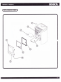
SPIRIT 550
Wood Stove
Installation and Operating Instructions
Save These Instructions
Please read this entire manual before vou install and use your BOSCA SPIRIT 550 Wood Stove.
Failure to follow instructions may result in property damage, bodily injury, or even death.
TABLE OF CONTENTS
SAFETY NOTICES
INTRODTJCTION
INSTALLATION
3
The floor
Installation clearances
Chlmne-v
Connectlon
6
6
CHIMNF.Y
Factory Built
Chimney
7
Masonry Chimney
Masonry Fireplace
Chimney Heieht
Combustible Wall Chimnev Conneclor Pass - Throushs
MOBILE HOME INSTALLATION
OPERATING AND LIGHTING INSTRUCTIONS
Lishtins
l0
11
l1
t2
72
MAINTENANCF
Baffle
L2
Disoosal of Ashes
13
Glass Replacement
13
Glass Cleanins
13
Doors Gasket Replacement
l4
Refractory Brick Replacement
L4
t5
Crcnsnte - Fnrmafinn and necd for rcmnwel
15
TROUBLESHOOTING
16
RF',PT.ACFMF'NT PARTS
t6
IIFETIME LIMITED
WARRANTY
18
.
SAFETY NOTICES
I
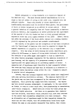
When your BOSCA SPIRIT 550
is
not properly installed, a house fire may result. To reduce the risk of fire, follow the installation
instruciions. Contact local building, fire officials, or authority having jurisdiction about restrictions, permit and installation
inspection requirements in your area.
-
DO NOT USE CHEMICATS OR FTUIDS TO
START THE FIRE.
DO NOT BURN GARBAGE OR FLAMMABLE FLUIDS SUCH
AS
GASOLINE, NAPHTHA OR ENGINE OIt.
HOT WHITE IN OPERATION. KEEP CHILDREN, CTOTHING AND
FURNITURE AWAY. CONTACT MAY CAUSE SKIN BURNS.
NEVER USE GASOLINE, GASOTINE-TYPELANTERN FUEL,
KEROSENE, CHARCOAL TIGHTER FLUID, ON SIMITAR TIQUIDS TO
START OF "FRESHEN UP" A FIRE IN THIS STOVE, KEEP Att SUCH
TIQUIDS WEIL AWAY FROM THE STOVE WHITE IT IS IN USE.
DO NOT ELEVATE FIRE, BUILD WOOD
FIRE DIRECTTY
ON FIREBOX
HEARTH.
BURN NATURAT WOOD ONIY. DO NOT BURN ANY OTHER
WOOD, ADEQUATETY AIR-DRIED.
AVOID BURNING GREEN WOOD.
FUELS. PREFER HIGH-QUAUTY
WOOD A SAFE DISTANCE FROM THE STOVE AND KEEP IT
OUT OF THE SPACE AROUND THE STOVE ORAREAS REQUIERED
FOR REFUETING AND ASH REMOVAL
KEEP
THE BOSCA SPIRIT 55O IS APPROVED FOR MOBITE HOME
INSTALTATION. PTEASE FOLTOW THIS MANUAT CAREFUTLY
FOR ANY INSTAIIATION, INCLUDING IN A MOBITE HOME.
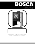
INTRODUCTION
We would like to congratulate you for selecting our BOSCA SPIRIT 550. By purchasing a BOSCA product, you receive the
advantage of the strength, guarantee and the more than 20 years experience BOSCA has in producing stoves and heaters
equipped with secondary air combustion system, which enable efficient consumption of the wood, as well as minimum
impact to the general environment.
Bosca Chile S.A. is the leading company in the production of wood stoves in Chile, with more than 250,000 stoves sold and
there are Bosca products installed in houses in Spain, Portugal, fugentina, Uruguay, Ecuador, and Mexico. ln the production
of our stoves, we use only the finest materials. This, along with the experience of the members of our staff, means for you a
product of high quality and dependability.
The BOSCA SPIRIT 550 is a clean burning EPA certified, non-catalytic wood buming stove with 3,6 grams per hour particulate.
The BOSCA SPIRIT 550 has been tested and listed by OMNI-Test Laboratories, Inc. The test standards are U[1482 and ULC
s627.
Please read this entire manual before you install and use your BOSCA SPIRIT 550. The purpose of this manual is to familiarize
you with your SPIRIT 550's safe installation, operation and maintenance. It contains information that will be useful, so save
it
for future reference.
INSTALLATION
For your ultimate safety and the proper function of your stove, it should be installed in accordance with the instructions of
this Manual.
The first step is to decide where is the most appropriate place to install your stove.
It is important to install the stove in an area with adequate air circulation and flow. This allows the warm air to more easily
reach the intended rooms. Additionally, your stove's placement should enable, and not be an obstacle to, free movement
of people, especially children.
Your stove and chimney connector must be far enough from combustible materials to meet all clearance requirements.
The floor
One of the main necessary precautions when instaltng a wood stove is to leave sufficient space between the stove (top, sides,
back, front, and under stove pipes) and any other material that can catch fire.
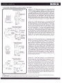
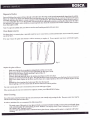
If the stove is to be installed on a combustible floor, it must be placed on an approved l/2" (13mm) non-combustible hearth
pad with k = 0.84 BTU/in ftz
In the USA, the floor protecior must extenil-8" beyond each side of the flue loading door
and 16" to the front. In Canada, the floor protector mu st extend 8" (200mm) beyond-each side and the back of the appliance
and 18" (450mm) to the front. (See fig. 1)
lq'!.
8" (200
Canada
8".
Fig.
I
of 2" (50mm) beyond either
a rear vent installation the floor protection must also extend under the stovepipe a minimum
side of the pipe.
How to determine if alternate floor protection materials are acceptable.
All floor orotection must be non-combustible (i.e., metals, brick, stone, mineral fiber boards, etc.). Any organic.materials-(i'e',
io-n"ititjte and must not be used. The floor protection specifted includes some form
;i;.i
as n-uatue (thermal resistance) or k-factor (thermal conductivity)'
ilil;. ,i,ffi;;;;;;;J";;,
5i til;;fJ;i!;'"ti"'";r.t
-"
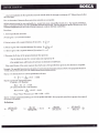
Procedure:
1.
Convert specification to R-value:
i. R-value given - no conversion needed.
ii.
k-factor is given with a required thickness (T) in inches: n
inches: n
=f
x
f
=nfu
iii. K-factor is given
with
a required thickness (T) in
iv. r-factor is given
with
a required thickness (T) in inches: R = r x T
x
f
2. Determine the R-value of the proposed alternate floor protector.
i. Use the formula in step (1) to convert values not expressed as "R"'
ii.
For multiple layers, add R-values of each layer to determine overall R-value.
is acceptable.
If the overall R-value of the system is greater than the R-value of the specified floor protector, the alternate
Examnle: The snecified floor protector should be 3/4-inch thick material with
a;;n.iit with an i-factor of 0.2bver 1/8" mineral board with a k-factor of 0.29.
a k-factor of 0.84. The proposed alternate is
Step (a): Use formula above to convert specification to R-value.
R=
*"t=#nxo.75
=0.8e3
R of proposed system.
Step
' (b): 4"Calculate
brick of r = 0.2, therefore:
Rbrict<=O'2x4=0.431
1/8" mineral board of k = 0.29, therefore
Rmineratboard
0.125 = 0.431
= #g
"
Rtotal = Rbrick+ Rmineral board=
0'8 + 0'431 =
l'23I
required,
Step (c): Compare proposed system Rtotal of 1.231 to specified R of 0.893. Since proposed system Rtotal is greater than
is
the system acceptable,
Definitions
D
l\-
_
(ftz) (hr) ('F)
Btu
k=
(in) = Kxt2
(frz) (hr)
gru)
..
t\-
(Btu) (ft)
(ftz) (hr) ("F)
fF)
-
r-
(ftz) (hr) fF)
(Btu) (in)
_1
k
Installation Clearances
It is extremely important that you respect required installation distances and that you respect local installation regulations.
This is for your safety! The manufacturer is not responsible for the product, if it is not installed following these recommendations.
These clearances may only be reduced by means approved by the regulatory authority.
A combustible surface is anything that can burn (i.e. sheet rock, wallpaper, wood, fabrics etc.) These surfaces are not limited
to those that are visible and also include materials that are behind non-combustible materials. If you are not sure of the
combustible nature of a material, consult your local fire officials.
Parallel Installation
CTEAMNCE REQUIREMENTS:
A.. SIDEWATLTO UNIT
B.- BACKWALL TO UNIT
C.. CORNERWALLTO UNN
D.. SIDEWALT TO CONNECTOR
E.- BACKWALT TO CONNECTOR
F.- CORNERWALTTOCONNECTOR
G.. UNITTO CEILING
H.. FTOOR TO CEITING
Corner Installation
STANDARD RESIDENTIAT INSTATTATION
(SINGIEWALL & DOUBTEWATL CONNECTOR):
13"
20'
t4'
22.
22,5
2t',
49'
84"
(330 mm)
(sos mmJ
(356 mm)
(559 mm)
(572 mm)
(533 mm)
0.247 mm\
(z.tg+ mmi
Note: Double wall is only allowed in US installations
7'
(178 mm)
15,5" (394 mm)
11" (279 mm)
16" (406 mm)
17" (432 mm)
18" (457 mm)
49" (1.247mm)
84- (2.134 mm)
ATCOVE INSTALIAT]ON
WITH (DOUBLE WALL CONNECTOR):
7'
11"
16'
17.
18"
49"
84'
15,5'
(178 mm)
(394 mm)
(279 mm)
(406 mm)
(432 mm)
(457 mm)
(1.247mm)
(2.134 mm)
'himney Connection
The chimney connector is a single walled pipe used to connect_ the stove ^to^ lhe chimney.-For use with the appliance the
;ilt-;;;';;irn*i"iMUST be 6ein diamet'er, with a minimum thickness of.24 gauge black steel or 26 gauge blued steel.
and galvanized steel pipe is rot acceptable for use with the applipnce. These materials cannot withstand the
extfeme temperaTures of a wood firil and can give off toxic fumes when heated.
41rr-inir*
Do not use the connector pipe
as a chimney.
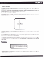
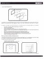
Each chimney connector or stovepipe section must be installed to the stove flue collar and to each other with the male
(crimped) end toward the stove. See fig 2.
1
"i'n
TOWARDS
1
FIUE GAS
DIRECTION
I
Fig.2
This prevents any amount of condensed or liquid creosote from running down the outside of the pipe or the stovetgp' All
the sections do not
1oitttril".t"aingihe flue collar connection musi be secured with three sh-eet metal screws to ensure that
separate.
For the best performance the chimney connector should be as short and direct as possible, with no more than two 90 elbows.
horizontal run is 36" and a recommended total length of stovepife should not exceed 10 feet. Always slope
horizontal runs upward 1/s" pet foot toward the chimney.
ifr" -i"i-"in
No part of the chimney connector may pass through an attic or roof space, closelor other concealed space, or through a
fiooiceiting. All sections'of the chimney"connectors rilust be accessible fo-i cle_aning. Whelg-n_q1sgg"-'!lt9ugh.? wallorpartition
of combus1ble construction is desired, the installation must conform with NFPA flI or CAN/CSA-B365, and is also addressed
in this manual.
CHIMNEY
DO NOT CONNECT THIS UNIT TO A CHIMNEY
FLUE SERVING ANOTHER APPLIANCE. DO NOT
CONNECTTO ANY AIR DISTRIBUTION DUCT OR
SYSTEM.
{his
room heater must be connected to a 6" factory built U[ 103 HT chimney (UtC 5629, in Canada) or a code-approved
.asonry chimney with a flue liner.
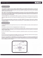
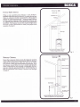
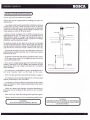
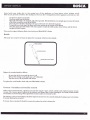
Factory Built Chimney
When a metal prefabricated chimney is used, BOSCA's
irstallation instructibns must be followed. Ydu must also purchase
(from an authorized retailer) and install the ceiling support
package or wall pass-through and "T" section package, firestops
(where needed), insulation shield, roof flashing, chimney cap,
etc. Maintain proper clearance to the structure as recommended
bv BOSCA. The'chimney must be the required height above
tfie roof or other obstructions for safety and proper draft
operation. (See fig.3)
Sunoort Box
wiflf built - in
starter section
One storv house installation with attic
Chimdey is supported by celling
Fig.3
Masonry Chimney
Adjustable roof
Ensure that a masonry chimney meets the minimum standards
of the National Fire Piotection Association (NFPA) by having it
inspected by a professional. Make sure there are no cracks,
loose mortaror other signs of deterioration and blockage. Have
the chimne.y cleaned before the stove is installed and operated.
When conirecting the stove through a combustible wall to a
masonry chimneV, special methodls are needed (See fig. 4).
Refer to-Combustible-Wall Chimney Connector Pass-Throughs
Flashing
Chimney Sections
Chase Enclosure
on page 9.
Wall Strap
WallThimble
Tee Support
Bracket
Tee Clean - Out
Access
Chimney through outer wall with enclosed chase
Chimney h supported by tee support bracket
Door
Iasonry Fireplace
There are listed kits available to connect a stove to a masonry
fireplace. The kit is an adapter that is installed at the location of
the fireplace damper. The existing damper may have to be
removed to allow installation. (See fig.5)
Chimney through outer wall wilh enclosed chase
Chimirey is supported by tee suppon bracket
Fig.5
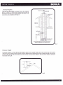
Chimney Height
A masonry chimney or a ljsted factory-build chimney must be the required height above the roof and any other nearby
obstructiohs. The chimney must be ai least 3' (90 cni) higher than thehighest pbint where it passes through the roof and
at least 2' (60 cm) higher than the highest part of the roofor structure that is within l0' (305 cm) of the chimney, measured
horizontally (See fig. 6).
Fig.6
Combustible Wall Chimney Connector Pass - Throughs
Method A.12" (304.8 mm) Clearance to Combustible Wall
Member: Using a minimum thickness 3.5" (89 mm) brick and
a 5/8" (15.9 mm) minimum wall thickness clay liner, construct
a wall pass{hrough. The clay liner must conforin to ASTM C3l5
(Standard Specification for Clay Fire linings) or its equivalent.
Keep a minimum of 12" (304.8 mm) of brick masonry between
the clay liner and wall combustibles. The clay liner shallrun
Minimum chimenev clearance lo bricl
and combustibles Z in. (50.8 mm)
Llll
|ffi-]|
F#1t
from the brick masonry outer surface to the inner surface of the
chimney flue liner buinot past the inner surface. Firmly grout
or cement the clay liner in place to the chimney flue liner.
2
iffiil
tl_q}+lil
Tlffili
o
.E
t
lffii
O
Minimum l2 in. (304.8 mm)
to combusiibles
length
Nonsoluble
refractory cement
Minimum clearance
9 in. (228.6 mm)
-
Chimnev
Conneclor
Chimnev
\I
lensht flui;h
I
wilfr inside
- --1 ^
offlrre
Air SDace
I in. (228.6 mm)
Use chimnev
mfrr-parts
t<i
attach connector
securely
Method B. 9" (228.6 mm) Clearance to Combustible Wall
Member: Using a 6" (152.4 mm) inside diameter,listed, factorybuilt Solid-Pak chimney section with insulation of 1" (25.4 mm)
or more, build a wallpass{hrough with a minimum 9" (228.6
mm) air space between the outer wall of the chimney length
and wall combustibles. Use sheet metal supports fastened
securely to wall surfaces on all sides, to maintain the 9" (228.6
mm) air space. When fastening supports to chimney length,
do not penetrate the chimney liner (the inside wall of the SolidPak chimney). The inner end of the Solid-Pak chimney section
shall be flush with the inside of the masonry chimney flue, and
sealed with a non-water soluble refractory cement. Use this
cement to also seal to the brick masonry penetration,
Method C. 6" (L52.4 mm) Clearance to Combustible Wall
Member: Starting with a minimum 24 gage (.024" [.61 mm])
6" (152.4 mm) metal chimney connector, and a minimum24
Sheet steel
supports
Minimum chimenev clearance to
sheet steel suoborts and
combustibles 2 iri. (50.8 mm)
Two air channels
each 1in. (25.4mm)
Chimney
connectot
gage ventilated wall thimble which has two air channels of 1"
(25.4 mm) each, construct a wall pass{hrough. There shall be
a minimum 6" (152.4) mm separation area containing fiberglass
insulation, from the outer surface of the wall thimble to wall
combustibles. Support the wall thimble, and cover its opening
with a 24-gage minimum sheet metalsupport. Maintain the 6"
(152.4 mm)space. There should also be a support sized to fit
and hold the metal chimney connector. See that the supports
are fastened securely to wall surfaces on all sides. Make sure
fasteners used to secure the metal chimney connector do not
penetrate chimney flue liner.
Masorw
Chimney
Minimum chimenev clearance to
sheet steel suo'Dorts and
combustibles 2 in (50.8 mn)
Minimum clearance
I in. (25.4 mm)
Method D. 2" (50.8 mm) Clearance to Combustible Wall
Member:
Start
with
a solid-pak listed factory built chimney section
at least 12" (304 mm)long, with insulation of 1" (25.4 mm) or
more, and an inside diameter of 8" (2 inches [51 mm] larger
than the 6" [152.4 mm] chimney connector), Use this as a pass-
through for a minimum Z4-gage single wall steel chimney
connector. Keep solid-pak section concentric with and spaced
Chimney
-
Air Soace
2 in. {5d.8 mm)
Masoruy
Chimne-v
l" (25.4 mm) off the chimney connector by way of sheet metal
support plates at both ends of chimney section. Cover opening
with and support chimney section on both sides with 24 gage
minimum sheet metal supports. See that the supports are fastened
securely to wall surfaces on all sides. Make sure fasteners used
to secure chimney flue liner.
NOTES:
1. Connectors to a masotry chimney, excepting method B, shall extend in one continuous section through the wall pass{hrough system and the chimney wall, to but not past
the inner flue liner face2. A chimney connector shall not pass through an attic or rool space, closet or similar concealed space, or a floor, or ceiling.
MOBILE HOME INSTALLATION
I
For use only in USA (not allowed in Canada).
Follow these special requirements for installing your stove in a
mobile home:
-
An outside air inlet must be provided for combustion and must
remain clear of leaves, debris ice and/or snow. It must be
unrestricted while unit is in use to prevent room air starvation
Spark Arestor Cap
which can cause smoke spillage and an inability to maintain a fire.
Smoke spillage can also set off smoke alarms.
Strom Collar
- Outside air inlet installation: Use a BOSCA connector (see
Replacement Parts, pg. 16) which you can purchase from an
official BOSCA dealer, a 4" single wall aluminum flex pipe of
appropriate length for installation, a rain cap and two 4" clamps,
Roof Flashing
available at your local hardware retailer.
To install the outside air inlet, place the connector over through
Joist Shield
/
Firestop
Double wall
connector pipe
the hole behind the heater, connect the flex pipe and attach it
securely with one of the two clamps. The other side of the flex
pipe should be connected on the outside to the rain cap.
-
Permanently attach the stove to your mobile home's floor. The
pedestal must be bolted to the floor. Use /a" holes in the base to
bolt down the stove.
-
Regulation requires that unit must be grounded. Attach a piece
oooooo
f # o8 cooper wire, at least 18" in length from the stove to the
,rassis of the mobile home.
-
Stove must be installed with an approved Ut103 HT ventilated
chimney connector, ULl03 HT chimney and terminalcap with
spark arrestor. Never use a single wall connector in a mobile
home installation.
Floor Protector
-
Outside Air
RearVent
-
- See clearances to combustibles on page 5 of this Manual or in
the Serial Number Label on the back of the stove.
-
Follow the floor protections requirements detailed o n page 3.
In Canada, this stove must be connected to a 6" factory-built
chimney conforming to CAN/UIC-629M.
-
Use slicone to create an effective vapor barrier at the location
where the chimney or other components penetrates to the exterior
of the structure.
- Follow the chimney and chimney connector manufacturer's
instructions when installing the flue system for use in mobile
homes.
-
Burn wood only. Other fuels may generate poisonous gases.
Chimney must be removed when transporting mobile home.
CAUTION:
WARNING:
DO NOT INSTALL IN SLEEPING ROOM
THE STRUCTURAL INTEGRITY OF THE MOBILE
HOME FLOOR, WALL AND CEILING/ROOF MUST
BE MAINTAINED,
OPERATING AND LIGHTING INSTRUCTIONS
Your SPIRIT 550's performance depends largely on how it is operated. Please read this section carefully before lighting your
first fire.
When you lieht your first fire, the stove will emit some smoke and the smell of paint. This is normal. Open the windows to
vent th6
rooir and eliminate the
smell
.
Before lighting your stove, ensure that the baffle is correctly installed. For baffle installation instructions, see page 12
(Maintenance).
Before lighting your stove, ensure that the refractory bricks are conectly installed. For refractory bricks installation instructions,
see page 14 fMaintenance).
Iighting
I
I
I
I
I
I
!
u
Place crushed sheets of paper or firelighters in the center of the firebox.
Place some kindling
on top of the paper and some small split logs, preferably in a vertical position.
Light the fire and close the door.
Open the door of the ashtray and leave it this way for approximately 3 minutes or until the split logs are alight.
Add the load of firewood, placing the lightest logs directly over the fire and the heavier ones on top of these.
Close the door of the firebox and maintain the door of the ashtray open for approximately 5 more minutes.
Once the logs are alight, close the door and place the Air Control on HIGH lor 20 minutes.
When the stove reaches the operation temperature and there is sufficient draft, graduate the Air Control to the
desired position. It is recommeirdable to slofr'ly adjust this command before graduating to the MEDIUM position
(prolonfed combustion).
You will find by experience how to best manage your stove to your liking. You must not expect an immediate reaction
from the nre r.,ineri moving the Air Control. ThE flame will not intensify n6r extinguish quickly as it would with liquid
or gas fuels. Solid fuels,like firewood, react slowly.
If the fire is initiated as instructed, a good base is established for an effective combustion that is smokeless and that
does not pollute.
WARNING
DO NOT OVERFIRE.IF THE STOVETOP OR
CHIMNEY CONNECTOR PIPE GLOW RED,
YOU ARE OVERFIRING.
IMPORTANT
DO NOT OPERATE THE STOVE FOR
PROLONGED PERIODS WITH THE DOOR OF
THE ASHTRAY OPEN. DO SO ONLY UNTIL THE
WOOD LOAD IS ALIGHT.
To obtain good combustion during the whole night, proceed as follows:
U
!
U
Form a base of live coals at the bottom of the firebox.
Load the stove completely with dry firewood.
When flames begin to appear on the logs move the Air Control to MEDIUM.
How do I load my stove after a prolonged combustion?
!
I
!
U
At the end of a long combustion cycle, reestablish the fire adding a few small split logs and small
logs.
Open the door of the ashtray for 5 minutes or until the split logs and small logs are alight.
logs.
Allow the temperature of the stove to recuperate before adding larger
Reload the stove according to the description above.
MAINTENANCE
The SPIRIT 550 requires little maintenance. However, there are parts of your stove that should be checked periodically,
Baffle
Your SPIRIT 550 stove has a removeable baffle that needs to be replaced periodically, depending on the stove's use.
When the baffle needs to be removed, make sure that the stove is cold before putting your hands into the firebox.
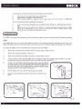
To replace the baflle, you have to dismantle the rear panel of your stove (fig.7):
1)
\
3)
4l
5)
Release the 4 bolts located on the sides of the rear panel, using a 10mm wrench.
Remove the rear panel, pulling it towards you.
Release the bolts that fix the baffle to the firebox, using a 10mm wrench.
Once the bolts are loose, slide the baflle down as indicated in figure 8. Carefully, angle the baffle on one side
to make sure it doesn't accidentally fall, as this may result in serious injury (fig. 9)
To place the new baffle in its proper position, insert it into the firebox,
in such a way that it rests on the support brackets installed specially for
the baffle. Make sure that the baflle air pipe is inserted completel.y into
the hole in the back of the firebox (Fig 10) and the bolts have gone
through the holes to the outside of the fixebox.
6)
7)
Bolt the baffle to the rear wall of the firebox from the outside.
Place the rear panel back in place, be sure that it is correctly set and
bolt it.
Fig
Disposal of Ashes
into the ashbin'
your unit,s firebox has a grooved base, through which the ashes from the wood bumed automaticallv denosit
hot for up to
iemain
coals
ian
.oii
ur"
ii"",i"-il1lt;tth"
-ine
when rhe ashbin is full,irake sure that the stove ind the ashes
be placed
should
ashes
of
itoseo,container
ntti"g'riai
36 hours) and place tn" uiiiu, i" u metal containlr *rttt tigrrt
If the ashes
disposal'
final
materials,.pendins
co#bustibie
all
rrofi-t
on a noncombustible tloor or on the grourro,'iu"tt-u*iv
in itie cl.,te? container until all cinders
are disoosed of bv buriat in soil or otherwise bJfi',il;"",eX'iir;y;;;lJ6;;min"c
have droroughly tooled.
i
with your stove'
Note: To open the ashbin door, you have to use the steel handle provided
Glass Replacements
and should therefore not be marred by normal
The front glass is a ceramic glass, especially made for use in wood stoves,
use of the stove.
Never operate your stove with broken glass'
If for any reason the glass does break, it will be necessary to replace it.
m1
lIll
ilil
!-il
U
Fig.
1l
Replace the glass as follows:
Make sure that the fire is completely extinguished and the stove is cold.
hinds with eloves thal are a[propriate for this t}pe of work'
R"-oud the front door, c-arefully pushing it upward (l'ig I l)'
i;;;.;;;";
Place the door on a flat surface.
-ti;;;r;;
tfr" nottr that hold down the stainless-steelframe on the stove door.
door, once the frame has been removed'
Seoarate the door rru-" ito- trr;;lass. ih" ths rn""ia ne loose on the
i6 originalposition, then screw the frame in place on the
ii#';;#r;;;;ruIil
o" ir.t" 3oor, resetTiieHilt"
door.
n"l"itu1 the door, inserting the bottom part
ii;i;;;ldhd''g
i.t"*
first, then the top part'
fire,"ensure that the door is seated in its correct position.
of glass.
Use only ceramic glass for use in wood stoves. Do not use other type
If the ceramic glass of your stove needs to be replaced, contact your official
BoscA Dealer'
Glass Cleaning
one of the more attractive features of your stove
obscured when the glass becomes dirty.
is that you can actual$ enjoy seeing the
fre'
However, your view may be
In order to minimize this, we recommend the following advice:
-
content of the wood used, along
The main cause of dirt spots on your glass is direc-tly connected with the humidity
Store it adequately, and keep the
wood.
dry
only
ur"
Aiiaoniroisettifif;""i;ilFrtitiotr.
with maintai"idih"
Air Control at the "Medium" position'
p'"ri;i;;ilt viiitr u io*-ercial stove glass cleaner, waiting untilthe glass is completely cold before
clean the glass
cleaning.
Joors Gasket Replacement
STAINTESS STEET FRAME
Your SPIRIT 550 uses rope-type fiberglass gaskets at the interior of the front and ashtray doors to sealed it. After a time of use,
gaskets can becomg brlltle anii compressed, begin
To
to lose their effectiveness and need to be
replace.
replace any gasket, be sure that the fire is out and the stove is cold and follow as is describe:
Use Fil-Tec'M MD .500 G Black Fiberglass Rope or equivalent.
Remove the existing gasket.
Clean the stainless steel channel.
Measure the length of the rope by lalng it out in the stainless steel channel.
Remove the rope from the channel and cut it to the appropriate length. Take care to ensure that the rope does not
unravel.
Place a bead of high-temperature adhesive in the clean stainless-steel channel.
Beginning at one of the ends, press the gasket into the stainless-steel channel interior.
Befbre cutting, make sure the rope ends properly meet. Do not overlap rope ends.
Firmly press the rope en make sure it properly seats into the stainless-steel channel interior.
Clean any excess adhesive and allow to dry.
Refractory Bricks Installing and Replacement
Your SPIRIT 550's firebox interior is covered with 18 refractory bricks (figure 13 a.). To avoid damages in your stove during
the transport , the refractory bricks are not installed and are stored in a box inside your stove firebox.
To install the refractory bricks, proceed as follow:
-
Use gloves to protecl your hands
Installthe refractory bricks as shown in figure 13 b.
,\
'd\
\/
'\'\
..?)
-"./'
./?
o!!/'
+2
fig. 13 a.
fig. 13 b.
Some bricks may brake due to the normal use of the appliance or from impact when loading wood.
lf this occurs, proceed as follows, after making sure that any fire ils extinguished and the'appliance and brick-are cold:
-
Use gloves to protect your hands
Clean any ashes from the firebox
Take hold of the brick to be repla-ced, and push it upwards. This should leave you enough space to move the bottom
of the brick toward the center of the frebbx
any- pieces of brick remaining in the space where the new brick will be placed
To insert the new brick, place the upper end in the molding in the top part of ihe firebox
Once the upper part of the brick is well seated, push it tow-ards the insiile surface of the firebox, until the brick
completely seated in place.
9l"qn
is
If you need to replace Refractory Bricks, check with your OfficialBOSCA Dealer.
Handle
After some use, it may be necessary to replace the wood part of the front door handle.
ha
\)
,
STEET
HANDTE
Replace the wooden handle as follows:
-
Be sure that the lire is out and the stove is cold
Remove the existin-g wood handle (use a N'4 Allan key)
Turn the screw as far as possible and remove
To replace the wood handle, check with your OfficialBOSCA Dealer.
Creosote - Formation and need for removal
When wood is burned slowly, it produces.tar and other organic vapors, which combine with expelled moisture to form
creosote. The creosote vapors condense in the relatively cool chimney flue of a slow burning fire. As
accumulates on the flue lining. When ignited this creoiote makes an extremely hot fre.
i
result, creosote residue
The chimney connector and chimney should be inspected at least every two months during the heating season to determine
if creosote build up has occurred.
If creosote has accumulated it should be removed to reduce the risk of a chimney fre.
Your SPIRIT 550 will operate with few problems, and most of those will occur due to inconect operation, poor-quality wood,
improper installation, or failure to clean the flue piping.
The following lists solutions to the most common problems in the operation of the SPIRIT 550:
Solution
-Use seasoned wood
-Reload your stove when it has a good bed of embers
- Set
the Air Controlin "M6dium" or "High" position.
-Use seasoned wood
normal for your stove to emit smoke during the first
few minutes of operation. The smoke will dissipate when
the hrebox reaches the normal operating temperature..
- It is
- Use seasoned wood
- Keep the Air Controlat "Medium" or "High" position
- Make sure that the gasket is in good condition.
-
lf your heater is more than 2 years old, replace the baffle.-
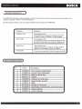
REPLACEMENT PARTS
N"
Code
I
2
3
t2720064
r2720078
to3to274
6
10320127
12720069
12720070
7
t2720071
8
9
10
10310320
10310209
12720073
12720072
4
5
l1
Description
Door (without ceramic slass)
Ceramic Glass (with sasket)
Refractorv Bricks (set)
Ashpan
Ashpan Door (with rooe)
Wood Handle Assemblv
Baffle
Outside Air Connector
Glass Retainer (with brackets. screws and rone)
Damoer Handle
Owner's Manual
I
REPLACEMENT PARTS
I
Yooo
'ooo
DO NOT REMOVE THIS LABEL / NE PAS ENLEVER CETTE ETIQUETTE
BOSCfi
CONTACT LOCAL BUILDING OR FIRE OFFICIALS ABOUT INSTAI-LATION AND RESTRICTIONS IN YOURAREA / REINSEIGNEZ.
VOUS AUPRES DES AUTORITES LOCALES DE LACOI'ISTRUCTION ET DE LA PREVENTION DES INCENDIES AU SUJET DES
RESTRICTIONS ET INSPECTIONS D1NSTALLATION OANS VOTRE REGION.
oxtlid
l.hor.loti6,
ln
c,
LISTED SOLID FUEL BURNING APPLIANCE SUITABLE FOR USE IN RESIDENTIAI- II{STALLATIONS. /APPAREIL DE CHAUFFAGE A
COMBUSNBLES SOLIDES HOilOLOGUE POUR INSTALLATIONS RESIDENTIETLES.
MoDEL/ MoDELE,
TESTED T0 / TESTE AUX NORMES: UL 1482, ULC-S627
Room Heater, Solid Fuel Type. For use in mobile homes only in US.
oe a Combustibles Solides. Pour usaoe dans les maisons mobiles
SplRlT 550
PREVENT HOUSE FIRES - lnstall and use only in accordence with the manufacturer's
your local buildinq
installation and oDeratin0
building or fire offtcials
operating instructions. Contact vour
about restrictions and inatallation inspection in your area. Refer to local building
precautions required
passing a
reouired for oassino
codes and manufacturer's instructions for orecautions
ceilinq. Do not run a chimney
chimnev connector
chimney trough
trouqh a combustible wall ceiling.
trough a combustible wall ceiling. Do not connect this unit to a chimney flue
serving another appliance. Clearances may be reduced by methods specified in
NFPA 21'1, listed wall shields, pipe shields, or other means approved by local
building or tire officials.
PREVENTIoN DES INCENDIES: lnstallez et utilisez conform6ment aux instructions du fabricant.
Renseiqnez.vuos auDris des autoritis locales de la construction et de la Dr6vention des incendies au
suiet d6 restrictioni et insoections d'installation dans votre r6oion. De:s m6thodes sD6ciales sont
reduises lors du oercaoe d'un mur ou Dlafond. V6rifier les instrictions du fabricant et'les codes du
baiiment. Ne oas lairi o-asser le tuvau de chemmin6e directament a favers une surface combustible.
Ne oas connbcter cet aooareil
li chemin6e d'un autre aooareil. Les d6oaoements minimaux des
i
mahides sp&ifieei dans NFPA 211, avec des
Drotections murales horioloou6es. des orotections de chimen6e hbmoloou6es. ou d'autres movens
mat'6riaux combus{iblesb'euvent etre r6duits selons les
ipprouv6s par les autoiit6s'de
Fait$ foncfionner l'appareil
with feed door closed - open to
feed fire only.
construction et de la pr6-ventiirn des incendies.
avec les portes de chargement ferm6es . ouvrir uniquement pour charger.
Ne pas utiliser une grille supplSmentaire pour 6lever le feu . faites le feu directement sur le foyer.
Do not use a grate to elevate fire - build fire directly on hearth.
Ne pas faire fonctonnier l?appareil avec la porte ceodrier ouverte.
Do not operate with the ash door open.
DO NOT OVERFIRE - lf heater or chimney connectors glows, you are overfiring.
buildup may occur
li
Pour usage uniquement avec du bois.
For use with solid wood fuel only (cord wood).
Operated
Serial Number
Numero de Serie
rapidly.
NE PAS SURCHAUFFER - Si une partie de l'appareil ou du reccordement de chemin6e commence
rougeoyer, vous etes en situation de surchauffe:
i
goudron puet se produire rapidement.
FREESTANDING / INSTALLATION
MSG vers une chemin6e pr6fabriqu6e homologu0e (type UL103 HT ou ULC 5629) ou vers une chemin6e maconn6e.
CLEARANCE REQUIREMENTS:
DEGAGEMENTS MINIMAUX DES MATERAUX CoMBUSTIBLES:
STANDARD RESIDENTIAL INSTALLATION
(SINGLEWALL & DOUBLEWALL CONNECTOR):
INSTALLATION RESIDENTIELLE STANDARD
ITI.IYAIJ DE RACCORDEMENT A SIMPLE PAROI ET A DOIIBLE PAROII:
Sinqlewall
4..
8..
c.,
0..
E..
F..
G.H..
SIDEWALL TO UNIT / DU MUR DE COTE AU POELE
BACKWALL TO UNIT / DU MUR ARRIERE AU POELE
CORNERWALL TO UNIT I DU MUR DU COIN AU POELE
SIOEWALL TO CONNECTOR I OU MUR DE COTE AU RECCORD DE CHEMINEE
BACKWALL TO CONNECTOR / DU MUR ARRIERE AU RECCORD DE CHEMINEE
CORNERWALL TO CONNECTOR I DU MUR DE COIN AU RECCORD DE CHEMINEI
UNIT TO CEILING I OU POELE AU PLAFOND
FLOOR TO CEILING I OU SOL AU PLAFOND
Foradditional type8 ol inslallations and clearancos consult your ownsB manual.
ALCOVE INSTALLATION
WITH (DOUBLE WALL CONNECTOR):
INSTALLATION DANS UN ALCOVE
fiUYAU DE RACCOROEMENT AU DOUBLE PAROII
Corner Doublewall
13" (330 mm)
ZO" (508 mm)
mm)
t4' (356
22" (559 mm)
22.5'$tzmmj
Zl' (533 mm)
49" (1.247 mm\
84' (2.134 mm)
7'.
15,5'
1l'
l6'
17"
18"
49'
84'
Doublewall
mm)
il78
'394
.178 mm)
7',
mm)
279 mm)
406 mml
432 mm)
457 mm)
18'
1.247mm)
49"
15,5"
394 mm)
279 mm)
1l'
l6'
406 mml
17"
2.134 mm)
432 mm)
457 mm)
l.247mm\
84'
2.134 mm)
Poqr d'autres modes d in€tallation etdogagem€nb suppl€mentaires oonsultezvotres manugl du proprigtaire
Note: Double wallis onlyallored in US insta
MINIMUM CLEARANCES TO COMBUSTIBLES:
DEGAGEMENTS MINIMAUX AUX MATERIAUX COMBUSIIBLES:
BAGKWALL / MUR
NON. COMBUSTIBLE FLOOR PROTECTOR
PROTECTEUR DE PLANCHER INCOMBUSTIBLE
ARRIERE ADJACENT WALL / MUR ADJACENT
FLOOR PROTECTOR MUST BE
*E[s]-ffi-l=;
I $S'l*.1E=
F=l.+l ;#:
|
CAUT l0
HAVING AN EQUAL OR BETTER INSULATING VALUE
(LoWER K VALUE) 0F kx.E4, lT MUST EXTEND
BENEATH HEATER, AND TO THE
FRONTISIDES'REAR
\'/ l''
N
LE PROTECIEUR
par:
DoT
TRE D.UI'IE
-g
+b
eo
;3
AE
6=
%', D'UN MATERIAL
L'APPAREN ET AU DEVAiIT. AUX COTES ET A
L'ARRIERE DE L'APPAREIL; COMME INIDIOUE.
CONSIDERABLE
DISTANCE AWAY FROM THE APPLIANCE.
DO NOT OVERFIRE - IF HEATER OR CHIMNEY GLOWS, YOU ARE
OVERFIRING.
Manufactured By: , Fabriqu6
DE PLANCHER
EPAISSEUR MINIMUM OE
: X3l,tilth:,ltf,%',fi iJ[?[
A
AS INDICATED.
INCOMBUSTIBLE AVANT UNE VALEUR DISOLANON
DE KX.84. IL DOIT S'ETEilDRE EN DESSOUS DE
CLOTHING AWAY. CONTACT MAY CAUSE SKIN BURNS. ^'*?
SEE
NAMEPLATE AND INSTRUCTIONS. KEEP FURNISHINGS AND
OTHER COMBUSTIBLE MATERIALS
A %' MINIMUM
THICKNESS, NON.COMBUSTIBLE MATERIAL
BOSCA CHILE
S.A.
ATT
ENT
I
0
Americo Vespucio Norte 2077 . Huechuraba - Santiago - Chile
U.S. ENVIROMENTAL PROTECTION AGENCY
Certified to comply with July 1990 particulate emission standards:
Certifi6 conforme aux normes EPA de julliet 1990 puor les 6missions de particules solides
N
: fi Efi H fl,:R
E
?i,' Y.i%'i ?'Jll;
CONTACT PEU CAUSER DES BRULURES A LA PEAU, GARDEZ
LES ENFANTS, LES VETEMENTS, LES MEUBLES, ET TOUS LES
MATERIAUX COMBUSTIBLES LOIN DE L'ESPACE DESIGNE DE
L'APPAREIL. LIRE ATTENTIVEMENT LES ETIQUETTES ET LES
INSTRUCTIONS. NE PAS SURCHAUFFER, SI L'APPAREIL OU LE
TUYAU DE CHEMINEE ROUGISSENT, VOUS SURCHAUFFEZ.
MADE IN CHILE I FABRIQUE AU CHILI
nnntrnn !trntrnnn nn
2005 2007 2008 Jan. Feb.
Mar
Apr. May June July Aug. Sep. Oct. Nov. Dec.
LIFETIME LIMITED WARRANTY
Statement of Policy:
BOSCA warrants its products from component failure and defects in material or workmanship per the terms of the waranty
supplied with the product. All dealers and distributors shall honor BOSCA's warranties, regardless of whether they sold and
installed the product or not.
Installation and startup procedures are considered to be normal required activities not associated with warranty service. Issues
such as air shutter adjustments or venting should be included in startup. Such procedures are nor covered by warranty.
Warranty Period:
The warranty period for consumers begins at date of occupancy (new construction) or date of installation (remodel).
Limited Lifetime Warranty:
BOSCA's limited lifetime warranty guarantees that the following components will work as designed for the first_ 5 years on
all Wood Stoves to the original purchaser. This warranty covers: firebox, firebox panels, panels and door assembly. Certain
restrictions and exclusion may apply.
One Year Warranty:
Under this wananty, BOSCA covers all exterior surface finishes against defects in material and workmanship, for part repair
or replacements ahd limited for the first year to the original purchaser. Certain restriction and exclusions may apply.
CONDITIONS
This warranty is non{ransferable and is made to the original retail purchaser only provided that the purchase was made
through an iuthorized dealer of BOSCA. It must be installed and operated at all times in accordance with the Installation
and Operating Instructions furnished with the product, as well as any applicable local and national codes. Any alteration,
willful abuse, accident, or misuse of the product shall nullify this warranty. This limited Lifetime Waranty does not extend to
or included surface finish on the appliance, door gasketing, glass gasketing, glass, firebricks. It does not cover installation or
operational-related problems such as overfiring, usb of conbsive driftwood, downdrafts or spillage caused by environmental
conditions, nearby trees, buildings, hilttops, mountains, inadequate venting or ventilation, excessive offsets, or negative air
pressures caused by mechanicals systems such as fumaces, fans, clothes dryers, etc. Any installation, construction, transportation,
or other related coits or expenses arising from defective part(s), repair, replacement, etc., will not be covered by this warranty,
nor will BOSCA assume responsibility for them. Further, BOSCA will not be responsible for any incidental, indirect, or
consequential damages, except as results in damage to the interior or exterior of the building in which this appliance is
installecl. This limited Lifetime Wananty does not apply to the venting components, hearth components or other accessories
used in conjunction with the installation of this product not manufactured by BOSCA.
This wananty is void if the stove has been over fired or operated in atmospheres contaminated by chlorine, fluorine, or other
damaging chemicals, the stove is subjected to prolonged periods of dampness or condensation, or there is any damage to
the stonebr other components due to water ofweather damage which is the result of, but not limited to, improper,chimney
or venting installation.-BoscA may, at its discretion, fully discharge all obligations with respect to this warranty by either
repairing-or replacing the unit, or refunding the wholesale price of the defective part(s).
The wananty extended by BOSCA described above covers only the stoves appliances sold in the United States and Canada,
and will be considered null or avoid if the Serial label is removed or altered.
The Dealer is not authorized to alter this warranty.
Wananty limitations may not apply in your area. This wananty gives you specific legal rights. You may also have other rights
which vary from state to state.
All other stove warranties, expressed or implied are excluded to the extent possible by law. In addition, consumers also may
have other rights under relevant State and Commonwealth Laws.
.
LIFETIME LIMITED WARRANTY
I
IMPORTANT INFORMATION
Model:
Style:
Serial Number:
Purchase Date:
Purchased From:
BOSCA CHILE S.A.
Av. Am6rico VesPucio 2077
Huechuraba
Santiago - Chile
Telephone : (56) 2 3288500
Fax: (56\ 2 624 189'
'
Made in Chile
www.boscastoves.com