1
OP'ERATING
INSTRUCTIONS
FOR
BB2-1A & BB4-1A
Pro-Finish® Basket Blasters
EMPIRE
ABRASIVE EQUIPMENT CORPORATION
2101 WEST CABOT BLVD., LANGHORNE, PA. 11l047-18Q3 USA
• (215) 752-8800
• TELEX 831·378
• FAX (215) 752·9373
• EASY LINK62954372
CONTENTS
1.0
2.0
3.0
4.0
5.0
PAGE
Installation .................................................................................... 3
1.1 Dust Collector ................................................................. 3
1.2 Cabinet ........................................................................... 3
1.3 Electrical Connections .................................................... 3
1.4 Compressed Air Supply .................................................. 4
Operation ...................................................................................... 4
2.1 Selection of Media .......................................................... 4
2.2 Use of Harsh Media ........................................................ 5
2.3 Media Loading ................................................................ 5
2.4 Equipment Start-Up ........................................................ 5
2.5 Equipment Shut Down .................................................... 5
2.6 Equipment Adjustments ................................................. 5
Maintenance ................................................................................. 6
3.1 Daily Maintenance .......................................................... 6
3.2 Weekly Maintenance ...................................................... 6
3.3 Other Maintenance ......................................................... 6
3.4 Storage or Temporary Non-use ...................................... 7
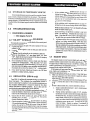
Troubleshooting ............................................................................ 7
4.1 Diagnosis and Remedy ............................................... 8-9
4.2 "On-Off" Interlock Solenoid ............................................. 7
4.3 Oscillation (884-1 A only) ............................................... 7
4.4 Basket Drive ................................................................... 7
Drawings .................................................................................... 10
5.1 Replacement parts BB4·1A .......................................... 10
5.2 Replacement parts 882-1A .......................................... 11
5.3 Electricals- BB2-1A and BB4-1A ................................. 12
5.4 Pneumatics- 884-1 A only ........................................... 13
5.5 MH-2 Short Handle ...................................................... 14
PRO·FINISHc~
BASKET BI.ASIERS ·
INTRODUCTION
This booklet has been designed to assist you·in the proper
installation, operation and maintenance of your new Empire
Pro-Finish System.
Read this booklet carefully and keep it handy for future
reference. If at any time, you have any questions or problems
regarding the operation and maintenance of your equipment,
contact your Empire Distributor, who is best qualified to assist
you with trained service technicians, replacment parts and tools
' to do the job right in the shortest possible time.
WAR-RANTY
Empire Abrasive Equipment Corporation (''Empire'') warrants all parts and equipment in normal use and service against
defects in material and worlananship to the original purchaser for
fourteen (14) months after shipment, or for twelve (12) months
after installation, whichever comes first.
Components that are determined by Empire to be defective
within this period will be supplied for replacement or repaired at
the factory at NO CHARGE.
LIMITATIONS OF WARRANTY
1.
Warranty does not apply to the normal wear of nozzles,
blasting hose, reclaimer, or other components exposed to or
2.
3.
4.
5.
6.
7.
8.
9.
in direct contact with the blasting media.
Recommended maintenance schedules must be followed in
order to validate the warranty.
Warranty is void if unauthorized service, repair or alteration
has been made.
Warranty does not cover misapplication of products.
Empire neither assumes nor authorizes anyone else to assume additional liability in connection with the sale of this
product
Transportation costs to and from the factory, as well as
installation costs, are excluded from theWarranty and are to
be paid by the purchaser.
Returned Goods Authorization ("RGA") form must be ob~
tained from Empire, filled out completely and accompany
returned goods. Returned goods will not be accepted unless
agreed to in advance by Empire.
Empire makes no warranty whatsoever in respect to parts not
supplied by Empire.
Commercial parts not manufactured by Empire will be
warranted by the original manufacturer.
1.0
INSTALLATION
All equipment must be level and well grounded. DO NOT
place on a wooden floor, rubber mat, or on a floor subject to wet
conditions. Consult a qualified electrician for proper method of
electrical grounding.
Operating Instructions
1.1
I
3
DUST COLLECTOR
Your system dust collector should be installed prior to installing the Basket Blaster. Place the dust collector on a level. surface
behind your Basket Blaster. The dust collector is provided with
leveling bolts to accommodate slight unevenness in the supporting floor. The access door and pneumatic shaker button on the
dust collector should be easily accessible and the dust hose inlet
should be directed toward the Basket Blaster. Allow space for
free operation of the Basket Blaster door as well as access for
removal of dust from the dust collector hopper. A separate 1/4"
air line is supplied for connection to the dust collector shaker
mechanism. Connect one end of this line to the dust collector
inlet connection. Connect the other end to pipe cross outlet on the
Basket Blaster pipe string, between the filter and air respirator.
1.2 CABINET
Install the Basket Blaster with sufficient space all around so
that components are easily accessible and work can be easily
loaded and unloaded at front. Leveling bolts are provided to
accommodate slight unevenness in the supporting floor. For the
BB4-1A do not position either side of the cabinet oscillator closer
than 18" to a wall or other equipment. To do so could create a
hazard for personnel when the oscillator moves.
With the SPecial clamps provided connect one end of the 4"
I.D. heavy duty media return hose to the adapter on the rear of the
Basket Blaster hopper. Connect the other end ofthe4" I. D. hose
to the reclaimer inlet tube.
Using the clamps provided, connect the 6" I.D. dust hose
between the outlet on the top of the cyclone reclaimer and the
inlet tube on the dust collector
1.3
ELECTRICAL CONNECTIONS
Standard units operate on 230 volt three phase power. Varlo us
other electricals can be supplied as options. Pro-Finish systems
should be ordered from the factory wired for the customer's
electrical supply. Available combinations are listed in the current
Pro-Finish Parts Book. Field conversion from one electrical
combination to another requires extensive re-wiring and is expensive. Therefore, it is not advisable.
Regardless of the design voltage range your blaster requires
minimum 30 amp service with minimum 14 gauge copper wire.
Panel layout and electical schematic are shown on drawings on
page 12.
Once all system components are in place the following connections must be made by a competent licensed electrician
following standard safety procedures and using the following
general instructions and schematics.
1. Wire from the motor starter to the fan motor.
2. Connect the appropriate three phase power supply to the
motor starter terminals (at the top of the magnetic starter).
Your system includes a control transformer which produces
120V/60Hz) I Ph current for the system controls, lights and D.C.
motor circuitry.
.
4
I
Operating Instructions
PRO·FINISH(") BASKET BLASTERS
··.•·.·.·.·.·.·.·..··.·.. ·.·.·..·..
·.·.··;;·
r.~:t> . ·r::,,
......
···:;.· ··:·;;:;:,:;.
·············-·,·,·,,·,· .·.•··..·.·.···,··:-:·:·'·'•''
................
!!i:;::!!!'JK1g:9aT,J\tJt1·:::: ·: ,}· ·. '>
· . For pro~r operation your Pro-Finish System·
·:. reqillres dryi·clean atr~·; /..
. .·=·. ::.;:.:::;:: ;:; ::::.>:\~::{i{{:::~:~:~!~:r::~: ::::~:;:;:~f:~:r::t~.t~:~·?~:}i:;:~:;::.
·
:·.· ·.. ·, .
' .
:::::::::::::::·::. ~::::::·~:::::::.:::t~(:{:· ;::-=-:-.-~-~:r:-:. . . :-.: : . . . ·.. : : : :;:.:··: .:: : : :
Moistureoroilinyourcompressedairsupplycancontarninate
abrasive and prevent it from flowing freely, resulting in inefficient blasting. Your unit is equipped with a moisture trap which
will help to remove water which may condense in the connection
air piping during shutdown. However, this trap is not designed
to clean heavily contaminated air (a more efficient moisture trap
is available as an option ~ contact your Empire distributor for
details).
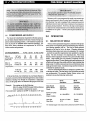
1.4 CQMPRESSED AIR SUPPLY
The volume of com pressed air required for efficient operation
of your Basket Blaster depends on the size of nozzles being used
and the desired operating pressure. 5/16" diameter nozzles with
5{32" air jets are the standard unless otherwise specified. The
chart below shows minimum air requirements in SCFM for
various nozzles and pressures.
40PSI
AIR REQUIREMENTS
884-1A
wlthree guns
(bold print)
1/4" noz
w/1/8" jet
60 PSI
80 PSI100 PSI
36
51
63
78
(24)
(34)
{42)
(52)
57
5116" noz.
882-1 A
w/5132" jet
wttwo guns
(regular print)
(38)
81
(54)
102
(68)
(84)
7/16" noz
w/7132" jet
114
(74)
156
(104)
198
(132)
240
(160)
126
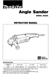
If the air line from your compressor to your Basket Blaster is
too small, excessive pressure drop through the line may result in
inefficient blasting even though the compressor is adequately
sized. Use the graph below to determine the proper air line size.
Example - Size piping run for the following:
BB4-1A using 102 SCFM located 100 feet distance
from the nearest compressed air source.
From chart below- piping run to BB4-1A should be 1-1/4" pipe
LEHGTH OF 2.~
50
75
ICO
125 !50
175 2m 225 Z50 :!75 300
AIR Ll NE CFTl
PIPE
1~
d'z
2
3
S1Z£-ZV4~-...:._--I-\-__;::.--+-........:::.--t---
2.0
2.1
OPERATION
SELECTION OF MEDIA
Next to choosing the proper equipment, selection of the proper
media is the most important factor in determining how efficient
your blasting operation will be. The kind of media selected
depends on the kind of job to be done. Cleaning, deburring,
smoothing sharp edges, paint removal, preparation for coatings
- each job has specific requirements best satisfied by specific
media. The size of media is very important also. Fine media
results in more impacts per second over a given area than large
media. Large media gives less number of impacts, but each
impact has more force. For easy blasting jobs such as the removal
of light rust from steel, fme media will give faster cleaning than
l.argemedia. Fordifficultjobssuchasremovalofmillscale,large
media gives better results. Sometimes large and fine medias are
combined for optimum results.
Your Pro-Finish Basket Blaster is designed to operate with a
wide range of media. The chart below lists which kinds of media
are recommended. The standard Basket Blaster system with
reclaimer can use the following media sizes:
60Hz
Operation
50 Hz
Operation
Glass Beads
Walnut Shells
Plastic
any size
larger than
200 MESH
any size
larger than
200 MESH
Aluminum Oxide
Garnet
Silicon Carbide
40-200 MESH
60-200 MESH
Steel Grit
Steel Shot
G-125 to G-200
S-70
Consult
Factory
For medias larger than those shown please consult the factory.
PRO·FINISH") BASKET BLASTERS
Spherical media such as glass beads are used for general
purpose cleaning and finishing where a satin like finish is desired
with little dimensional change. Glass beads are effective when
used with pressures in the 20-60 PSI range. Above 60 PSI
excessive breakdown or beads may occur.
Angular aggressive media such as aluminum oxide, steel grit
and garnet generally provide faster cleaning and produce a duller
fmish than glass beads. Aluminum oxide and steel grit are
suitable for use at pressures up to 100 PSI. Gamet breaks down
quickly at pressures greater than. 40 PSI.
Walnut shells or plastic media are sometimes used for delicate
pans or when a polished finish is desired. Pressures from 20~ 100
PSI may be used with these media depending on that application.
Dust from organic media, such as walnut shells, is flammable, as
is the dust from some plastic media. If these materials must be
used it is important that the cabinet and dust collector be cleaned
daily to remove any fme dust, which accumulates in hoppers,
crevices, and ledges.
When changing from one type media to another it is necessary
to thoroughly clean out the cabinet interior and media hoses to
avoid cross contamination.
2.2
USE OF HARSH MEDIA
Your Basket Blaster is designed for production use. Heavy
duty media return hose, urethane lined reclaimer, reclaimer wear
plate and tungsten carbide nozzles are furnished as standard
equipment If the media to be used is glass beads, no other wear
options are required. If the use or aluminum oxide or silicon
carbide is anticipated, it is highly recommended that optional
boron carbide nozzles be purchased.
2.3
MEDIA LOADING
With the cabinet switch "off", load media through the media
hopper access door (do not load media directly into the cabinet
hopper- this may clog the pneumatic duct). Approximately two
and one-half cubic feet of media is required to fully charge the
system. Operation with the system only partially charged may
cause starving of guns, since when the system is operating some
media is "lost" due to recirculation.
2.4
Operating Instructions
·
the basket be loaded at least 6" deep. Operating with to
few parts in the basket will result in premature basket c
cah(n_et wear. Maximum load of parts at one time is 3.
cubic feet (max. 350 lbs) in the BB4-1A, or 1. 7 cubic fet
(maximum 350 lbs.) in the BB2-1A.
E. Set the pressure regulator for the desired pressure. T
prevent excessive media consumption the blast pressur
should be within the following ranges:
Glass Beads .............................................................. 30 ~ 60 PS
Aluminum oxide or silicon carbide ....................... 30 ~ 100 PS
Gamet ....................................................................... 30 - 40 PS
Steel Shot or Steel Grit .......................................... 80 ~ 100 PS
Walnut shells or Plastic .......................................... 20 ~ 100 PS
F.
Set the control timer for the desired time. The proper tim
will vary depending on the part configuration, the quantit
of parts to be fmished and the surface fmish desired. Th
proper time must be determined by trial and error but fc
typical parts filling the basket 1/3 full the processing tim·
will be approximately 20-40 minutes.
2.5
EQUIPMENT SHUT DOWN
When the timed cycle is complete the blast guns and oscilla
tion will turn off automatically. The dust collector will continm
to run until the "stop" button is pushed.
2.6
EQUIPMENT ADJUSTMENTS
2.6.1
VENTILATION FLOW ADJUSTMENT
All Pro-Finish reclaimers are "Tunable". This means tha
they can be adjusted to control the average size of media retainec
in the reclaimer This adjustment is accomplished as describec
below:
A. Secondary air inlet closed ~ All particles except the very
fmest dust will drop into the media storage hopper. Normally if these dust particles are allowed to build up in the
media, blasting efficiency is decreased.
·
B. Secondary air inlet opened slightly- Some particles will be
carried to dust collector~ adjust so that only useful media is
retained.
C. Secondary air inlet completely open- Most if not all media
will be carried to dust collector.
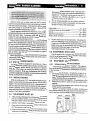
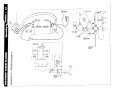
Below is a schematic diagram of cabinet, reclaimer and
dust collector showing the basic operation of the the system as
well as the flow of air and media before and after blasting.
EQUIPMENT START-UP
A. After checking all piping and hose connections to be certain
they are all tightly fastened - turn on plant compressed air
and open manual valve(s) controlling flow of air to system.
B. Depress "start" button - system dust collector will start
C. Open cabinet door and rotate Basket using jog button until
loa .... door moves to top front postion.
D. Remove the load door on the basket and load parts. Close
basket door. For maximum basket life it is important that
I 5
Cabinet
oust
Collector
I Operating Instructions
. 6
·.' :: :.: ':'·:·. ', ·" : :-" ..:_,_·
,.·.·.: .. ;..-:::· ·:;::::·.·:-··.
• ~· < . ·•· ...
2.6.2 MEDIA FLOW
The flow of media to suction blast guns is controlled by the
amount of air which enters through the inlet port in the media
regulator. The amount of air entering is controlled by how far the
blast hose is inserted within the abrasive regulator. For normal
operation, all but l/4" of the inlet port is blocked by the blast hose.
With fme media the 1/4" dimension may be varied slightly to give
uniform flow.
Note that it can easily be determined if media is flowing
properly by looking through the media regulator air inlet while
the system is operating.
2.6.3 GUN ADJUSTMENT
Adjustment of guns is normally not critical for proper operation. The tumbling action of parts within the basket is such that
proper coverage of parts can usually be obtained with almost any
gun orientation. However, for most efficient operation, guns
should be angled about 20° toward the back of the cabinet. As the
basket rotates parts tend to mass toward the back side, thus if the
guns are angled slightly in this direction they will be aimed at the
greatest mass of parts. This will help to give most efficient
blasting as well as maximum basket and or cabinet life.
On the BB4-1 A the oscillation stroke of the three guns is fixed.
The guns at either end should be angled slightly toward the ends
of the basket, not so much as to cause wear to the basket ends but
·enough to assure coverage of parts tumbling near the basket ends.
3.0
MAINTENANCE
PRO·FINISH® BASKEI BLASTERS
C. Shake dust collector bags after every 4 hours of operation.
Dust is removed from the bags by depressing the bag-shake
button 10 to.l5 times with the dust collector fan off.
D. Remove accumulated dust from the dust collector hopper.
E. Check light bulbs and gauntlets.
F Remove debris from reclaimer screen.
G Open the drain on the manual moisture separator in the
cabinet piping and drain ace urn ulated moisture. aose drain.
H. Open the drain valve on the the air compressor receiver tank
to drain any water which may have accumulated.
I. Check media level. For most efficient operation media level
should not decrease to less than 1(2 of recommended full
volume.
3.2 WEEKLY MAINTENANCE
A. Repeat recommended daily maintenance procedures.
B. Check nozzle for wear. When nozzle is worn 1/8" oversize,
replace. A drill bit can be used to check nozzle size.
C. Check air jet for wear. This is easily accomplished by
loosening the set screw in the side of the gun body and
removing jet. If the air jet shows wear, rotate it 90° from
current position, reinsert in gun and retighten set screw.
D. Check nozzle adapter and mixing head body for wear replace if necessary.
E. Check window gasket for leaks. Replace if necessary.
F. Check your spare parts inventory for replacement items.
G. Loosen the hose clamp on the 4" conveying hose and rotate
the hose 90° (this will allow the hose to wear evenly on both
sides).
3.3
3.1
DAILY MAINTENANCE
A. Check condition of media. If media is contaminated or
broken down into dust, clean out the system and reload (see
Section 2.3). Adjust tuning band if dusty condition is found
(see Section 2.6-1).
B. Inspect all media carrying hoses for wear by feeling along
the hose length for soft spots. If soft spots are found the hoses
should be replaced. Safety pin must be in place to prevent
quick coupling disconnection.
OTHER MAINTENANCE
A. Every 160 hours of operation grease t,;1e ui!ee shaft bearings
and the one idler arm assembly with any standard multipurpose grease. The one bearing on the left side is exposed.
The three remaining lube points can be reached by opening
the guard on the right side of the machine.
B. Every 160 hours of operation check the oil level in the gear
reducer by removing the high level plug. A<id gear oil as
necessary to maintain the oil level at the proper level.
PRO·FINISH~
BASKET BLASTERS
Operating Instructions·
3.4 STORAGE OR TEMPORARY NON-USE
l.
If the Basket Blaster is not to be used for a period of several
days or more, empty all media from the system. ·This can easily
be done by releasing the latches on the bottom of the quick dump
storage hopper. An optional dwnp cart is available which can be
wheeled under the storage hopper to catch and store the discarded
media.
4.0
DIAGNOSIS & REMEDY
- See pages 8 and 9
4.2
"ON-OFF" INTERLOCK SOLENOID
This solenoid is mounted outside the back of the control panel
and serves two functions:
A. It assures that the blast guns will only operate if the dust
collector is "on".
B. It provides an air signal to turn on the guns and start the
oscillation.
Operation of the this solenoid can be checked as follows:
A. With the dust collector "on", tum timer knob "on" then
"off". Each time the timer is turned off the hiss of escaping
air should be heard at the solenoid.
B. If no escaping air is heard, check to make sure the timer
contacts are closing properly. With the timer "on" there
should be continuity between terminals 3 and 6 (on the top
right terminal strip, D.Q.t the motor controller terminal strip).
If contacts do not close when timer is "on" - replace timer.
C. If the timer has been checked and found to be OK then
problem is a faulty solenoid - replace.
4.3
OSCILLATION (884-1 A only)
Your BB4-1A utilizes all pneumatic circuitry to oscillate the
three blast guns. The schematic for the oscillation circuit is
shown on drawing 5.4 attached. In the event that a component on
the oscillator malfunctions it would be normal for the other
cabinet functions to operate properly. If this is the case the
troubleshooting procedure below can be followed:
A. Check to be sure that oscillation mechanism is not jammed
inside the basket or elsewhere (with the cylinder clevis pin
removed this mechanism should move freely).
B. Check that the flow controls are open Qocated on the
cylinder pc•\ts· ~ item . J.: •'raw::-:g 5.4). Tum screws
counter-clockwise to open.
C. Check operation of sensor fittings (see item 5 on drawing
5.4)mouritedoneachendofthecylinder. Asthecylinderrod
reaches the end of its stroke the sensor fitting at that end
should shift and send an air signal to the 4-way valve causing
it to shift. To check the sensor fittings follow the procedure
described below.
7
.
If the cylinder rod is extended remove the top l/4'
tubing run on the sensor fitting farthest away from the
. ~abinet (each sensor fitting has two tubes - the tube!
can be removed by depressing the small brass collru
with the tip of a screwdriver and at the same tim<
pulling out on the tubing).
If the cylinder rod is retracted remove the top 1/4'
tubing run on the sensor fitting closest to the cabinet
TROUBLESHOOTING
4.1
I
2.
3.
4.4
With the dust collector "on", air should be flowing
from the open sensor port.
If air is flowing, the problem is a faulty 4-way valve
(item 9 on drawing). Disassemble and clean or re·
place. Note that the 4-way valve is the lapped spoo.
type and does not contain rubber seals or 0-rings.
If air does not flow from the open sensor port then the
problem is a faulty sensor fitting. Note that these
fittings cannot be disassembled for repair, however, i:
they are subjected to excessive moisture or oil they
will cease to work. In this case once the fitting is driec
out it will again work properly. However, for reliable
operation the cause of the air contamination must be
eliminated.
BASKET DRIVE
The basket rotates on two powered shafts each with two 5''
diameter rubber coated wheels. One shaft is directly connectec
to a gear reducer which is powered by a 1(2 HP D.C. motor. The
motor is powered by an adjustable speed D.C. motor controllet
mounted in the cabinet contol panel.
If the basket will not rotate but other cabinet functions (blast
guns, lights and oscillation) are OK, then follow the troubleshooting procedure below.
A Make sure both drive shafts are turning. If rear shaft turn~
but front shaft does not, then remove the guard on cabinet
right side and adjust idler sprocket
B Check for blown 10ampfusein frontofcontrolpanel. If fuse
is blown, correct the cause of the overload and replace the
fuse.
C. If fuse is intact check D.C. motor controller as follows:
1. Input to controller terminals 1 and 2 should measure
llOvolts to 125 volts.
2. During normal operation output of D.C. controller
(terminals 5 and 6 on controUer terminal strip) should
be about 90 volts. If output is not 90 volts, disconnect
motor leads (wires 10 and 11 connected to terminals 5
and 6 on motor controller terminal strip) and measure
resistance across motor .coil.. If motor coil is open,
motor is faulty. Repair or replace. If resistance of
approximately 7 ohms is measured, then motor is OK
and controller is faulty.
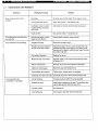
4.1
DIAGNOSIS AND REMEDY
TROUBLE
PROBABlE CAUSE
..
REMEDY
New Bags
Continue use until bag "cake' forms (approx 8 hrs.)
Tuning band open too far
Adjust tuning band- see Section 2.. 6.1
Insufficient media in suction
hopper allowing secondary
air to enter
Add media to maintain recommended media level
Media too fine
Use coarser media- see Section 2.1
Dust escaping to work area from
dust collector
Hole in dust bag(s) or loose
bag(s) in dust collector
Replace leaking bag(s) refasten bag(s)
Poor Ventilation during blasting
Clogged dust bags
Shake dust collector bags
"Blinded" dust bags (reduced
air flow due to age of bags)
Replace the bags-Over a period of years dust may
penetrate the fibers of the bags to the extent that air
flow through the bags is restricted even when the bags
are shaken regularly
Fan rotation backward
Reverse fan wiring
Media has high dust content
Replace media-Then adjust tuning band as shown
in Section 2.6.1
Return hose blocked
Remove return hose and inspect for obstruction
Cabinet alr inlet plugged
Blow filter clean with blowoff hose
Dust collector door leaks air
Tighten door, replace gasket if necessary
Operating air pressure too high
Decrease pressure to within recommended range
Low air pressure
Increase pressure within the range specified
Nozzles too small
Install larger nozzles and air jets-The smaller these
.are the less work is dona in a given time
Good media carried to Dust
Collector
Poor production rata
(continued on next page}
Improper media
See Section 2.1
Low media level
Add media to maintain recommended level
PRO·FINISH~"'
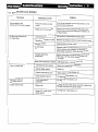
4.1
BASKET BLASTERs·
Operating Instructions
I
9
DIAGNOSIS AND REMEDY
TROUBLE
PROBABLE CAUSE
-.
REMEDY
Parts to be blasted are oily
or wet
Parts to be processed must be absolutely dry and
free of any oll, grease etc.
Media has high dust content
Remove old media and replace-Blasting media
breaks down and must be changed or added to on
a regular basis
Low media level
Add media to maintain recommended level
Operating air pressure too low
Maintain air pressure within the recommended range
Clogged nozzle
Disassemble and clean nozzle/
Damp media
Replace media-If media will form ball in palm of hand,
it is too damp to flow properly. Air comressor is
discharging moisture or work pieces damp or oily
Improper jet/nozzle
combination
Nozzle orifice size must be at least twice the air jet
orifice size. 1/8" dia. air jet requires at least 1/4"
dia. nozzle
Blast hose improperly installed
Adjust blast hose -see Section 2.6.2
Compressed air line closed
Open all air valves from compressor
Door not tightly closed
Close door
Regulator adjusted to zero
Adjust regulator-see Section 2.1
Faulty interlock solenoid
To diagnose-See Section 4.2
Blast guns work but
oscillation does not
Faulty component in
oscillation
To diagnose-sea Section 4.3
Basket will not rotate
Blown fuse
Correct the cause of the blown fuse then replace the
10 SMP fuse at front of control panel
Faulty D.C. motor or D.C.
motor control
To diagnose-See Section 4.4
Poor production rate
(continued from previous page)
Air flow, but intermittent or
no media flow
No air or media flow
:1.
I
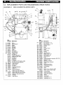
5.0
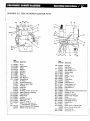
REPLACEMENT PARTS AND RECOMMENDED SPARE PARTS
Operating Instructions.
DRAWING 5.1
.
PRO·FINISHQ<' BASKET BLASTERS
BB4-1A BASKET BLASTER PARTS
31
«
3:1 215
24 2!5 23 22 21
Part
Part
Number Description
(1)
(2)
(3)
(4)
(5)
{6)
(7)
(8)
(9)
(10)
549561
570661
506871
570101
510081
510091
570771
570603
570611
140485
517271
517251
518401
517042
510511
550212
518041
(11) 290156
(12) 520551
(13) 522601
(14) 523051
(15) 766831
(16) 510511
(17) 505222
(18)
(19) 510651
509171
767141
(20) 532701
532711
Motor
Gear Reducer
Wheel
Bearing
Felt Seal
Sprocket
Chain
Idler Shaft
Idler Sprocket
Piping String
Air Filter, 1"
Pressure Regulator, 1"
Repair Kit for 517251
Air Valve, 1"
Safety Pin
Air Gauge
Air Filter, Ya" NPT (Before 8-89)
Media Regulator Assembly
Hose Clamp, 6"
Media Hose
Air Hose
Bearing (Oscillation)
Safety Pin
Quick Coupling, V2"
Media Guns (See page 14)
Basket Assembly (Uncoated)
Basket Assembly (PVC Coated)
Basket, V." dla. perforations
Spotlight
Light Fixture
(21)
Number
525901
525911
524451
510401
510461
760291
509371
Description
Door Gasket, 1" x 1"
Door Gasket, 1" x 1%''
Window Gasket
(22)
Window
(23)
Knob
(24)
Window Frame
(25)
Latch
(26)
Fitting Plate
(27) 50~381
(28) 751242 . Keeper
(29) 522953 Hose Clamp, 4"
(30) 516161 Media Hose, 4" ID
Dust Hose, 6" 10
(31) 515611
Hose Clamp, 6"
(32) 520551
(33) 531041 Timer
(34) 140483 Coated Reclaimer Assembly, 600 CFM
(35) 524371 Gasket, 15" dia
(36) 526161 Gasket, x o/• x 53
(37) 525821 Gasket (Gear Reducer)
(38) 766991 Chute
(39) 525841 Gasket (Parts Door)
(40) 521441 Hose (Dust-Off Gun)
Dust Off Gun
(41) 509821
(42) 518191 Valve
Motor Control (Before 9-89)
(43) 535271
Motor Control (After 8-89)
535003
Fuse (1 0 amp)
(44) 532281
(45) 518581 Valve (Oscitlation)
(46) 51.8571 Valve (Flow Control)
(47) 6~ 8561 Sensor
(48) 509221 Air Cylinder
(49) 523021 Polytubing, 1/4" x 7'
(60) 523041 Polytubing, %" x 4'
v.
PRO·FINISH:HJ BASKir BLASTERS
DRAWING 5.2
Operating Instructions
I :1.1.
'
BB2-"1A BASKET BLASTER PARTS
42
43
4,5
6
-7
41
8
9
3
Part
Number Description
(1)
(2)
(3)
(4)
(5)
(6)
(71
(8)
(9)
(10)
549561
570661
506871
570101
510081
510991
57o"Z.71
570603
570611
140485
517271
517251
518401
517042
510511
550212
518041
290156
520551
522581
523051
766831
510511
505222
(11)
(12)
(13)
(14)
(15)
(16)
(17)
(1 B)
(19) 767131
509281
767151
Motor
Gear Reducer
Wheel
Bearing
Felt Seal
Sprocket
Chain
Idler Shaft
Idler Sprocket
Piping String
Air Riter, 1"
Pressure Regulator, 1"
Repair Kit for 517251
Air Valve, 1"
Safety Pin
Air Gauge
Air Filter, Va" NPT (Before 8-89)
Media Regulator Assembly
Hose Clamp, 6"
Media Hose
Air Hose
Bearing (Oscillation)
Safety Pin
Quick Coupling, W'
Media Guns (See page 14)
Basket Assembly (Uncoated)
Basket Assembly (PVC Coated)
Basket, Va" dia perforated
Part
Number Description
(20) 532701
532711
(21) 525901
525911
(22) 524451
(23) 510401
(24) 510461
(25) 760291
{26) 509371
(27) 509381
(28) 751242
(29) 522953
(30) 516161
(31) 515611
(32) 520551
(33) 531041
(34) 109002
(35) 524371
(36) 526161
(37) 525821
(38) 766991
(39) 525841
(40) 521441
(41) 509821
(42) 518191
(43) 535271
535003
(44) 532281
(45) 523021
Spotlight
Light Fixture
Door Gasket, 1" x 1"
Door Gasket, 1" x 1W'
Window Gasket
Window
Knob
Window Frame
Latch
Fitting Plate
Keeper
Hose Clamp, 4"
Media Hose,4" ID
Dust Hose, 6" I D
Hose Clamp, 6"
Timer
Coated Reclaimer Assembly, 600 CFM
Gasket, 15" dia
Gasket, Y4 x ~ x 53
Gasket (Gear Reducer)
Chute
Gasket {Parts Door)
Hose (Dust-Off Gun)
Dust Off Gun
Valve
Motor Control (Before 9-89)
Motor Control (After 8-89)
Fuse (10 amp)
Polytubing, W' x 7'
12
I Operating lnstru~tions
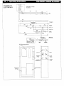
DRAWING 5.3
ELECTRICALS
I
DISCONNECT & FUSES
BY OTHERS
I
I
L
PRO·FINISH'j<) BASKET BLASTERS .
__ _j
1M
10L
H-+-'-"'-'------- 1------:.~ ·c-·:r-----~~~=1-+-t---'-1'='L:/."---------'
1------:.--r.'_-·
L..-.___.:.1=:1..3~----------, 1 - - - - - - r - )(_-
TJ
1
c;,
, MO;ORJ
'--/'
''"
MOTOFI
11.2
1L1
TRAHSP:ORMEA
1 K'IA
2
1T
STOI'
START
4
10L
3
+-----~~-~-~_i_~~~---------~
1PB
I.
2PB
~1----4--3________--4
1M
/
3
/
'II•
2
FAN MOTOR
STARTER
2
~T
'
2
CABINET LIGHT
•
~
JOG
3
~------~-+-~------------------~
1
v
:~a
CABINET I..IOHT
ON·OFF
SOLENOID
I
: r l - - - - - -2-
L------------------- ...J
BASKET DRIVE'
MOTOR CONfROL
SASKET
OC MOTOR
SPEED
{BASKET DRM)
DC MOTOR CONTROLLER
+
START
STOP
BLAST
TIMER
BASKET
MOTOR FUSE
FAN MOTOR
STARTER
TRANSFORMER
BASKET
JOG
------------------8 J~~~D
····--
--
/
-
/
----
--,'\
OOORlf<TERlOCK
/
D---- \
i · ·- -·. · -
/--,
!
\
llAUGEt10
/
mousr
COlLECTOR
SHAKER
FlOW
C:ONlAOl
<
,..J
_1::1?8-
Ill
SENSOR
FITIING
m
en
0
i=
<!
:::
:::>
w
z
c..
'
I
l ___
l
--r--"
l_ -~
J
OSCilLATING BLAST GUNS
···-~\,
BLOW· OFF
GUN
t
/~-+++----.
----- --------
~
1.0
CJ
z
5:
<!
0::
a
TO OUST
COtLECTOR
SHAKER
""'
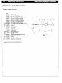
DRAWING 5.5
MH-2 SHORT HANDLE
MH-2 SHORT HANDLE
Part
Number
505571
505581
505601
505611
505541
505551
(1)
520402
(1 A) 544862
(2)
505621
(3)
523912
(4) 507391
505661
505671
505691
(4A) 526171
(5) 753561
(6)
(7)
(8)
(9)
(10)
505641
504931
523881
520081
551702
Description
Gun with 5/16" Di·Carb Nozzle
Gun with 7/16" Di·Carb Nozzle
Gun with 5116" Boron Nozzle
Gun with 7/16" Boron Nozzle
Gun with 5/16" Ceramic Nozzle*
Gun with 7/16" Ceramic Nozzle
Barbed Fitting (B82·1 A only)
Pipe Coupling, 1/2" NPT (884·1 A only)
Connector
"0" Ring
Air Jet 3/32"
Air Jet, 1/8"
Air Jet, 5/32"
Air Jet, 7/32"
Rubber Sleeve only
Gun Bodv (Short)
Nozzles
Plastic Nozzle Adapter (standard)
Steel Nozzle Adapter
"0" Ring
Hose Clamp Nut
Set Screw, 1/4"·20 x 3/8"
• Supplied with system unless otherwise specified.
\
1A
10
~-···---
8