1
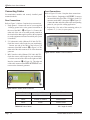
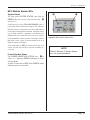
Intelligent Assembly Solutions iQ Series ULTRASONIC GENERATOR/POWER SUPPLY Auto AUTOMATED HAND PROBE PRESS User’s Manual Dukane Part No. 403 - 573 - 02 Dukane Intelligent Assembly Solutions • 2900 Dukane Drive • St. Charles, Illinois 60174 USA • TEL (630) 797 - 4900 • FAX (630) 797 - 4949 ISO 9001:2008 Products are manufactured in ISO registered facilities. www.dukane.com/us iQ Series, Auto User’s Manual Copyright © 2010 Notice of Rights: All rights reserved. No part of this manual including the interior design, cover design and icons may be reproduced, transmitted or utilized in any form or by any means, electronic, mechanical, photocopying, recording, or by any information storage and retrieval system, without written permission from the manufacturer. Notice of Liability: The information contained is this manual is distributed on an “As is” basis, without warranty. While every precaution has been taken in the preparation of this manual, the manufacturer shall not have any liability to any person or entity with respect to any liability, loss, or damage caused or alleged to be caused directly or indirectly by the instructions contained in this manual, or by the hardware products described herein. Specifications subject to change without notice. This user’s manual documents product features, hardware, and controls software available at the time this user's manual was published. Printed in the United States of America. Part Number: 403–573–02 This ultrasonic equipment is manufactured under one or more of the following U.S. Patents: 3,780,926 3,825,481 4,131,505 4,277,710 5,798,599 5,880,580 6,984,921, 7,225,965 7,475,801, and 7,819,158, B2 Page ii Dukane Manual Part No. 403-573-02 Revision History Revision Number Revision Summary Date Original release. 10/09/2007 - 01 20kHz and 30kHz models added. System I/O Connector signals modified. Amplitude control added. 08/27/2009 I/O Connector Pin 9 signal scale revised. 12/15/2010 - 00 - 02 Miscellaneous spelling errors corrected. Fig 5-1 and 5-2 dimensions edited. Fault conditions modified: Negative Peak Overload eliminated; Positive Peak Overload changed to Peak Overload; Frequency Lock Lost changed to Frequency Overload. Copyright page modified: Specifications subject to change statement added, and Patent 7,819,158 B2 added. Updated Dukane ISO certification statement to 2008. How to Lift Safely information added to Section 2, Health and Safety. International Protection Rating added to Section 5, Specifications. Dukane Manual Part No. 403-573-02 Page iii iQ Series, Auto User’s Manual This page intentionally left blank Page iv Dukane Manual Part No. 403-573-02 Contents Section 1- Introduction . . . . . . . . . . . . . . . . . . . . . . . . 1 General User Information . . . . . . . . . . . . . . . 3 Generator Overview . . . . . . . . . . . . . . . . . . . . 4 Key Generator Features . . . . . . . . . . . . . . . . . 4 Thermal Considerations . . . . . . . . . . . . . . . . . 5 Section 2- Health and Safety . . . . . . . . . . . . . . . . . . . 7 General Considerations . . . . . . . . . . . . . . . . 9 Plastics Health Notice . . . . . . . . . . . . . . . . . 9 Electrical Safety . . . . . . . . . . . . . . . . . . . . . 10 How to Lift Safely . . . . . . . . . . . . . . . . . . . . 11 Section 3- Installation . . . . . . . . . . . . . . . . . . . . . . . . 13 Unpacking . . . . . . . . . . . . . . . . . . . . . . . . . 15 Placing . . . . . . . . . . . . . . . . . . . . . . . . . . . . 15 Power Grounding . . . . . . . . . . . . . . . . . . . . 16 Chassis Grounding Stud . . . . . . . . . . . . . . 16 Connecting Cables . . . . . . . . . . . . . . . . . 17-19 MPC Module Installation Guide . . . . . . . 20-25 Section 4 - System Operation . . . . . . . . . . . . . . . . . 27 Standard iQ Auto System Test . . . . . . . . . . 29 iQ Auto System with MPC Test . . . . . . . . . . 30 Section 5 - Specifications . . . . . . . . . . . . . . . . . . . . . 33 Section 6 - Automation Interface . . . . . . . . . . . . . . . 41 Input/Output Connection Examples . . . . 43-44 E-Stop Circuitry Connection Examples . . . 46 Section 7 - Contacting Dukane . . . . . . . . . . . . . . . . . 47 Dukane Manual Part No. 403-573-02 Page iQ Series, Auto User’s Manual This page intentionally left blank Page vi Dukane Manual Part No. 403-573-02 Section 1 – Introduction SECTION 1 Introduction General User Information . . . . . . . . . . . . . . . . . . . 3 Read The Manual First. . . . . . . . . . . . . . . . . . . . . . 3 Notes, Cautions and Warnings. . . . . . . . . . . . . . . . . . 3 Drawings and Tables. . . . . . . . . . . . . . . . . . . . . . . 3 Generator Overview. . . . . . . . . . . . . . . . . . . . . . 4 Key Generator Features. . . . . . . . . . . . . . . . . . . . 4 Thermal Considerations. . . . . . . . . . . . . . . . . . . . 5 Dukane Manual Part No. 403-573-02 Page iQ Series, Auto User’s Manual This page intentionally left blank Page Dukane Manual Part No. 403-573-02 Section 1 – Introduction General User Information Read This Manual First Before operating your ultrasonic generator, read this User’s Manual to become familiar with the equipment. This will ensure correct and safe operation. The manual is organized to allow you to learn how to safely operate this generator. The examples given are chosen for their simplicity to illustrate basic operation concepts. Notes, Cautions and Warnings NOTE Note statements provide additional information or highlight procedures. Throughout this manual we use NOTES to provide information that is important for the successful application and understanding of the product. A NOTE block is shown to the right. In addition, we use special notices to make you aware of safety considerations. These are the CAUTION and WARNING blocks as shown here. They represent increasing levels of important information. These statements help you to identify and avoid hazards and recognize the consequences. One of three different symbols also accompany the CAUTION and WARNING blocks to indicate whether the notice pertains to a condition or practice, an electrical safety issue or an operator protection issue. CAUTION Caution statements identify conditions or practices that could result in damage to the equipment or other property. WARNING Warning statements point out conditions or practices that could result in personal injury or loss of life. Drawings and Tables The figures and tables are identified by the section number followed by a sequence number. The sequence number begins with 1 in each section. The figures and tables are numbered separately. The figures use Arabic sequence numbers (e.g. –1, –2, –3) while the tables use roman sequence numerals (e.g. –I, –II, –III). As an example, Figure 3–2 would be the second illustration in section three while Table 3–II would be the second table in section three. Condition or Practice Dukane Manual Part No. 403-573-02 Electrical Hazard Hearing Protection Page iQ Series, Auto User’s Manual Generator Overview • Line Voltage Regulation automatically maintains constant amplitude regardless of line voltage deviation. The available output power is maintained with any voltage input within the specified range. This provides consistent system performance regardless of line voltage fluctuations. It also eliminates the need for bulky, external constant–voltage transformers. • Load Regulation provides constant amplitude automatically regardless of power draw. The ultrasonic output amplitude level is held to within ±1% to provide weld process consistency and reduced weld cycle times. • Industrial Line–Power Source means that standard systems will operate worldwide at all industrial high line voltage levels, whether it is 200VAC @60Hz in Japan, 240VAC @50Hz in Europe or 208VAC @60Hz in the United States. There are no internal transformer taps to change for worldwide operation. This generator is designed for ultrasonic applications controlled by a Programmable Logic Controller (PLC). Using the available system control inputs and outputs, the generator can easily be integrated into a wide variety of automated systems. The generator design accepts several control input signals, provides system output signals, has a power status LED indicator, and an amplitude adjustment control. An optional Multi-Probe Control (MPC) interface module allows the generator to power multiple probes selected by an automated control system. This product’s rugged internal ultrasonic generator circuitry ensures a continuous resonant frequency lock at the start of each weld. Ultrasonic settings for the drive signal, phase delay angle, starting frequency and soft–start ramp parameters can be customized at the factory. (Contact your local Dukane sales representative for more information.) Users can modify generator performance to meet a wide variety of ultrasonic processing requirements if needed. The generator’s compact size allows multiple units to be placed into an industrial equipment cabinet, and the generator will operate at the same international line voltage input specifications as the other generators of this product family. It also includes an RFI line filter that passes strict CE test specifications for global applications. Key Generator Features • Compact Enclosure Size requires a small footprint for either vertical or horizontal mounting into your equipment cabinet. • Pulse Width Modulation incorporates patented circuitry giving the power supply the ability to efficiently change the output amplitude. This makes it possible to start large horns with reduced power. It also provides more power efficient switch-mode generator operation and increased reliability. • Linear Ramp Soft Start circuitry allows the acoustic stack to ramp up to operating amplitude smoothly, minimizing the startup surges and abnormal stress to the stack and generator. • Automatic Tuning tracks the resonant frequency of the acoustic stack (horn, booster, transducer) and adjusts the generator output frequency to match it. This is done for every weld cycle and eliminates the need to manually tune the generator. Page NOTE 120VAC is also available for these countries: United States of America, Canada, Mexico and Japan. • Amplitude Adjustment Control allows the peak -to-peak excursion of the horn at its workface to be adjusted between 20% and 100% of the horn’s nominal amplitude. • Multiple Electronic Overload protection circuits prevent instantaneous component failure in the event of extreme output overload conditions and rated overload power limit is based on the actual true RMS power output level. • CE Certification means that the system meets the required European standards to be sold and used in Europe. • ISO 9001 Certification means that this system has been manufactured to high quality standards and assures you of manufacturing excellence. Dukane Manual Part No. 403-573-02 Section 2 – Health & Safety Thermal Considerations Figure 1-1 shows the thermal capability of the generator with and without the cooling package. For further information about the cooling package, contact your local Dukane sales representative. The thermal design of this generator is for applications that require 600 watts or less of power at less than a 50% duty cycle. For applications that require higher duty cycles, an optional cooling package is available, Part Number 438962. The cooling package includes a heat sink that mounts to the rear of the generator (Refer to Figure 5-2). NOTE Add transducer cooling as necessary to keep front mass temperature to 100°F or less. Standard Generators Duty Cycle 100% 75% 65% 60% 55% 50% 100 200 300 400 500 600 300 400 500 600 Power (Watts) Generators with Optional Heatsink Duty Cycle 100% 75% 65% 60% 55% 50% 100 200 Power (Watts) Figure 1–1 Thermal and Power Considerations for iQ Auto Generators Dukane Manual Part No. 403-573-02 Page iQ Series, Auto User’s Manual This page intentionally left blank Page Dukane Manual Part No. 403-573-02 Section 2 – Health & Safety SECTION 2 Health and Safety General Considerations . . . . . . . . . . . . . . . . . . . . . . . . . . . . . . . 9 Plastics Health Notice . . . . . . . . . . . . . . . . . . . . . . . . . . . . . . . . 9 Electrical Safety . . . . . . . . . . . . . . . . . . . . . . . . . . . . . . . . . . . . 10 Power Grounding Connection . . . . . . . . . . . . . . . . . . . . . . . . . . . 10 How to Lift Safely . . . . . . . . . . . . . . . . . . . . . . . . . . . . . . . . . . 11 Dukane Manual Part No. 403-573-02 Page iQ Series, Auto User’s Manual This page intentionally left blank Page Dukane Manual Part No. 403-573-02 Section 2 – Health & Safety General Considerations Please observe these health and safety recommendations for safe, efficient, and injury-free operation of your equipment. In this manual, the term system refers to a complete group of components associated with the welding of plastic or metal parts, also known as an ultrasonic assembly system. A typical system consists of a generator and/or ultrasonic process controller, start and stop switches, power controls, connecting cables, and the probe assembly which includes the transducer, booster, horn and replaceable horn tip. Proper Installation - Operate system components only after they are properly installed and checked. No Unauthorized Modifications - Do not modify your system in any way unless authorized to do so by the manufacturer. Unauthorized modifications may cause injury to the operator and/or equipment damage. In addition, unauthorized modifications will void the equipment warranty. Keep the Cover On - Do not remove any equipment cover unless specifically directed to do so by the manufacturer. The generator produces hazardous electrical voltages which could cause injury. CAUTION Never operate the generator with the cover off. This is an unsafe practice and may cause injury. CAUTION Parts being joined ultrasonically sometimes vibrate at audible frequencies. Wear ear protection to reduce annoying or uncomfortable sounds. In addition, sound absorbing materials, enclosures or sound deflectors may be installed to reduce the noise level. Grounded Electrical Power - Operate this equipment only with a properly grounded electrical connection. (See Page 16 for grounding information.) Comply with Regulations - You may be required to add accessories to bring the system into compliance with applicable OSHA regulations for machine guarding and noise exposure. Plastics Health Notice Before using any ultrasonic welding system, be sure you are familiar with OSHA regulations from the U.S. Department of Labor about the particular type of plastic(s) you are using. When plastic materials are being processed, they may emit fumes and/or gases that could be hazardous. Make sure you have adequate ventilation whenever these plastics are processed. Dukane Manual Part No. 403-573-02 Page iQ Series, Auto User’s Manual Electrical Safety Power Grounding Connection Figure 2-1 illustrates how the AC line is connected. iQ Auto Power Inlet CAUTION If there is any question about grounding of your equipment and/or its electrical power source, contact a qualified electrician. L N CAUTION Pluggable AC Line Connector Figure 2–1 AC Line Connection Terminal L N Wire Color North America Europe Black Lt. Brown (Ground) Green Green w/yellow stripe (Neutral) White Lt. Blue (Live) For safe system operation: To avoid the risk of fire, electrical shock, serious injury or death, the power line safety ground must be securely connected to the center terminal on the (pluggable) AC line connector. Table 2-I Conventional Wire Color Code Page 10 Dukane Manual Part No. 403-573-02 Section 2 – Health & Safety How to Lift Safely • Before lifting, take a moment to think about what you’re about to do. • Examine the object for sharp corners, slippery spots or other potential hazards. Know your limit and don’t try to exceed it. • Ask for help if needed, or if possible, divide the load to make it lighter. • Know where you are going to set the item down, and make sure it and your path are free of obstructions. Then follow these steps: Step 1. Stand close to the load with your feet spread apart about shoulder width, with one foot slightly in front of the other for balance. CAUTION Take care in lifting the equipment. We recommend using a mechanical lift device to assist. Step 2. Squat down bending at the knees (not your waist). Tuck your chin while keeping your back as vertical as possible. Step 3. Get a firm grasp of the object before beginning the lift. Begin slowly lifting with your LEGS by straightening them. Never twist your body during this step. Step 4. Once the lift is complete, keep the object as close to the body as possible. As the load’s center of gravity moves away from the body, there is a dramatic increase in stress to the lumbar region of the back. Step 5. If you must turn while carrying the load, turn using your feet-not your torso. To place the object below the level of your waist, follow the same procedures in reverse order. Remember, keep your back as vertical as possible and bend at the knees. Dukane Manual Part No. 403-573-02 Page 11 iQ Series, Auto User’s Manual This page intentionally left blank Page 12 Dukane Manual Part No. 403-573-02 Section 3 – Installation SECTION 3 Installation Unpacking . . . . . . . . . . . . . . . . . . . . . . . . . . . . . . . . . . . . . . 15 Placing . . . . . . . . . . . . . . . . . . . . . . . . . . . . . . . . . . . . . . . . . 15 Power Grounding . . . . . . . . . . . . . . . . . . . . . . . . . . . . . . . . . 16 Chassis Grounding Stud . . . . . . . . . . . . . . . . . . . . . . . . . . . . 16 Connecting Cables . . . . . . . . . . . . . . . . . . . . . . . . . . . . . . . . 17 Standard Model Configuration . . . . . . . . . . . . . . . . . . . . . . . . . . 17 System I/O Connector Pinout . . . . . . . . . . . . . . . . . . . . . . . . . . . 18 Optional MPC Interface Model . . . . . . . . . . . . . . . . . . . . . . . . . . 20 MPC I/O Connector Pinout . . . . . . . . . . . . . . . . . . . . . . . . . . . . . 21 MPC Probe Control . . . . . . . . . . . . . . . . . . . . . . . . . . . . . . . . . . . 22 MPC Installation Guide . . . . . . . . . . . . . . . . . . . . . . . . . . . . . 23 Connecting Cables . . . . . . . . . . . . . . . . . . . . . . . . . . . . . . . . . . . 24 MPC Module Status LEDs . . . . . . . . . . . . . . . . . . . . . . . . . . . . . 25 Dukane Manual Part No. 403-573-02 Page 13 iQ Series, Auto User’s Manual This page intentionally left blank Page 14 Dukane Manual Part No. 403-573-02 Section 3 – Installation Unpacking Carefully open your shipping container, and make sure it contains the items shown on the shipping documents. Inspect all items, and report any missing items or damage immediately. Placing Make certain generator placement and cable routing do not interfere with normal operation. Maintain easy access to your equipment. The operator should have unobstructed access to cables and wiring. Two sets of removable mounting brackets are attached to the generator. (Refer to Figure 5-1, Generator Outline Drawing.) Use them to securely mount the unit vertically or horizontally in your equipment cabinet. If the generator is installed inside an enclosure with a door, be sure there is adequate clearance for the system cables with the door closed. Dukane Manual Part No. 403-573-02 Page 15 iQ Series, Auto User’s Manual Power Grounding For safety, the iQ Auto chassis must be properly grounded. The power line ground connection is located on the center screw terminal on the AC Power Inlet pluggable screw terminal connector. This system ground connection must be attached to an earth ground potential at the electrical box that supplies power to the enclosure or cabinet in which the iQ Auto system is installed. The ground connection should comply with all of the requirements specified by the National Electrical code and any other local codes or ordinances that are applicable. Chassis Grounding Stud Proper grounding for the generator chassis is essential for the effective suppression of electrical noise or RFI (Radio Frequency Interference). Every ultrasonic generator contains a RFI filter that blocks noise on the AC power line from entering the system control circuitry. This filter also prevents ultrasonic frequency noise from being fed back into the AC power line. For the RFI filter to operate effectively, it is necessary to correctly ground the system. The power line ground previously mentioned is mandatory. Additionally, the included grounding wire must be connected from the grounding stud connection (see Figure 31) to the nearest grounded metal pipe or equivalent earth ground. This will improve the chassis ground connection and may be needed in noisy industrial environments. CAUTION To minimize electrical noise and eliminate ground currents, ground the chassis as shown. Use a STAR configuration (shown below).Do not DAISY CHAIN the grounds. Chassis Grounding Stud Protective earth ground connection wire color: green or green with yellow stripe. Fixed Probe Mount or 2nd Chassis Grounding Stud #14 Gauge Stranded or Solid Wire Earth Ground 3rd Chassis Grounding Stud NOTE Chassis Grounding Stud The chassis grounding stud is used to attach a protective earth ground to the generator. This helps suppress electrical interference or radio frequency interference (RFI) that is common in an industrial environment. Stud location is shown in Figure 3-1 on the following page. Page 16 CAUTION If you have any questions about the grounding of your equipment and/or the electrical box, contact a qualified electrician. Dukane Manual Part No. 403-573-02 Section 3 – Installation Connecting Cables NOTE Standard Model Configuration Connecting Cables Complete three basic connections for the standard configuration as shown below: Two-piece pluggable terminal block connectors are used for the System I/O connections and the AC Power Inlet connections. This type of connector allows the wiring to be attached to the screw terminal connector, which plugs into the mating connector on the iQ Auto system front panel. In the event a field replacement unit is required, the screw terminal connectors with the wires can be easily detached and then plugged into the replacement unit. • AC Line Input • System Control Inputs/Status Outputs • Ultrasound Output • Grounding Details about the various system connectors and their pin assignments are covered in the next section. Step 1. Wire the AC line connector, and attach it to the generator’s power inlet connector, matching the power source line, ground, and neutral with the generator’s line, ground, and neutral connector pins - A in Figure 3–1. (See Figure 2-1 also.) NOTE AC Power Inlet Step 2. Wire the user-supplied automation system control inputs/status outputs to the CONTROL CONNECTOR, and attach it to the system I/O port B in Figure 3-1. Line voltage required for the generator is 200-240 VAC at 50/60 Hertz and 6.3 Amps, or 100-120VAC at 50/60 Hz and 15 Amps. The unit does not include a power switch, and is powered ON whenever the AC line power is live. The unit can be switched ON/OFF with a user-supplied AC circuit breaker wired to the AC power inlet connection. Step 3. Attach a high–voltage coaxial ultrasound cable (from the ultrasonic probe) to J1, the ultrasound output connector - C in Figure 3-1. Step 4. Connect the included ground wire from the grounding stud, D in Figure 3-1, to earth ground. 10.76 [273.30] TOP REAR MOUNTING BRACKET LOWER REAR MOUNTING BRACKET 9.38 [238.25] AMPLITUDE GROUNDING STUD 3.47 [88.14] IN [ mm ] 100% 20% 2.00 [50.8] 3.35 [85.09] U/S POWER STATUS (LED) SYSTEM I/O 2.00 [50.8] .75 [19.05] U/S CONNECTOR POWER INLET BASE MOUNTING BRACKETS(2) CONTROL CONNECTOR AMPLITUDE ADJUSTMENT CONTROL See NOTE on Page 22. Figure 3-1 Generator Front View - Standard Model Dukane Manual Part No. 403-573-02 Page 17 iQ Series, Auto User’s Manual System I/O Connector Pinout The SYSTEM I/O connector is a two-piece pluggable terminal block connector. Table 3-I lists the signal names and descriptions, with more detailed descriptions listed on the next page. Pin Signal Name 1 Enable Out (+22V Current Limited) 2 Enable In (Jumper to Pin1, without an E-Stop switch) 3 Overload Out (system overload status output) 4 U/S Status Out 5 Any Fault Out 6 Power OK Out 7 Output Common (chassis ground - non-isolated) 8 Spare Status Out (programmable status output) 9 Analog Power Out + (1mV = 1 Watt) 10 Analog Power Out - (analog monitor signal common, non-isolated) 11 Fault Reset Input 12 U/S Active Input 13 Input Common (electrically isolated from chassis ground) Table 3-I System I/O Connector Signals Page 18 Dukane Manual Part No. 403-573-02 Section 3 – Installation Pin 1 (Enable Out) This is a current limited voltage source output intended to connect to an E-Stop circuit. If an E-Stop circuit is not used, Pin 1 must be jumpered to Pin 2 for ultrasound operation to be enabled. Pin 2 (Enable In) The output from the E-Stop circuit is connected to this pin when an E-Stop circuit is used. Otherwise, this pin must be jumpered to Pin 1 for ultrasound operation to be enabled. See Figure 6-4 for E-Stop circuit wiring examples. Pin 3 (Overload Out) Pin 3 is a non-isolated digital NPN status output that activates when an output overload condition is tripped. This output will be an open circuit if an output overload condition is not tripped. This output will remain latched ON until the U/S Activate input is switched OFF and then ON again. Pin 4 (Ultrasound Active Status Output) Pin 4 is a non-isolated digital NPN status output that activates when the system is delivering ultrasonic power to the load attached to the ultrasound output connector. This output will be an open circuit when the ultrasound output is off. Pin 5 (Any Fault Out) Pin 5 is a non-isolated digital NPN status output that activates whenever any fault condition is detected that inhibits ultrasound output and normal system operation. This output will be an open circuit when no system fault conditions are active. Pin 6 (Power OK Out) Pin 8 (Spare Status Out) Pin 8 is not functional with the standard factory configuration. Pin 9 (Analog Power Out +) Pin 9 is a analog output signal proportional to the true RMS ultrasound power output level. This signal is scaled so 1mV = 1 Watt. Pin 10 (Analog Power Out -) Pin 10 is a signal ground (non-isolated chassis ground) for the Analog Power output signal on Pin 9. Pin 11 (Fault Reset Input) Pin 11 is an isolated input control signal that will reset any output faults when it is activated. It can be used by the automation control system to simplify PLC programming. Pin 12 (U/S Activate Input) Pin 12 is used to activate the generator ultrasound output. Activating this isolated control input will switch the ultrasound output ON, and deactivating this signal will switch ultrasound OFF. Pin 13 (Input Common) [Electrically connected to Pin 5 on MPC I/O connector if MPC Interface option is installed.] Pin 13 is electrically isolated from chassis ground. Using sourcing (PNP) output drivers, this common line would be connected to the automation system power supply common. Using sinking (NPN) output drivers, this common line would be connected to the automation system positive supply output. Refer to Section 6 for wiring examples to connect these input signals. Pin 6 is a non-isolated digital NPN status output that activates when no fault conditions are detected by any of the power fault detection circuits included in the system. This output will be an open circuit when any power related fault condition is detected. Pin 7 (Output Common) Pin 7 is connected to chassis ground. The non-isolated NPN status output signals can drive isolated PNP inputs on the automation control system. Refer to Section 6 for wiring examples to connect output signals. Dukane Manual Part No. 403-573-02 Page 19 iQ Series, Auto User’s Manual Optional Multi- Probe Control (MPC) Interface Model Details about the various system connectors and their pin assignments are covered in the next section. The iQ Auto MPC model includes an optional MPC Interface circuit board that powers and controls an external MPC multi- probe control module. This external module, (that can be ordered with a minimum of two probe controls up to a maximum of 16 probe controls), must be purchased in addition to generator Model 40AT060-2N-MO (iQ Auto with MPC option) for a fully functional MPC system. The connections needed for the MPC Interface board are described below. Connections required for the external MPC module are also described below. Step 5. MPC I/O - Wire the MPC control/input signals and status output signals terminal block to the user-supplied automation control system in Figure 3-2. Step 6. MPC INTERFACE - Attach one end of the MPC Interface cable (Dukane # 200-1408-XX) to the MPC Interface connector on the iQ Auto panel Optional MPC Interface Connections -F in Figure 3-2. Connect the other end of the cable to the MPC INTERFACE connector on the right rear of the MPC module. Complete the same basic connections used for the standard iQ Auto configuration as previously described. NOTE • AC Line Input • System Control Inputs/Status Outputs • Ultrasound Output • Grounding (optional) The MPC Interface cable is a separate line item on the iQ Auto system order. The -XX at the end of the cable number specifies cable length. This will vary depending on your MPC installation. In addition to completing Steps 1- 4 of the basic connections as previously described, complete Steps 5 and 6 to wire the MPC Control Inputs/Status Outputs as described below. NOTE Amplitude adjustment will affect ALL MPC points. AMPLITUDE ADJUSTMENT CONTROL AMPLITUDE GROUNDING STUD MPC I/O POWER STATUS (LED) E 100% 20% MPC INTERFACE SYSTEM I/O U/S U/S CONNECTOR POWER INLET CONTROL CONNECTOR OPTIONAL MPC CONNECTORS See NOTE on Page 22. Figure 3-2 Generator Front View - Optional MPC Model Page 20 Dukane Manual Part No. 403-573-02 Section 3 – Installation MPC I/O Connector Pinout The MPC I/O connector is a two-piece pluggable terminal block connector. Table 3-II lists the signal names and descriptions, with more detailed descriptions listed below. Pin Signal Name 1 Setup Bit 0 Input 2 Setup Bit 1 Input 3 Setup Bit 2 Input 4 Setup Bit 3 Input 5 Input Common 6 MPC Ready Out 7 Output Common Table 3-II MPC I/O Connector Signals Pin 1 (Setup Bit 0 Input) Setup Bit 0 is the least significant bit used to select different probe channels when a Multi-Probe Control (MPC) Interface is used. This MPC control bit is used on all MPC systems. Pin 2 (Setup Bit 1 Input) Setup Bit 1 is the second least significant bit used to select different probe channels when a MPC Interface is used. This MPC control bit is used on MPC systems with three or more channels. Pin 3 (Setup Bit 2 Input) Setup Bit 2 is the third least significant bit used to select different probe channels when a MPC Interface is used. This MPC control bit is used on MPC systems with five or more channels. Pin 5 (Input Common) [Electrically connected to Pin 13 on System I/O connector.] Pin 5 is electrically isolated from chassis ground. Using sourcing (PNP) output drivers, this common line would be connected to the automation system ground potential. Using sinking (NPN) output drivers, this common line would be connected to the automation system positive supply voltage output. Refer to Section 6 for wiring examples to connect input signals. Pin 6 (MPC Ready Out) Pin 6 is a non-isolated digital NPN status output that activates when the MPC control is ready to accept changes on the probe selection control bits and ready to start the next MPC welding cycle. This output will be an open circuit when the MPC system is not ready to accept changes to control input signals, and it is able to switch a sourcing PNP input ON or OFF. Any changes will be ignored until this status output signal activates to the ready state. This status output signal will also be open (MPC NOT READY) if a fault condition is detected inside the MPC system. If this status output will not activate, check for a RED fault status indication (SYSTEM STATUS LED) on the front panel of the MPC module. Pin 7 (Output Common) Pin 7 is connected to chassis ground. The non-isolated NPN status output signal can drive an isolated PNP input on the automation control system. Refer to Section 6 for wiring examples to connect output signals. Pin 4 (Setup Bit 3 Input) Setup Bit 3 is the second most significant bit used to select different probe channels when a MPC Interface is used. This MPC control bit is used on MPC systems with nine or more channels. Dukane Manual Part No. 403-573-02 NOTE The Input Common Pins: Pin 13 of the System I/O connector and Pin 5 on the MPC I/O connector are both electrically isolated from chassis ground, but they are connected together. Both of these signals must be connected to the same voltage potential, either automation system ground or the automation system positive supply voltage. Page 21 iQ Series, Auto User’s Manual MPC Probe Control When the optional MPC Interface and MPC I/O connectors are used, the generator has the capability of controlling as many as sixteen compatible probes. One probe can be turned on at a time while the sequence of probe activation is determined by the user’s automation. The table below shows how the setup bit inputs correspond to the probes. MPC 3 2 1 0 Probe Selected Off Off Off Off 1 Off Off Off On 2 Off Off On Off 3 Off Off On On 4 Off On Off Off 5 Off On Off On 6 Off On On Off 7 Off On On On 8 On Off Off Off 9 On Off Off On 10 On Off On Off 11 On Off On On 12 On On Off Off 13 On On Off On 14 On On On Off 15 On On On On 16 NOTE Ultrasound Output Connector The ultrasound output connector used with all standard generators is a high voltage (5000V) coaxial style SHV-BNC connector. This connector provides superior shielding of electrical noise, compared to other types of connectors. The ultrasound output connector mates with fully shielded coaxial ultrasound cables that are secured with a simple and reliable quarter-turn bayonet style attachment mechanism. The ultrasonic output from this connector (that drives the attached ultrasonic load) is a very high AC voltage (1200VAC). At high power levels this can exceed 2 amps of current and must be securely terminated via the ultrasound cable for safe operation. Use original equipment ultrasound cables for safe and reliable system operation. Improperly assembled ultrasound cables can result in high voltage arcing and will destroy the ultrasound connectors. Table 3-III MPC Setup Bit Inputs Page 22 Dukane Manual Part No. 403-573-02 Section 3 – Installation MPC Module Installation Guide Cut Outs For panel mounted modules: MPC modules are designed for assembly systems where one ultrasonic generator is sequenced to as many as 16 ultrasonic probes. The MPC module is typically supplied as a stand-alone bench-top unit, or as a component that can be mounted in a through-panel configuration. Use Figure 3-3 below to determine the size of the cut needed for your equipment panel. Make the appropriate cut, and install the MPC module securing the mounting flange to the equipment panel before continuing with the cable connections. No special installation is needed for a stand-alone MPC module that can be put on a bench top or a shelf. Use the following installation recommendations for a panel mounted MPC module. 0.25 [06.35] C C/2 (6 PLCS) D A MODEL "A" "B" "C" "D" MPC0404 7.12 [181 mm] 1.75 [45 mm] 6.75 [171.5 mm] 2.25 [57.2 mm] MPC0808 10.88 [277 mm] 1.75 [45 mm] 10.50 [266.7 mm] 2.25 [57.2 mm] MPC1616 18.25 [464 mm] 1.75 [45 mm] 18.00 [457.2 mm] 2.25 [57.2 mm] Figure 3-3 MPC Module Cutout Guide Dukane Manual Part No. 403-573-02 Page 23 iQ Series, Auto User’s Manual Connecting Cables Front Connections For stand-alone modules and securely installed panel mounted modules: Refer to Figure 3-5 below. Complete these connections. 1. Probe Cable(s) - Beginning with PROBE 1, connect one end of the cable (See Table 3-IV below.) to the U/S connector on the MPC’s front panel - D in Figure 3-5. Connect the other end of the cable to the corresponding probe for your specific welding application. Rear Connections Refer to Figure 3-4 below. Complete these connections. 1. Earth ground - Connect one end of a user-supplied 14-Gauge ground wire to the ground connection at the rear of the MPC - A in Figure 3-4. Connect the other end of the wire to an earth ground potential at the electrical box that supplies power to the equipment (or to the equipment enclosure into which your system is installed). 2. Repeat Step 1 for each of the remaining probes (in sequence: 2, 3, 4, etc.) in your system. 2. U/S (ultrasonic) cable (Dukane P/N 200-479-XX Order the correct cable length for your installation.) - Connect one end of the cable to the left rear U/S connector of the MPC module- B in Figure 3-4. The other end of the cable connects to J1 of the ultrasonic generator. 3. MPC Interface cable (Dukane P/N 200-1408-XX Order the correct cable length for your installation.) - Connect one end of the cable to the right rear MPC D Figure 3-5 MPC Module Front Connectors Interface connector- C in Figure 3-4. The other end of the cable connects to the MPC INTERFACE connector on the ultrasonic generator. B A C Figure 3-4 MPC Module Rear Connectors System Frequency Probe P/N Cable P/N : MPC to Probe 20kHz 41Q20RE or 41Q20RS 200-479-XXM 30kHz 41A60E or 41A60S 200-479-XXM 40kHz 41A40 200-615-XXM Table 3-IV Probe Cables Page 24 XX = length in meters Dukane Manual Part No. 403-573-02 Section 3 – Installation MPC Module Status LEDs E System Status F The front panel SYSTEM STATUS LED lights up GREEN when the system is powered and ready in Figure 3-6. E If this LED is lit with a YELLOW/ORANGE color, a recoverable fault condition has tripped. This indicates that the system is operational, but a fault condition has occurred preventing normal operation. Examples of this type of fault would be a generator overload that will automatically reset when the next weld cycle begins, or the automation control system is selecting a channel that doesn’t exist - trying to select channel 10 for an 8 channel system, for instance. If this LED lights up RED, a hardware fault has been sensed, and the unit should be returned to Dukane for servicing. Probe Selection Status The PROBE SELECTION STATUS LED - F in Figure 3-6 - lights up GREEN indicating it is the selected probe. A probe’s LED turns to RED (from GREEN) when ultrasonic power is activated. Dukane Manual Part No. 403-573-02 Figure 3-6 MPC Module Status LED’s NOTE Refer to Section 4, System Operation, for more information. Page 25 iQ Series, Auto User’s Manual This page intentionally left blank Page 26 Dukane Manual Part No. 403-573-02 Section 4 –System Operation SECTION 4 System Operation Standard iQ Auto System Operational Test . . . . . . . . . . . . . . . 29 iQ Auto System with MPC Operational Test . . . . . . . . . . . . . . 30 Dukane Manual Part No. 403-573-02 Page 27 iQ Series, Auto User’s Manual This page intentionally left blank Page 28 Dukane Manual Part No. 403-573-02 Section 4 –System Operation Standard iQ Auto System Operational Test Step 1. Verify that the standard system installation is complete and all cables are connected. Refer to installation instructions included in Section 3, if needed. Refer to Section 6 - Automation Interface -for information on wiring system controls, if needed. Step 2. After completing Step 1, activate line power to the standard iQ Auto system. Normal Condition: GREEN - The POWER STATUS LED on the iQ Auto panel should light up GREEN. POWER STATUS LED The system is now ready to operate. Figure 4-1 Generator POWER STATUS LED Detail Troubleshooting Abnormal iQ Auto System Conditions Options for U/S Activation Connections: RED - If the POWER STATUS LED lights up RED, check line voltage level. Optionally, monitor the U/S Active status output on I/O connector Pin 4. GRAY - If the POWER STATUS LED is a gray color (not lit), check line input. This NPN status output signal will activate when U/S is ON. Step 4. Other Options the Operator can Check: Optional System Status Output to Monitor: • Fault Status output signals Fault Status output signals are available for: Optionally the Power OK status output can be monitored on I/O connector Pin 6. Overload (Pin 3), or This NPN status output signal will activate when power is OK. Any Fault (Pin 5). Step 3.After completing Step 2, test ultrasound output by activating I/O connector Pin 12. These NPN status outputs will activate when there is a fault: An Overload Fault latches until the next time U/S is activated, or Fault Reset Input is activated.. Normal Condition: The system is operating properly when power is delivered to the attached stack. Any Fault status activates when any fault is detected by the system. It latches until the start of the next cycle, or Fault Reset Input is activated. Ultrasound Activation Connections: Usually an automated control system is wired to this control input. Continued Optionally - A manual switch could be wired to this control input. Dukane Manual Part No. 403-573-02 Page 29 iQ Series, Auto User’s Manual Continued from previoius page Five fault conditions are monitored by the iQ Auto system for Any Fault: Troubleshooting Abnormal iQ Auto System Conditions RED - If the POWER STATUS LED lights up RED, check line voltage level. • Average Overload (Automatically resets on next cycle, or until an activation of Fault Reset Input) GRAY - If the POWER STATUS LED is a gray color (not lit), check line input. • Peak Overload (Resets same as Average Overload) • Overtemperature Troubleshooting Abnormal MPC Module Conditions MPC Module SYSTEM STATUS LED is ORANGE/YELLOW (resettable fault): (Automatically resets on cool-down) • Power Not OK • Check for an iQ Auto overload on the previous (AC line voltage under 180VAC) welding cycle. • Check for an invalid channel selection input • Frequency Overload control code - selection code is greater than the number of installed channels. (Automatically resets on next cycle, or until an activation of Fault Reset Input) iQ Auto System with MPC Operational Test Check for POWER OK fault on the iQ Auto System. Step 1. Verify that the system installation (with the MPC option) is completed and all cables are connected. Refer to the iQ Auto installation instructions in Section 3, if needed. Refer to Section 6 - Automation Interface - for information on wiring system controls, if needed. Step 2. After completing Step 1, activate line power to the standard iQ Auto system. Normal Condition: The POWER STATUS LED on the iQ Auto front panel should light up GREEN. MPC SYSTEM STATUS LED is RED (non-recoverable fault. • Resolve any iQ Auto power problem first. • There could be a circuit failure in the MPC module. If a circuit failure is discovered, return the MPC Module to Dukane for service. Step 3. After completing Step 2, test ultrasound output by activating I/O Connector Pin 12. Normal Condition: The system is operating properly when power is delivered to the attached stack. Ultrasound Activation Connections: The MPC module SYSTEM STATUS LED should light up GREEN. Usually an automated control system is wired to this control input. The system is ready to operate when both status LEDs light up GREEN. Optionally - A manual switch could be wired to this control input. Continued Page 30 Dukane Manual Part No. 403-573-02 Section 4 –System Operation Continued from previoius page Options for U/S Activation Connections: Step 5. Check MPC Channels Check that all MPC channels can be selected and activated. The automation control system activates input selection bits. Select a channel: PROBE SELECTION STATUS indicator illuminates GREEN when it is the selected channel. Activate ultrasound: Activate the iQ Auto ultrasound output on I/O connector Pin 12. The PROBE SELECTION STATUS indicator on the selected channel should switch to RED (from GREEN). The probe on the selected channel should deliver ultrasonic power. Repeat this test for all MPC channels. • Optionally monitor the U/S Active status output on I/O connector Pin 4. This NPN status output signal will activate when U/S is ON. • Optionally monitor the MPC Ready status output on MPC I/O connector Pin 6. This NPN status output signal will activate when the MPC is ready. Step 4. Other options the operator can check: • Fault Status output signals Fault Status output signals are available for Overload (Pin 3) or Any Fault (Pin 5). These NPN status outputs will activate when a fault occurs: An Overload Fault latches until the next time U/S is activated, or the Fault Reset Input is activated. Any Fault status activates when any fault is detected by the system. The output will latch until U/S is activated or the Fault Reset Input is activated. Five fault conditions are monitored by the iQ Auto system for Any Fault: • Average Overload (Automatically resets on next cycle, or until an activation of Fault Reset Input) • Peak Overload (Resets same as Average Overload) • Overtemperature (Automatically resets on cool-down) • Power Not OK (AC line voltage under 180VAC) • Frequency Overload (Automatically resets on next cycle, or until an activation of Fault Reset Input) Dukane Manual Part No. 403-573-02 Page 31 iQ Series, Auto User’s Manual This page intentionally left blank Dukane Manual Part No. 403-573-02 Page 32 Section 5 – Specifications SECTION 5 Specifications Generator Outline Drawings . . . . . . . . . . . . . . . . . . . . . . . 35-36 Weight . . . . . . . . . . . . . . . . . . . . . . . . . . . . . . . . . . . . . . . . . . . 37 Operating Environment . . . . . . . . . . . . . . . . . . . . . . . . . . . . . . 37 AC Power Requirements . . . . . . . . . . . . . . . . . . . . . . . . . . . . . 38 Regulatory Agency Compliance . . . . . . . . . . . . . . . . . . . . . . . 39 Dukane Manual Part No. 403-573-02 Page 33 iQ Series, Auto User’s Manual This page intentionally left blank Dukane Manual Part No. 403-573-02 Page 34 ALLOW 3.00" [76.2 mm] FOR CABLE CONNECTOR Dukane Manual Part No. 403-573-02 3.35 [85.09] IN [ mm ] 4.50 [114.3] .75 [19.05] 2.00 [50.8] BASE MOUNTING BRACKETS(2) 3.47 [88.14] TOP REAR MOUNTING BRACKET 9.75 [247.65] OAL POWER INLET POWER STATUS GROUNDING STUD 10.76 [273.30] SYSTEM I/O MPC I/O CONTROL CONNECTOR 9.38 [238.3] 10.73 [272.54] 10.61 [269.49] 11.25 [285.75] 100% 2.00 [50.8] U/S CONNECTOR All mounting holes are 0.219 inch diameter for M5 or #10 screws. NOTE: U/S OPTIONAL MPC CONNECTORS MPC INTERFACE 20% AMPLITUDE 1.44 [36.58] 7.38 [187.45] BOTTOM REAR MOUNTING BRACKET 6.00 [152.4] .91 [23.11] Section 5 – Specifications Figure 5-1 Generator Outline Drawing Page 35 ALLOW 3.00" [76.2 mm] FOR CABLE CONNECTOR OPTIONAL HEAT SINK KIT - 438-962 2.05 [52.1] 0.38 [9.7] 2.00 [50.8] .75 [19.05] 3.35 [85.09] BASE MOUNTING BRACKETS (2) IN [ mm ] 3.47 [88.14] TOP REAR MOUNTING BRACKET 9.75 [247.7] OAL 9.02 [229] 1.20 [30.5] 4.50 [114.3 1.21 [30.7] POWER INLET 10.76 [273.30] SYSTEM I/O 9.38 [238.3] 10.73 [272.54] CONNECTOR CONTROL 6.00 [152.4] 20% 100% 1.44 [36.6] 7.38 [187.5] 0.91 [23.1] 2.00 [50.8] U/S CONNECTOR NOTE: ALL MOUNTING HOLES ARE .219 DIA. FOR M5 OR #10 SCREWS. BOTTOM REAR MOUNTING BRACKET 6.00 [152.4] OPTIONAL MPC CONNECTORS U/S 10.62 [269.7] AMPLITUDE 11.25 [285.8] iQ Series, Auto User’s Manual Figure 5-2 Generator with Optional Heat Sink Outline Drawing Dukane Manual Part No. 403-573-02 Page 36 Section 5 – Specifications Weight Standard Model: 7 pounds (3.18 kg) Model with MPC Option : 8 pounds (3.63 kg) Shipping: Add 5 pounds (2.3 kg) to unit weight for packing materials. Operating Environment Operate the generator within these guidelines: Temperature: 40°F to 100°F (+5°C to +38°C) Air Particulates: Keep the equipment dry. Minimize exposure to moisture, dust, dirt, smoke and mold. Humidity: 5% to 95% non–condensing @ +5°C to +30°C Nonoperating storage guidelines: Temperature: -4°F to 158°F (-20°C to +70°C) Air Particulates: Keep the equipment dry. Minimize exposure to moisture, dust, dirt, smoke and mold. Humidity: 5% to 95% non–condensing @ 0°C to +30°C Dukane Manual Part No. 403-573-02 Page 37 iQ Series, Auto User’s Manual AC Power Requirements Operating Frequency Generator Model Number Overload Power Ratings (Watts) Input AC Power Requirements Nominal AC Volt @ Maximum RMS Current 20kHz 20AT060-1X-XX 600 100-120V 50/60 Hz @ 15 Amps 20kHz 20AT060-2X-XX 600 200-240V 50/60 Hz @ 6.3 Amps 30kHz 30AT060-1X-XX 600 100-120V 50/60 Hz @ 15 Amps 30kHz 30AT060-2X-XX 600 200-240V 50/60 Hz @ 6.3 Amps 40kHz 40AT060-1X-XX 600 100-120V 50/60 Hz @ 15 Amps 40kHz 40AT060-2X-XX 600 200-240V 50/60 Hz @ 6.3 Amps North America/ Japan AC Outlet Rating 15 Amps Table 5-I AC Power Requirements NOTE Standard iQ Auto model = XXAT060-XN iQ Auto with MPC model = XXAT060-XN-M0 Dukane Manual Part No. 403-573-02 Page 38 Section 5 – Specifications Regulatory Agency Compliance FCC CAUTION The generator complies with the following Federal Communications Commission regulations. • The limits for FCC measurement procedure MP-5, “Methods of Measurement of Radio Noise Emissions from ISM Equipment”, pursuant to FCC Title 47 Part 18 for Ultrasonic Equipment. CE Marking DO NOT make any modifications to the generator or associated cables as the changes may result in violating one or more regulations under which this equipment is manufactured. This mark on your equipment certifies that it meets the requirements of the EU (European Union) concerning interference causing equipment regulations. CE stands for Conformité Europeéne (European Conformity). The generator complies with the following CE requirements. • • • The EMC Directive for Heavy Industrial — EN 61000-6-4: 2001 EN 55011: 2003 EN 61000-6-2: 2001 EN61000–4–2 EN61000–4–3 EN61000–4–4 EN61000–4–5 EN61000–4–6 EN61000–4–8 EN61000–4–11 2 0 0 4 / 1 0 8 / E C The Low Voltage Directive 2006/95/EC. The Machinery Directive 2006/42/EC. EN 60204: 2006 Safety of Machinery - Electrical Equipment of Machines Part 1: General Requirements. IP (International Protection) Rating The iQ generator has an IP rating from the IEC (International Electrotechnical Commission). The rating is IP2X, in compliance with finger-safe industry standards. Dukane Manual Part No. 403-573-02 Page 39 iQ Series, Auto User’s Manual This page intentionally left blank Page 40 Dukane Manual Part No. 403-573-02 Section 6 – Automation Interface SECTION 6 Automation Interface Input/Output Connection Examples . . . . . . . . . . . . . . . . . . . . 43 PNP (Sourcing) Type Input Circuit . . . . . . . . . . . . . . . . . . . . . . . 43 NPN (Sinking) Type Input Circuit . . . . . . . . . . . . . . . . . . . . . . . . 44 NPN Type Output Circuit . . . . . . . . . . . . . . . . . . . . . . . . . . . . . . 45 E-Stop Circuitry . . . . . . . . . . . . . . . . . . . . . . . . . . . . . . . . . . . 46 Dukane Manual Part No. 403-573-02 Page 41 iQ Series, Auto User’s Manual This page intentionally left blank Page 42 Dukane Manual Part No. 403-573-02 Section 6 – Automation Interface PNP (Sourcing) Type Input Circuit System I/O Connector iQ Auto Ground +DC (Pin 13) Input Common (Pin 12) U/S Activate (Pin 11) Fault Reset (same as above) Input Voltage Range DC 24V ± 10% Input Current 10mA(typ) @ DC 24V input Figure 6-1 PNP Type Input Circuit Dukane Manual Part No. 403-573-02 Page 43 iQ Series, Auto User’s Manual NPN (Sinking) Type Input Circuit System I/O Connector iQ Auto Ground +DC (Pin 13) Input Common (Pin 12) U/S Activate (Pin 11) Fault Reset (same as above) Input Voltage Range DC 24V ±10% Input Current 10mA(typ) @ DC 24V input Figure 6-2 NPN Type Input Circuit Page 44 Dukane Manual Part No. 403-573-02 Section 6 – Automation Interface NPN Type Output Circuit System I/O Connector iQ Auto Ground Gate Drive (same as above) Overload (Pin 3) L U/S Status (Pin 4) L (same as above) Any Fault (Pin 5) (same as above) Power OK (Pin 6) +DC Output Common (Pin 7) Rated Output Voltage DC 24V ± 10% Maximum Output Current 500mA/1 Output Output Driver N Channel Power MOSFET Figure 6-3 NPN Type Output Circuit Dukane Manual Part No. 403-573-02 Page 45 iQ Series, Auto User’s Manual Dedicated E-Stop Switch Wiring Diagram System I/O Connector iQ Auto (Pin 1) Enable Out User supplied E-stop switch (Pin 2) Enable In Automation System Safety Circuit Wiring Diagram iQ Auto System I/O Connector (Pin 1) Enable Out (Pin 2) Enable In Relay contact block Master control relay User automation control hardware Figure 6-4 E-Stop Circuitry Page 46 Dukane Manual Part No. 403-573-02 Section 7 – Contacting Dukane SECTION 7 Contacting Dukane Dukane Manual Part No. 403-573-02 Page 47 iQ Series, Auto User’s Manual This page intentionally left blank Page 48 Dukane Manual Part No. 403-573-02 Section 7 – Contacting Dukane Contacting Dukane Identify Equipment When contacting Dukane about a service–related problem, be prepared to give the following information: • Model number, line voltage and serial number. • Fault status. • Problem description and steps taken to resolve it. Many problems can be solved over the telephone, so it is best to call from a telephone located near the equipment. Intelligent Assembly Solutions Mailing Address: Dukane Ultrasonics 2900 Dukane Drive St. Charles, IL 60174 USA Phone: (630) 797–4900 E-mail: [email protected] Fax: Main (630) 797–4949 Service & Parts (630) 584–0796 Website The website has information about our products, processes, solutions, and technical data. Downloads are available for many kinds of literature. Here is the address for the main website: www.dukane.com/us/ You can locate your local representative at: www.dukane.com/us/sales/intsales.htm Dukane Manual Part No. 403-573-02 Page 49 iQ Series, Auto User’s Manual This page intentionally left blank Page 50 Dukane Manual Part No. 403-573-02 Dukane ISO ISO CERTIFICATION Dukane chose to become ISO 9001:2008 certified in order to demonstrate to our customers our continuing commitment to being a quality vendor. By passing its audit, Dukane can assure you that we have in place a well–defined and systematic approach to quality design, manufacturing, delivery and service. This certificate reinforces Dukane's status as a quality vendor of technology and products. To achieve ISO 9001:2008 certification, you must prove to one of the quality system registrar groups that you meet three requirements: 1. Leadership 2. Involvement 3. Quality in Line Organizations and Quality System Infrastructure. The ISO 9001:2008 standard establishes a minimum requirement for these requirements and starts transitioning the company from a traditional inspection–oriented quality system to one based on partnership for continuous improvement. This concept is key in that Dukane no longer focuses on inspection, but on individual processes. Dukane's quality management system is based on the following three objectives: 1. Customer oriented quality. The aim is to improve customer satisfaction. 2. Quality is determined by people. The aim is to improve the internal organization and cooperation between staff members. 3. Quality is a continuous improvement. The aim is to continuously improve the internal organization and the competitive position. ISO 9001:2008 CERTIFIED Dukane products are manufactured in ISO registered facilities. Please refer to our website at: www.dukane.com/us/sales/intsales.htm to locate your local representative. iQ Series, Ultrasonic Generator/Power Supply Auto User's Manual Part No. 403-573-02 www.dukane.com/us Printed in the United States of America Dukane Intelligent Assembly Solutions • 2900 Dukane Drive • St. Charles, Illinois 60174 USA • TEL (630) 797- 4900 • FAX (630) 797- 4949