1
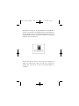
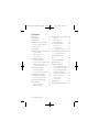
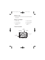
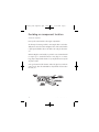
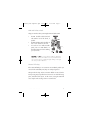
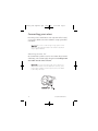
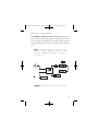
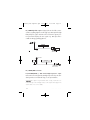
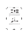
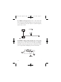
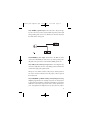
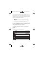
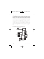
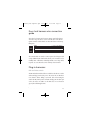
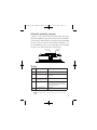
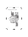
N3001L_2009-04print.qxd
5/12/2009
11:14 AM
Page 1
3001L Security System
installation guide
Note: This product is intended for installation by a professional installer only! Any attempt to install this product by
any person other than a trained professional may result in
severe damage to a vehicle’s electrical system and components.
© 2009 Directed Electronics, Vista, CA N3001L 2009-04
N3001L_2009-04print.qxd
5/12/2009
11:14 AM
Page 2
Bitwriter®, Code Hopping™, Doubleguard®, ESP™, FailSafe®, Ghost
Switch™, Learn Routine™, Nite-Lite®, Nuisance Prevention® Circuitry,
Revenger®, Silent Mode™, Soft Chirp®, Stinger®, Vehicle Recovery
System®, VRS®, and Warn Away® are all Trademarks or Registered
Trademarks of Directed Electronics.
The Bitwriter® (p/n 998U)
requires chip version 2.5 or
newer to program this unit.
Bitwriters with date code of 6A or older require an IC upgrade (p/n
998M). Some Bitwriters with a date code of 6B do not require the IC
upgrade. Refer to Tech Tip # 1112 for more information. Bitwriter 2
compatible.
N3001L_2009-04print.qxd
5/12/2009
11:14 AM
Page i
Contents
What is new
3
What is included
3
Control module
3
Installation points to remember
Before you begin installation
After the install
4
4
5
Tools required
5
Deciding on component location
6
Control module
6
LED and Valet switch
7
Starter kill relay
7
Connecting your wires
8
Four-pin optional sensor harness
RED wire
24
24
BLACK wire
24
BLUE, GREEN wires
24
Door lock learn routine
24
To learn lock:
25
To learn unlock
25
To exit the learn routine
26
On-board dual stage shock sensor 27
Shock Adjustment Mode:
27
Internal polarity jumper
29
Zones
29
Long term event history
30
Find the 12V switch ignition wire 9
Rapid resume logic
30
Find a parking light wire
10
Feature programming
Find the door pin switch circuit
11
Feature programming routine
Main harness wire guide
12
Once a feature is programmed
32
Main harness diagram
12
Accessing additional features
32
Accessing feature menu 2
32
Obtaining constant 12V
8
Main harness connection guide 13
31
31
18
Exiting feature programming
33
Auxiliary harness diagram
18
Bitwriter ONLY features
34
Keyless entry system types
21
Feature menu 1
35
Auxiliary harness wire guide
Door lock harness wire guide
Plug-in harnesses
23
23
LED and Valet switch
23
Data port—Bitwriter
24
© 2009 Directed Electronics
Feature menu 2
36
Troubleshooting
37
Wiring quick reference guide
40
i
N3001L_2009-04print.qxd
ii
5/12/2009
11:14 AM
Page ii
N3001L_2009-04print.qxd
5/12/2009
11:14 AM
Page 3
What is new
z
The shock sensor is pre-set, but can be fine-tuned with the Bitwriter
(see page 34)
What is included
z
Control module
z
4-pin sensor harness
z
12-pin main harness
z
Valet switch and LED
z
7-pin door monitor/
Aux harness
z
3-pin door lock
harness
Control module
DEALER
MASTER
CONTROL LOOP
(NOT USED)
OPTIONAL
ANTENNA/RECEIVER
PORT (NOT USED)
BITWRITER®
PROGRAMMING
PORT
7-PIN DOOR MONITOR/
AUX PORT
DOOR LOCK PORT
10-AMP
FUSE/JUMPER/
LIGHT FLASH
ACCESS
LED
VALET
SWITCH
© 2009 Directed Electronics
12-PIN
MAIN
HARNESS
OPTIONAL
SENSOR
PORT
3
N3001L_2009-04print.qxd
5/12/2009
11:14 AM
Page 4
Installation points to remember
This product represents many years of research and development. It is
very sophisticated and should be installed by experienced security
installers only. Please do not attempt installation of this product without
reading this guide. The system has been designed to provide the ultimate in security, coupled with limitless convenience and expansion
options.
Do not disconnect the battery if the vehicle has an anti-theft coded
radio. If equipped with an airbag, avoid disconnecting the battery if
possible.
IMPORTANT! Please read this entire installation guide before
beginning the installation. The installation of this security system requires interfacing with many of the vehicle’s systems.
Many new vehicles use low-voltage or multiplexed systems
which can be damaged by low resistance testing devices,
such as test lights or logic probes. Test all circuits with a highquality digital multi-meter before making the connections.
MPORTANT! Many airbag systems will display a diagnosIM
tic code through their warning light after they lose power. Disconnecting the battery requires this code to be erased, a procedure that can require a trip to the dealer.s
Before you begin the installation
z
Check with the customer to determine the LED and Valet switch
location.
z
Remove the domelight fuse. This prevents accidentally draining the
battery.
z
Roll down a window to avoid being locked out of the car.
4
© 2009 Directed Electronics
N3001L_2009-04print.qxd
5/12/2009
11:14 AM
Page 5
After the install
z
Test all functions. The “Using Your System” section of the Owner’s
Guide is very helpful when testing.
z
When testing, don’t forget that this system is equipped with Nuisance Prevention Circuitry. NPC™ can bypass both sensor zones, making them seem
to stop working.
z
Carefully reassemble the under-dash trim panels.
z
Inspect the engine compartment for tools that may have been left
behind.
Tools required
This is a general list of tools required to complete the installation of this
security system in most vehicles. Some vehicles may require additional
tools.
z
Digital multi-meter
z
Nutdriver and/or
socket set
z
Wire cutters/strippers
z
Panel removal tool
z
Solderless terminal crimpers
z
Drill bit set
z
Cordless power drill
driver
z
Phillips head screw-
z
Torx driver set
z
Work light
© 2009 Directed Electronics
5
N3001L_2009-04print.qxd
5/12/2009
11:14 AM
Page 6
Deciding on component location
Control module
Never put the control module in the engine compartment!
The first step in hot-wiring a vehicle is removing the driver's side underdash panel to access the starter and ignition wires. If the control module
is placed just behind the driver's side dash it can easily be disconnected.
When locating the control module, try to find a secure location that will
not require you to extend the harnesses’ wires (they are 1.5 meters
long). Keep it away from the heater core (or any other heat sources) and
any obvious leaks.
Some good control module locations: Above the glove box, inside the
center console, above the underdash fuse box, behind or below above
the radio, etc.
6
© 2009 Directed Electronics
N3001L_2009-04print.qxd
5/12/2009
11:14 AM
Page 7
LED and Valet switch
Things to remember when positioning the LED and Valet switch:
•
The LED should be visible from both
sides and the rear of the vehicle, if
possible.
•
The LED and Valet switch should be at
least 1-1/2" clearance to the rear.
•
It is easiest to use a small removable
panel, such as a switch blank or a
dash bezel. Remove it before drilling
your 5/16" hole.
Important! Do Not use a step drill bit (unibit) for drilling the
5/16” hole. It is recommended to use a 5/16” drill bit. Use
care to ensure the hole is drilled straight. Drilling at an angle
can cause product malfunction.
Starter kill relay
If the Starter Kill Relay or it’s connections are immediately visible upon
removal of the underdash panel, they can easily be bypassed.
Always make the relay and its connections difficult to notice from the
factory wiring. Exposed yellow butt connectors do not look like factory
parts, and will not fool anyone. For this reason, routing the starter kill
wires away from the steering column is recommended.
© 2009 Directed Electronics
7
N3001L_2009-04print.qxd
5/12/2009
11:14 AM
Page 8
Connecting your wires
Now that you have decided where each component will be located,
you’re going to find the wires in the car that the security system will be
connected to.
Important! Do not use a 12V test light or logic probe to find
these wires! All testing described in this manual is described
using a digital multimeter.
Obtaining constant 12V
We recommend two possible sources for 12V constant: The (+) terminal
of the battery, or the constant supply to the ignition switch. Always install
a fuse within 12 inches of this connection.
Important! Do not remove the fuse holder on the red (H1/11)
wire. It ensures that the control module has it’s own fuse, of the
proper value, regardless of how many accessories are added
to the main power feed.
8
© 2009 Directed Electronics
N3001L_2009-04print.qxd
5/12/2009
11:14 AM
Page 9
Finding the 12V switch ignition wire
The ignition wire is powered when the key is in the run or start position.
This is because the ignition wire powers the ignition system (spark plugs,
coil) as well as the fuel delivery system (fuel pump, fuel injection computer). Accessory wires, on the other hand, lose power when the key is in
the start position to make more current available to the starter motor. Use
the following procedure to find (+)12V with your multimeter.
1.
Set to DCV or DC voltage (12V or 20V is fine).
2.
Attach the (-) probe of the meter to chassis ground.
3.
Probe the wire you suspect of being the ignition wire. The steering
column harness or ignition switch harness is an excellent place to
find this wire.
4.
Turn the ignition key switch to the run position. If your meter reads
(+)12V, go to the next step. If it doesn’t, probe another wire.
5.
Now turn the key to the start position. The meter display should
stay steady, not dropping by more than a few tenths of a volt. If it
drops close to or all the way to zero, go back to step 3. If it stays
steady at (+)12V, you have found an ignition wire.
© 2009 Directed Electronics
9
N3001L_2009-04print.qxd
5/12/2009
11:14 AM
Page 10
Finding a parking light wire
The parking light wire is often found near the switch. Many cars have the
switch built into the turn signal lever, and the parking light wire can be
found in the steering column. The same wire is often available in the kick
panel or running board.
To find the (+) and (-) parking light wire with your multimeter.
1.
Set to DCV or DC voltage (12V or 20V is fine).
2.
To find a (+) circuit, attach (-) probe of the meter to ground.
If you are looking for a (-) circuit, attach (+) probe of the meter to
(+) 12V.
3.
Probe the wire you suspect of being the parking light wire. The
area near the headlight/parking light switch, or near the kick
panel, is an excellent area to start.
4.
Turn on the parking lights. If your meter shows (+)12V, turn off the
parking lights and make sure it goes back to zero.
5.
With the meter at zero, turn the parking lights On, and using the
dash light dimmer control, turn the brightness of the dash lights up
and down.
If the meter changes more than a volt when using the dimmer, look
for another wire. If it stays relatively close to (+)12V, you have
found your parking light wire.
10
© 2009 Directed Electronics
N3001L_2009-04print.qxd
5/12/2009
11:14 AM
Page 11
Finding the door pin switch circuit
The best places to find the door switch wire are:
At the pin switch: When testing at the pin switch, check the wire to
ensure that it “sees” all the doors. Often, the passenger switch will cover
all the doors even if the driver’s switch will not.
At the dome light: This may not be your best choice if the vehicle has
delayed domelight supervision, but it will work in vehicles with completely diode-isolated pin switches.
Often the door switch wires, described above, can also be found in the
windshield pillars, running boards or kick plates.
Use the following procedure to find the door pin switch wire with your
multimeter.
1.
Set to DCV or DC voltage (12V or 20V is fine).
2.
In most cars, fasten the (+) probe of your meter to (+)12V constant.
3.
Using meter, probe the wire you suspect of being the door trigger
wire. If the meter reads (+)12V when any door is opened and the
meter goes to 0 with the door closed, you have found a (-) trigger
wire.
4.
Fasten the (-) probe of your meter to ground and then using positive probe check for positive Door Trigger. If your meter displays
12V when the Door is opened and 0 when it is closed you have
found the (+) door trigger.
Important: Make sure the wire you use “sees” all the doors some newer vehicles lack standard-type pinswitches. The
dome light in these vehicles is turned on when the door handle is lifted. There is usually a wire coming out of the door into
the kick panel to provide a (-) trigger for all doors.
© 2009 Directed Electronics
11
N3001L_2009-04print.qxd
5/12/2009
11:14 AM
Page 12
Main harness wire connection guide
Main harness wiring diagram
H1/1
ORANGE
(-)500mA Ground When Armed
H1/2
WHITE
(+)Default/(-) Light Flash Output
H1/3
WHITE/BLUE
H1/4
BLACK/WHITE
H1/5
GREEN
H1/6
BLUE
H1/7
VIOLET
(+) Door Trigger Input
H1/8
BLACK
(-) Chassis Ground Input
H1/9
YELLOW
(+)Ignition Input
H1/10
BROWN
(+)Siren Output
H1/11
RED
H1/12
RED/WHITE (-)200mA Auxiliary Channel/Delayed Accessory Output
12
No Function
(-) 200mA Domelight Supervison Output
(-) Door Trigger Input
(-) Instant Trigger (Hood and Trunk Pin)
(+) 12V Constant Power Input
© 2009 Directed Electronics
N3001L_2009-04print.qxd
5/12/2009
11:14 AM
Page 13
Main harness wiring guide
H1/1 ORANGE (-) 500 mA ground-when-armed output: This wire supplies a (-) ground as long as the system is armed. This output ceases as
soon as the system is disarmed. This wire controls operation of the prewired starter kill relay and can be used to control other optional accessories.
Note: If connecting the orange wire to control another module, such as a 529T or 530T window controller, a 1 amp
diode (type 1N4004) will be required. Insert the diode as
shown below.
Important! Never interrupt any wire other than the starter wire.
© 2009 Directed Electronics
13
N3001L_2009-04print.qxd
5/12/2009
11:14 AM
Page 14
H1/2 WHITE light flash output: As shipped, this wire should be connected to the (+) parking light wire. It will supply a (+) 10A output. If the light
flash polarity fuse jumper inside the unit is moved to the opposite position (see Internal Jumpers), this wire supplies a (-) 10A output. This is
suitable for driving (-)parking light wires.
LIGHT BULB
(+) 12V
WHITE H1/2
(-) LIGHT FLASH OUTPUT
PARKING LIGHT
RELAY OR SWITCH
H1/3 WHITE/BLUE no function.
H1/4 BLACK/WHITE (-) 200 mA domelight-supervision output:
Connect this wire to the (optional) domelight supervision relay. The standard system does not include this relay, it is an optional feature.
Important! This output is only intended to drive a relay. It cannot be connected directly to the domelight circuit, as the output cannot support the
current draw of one or more bulbs.
14
© 2009 Directed Electronics
N3001L_2009-04print.qxd
5/12/2009
11:14 AM
Page 15
H1/5 GREEN (-) door trigger input: Most vehicles use negative door
trigger circuits. Connect the green wire to a wire which shows ground
when any door is opened. In vehicles with factory delays on the domelight circuit, there is usually a wire that is unaffected by the delay circuitry.
H1/6 BLUE (-) instant trigger: This input will respond to a negative
input with an instant trigger. It is ideal for hood and trunk pins and will
report on zone one.
© 2009 Directed Electronics
15
N3001L_2009-04print.qxd
5/12/2009
11:14 AM
Page 16
H1/7 VIOLET (+) door trigger input: This wire is used in vehicles that
have a positive (+) switched dome light circuit . Connect the violet wire
to a wire that shows (+)12V when any door is opened and ground,
when the door is closed
H1/8 BLACK (-) chassis ground connection: We recommend that
you do not use a factory ground. Ground all your components
including the siren, to the same point in the vehicle, (preferably the
kick panel). Scrape away any paint and use a factory bolt or make
your own ground with a self-tapping screw and a star washer.
16
© 2009 Directed Electronics
N3001L_2009-04print.qxd
5/12/2009
11:14 AM
Page 17
H1/9 YELLOW (+) ignition input: Connect this wire to the (+)12V ignition wire. This wire must show (+)12V with the key in Run position and
during cranking. Take care to insure that this wire cannot be shorted to
the vehicle chassis at any point.
H1/10 BROWN (+) siren output: Connect this to the RED wire of the
siren. Connect the BLACK wire of the siren to (-) chassis ground, preferably at the same point as the control module’s BLACK ground wire.
H1/11 RED (+)12V constant power input: Before connecting this wire,
remove the supplied fuse. Connect to the battery positive terminal or the
constant 12V supply to the ignition switch.
Always use a fuse within 12 inches of the point you obtain (+)12V. Do
not use the 15A fuse in the harness for this purpose. This fuse protects
the module itself.
H1/12 RED/WHITE (-) 200mA auxiliary channel/delayed accessory
output: If programmed for an auxiliary output, this wire will provide a
(-) pulse when the lock button on the factory transmitter is pressed twice
within three seconds. This output can be used to control optional accessories. If programmed for delayed accessory output, this wire will pro© 2009 Directed Electronics
17
N3001L_2009-04print.qxd
5/12/2009
11:14 AM
Page 18
vide (-) ground when the ignition is turned off and will continue to output (-) ground until a door is opened then closed. This can be used to
energize the accessory circuit in the vehicle to keep the radio and other
accessories on after the ignition is turned off.
Important! Never use this wire to drive anything but a relay or
a low-current input! This transistorized output can only supply
(-) 200 mA, and connecting directly to a solenoid, motor, or
other high-current device will cause the module to fail.
Sensors and other triggers can be bypassed if this output is used to open
the vehicle trunk while the alarm is armed. See H2/5 Gray zone shunting for programming and connection descriptions.
Auxiliary harness wire connection
guide
Auxiliary harness wiring diagram
BROWN
(-) Horn Honk Output
H2/2
GREEN
Arm Input
H2/3
RED
H2/4
BLUE
Disarm Input
H2/5
GRAY
(+) Trunk Release/Sensor Shunt Input
H2/6
VIOLET/BLACK
H2/7
YELLOW/BLACK
H2/1
18
Disarm Defeat Input
No Function
Light Flash Monitor Input
© 2009 Directed Electronics
N3001L_2009-04print.qxd
5/12/2009
11:14 AM
Page 19
Auxiliary harness wiring guide
H2/1 BROWN (-) horn honk output: This wire supplies a 200 mA (-)
output that can be used to honk the vehicle’s horn. It provides a pulsed
output when the security system is armed/disarmed and in the triggered
sequence or in panic mode. In most vehicle’s with (-) horn circuits this
wire can control the vehicle’s horn without adding a relay. If the vehicle
has a (+) horn circuit, an optional relay must be used to interface with
the vehicle’s horn circuit.
Important! Never use this wire to drive anything but a relay or
a low-current input! This transistorized output can only supply
(-) 200 mA, and connecting directly to a solenoid, motor, or
other high-current device will cause the module to fail.
H2/2 GREEN for arm input: Connect this GREEN wire to a wire that
changes state when the doors are locked using the factory keyless entry
transmitter. This wire can accept a positive (+) or negative (-) input. The
vehicle’s power door lock motor wire is ideal.
H2/3 RED disarm defeat input: This wire is used to prevent the interior
door lock switches from disarming the system. To determine the best
location to interface this wire, first test the operation of the remote keyless entry system.
When unlocking the doors with the factory remote transmitter, does the
driver’s door unlock first? Most vehicles operate this way. If this is the
case connect the RED wire to the passenger unlock motor wire. When
testing this wire, it should show 12V (+) ONLY when the unlock button
on the factory transmitter is pressed a second time to unlock the passenger doors. If the factory keyless entry system unlocks all of the doors at
the same time, it is recommended that the H2/7 YELLOW/BLACK wire
© 2009 Directed Electronics
19
N3001L_2009-04print.qxd
5/12/2009
11:14 AM
Page 20
be used for disarm defeat input. The H2/3 wire connection is not required
if using H2/7 YELLOW/BLACK as a disarm defeat wire.
H2/4 BLUE disarm input: Connect the BLUE wire to a wire that changes
state when the doors are unlocked using the factory keyless entry transmitter. If the factory transmitter unlocks the driver’s door first, the BLUE
wire must be connected to the wire that changes state when the driver’s
door is unlocked by itself. In this case, find the driver’s door unlock motor
wire. In most vehicle’s this wire can be found in the driver’s kick panel.
H2/5 GRAY trunk release/sensor shunt input: This input is used to
bypass the sensor inputs when the trunk is opened using the factory keyless entry system or trunk release relay while armed. When the system
receives a (+) input on this wire, zones 1, 2 and 4 are bypassed for 3seconds. If during that 3-seconds, ground is applied to the H1/6 BLUE
wire then the alarm zones are bypassed (See Feature menu 1/8) and
will remain bypassed until the ground input is removed. This means that
when the trunk is open with the factory transmitter the only triggers that
remain active while the trunk is open are the doors and ignition. 3-seconds after the trunk is closed the bypassed zones again become active.
H2/6 VIOLET/BLACK no function.
H2/7 YELLOW/BLACK light flash monitor input: This input monitors the
factory system light flash output and can be used as a disarm defeat
wire. Connect this wire to the light flash wire that flashes when the factory transmitter is used. This may be a status LED, parking lights, reverse
lights, etc - depending on the vehicle type and manufacturer. The yellow/black wire can accept a (+) positive or (-) negative input and should
be used when the factory keyless entry does not provide drivers priority
unlock.
20
© 2009 Directed Electronics
N3001L_2009-04print.qxd
5/12/2009
11:14 AM
Page 21
Keyless entry systems—two types
There are two main types of keyless entry systems. Systems that unlock
the driver’s door first and Systems that unlock all doors at the same time.
drivers priority unlock
To test for this type of system unlock the door, by using the factory
remote. If the factory remote only unlocks the drivers door on the first
press of unlock use the following diagram.
Note: It is often easy to access the passenger unlock wire
going to the rear door motor on the driver’s side.
© 2009 Directed Electronics
21
N3001L_2009-04print.qxd
5/12/2009
11:14 AM
Page 22
No priority—driver’s door unlock
This type of keyless entry system is common in import vehicles as well as
many Jeep vehicles. When unlocking the doors with the transmitter all
doors unlock at the same time. It is recommended to use H2/7 YELLOW/BLACK wire for Disarm Defeat instead of the H2/3 RED wire. This
input wire monitors the factory system light flash output. Connect this
wire to the light flash wire that flashes when the factory transmitter is
used. This may be a status LED, parking lights, reverse lights, etc.,
depending on the vehicle type and manufacturer. Do NOT connect this
wire to the domelight. This wire can accept a (+) positive or (-) negative
input.
For installation, please refer to the diagram below.
PARKING LIGHT BULB
PARKING LIGHT RELAY
OR SWITCH
H2/7 YEL/BLK
(NOT USED)
22
© 2009 Directed Electronics
N3001L_2009-04print.qxd
5/12/2009
11:14 AM
Page 23
Door lock harness wire connection
guide
These door lock outputs are for Passive arming control of the factory
door locks. They can also be used to control the door locks with the
ignition switch for vehicles that do not have this feature in the factory
RKE system.
H3/A
GREEN
Not Used
H3/B
H3/C
(-) Lock, (+) Unlock Output
BLUE
(-)Unlock, (+) Lock Output
The control module can control 2 common power door lock types without any additional parts. With certain vehicles, or if an actuator is to be
installed, either a 451M Door Lock Relay Satellite or two relays will be
required. See www.directechs.com for TechTips document 1041.
Plug-in harnesses
LED and Valet switch
The LED and Valet switch should be accessible from the driver’s seat. The
Valet switch plugs into the blue port on the side of the unit. Check for
rear clearance before drilling a 5/16-inch hole and mounting the
switch. The LED switch operates at 2V DC and plugs into the white port
on the side of the unit. Make sure the LED wires are not shorted to
ground, this will damage the LED.
© 2009 Directed Electronics
23
N3001L_2009-04print.qxd
5/12/2009
11:14 AM
Page 24
Data port—Bitwriter®
The black three-pin port can be used for programming the unit using the
Directed Bitwriter, a hand held programming tool. The Bitwriter also
allows programming of features that are not available in the feature
menus.
Four-pin optional sensor harness
RED wire
The red wire supplies constant power to the optional sensor.
BLACK wire
The black wire supplies ground to the optional sensor.
BLUE, GREEN wires
The blue and green wires are multiplex inputs. They are both tied to the
same zone. If an input of less than 0.8 seconds is supplied to either wire
the Warn-Away® response will occur. An input longer than 0.8 seconds
to either wire will initiate the triggered sequence and report zone 4. This
port can be used for optional sensors such as: the 506T—glass breakage sensor, or the 508D—field disturbance sensor.
24
© 2009 Directed Electronics
N3001L_2009-04print.qxd
5/12/2009
11:14 AM
Page 25
Door lock learn routine
Before the unit will respond to the factory remote keyless system, it must
learn the polarity of the door lock wires. To learn the lock polarity:
It is important that all the INPUT signals to the control module
are in the rest status state (no activity) before entering the learn
routine.
To learn lock:
Make sure the doors, hood and trunk are closed so the factory system
operates as it would when the user is using it.
1.
With all the doors, hood and trunk closed: Plug in all harnesses
(12 pin harness plugs in last )
2.
Within 5-seconds: Press and hold the Valet switch.The LED flashes
once.
3.
Immediately press the lock button on the OEM transmitter. The LED
will flash once confirming the lock was successfully learned then
will light up solid.
To learn unlock:
4.
Within 3-seconds: Press and release the Valet switch once then
press and hold. The LED will flash twice.
5.
Immediately press the unlock button on the OEM transmitter.
6.
The LED will flash twice then light up solid confirming the unlock
was successfully learned.
7.
Release the Valet switch.
8.
Cycle the ignition switch to exit programming.
© 2009 directed electronics
25
N3001L_2009-04print.qxd
5/12/2009
11:14 AM
Page 26
If the lock/unlock learn was unsuccessful, unplug the 12 pin harness for
15 seconds and re-attempt procedure.
The systems learn routine will only be active for ten seconds after power
up. If locks are not successfully learned unplug main 12 pin harness for
15 seconds and re-attempt.
To exit the learn routine:
You can do ONE of the following:
26
z
Turn the ignition on.
z
Wait for 15 seconds.
z
Press the Valet switch too many times.
© 2009 Directed Electronics
N3001L_2009-04print.qxd
5/12/2009
11:14 AM
Page 27
On-board dual stage shock sensor
There is a dual-stage shock sensor inside the control module. Adjustments
are made via programming routine indicated below. Since the shock sensor does not work well when mounted firmly to metal, we recommend
against screwing down the control module. The full trigger of the onboard
shock sensor reports zone 2. See Table of Zones.
When adjusting the sensor, it must be in the same mounting location
after the install is completed. Adjusting the sensor and then relocating
the module requires readjustment.
The system must be disarmed. Doors and other protected entries must be
closed, and the ignition Off.
To enter Shock Adjustment Mode:
Note: Door locks must be learned prior to entering shock sensor adjustment mode.
Start with the system disarmed, and sit in the driver's seat. Make sure
you have the OEM remote and the ignition key.
1.
Turn the ignition key switch on, then off, three times in three seconds: On, off, on, off, on, off.
2.
The siren/horn sounds three short chirps or honks. The Status LED
will blink to indicate the current setting.
3.
The adjustment mode lasts for 20 seconds. If no adjustments are
made, the system exits the adjustment mode 20 seconds later. To
extend the time, press the Valet Switch (see note below).
4.
To increase sensitivity, press the Unlock button on the OEM remote.
To decrease sensitivity, press the Lock button.
© 2009 Directed Electronics
27
N3001L_2009-04print.qxd
5/12/2009
11:14 AM
Page 28
When the sensitivity increases, two quick, short chirps/honks are
heard. Decreased sensitivity is indicated by one quick chirp.
If maximum or minimum settings are reached, a long chirp/honk
is added.
You can test the adjustment setting by striking the outside of
the vehicle with varied force levels to trigger the sytem. The
siren chirps to confirm that the system will trigger at that setting.
5.
To exit the adjustment mode, turn on the key. Four quick, short
beeps are heard. Then the Status LED will indicate the sensitivity
level.
After impact sensor learn routine has been exited, the LED will confirm
the current impact sensor setting.
Important: Horn honks apply only if the horn
wire is connected.
28
© 2009 Directed Electronics
N3001L_2009-04print.qxd
5/12/2009
11:14 AM
Page 29
Internal polarity jumper
A 10A fuse is used as both a fuse and a polarity jumper. This jumper
determines the light flash output polarity. In the (+) position (default), the
on-board relay is enabled and the unit will output (+)12V on the WHITE
wire, H1/2. In the (-) position, the on-board relay is enabled for (-) output on the WHITE wire, H1/2. To access the jumper, remove the sliding
door from on top of the control module, as shown below.
FUSE/JUMPER
(-) POSITION
FUSE/JUMPER
(+) POSITION
(DEFAULT)
Zones
Zone
Trigger Type
Input Description
1
Instant trigger
Hood and/or trunk pin switches.
2
Multiplexed input
Heavy impact from on-board Doubleguard®
shock sensor.
3
Two-stage, progresses
Door switch circuit.
from warning to full alarm
4
Multiplexed
5
Two-stage (similar to
zone 3)
Optional sensor, Inputs shorter than 0.8
seconds will trigger Warn Away® response,
while inputs longer than 0.8 seconds will
instantly trigger full alarm.
Ignition input.
Note: The Warn Away® response does not report on the LED.
© 2009 Directed Electronics
29
N3001L_2009-04print.qxd
5/12/2009
11:14 AM
Page 30
Long term event history
The control module will store the last 2 triggers in memory that are not
erased when the ignition is turned on. This can be helpful for trouble
shooting false alarm reports. To access the event history use the following procedure.
1.
With the ignition switch in the off position press and hold the Valet
switch.
2.
While holding the Valet switch turn the ignition On.
3.
Release the Valet switch.
4.
Within 5-seconds, press and release the Valet switch.
The LED will flash in groups indicating the last two zones triggered. For
example, if zone 2 and 3 were the last two zones to be triggered, the
LED will flash two times followed by a pause and then flash three times
followed by a pause.
Note: The Warn Away® response does not report on the LED.
The Long Term Event History will exit if the ignition is turned off or there
is no activity for 60-seconds.
Rapid resume logic
The current state of the alarm will be stored in non-volatile memory. If
power is lost and then reconnected, the system will recall the stored state
from memory (arm, disarm, and Valet mode).
30
© 2009 Directed Electronics
N3001L_2009-04print.qxd
5/12/2009
11:14 AM
Page 31
Feature programming
The feature programming routine is used to access and change any of
the feature settings in the two menus below. The feature settings can be
accessed and changed by using one of the following:
z
The Valet switch to enter the feature programming routine.
z
Use of the Directed Electronics Bitwriter® is recommended.
Expanded programming options are only available when using the
Directed Electronics Bitwriter®.
Note: If Feature Programming Lockout is set to ON, all features will be locked and can ONLY be accessed by using a
Bitwriter®.
To enter feature programming routine
1. Open a door.
2. Turn the ignition on and then off.
3. Close the door.
4. Within 5-seconds, press and HOLD the Valet switch. After 3-seconds
the siren/horn will sound once to indicate entry into feature menu 1. To
select the second features menu, continue to hold the Valet switch until
the siren/horn sounds twice. Once the desired menu is selected, release
the Valet switch.
© 2009 Directed Electronics
31
N3001L_2009-04print.qxd
5/12/2009
11:14 AM
Page 32
5. Within 5-seconds, press and release the Valet switch the number of
times corresponding to the desired feature listed below. Then press the
Valet switch one more time and hold. The siren/horn will sound the number of times equal to the feature number selected.
6. While holding the Valet switch, assign the selected feature to a
factory button.
Press Lock for 1 short siren chirp/horn honk, or press Unlock for 2 short
siren chirps/horn honks.
Important: Horn honks apply only if the horn
wire is connected.
Once a feature is programmed
z
Other features can be programmed.
z
Other feature menu can be selected.
z
Learn Routine can be exited.
Accessing additional features
z
Release, then press and release the Valet switch the number of times
to advance from the feature just programmed to the next feature
desired.
z
Press and hold the Valet switch once more.
z
The siren chirps/horn honks to confirm the feature selected.
32
© 2009 Directed Electronics
N3001L_2009-04print.qxd
5/12/2009
11:14 AM
Page 33
Accessing feature menu 2
z
Release, then press and hold the Valet switch.
z
After 3-seconds, the unit will advance to the next menu and the
siren/horn will sound 2 times to indicate feature menu 2 has been
entered.
Exiting feature programming
You can do ONE of the following:
z
Turn the ignition On.
z
No activity for 15-seconds.
z
Press and release the Valet switch too many times.
Important: Horn honks apply only if the horn
wire is connected.
© 2009 Directed Electronics
33
N3001L_2009-04print.qxd
5/12/2009
11:14 AM
Page 34
Bitwriter® ONLY features
Due to memory limitations for this system, the following features can only
be programmed using Directed’s Bitwriter® programmer. Factory default
settings are shown in bold (left column).
B-1
Shock Sensor Adjustment - programmable 0-16
B-2
Siren duration - 0 to 180 seconds
B-3
Channel 3* Validity
Latched/Latched reset w/ign/lacth 30 second timed/2nd unlock/ delayed acc.
B-4
Forced passive arming ON
Forced passive arming OFF
B-5
NPC ON
NPC OFF
B-6
Panic with ignition OFF
Panic with ignition ON
B-7
Dealer security features OFF Dealer security features ON
B-8
Transmitter programming
UNLOCKED
Transmitter programming LOCKED
B-9
Feature programming
UNLOCKED
Feature programming LOCKED
*Feature only available if using optional antenna and non-OEM remote.
34
© 2009 Directed Electronics
N3001L_2009-04print.qxd
5/12/2009
11:14 AM
Page 35
Feature menu 1
Factory default settings are shown in bold.
Feature
Lock Button (one chirp)
Step
Unlock Button (two chirps)
1
Active arming
Passive arming
2
Chirps ON
Chirps OFF
3
Door Trigger Error Chirp ON
Door Trigger Error Chirp OFF
4
Ignition-Controlled Domelight ON Ignition-Controlled Domelight OFF
5
Panic Enabled (OEM upgrade)
Auxiliary Output Enabled (OEM upgrade)
6
Auxiliary Output
Delayed Accessory Output
7
Delayed Door Trigger
Instant Door Trigger
8
Sensor shunt zones 1, 2 & 4
All zones
9
Siren Duration–30 seconds
Siren Duration–60 seconds
10
Valet switch input: 1-pulse
Valet switch input: 2-5 pulses
11
Horn pulse honk duration 0.020
seconds (does not affect full trig- 0.030, 0.040, 0.050 seconds
ger pulse duration)
Feature steps 5 and 6 are related. Only if Auxiliary Output Enabled is
selected in step 5 can either Auxiliary Output or Delayed Accessory
Output be selected in step 6. Examples of this are where Auxiliary
Output is used to provide a momentary 800mSec pulse on the
RED/WHITE wire of the main harness. It may be used for opening the
trunk. (continued on next page.)
© 2009 Directed Electronics
35
N3001L_2009-04print.qxd
5/12/2009
11:14 AM
Page 36
The delayed accessory output allows selected vehicle accessories to
remain on (such as radio) when the ignition is turned off. This output
is active for 1 hour until a door is opened and closed - or the system
is armed using the factory remote transmitter.
Feature menu 2
Factory default settings are shown in bold.
Feature
Lock Button (one chirp)
Step
Unlock Button (two chirps)
1
Ignition-Controlled Locking ON
Ignition-Controlled Locking OFF
2
Ignition-Controlled UnLocking ON Ignition-Controlled Unlocking OFF
3
Active Locking
4
Door Lock Pulse Duration–0.8 sec. Door Lock Pulse Duration–3.5 sec.
Passive Locking
5
Single Unlock Pulse
Double Unlock Pulse
6*
Channel 3: Validity
Channel 3: Second Unlock
7
Code Hopping ON*
Code Hopping OFF
*Feature only available if using optional antenna and non-OEM remote.
36
© 2009 Directed Electronics
N3001L_2009-04print.qxd
5/12/2009
11:14 AM
Page 37
Troubleshooting
Starter kill does not work:
z
Is the correct starter wire being interrupted? If the car starts when the
starter kill relay is completely disconnected, the wrong starter wire has
been cut and interrupted.
•
Is the yellow wire connected to “true” ignition? Make sure this wire
is connected to a wire that has power in the run and start positions.
•
The starter kill goes active 1 minute after arming the alarm. Make
sure you wait that time period before attempting to test.
The Valet switch does not work.
•
Is it plugged into the correct socket? See the Valet Switch section of
this guide.
•
Is the H1/9 YELLOW wire properly connected? See Primary
Harness (H1) Wire Connection Guide section of this guide.
•
If the mounting of the switch is a tight fit it can cause the switch not
to work properly. Make sure the hole size is drilled with a 5/16 drill
bit.
Status LED does not work.
•
Is the LED plugged into the small white port on the side of the control unit? See LED and Valet Switch section of this guide.
© 2009 Directed Electronics
37
N3001L_2009-04print.qxd
5/12/2009
11:14 AM
Page 38
Passive or Ignition controlled door locks operate
backwards.
•
This unit has easily-reversed lock/unlock outputs. Recheck Door
lock harness outputs (H3) section, to see if you have reversed
these.
The siren chirps/horn honks when the unit enters
panic mode, but the confirmation chirps/honks do
not work when locking and unlocking.
•
Are the confirmation chirps/honks turned on in programming?
See Feature Programming section.
•
Is the unit in Valet mode.
•
Is the horn pulse duration long enough? Some cars require a
longer pulse on the horn wire for it to honk. (see features programming menu 1-11).
I can get into programming and change the feature
settings, but when I use the remote the settings
seem to change.
•
Are you using a binary, master dealer remote? Remember, you
can program the settings using a master dealer remote. However,
the unit will follow the dealer default settings when using a binary remote to operate the system.
Door Lock Learn Routine does not learn door locks.
•
Check connections to be sure everything is properly connected.
Refer to the Keyless Entry Systems - Two Types section of this guide.
•
Check the Door Lock Learn Routine section of this guide to ensure
the correct procedure is being used.
38
© 2009 Directed Electronics
N3001L_2009-04print.qxd
5/12/2009
11:14 AM
Page 39
Door Lock Learn Routine does not work, the unit
enters the learn routine then chirps/honks and
exits.
•
Some cars do not lock the doors when the door is open. For these
vehicles, to program the unit correctly the door needs to be closed.
Unit goes into Programming every time the ignition is
turned off.
•
The Valet switch is probably stuck in the down position. If the hole
for the switch is too tight, the travel of the switch can be impaired and
the switch may stick in the down position. To allow the button to travel freely, the mounting hole must not be too tight.
© 2009 Directed Electronics
39
N3001L_2009-04print.qxd
5/12/2009
11:14 AM
Page 40
Valet switch
(Dealer Master
Mode Only)
Dealer Master
Control Loop
(Not Used)
Wiring quick reference guide
40
© 2009 Directed Electronics
N3001L_2009-04print.qxd
5/12/2009
11:14 AM
Page 41
N3001L_2009-04print.qxd
5/12/2009
11:14 AM
Page 42
The company behind this system is Directed Electronics
Since its inception, Directed Electronics has had one purpose,
to provide consumers with the finest vehicle security and car
stereo products and accessories available. The recipient of
nearly 100 patents and Innovations Awards in the field of
advanced electronic technology.
Directed is ISO 9001 registered.
Quality Directed Electronics products are sold and serviced
throughout North America and around the world.
Call (800) 274-0200 for more information about our
products and services.
Vista, CA 92081
www.directed.com
© 2009 Directed Electronics - All rights reserved