1
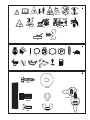
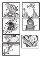
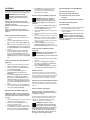
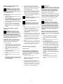
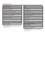
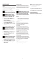
M10/30 HERITAGE TRACTOR CODE 134E INSTRUCTION BOOK CAUTION: Read and follow all instructions. Code 134E Serial No. 290000001 Issue 12/2009 Part No. 111-3047 (Rev D) 1742440 Revision D 1 1 2 3 MAX+ 90N MAX+ 150N 9 8 7 6 5 4 10 11 13 12 2 1 10 2 4 3 11 12 5 6 7 13 14 15 8 9 3 25x3 17x146 327349 1001054 17x47 2x82 14x79 3 3 4 5 8 1 4 7 (25x3) 2 5 6 (17x146) 4 (17x47) 1 1 5 (1001054) 3 2 6 1 7 6 6 (2x82) 3 2 4 1 6 6 (2x82) 8 4 5 4 7 (14x79) 5 3 7 9 2 8 9 1 8 9 7 10 1 B A 4 12 11 6 2 7 13 14 1 5 15 16 1 1 2 3 2 3 5 LIMITED WARRANTY Hayter Limited warrants to the original user / purchaser that this unit shall be free from defects in material and workmanship under normal use and service for a period of three years from the date of purchase. The manufacturer of the engine furnish their own warranty and services are provided through their authorised network (Refer to “Engine Warranty Statement”). To qualify for the full benefit of the warranty, the warranty registration card must be returned within 60 days of purchase. Subject to the conditions and exclusions noted in this limited warranty, we shall at our option, repair or replace any warranted part during the applicable period. If you are in doubt or experience any difficulty, please consult a Hayter Authorised Service Dealer for clarification. To qualify for the extended warranty (second and third year) of the three year limited warranty, the machine must have annual services carried out by an Authorised Hayter Service Dealer. These chargeable services should be carried out within 12 and 24 months of the date of purchase. Excluded from the extended warranty period are those items which are subject to normal wear and tear e.g. tyres, wheels, cutterblades, cables, batteries and other consumable wearing parts. All consumer machines which are fitted with a genuine Hayter friction disc as original equipment, before use, are covered by a Lifetime Warranty against the engine crankshaft bending. Note: friction washers, blade brake units and other such devices are not applicable. Only machines fitted with a genuine Hayter friction disc, which are used in accordance with the recommended operating and maintenance procedures, are covered. This warranty does not apply to any unit that has been tampered with, altered, misused, abused or used for hire, and will become invalid if non genuine Hayter parts are fitted. This warranty does not cover minor mechanical adjustments unless they are due to defective materials or workmanship. Consult the Owner’s Handbook or a Hayter Authorised Service Dealer for assistance when making these adjustments. A warranty period of 90 days applies to machines used for commercial purposes. To make a warranty claim, return the unit to a Hayter authorised dealer along with proof of purchase stating the machine serial number and date of purchase. The service receipt(s) or this Owner’s Handbook with the 1st/2nd year service boxes fully completed, must be produced as proof of entitlement to the extended warranty period. Subject to the conditions and exclusions in this limited warranty, the authorised dealer will, at our option, repair or replace any warranted part within the duration of the warranty period. This limited warranty gives you specific legal rights and is in addition to any statutory rights to which you may be entitled and your statutory rights are not affected by this warranty. If you need additional information concerning this written warranty, or assistance in obtaining services, please write to: HAYTER LIMITED, Service Department, Spellbrook, Bishop’s Stortford, Hertfordshire CM23 4BU. 1st Year Service Record 2nd Year Service Record Date . . . . . . . . . . . . . . . . . . . . . . . . . . . . . . . . . . . . . . . . . Signed . . . . . . . . . . . . . . . . . . . . . . . . . . . . . . . . . . . . . . . . Date . . . . . . . . . . . . . . . . . . . . . . . . . . . . . . . . . . . . . . . . . Signed . . . . . . . . . . . . . . . . . . . . . . . . . . . . . . . . . . . . . . . . 6 en CONTENTS LIMITED WARRANTY 6 15INTERNATIONAL PICTORIALS 7 OWNER’S INFORMATION 8 SAFE OPERATION PRACTICES 8 ASSEMBLY 9 OPERATION 8 MAINTENANCE CHART 10 MAINTENANCE 13 TROUBLESHOOTING CHART 15 INTERNATIONAL PICTORIALS IMPORTANT: The following pictorials are located on your unit or on literature supplied with the product. Before you operate the unit, learn and understand the purpose for each pictorial. NOTE: Illustrations and pictorials begin on page 2. Safety Warning Pictorials (Figure 1) 1 WARNING 2 IMPORTANT: Read Owner’s Manual Before Operating This Machine. 3 4 WARNING: Thrown Objects. Keep Bystanders Away. Read User Instructions Before Operating This Machine. 5 DANGER: Keep People, Especially Children, Away From Unit. Control And Operating Pictorials 6 DANGER: No Step. 1 Engine Start 7 DANGER: Keep Feet And Hands Away From Rotating Blade. 2 Lights 8 DANGER: Disconnect Spark Plug Wire Before Servicing Unit. 3 Engine Run 4 Engine Stop 9 WARNING: Hot Surface. 5 Engine Run 6 Brake 7 Parking Brake 8 Clutch 9 Slow 10 WARNING: Use Caution When Connecting Or Disconnecting Accessories. 11 WARNING: Crushed Fingers. 12 IMPORTANT: Follow Instructions In Owner’s Manual To Level The Deck. 13 WARNING: Stay Clear Of Mower Blade As Long As Engine Is Running. WARNING: Do Not Use This Machine On Slopes Greater Than 10 Degrees. (Figure 2) 10 Fast 11 Choke 12 Oil 13 Blade Rotation Control 14 Raise 15 Fuel 7 OWNER’S INFORMATION Know your product: If you understand the unit and how the unit operates, you will get the best performance. As you read this manual, compare the illustrations to the unit. Learn the location and the function of the controls. To help prevent an accident, follow the operating instructions and the safety rules. Save these original instructions for future reference. Preparation 1. 2. 3. WARNING: Look for this symbol to indicate important safety precautions. This symbol indicates: “Attention! Become Alert! Your Safety Is At Risk.” Responsibility Of The Owner WARNING: This cutting machine is capable of amputating hands and feet and throwing objects. Failure to observe the following safety instructions could result in serious injury or death to the operator or bystanders. 4. 5. The responsibility of the owner is to follow the instructions below. SAFE OPERATION PRACTICES For Ride-On (Riding) Rotary Mower Machines Training 1. 2. 3. 4. 5. 6. Read the instructions carefully. Be familiar with the controls and the proper use of the equipment. Never allow children or people unfamiliar with these instructions to use the mower. Local regulations may restrict the age of the operator. Never mow while people, especially children, or pets are nearby. Keep in mind that the operator or user is responsible for accidents or hazards occurring to other people or their property. Do not carry passengers. All drivers should seek and obtain professional and practical instruction. Such instruction should emphasize: a. the need for care and concentration when working with ride-on machines; b. control of a ride-on machine sliding on a slope will not be regained by the application of the brake. The main reasons for loss of control are: • insufficient wheel grip; • being driven too fast; • inadequate braking; • the type of machine is unsuitable for its task; • lack of awareness of the effect of ground conditions, especially slopes; • incorrect hitching and load distribution. 6. 8. While mowing, always wear substantial footwear and long trousers. Do not operate the equipment when barefoot or wearing open sandals. Thoroughly inspect the area where the equipment is to be used and remove all objects which may be thrown by the machine. WARNING - Petrol is highly flammable. a. Store fuel in containers specifically designed for this purpose. b. Refuel outdoors only and do not smoke while refuelling. c. Add fuel before starting the engine. Never remove the cap of the fuel tank or add petrol while the engine is running or when the engine is hot. d. If petrol is spilled, do not attempt to start the engine but move the machine away from the area of spillage and avoid creating any source of ignition until petrol vapours have dissipated. e. Replace all fuel tanks and container caps securely. Replace faulty silencers. Before using, always visually inspect to see that the blades, blade bolts and cutter assembly are not worn or damaged. Replace worn or damaged blades and bolts in sets to preserve balance. On multi-blade machines, take care as rotating one blade can cause other blades to rotate. 2. 3. 4. 5. 6. 7. 10. 11. 12. 13. 14. 15. Operation 1. 9. Do not operate the engine in a confined space where dangerous carbon monoxide fumes can collect. Mow only in daylight or in good artificial light. Before attempting to start the engine, disengage all blade attachment clutches and shift into neutral. Do not use on slopes of more than 10 degrees. Remember there is no such thing as a “safe” slope. Travel on grass slopes requires particular care. To guard against overturning: a. do not stop or start suddenly when going up or downhill; b. engage clutch slowly, always keep machine in gear, especially when travelling downhill; c. machine speeds should be kept low on slopes and during tight turns; d. stay alert for humps and hollows and other hidden hazards; e. never mow across the face of the slope, unless the mower is designed for this purpose. Use care when pulling loads or using heavy equipment. a. Use only approved drawbar hitch points. b. Limit loads to those you can safely control. c. Do not turn sharply. Use care when reversing. d. Use counterweight(s) or wheel weights when suggested in the Instruction Book. Watch out for traffic when crossing or near roadways. 8 16. 17. 18. Stop the blades rotating before crossing surfaces other than grass. When using any attachments, never direct discharge of material toward bystanders nor allow anyone near the machine while in operation. Never operate the mower with defective guards or shields, or without safety protective devices in place. Do not change the engine governor settings or overspeed the engine. Operating an engine at excessive speed may increase the hazard of personal injury. Before leaving the operator’s position a. disengage the power take-off and lower the attachments; b. change into neutral and set the parking brake; c. stop the engine and remove the key. Disengage drive to attachments, stop the engine, and disconnect the spark plug wire(s) or remove the ignition key a. before cleaning blockages or unclogging chute; b. before checking, cleaning or working on the mower; c. after striking a foreign object. Inspect the mower for damage and make repairs before restarting and operating the equipment; d. if the machine starts to vibrate abnormally (check immediately). Disengage drive to attachments when transporting or not in use. Stop the engine and disengage drive to attachment a. before refuelling; b. before removing the grass catcher; c. before making height adjustment unless adjustment can be made from the operator’s position. Reduce the throttle setting during engine run-out and, if the engine is provided with a shut-off valve, turn the fuel off at the conclusion of mowing. Before and when backing, look behind and down for small children. Use extra care when approaching blind corners, shrubs, trees or other objects that may obscure vision. Maintenance and Storage 1. 2. 3. 4. 5. 6. 7. 8. 9. On multi-blade machines, take care as rotating one blade can cause other blades to rotate. When machine is to be parked, stored or left unattended, lower the cutting means unless a positive mechanical lock is used. Keep all nuts, bolts, and screws tight to be sure the equipment is in safe working condition. Never store the equipment with petrol in the tank inside a building where fumes may reach an open flame or spark. Allow the engine to cool before storing in any enclosure. To reduce the fire hazard, keep the engine, silencer, battery compartment and petrol storage area free of grass, leaves, or excessive grease. Check the grass catcher frequently for wear or deterioration. Replace worn or damaged parts for safety. If the fuel tank has to be drained, this should be done outdoors. ASSEMBLY 4. All fasteners are in the parts bag. Do not discard any parts or material until the unit is assembled. WARNING: Before doing any assembly or maintenance to the mower, remove the wire from the spark plug. NOTE: In this instruction book, left and right describe the location of a part with the operator on the seat. NOTE: Illustrations and pictorials begin on page 2. NOTE: To assemble the following loose parts, use the fasteners shown at full size in Figure 3. How To Install The Seat (Figure 4) 1. 2. 3. 4. Carefully remove the plastic bag from the seat (1). Raise the seat support (2) and secure in the UP position with the seat support rod (6). Align the holes in the seat (1) to the holes in the seat support (2). Fasten the seat (1) to the seat support (2) with the fasteners (4) and (5). Check the operating position of the seat (1). If the seat (1) needs to be adjusted, loosen the two wing bolts (5). Slide the seat (1) forward or backward along the seat adjusting holes (3). Tighten the wing bolts (5). How To Charge The Battery (Figure 6) WARNING: When you charge the battery, do not smoke. Keep the battery away from any sparks. The fumes from the battery acid can cause an explosion. 1. 2. 3. 4. 5. WARNING: To prevent sparks, fasten the red cable to the positive (+) terminal before you connect the black cable. How To Assemble The Steering Wheel (Figure 5) 2. 1. 2. 3. 3. 4. 5. To disconnect the battery retainer (2) from the battery tray (3), push in on the lower end of the battery retainer (2). Remove the battery (1) from the right side of the unit. Remove the protective cap from the battery terminal. Use a 12 volt battery charger to charge the battery (1). Charge at a rate of 6 amperes for one hour. If you do not have a battery charger, have an authorized service centre charge the battery. Install the battery (1) and secure with the battery retainer (2). Make sure the positive (+) terminal (4) is on the right side. How To Install The Battery Cables (Figure 6) 1. Make sure the front wheels point forward. Slide the tube (1) into the console (2). Make sure the end of the tube (1) fits over the steering bushing (3). Attach the steering wheel (4) to the steering post (5) with screw (7) and washer (6). Slide the steering wheel (4) and steering post (5) into the tube (1) and console (2). Push on the steering wheel (4). The steering post (5) will lock onto the pinion gear. Pull on the steering wheel (4). Make sure that the steering post (5) is locked in place. Some models have an optional insert (8) in the parts bag. Attach the insert (8) to the centre of the steering wheel (4). If the battery (1) is put into service after the battery date, the battery (1) must be charged. See “How To Charge The Maintenance Free Battery”. Remove the protective cap from the battery terminal. Fasten the red cable (5) and terminal cover (9) to the positive (+) terminal (4) with the fasteners (6) and (7). Fasten the black cable (8) to the negative (-) terminal with the fasteners (6) and (7). Check The Tires Check the air pressure in the tires. Tires with too much air pressure will cause the unit to ride rough. Also, the wrong air pressure will keep the mower housing from cutting level. The correct air pressure is shown on the side of the tire. Check The Level Of The Mower Housing Make sure the level of cut is still correct. After you mow a short distance, look at the area that was cut. How To Prepare The Engine Maintenance Free Battery (Figure 6) IMPORTANT: Before you attach the battery cables to the battery, check the battery date. The battery date tells if the battery must be charged. 1. 2. 3. Raise the seat support and secure in the UP position with the seat support rod. Check the top of the battery (1) for the location of the battery date. If the battery (1) is put into service before the battery date, the battery cables can be attached without charging the battery (1). See “How To Install The Battery Cables”. NOTE: The engine was shipped from the factory filled with oil. Check the level of the oil. Add oil as needed. See the engine manufacturer’s instructions for the type of petrol and oil to use. Before you use the unit, read the information on safety, operation, maintenance, and storage. WARNING: Follow the engine manufacturer’s instructions for the type of petrol and oil to use. Always use a safety petrol container. Do not smoke when adding petrol to the engine. When inside an enclosure, do not fill with petrol. Before you add petrol, stop the engine. Let the engine cool for several minutes. 9 Important! Before You Start Mowing T T T Check the engine oil. T T Check the air pressure of the tyres. Fill the fuel tank with petrol. Check the level of the mower housing. Attach the battery cables. Final Assembly 1. 2. Check all fasteners. Make sure all fasteners are properly installed and are tight. Check installation. Make sure all parts are correctly installed. WARNING: Make sure that the grass bagger is properly assembled and correctly installed. The Grass Bagger must only be used when fully assembled and correctly installed. OPERATION 3. NOTE: Illustrations and pictorials begin on page 2. Location Of Controls (Figure 7) Blade Rotation Control (1): Use the blade rotation control to start and stop the rotation of the blade. Clutch / Brake Pedal (2): The pedal has two functions. The first function is a clutch. The second function is a brake. Ignition Switch (3): Use the ignition switch to start and stop the engine. Speed Control Lever (4): The speed and direction of travel is controlled by the speed control lever. Use the speed control lever to select either forward or reverse. Lift Lever (5): Use the lift lever to change the height of cut. Parking Brake Lever (6): Use the parking brake lever to engage the brake when you leave the unit. Throttle Control Lever (7): Use the throttle control lever to increase or decrease the speed of the engine. Attachments This unit can use many different attachments. This unit can pull attachments like a lawn sweeper, a lawn aerator, or a hopper spreader. This unit can not use attachments that engage the ground like a plough, a disk harrow, or a cultivator. 4. To stop the blade, move the blade rotation control (1) to the DISENGAGE position (8). Before you leave the operator’s position, make sure the blade(s) has stopped rotating. Before you ride the unit across a sidewalk or a road, move the blade rotation control (1) to the DISENGAGE position. WARNING: Always keep your hands and feet away from the blade, deflector opening, and the mower housing when the engine runs. How To Engage The Transmission To allow the unit to be pushed, it was shipped with the automatic drive disconnect in the PUSH position (A, Figure 10). Before operating, the automatic drive disconnect must be set in the DRIVE position (B, Figure 10). 1. The engine must be off. 2. The automatic drive disconnect is located under the left side of the seat deck, next to the hydrostatic transaxle. 3. To engage the transmission, unlatch the automatic drive disconnect. The transmission is now connected and ready to operate. 4. To release the transmission and push the unit, pull and twist the automatic drive disconnect. Latch the automatic drive disconnect in the PUSH position (A, Figure 10). The transmission is now released and the unit can be pushed. How To Use The Parking Brake (Figure 10) 1. 2. 3. 4. WARNING: Before you leave the operator’s position, move the shift lever to the neutral (N) position. Set the parking brake. Move the blade rotation control to the DISENGAGE position. Stop the engine and remove the ignition key. How To Change The Cutting Height (Figure 14) To change the cutting height, raise or lower the lift lever (5) as follows. 1. Move the lift lever (5) forward to lower the mower housing and back to raise the mower housing. 2. When you ride on a sidewalk or road, move the lift lever (5) to the highest position and move the blade rotation control (1) to the DISENGAGE position. How To Stop The Unit (Figure 7) 1. NOTE: In cold weather, the heavy viscosity oil in the transmission will make the unit difficult to push. 2. For trailer and pull-behind attachments, the maximum weight is 90 kg (200 lbs). How To Use The Speed Control Lever 3. Do not operate on a slope that is greater than 10 degrees when using a pull-behind attachment or trailer. The Hydrostatic Drive is very easy to operate. The drive system has a clutch/brake pedal on the left side (Figure 11) and a speed control lever on the right side (Figure 13). 4. How To Use The Throttle Control (Figure 7 and Figure 8) Use the throttle/choke control (7) to increase or decrease the speed of the engine. 1. Move the throttle/choke control (7) completely forward to the CHOKE position to start a cold engine. 2. The FAST position is marked with a detent. For normal operation and when using a grass bagger, move the throttle control to the FAST position. For maximum charging of the battery and for a cooler running engine, operate the engine in the FAST position. 3. The engine governor is set at the factory for maximum performance. Do not adjust the governor to increase the speed of the engine. How To Use The Blade Rotation Control (Figure 7 and Figure 9) Use the blade rotation control (1) to engage the blade(s). 1. Before you start the engine, make sure the blade rotation control (1) is in the DISENGAGE position (8). 2. To rotate the blade, move the blade rotation control (1) forward to lock the blade in the ENGAGE position (9). To Drive Forward: 1. The automatic drive disconnect must be in the DRIVE position (B, Figure 10). 2. Completely push the clutch/brake pedal forward to stop the unit (see Figure 11). Keep your foot on the pedal. 3. Move the speed control lever to the NEUTRAL position (see Figure 13). 4. Slowly release your foot from the clutch/brake pedal (see Figure 11). Do not keep your foot on the pedal. 5. Move the throttle control to the FAST position (see Figure 12). 6. Slowly push the speed control lever forward to the desired speed (see Figure 10). To reduce forward speed, slowly pull the speed control lever to the desired speed. To Drive in Reverse: 1. Always disengage blades and look down and behind before and while backing. 2. Move the speed control lever to the NEUTRAL position (see Figure 13). 3. To go backward, move the speed control lever to the REVERSE position. 10 Completely push the clutch/brake pedal (2) forward. Lift the parking brake lever (6). Remove your foot from the clutch/brake pedal (2) and then release the parking brake lever (6). Make sure the parking brake will hold the unit. To release the parking brake (6), completely push the clutch/brake pedal (2) forward. The parking brake will automatically release. Completely push the clutch/brake pedal (2) forward to stop the unit. Keep your foot on the pedal. Move the blade rotation control (1) to the DISENGAGE position. Move the shift lever (4) to the NEUTRAL position. Set the parking brake (6). WARNING: Make sure the parking brake will hold the unit. 5. 6. Move the throttle control (7) to the SLOW position. To stop the engine, turn the ignition key (3) to the OFF position. Remove the key. How To Transport The Unit To transport the unit, follow the steps below. 1. Move the blade rotation control to the DISENGAGE position. 2. Raise the lift lever to the highest position. 3. Move the throttle control to a position between SLOW and FAST. 4. To go faster, move the shift lever to a faster speed. How To Install The Side Discharge Attachment (Figure 15) 7. 8. WARNING: To prevent the engine from starting, disconnect the wire from the spark plug. Make sure the attachment clutch/blade rotation control is in the DISENGAGE position. 9. The mulcher cover (1) lets you mulch the grass for a clean, fine cut. 1. Remove the two nuts (3) that secure the mulcher cover (1). 2. Lift the mulcher cover (1). Mount the side discharge attachment (2) onto the same bolts that secured the mulcher cover (1). 3. Secure the side discharge attachment (2) with the nuts (3). 4. To mulch, remove the side discharge attachment (2) and mount the mulcher cover (1) to the mower housing with the nuts (3). How To Operate With The Mower Housing WARNING: The mulch cover is a safety device. Do not remove the mulch cover. The deflector forces the discharged material toward the ground. Always keep the deflector in the down position. If the deflector is damaged, replace the deflector with an original equipment part from an authorized service centre. IMPORTANT: When you operate with the mower housing, always operate with the throttle control in the FAST position. 1. 2. 3. 4. 5. 6. Start the engine. Move the lift lever to a height of cut position. In high or thick grass, cut the grass in the highest position first and then lower the mower housing to a lower position. Move the throttle control to the SLOW position. Slowly move the blade rotation control to the ENGAGE position. Push the clutch/brake pedal completely forward. Move the shift lever to one of the speed settings. NOTE: When you mow in heavy grass or mow with a bagger, put the shift lever in the slowest speed. Slowly release the clutch/brake pedal. Move the throttle control to the FAST position. If you need to go faster or slower, stop the unit and move the shift lever to another speed setting. Make sure the level of cut is still correct. After you mow a short distance, look at the area that was cut. If the mower housing does not cut level, see the instructions on “How To Level The Mower Housing” in the Maintenance section. WARNING: For better control of the unit, select a safe speed. How To Operate On Hills WARNING: Do not ride up or down slopes that are too steep to back straight up. Never ride the unit across a slope. 1. 2. 3. 4. 5. Before you ride up or down a hill, move the shift lever to the slowest speed. Do not stop or change speed settings on a hill. If you must stop, quickly push the clutch/brake pedal forward and set the parking brake. To start again, make sure the shift lever is in the slowest speed. Move the throttle control to the SLOW position. Slowly release the pedal. If you must stop or start on a hill, always have enough space for the unit to roll when you release the brake and engage the clutch. Be very careful when you change directions on a hill. When on a slope or in a turn on a hill, move the throttle control to the SLOW position to help prevent an accident. Before Starting The Engine Add Petrol WARNING: Always use a safety petrol container. Do not smoke when adding petrol to the fuel tank. Do not add petrol when you are inside an enclosure. Before you add petrol, stop the engine and let the engine cool for several minutes. (Figure 16) Fill the fuel tank (1) to the FULL (2) position with regular unleaded petrol. Do not use premium unleaded petrol. Make sure the petrol is fresh and clean. Leaded petrol will increase deposits and shorten the life of the valves. How To Start The Engine WARNING: The electrical system has an operator presence system that includes a sensor switch for the seat. These components tell the electrical system if the operator is sitting on the seat. This system will stop the engine when the operator leaves the seat. For your protection, always make sure this system operates correctly. NOTE: The engine will not start unless you depress the clutch/brake pedal and move the blade rotation control to the DISENGAGE position. 1. 2. 3. 4. 5. NOTE: If the engine does not start after four or five tries, move the throttle control to the FAST position. Again try to start the engine. If the engine will not start, see the TROUBLE SHOOTING CHART. Check The Oil NOTE: The engine was shipped from the factory filled with oil. Check the level of the oil. Add oil as needed. See the engine manufacturer’s instructions for the type of petrol and oil to use. 1. Make sure the unit is level. NOTE: Do not check the level of the oil while the engine runs. 2. 3. Check the oil. Follow the procedure in the engine manufacturer’s instructions. If necessary, add oil until the oil reaches the FULL mark on the dipstick. The quantity of oil needed from ADD to FULL is shown on the dipstick. Do not add too much oil. 11 Push the clutch/brake pedal completely forward. Keep your foot on the pedal. Move the shift lever to the neutral (N) position. Make sure the blade rotation control is in the DISENGAGE position. Move the throttle control completely forward to the CHOKE or FAST position. Some models have a separate choke knob. Pull the choke knob to the full CHOKE position. Turn the ignition key to the START position. 6. 7. Slowly move the throttle control to the SLOW position. To start a hot engine, move the throttle control to a position between FAST and SLOW. Mowing And Bagging Tips 1. 2. 3. 4. 5. 6. 7. For a lawn to look better, check the cutting level of the mower housing. For the mower housing to cut level, make sure the tyres have the correct amount of air pressure. Every time you use the unit, check the blade. If the blade is bent or damaged, immediately replace the blade. Also, make sure the nut for the blade is tight. Keep the blade(s) sharpened. Worn blades will cause the ends of the grass to turn brown. Do not cut or bag grass that is wet. Wet grass will not discharge correctly. Let the grass dry before cutting. Use the left side of the mower housing to trim near an object. Discharge the cut grass onto the mowed area. The result is a more even discharge of cut grass. Mulching Tips 8. 9. 10. 11. 12. 13. When you mow large areas, start by turning to the right so that the cut grass will discharge away from shrubs, fences, driveways, etc. After one or two rounds, mow in the opposite direction making left turns until finished. If the grass is very high, cut two times to decrease the load on the engine. First cut with the mower housing in the highest position and then lower the mower housing for the second cut. For better engine performance and an even discharge of the cut grass, always operate the engine with the throttle in FAST position. When you use a bagger, operate the engine with the throttle in FAST position and the shift lever in first or second gear. For better cutting performance and a quality cut, mow with the shift lever in one of the slower speeds. After each use, clean the bottom and top of the mower housing for better performance. Also, a clean mower housing will help prevent a fire. 12 When you use a mulcher attachment, the grass is cut into very small pieces. These small pieces will quickly break down. Because the nutrients are returned to the soil, the lawn will need less fertilizer. To correctly mulch the grass, follow the steps below. 1. Set the throttle in the FAST position. Operate the mower at a slower ground speed. If ground speed is too fast, the grass will not have an even cut. 2. Keep a sharp edge on the blade. A blade that is not sharp will cause the ends of the grass to become brown. 3. Make sure the grass is dry. Wet grass is difficult to cut. 4. Set the height of the mower housing so that only the top third of the grass is cut. If the grass is too high, set the height of the mower housing to the maximum height. Then, lower the mower housing for the second cut. Also, instead of using the full width of the mower housing, mulch at half the width. 5. Clean the bottom of the mower housing. Grass and other debris can keep the mower from working correctly. 6. If the grass grows fast, mulch more often. 7. If an area needs improvement, mulch a second time. MAINTENANCE CHART TRACTOR AND MOWER ENGINE Every 8 Hours or Daily First 5 Hours Check safety interlock system Change engine oil Clean debris oŮ tractor and mower deck Every 8 Hours or Daily Clean debris from engine compartment Check engine oil level Every 25 Hours or Annually * Every 25 Hours or Annually * Check tire pressure Clean engine air lter and pre-cleaner ** Check mower blade stopping time Every 50 Hours or Annually * Check tractor and mower for loose hardware Change engine oil Replace oil lter Every 50 Hours or Annually * Clean battery and cables Annually Check tractor brakes Replace air lter Replace pre-cleaner See Dealer Annually to Lubricate tractor and mower See Dealer Annually to Inspect muűer and spark arrester Replace spark plug Check mower blades ** * Whichever comes rst ** Check blades more often in regions with sandy soils or high dust conditions. Replace fuel lter Clean engine air cooling system * Whichever comes rst ** Clean more often in dusty conditions or when airborne debris is present. 13 MAINTENANCE Check the Tires NOTE: Illustrations and pictorials begin on page 2. How To Remove The Battery (Figure 6) Check the air pressure in the tires. Tires with too much air pressure will cause the unit to ride rough. Also, the wrong air pressure will keep the mower housing from cutting level. The correct air pressure is shown on the side of the tire. To charge or clean the battery (1), remove the battery (1) from the unit as follows. Storage Before starting the unit after it has been stored: O O O WARNING: To prevent sparks, disconnect the black battery cable (8) from the negative (-) terminal before you disconnect the red cable (5). WARNING: The battery contains sulphuric acid which is harmful to the skin, eyes and clothing. If the acid gets on the body or clothing, wash with water. 1. 2. 3. 4. Disconnect the black cable (8) from the negative (-) terminal. Disconnect the red cable (5) from the positive (+) terminal (4). To disconnect the battery retainer (2) from the battery tray (3), push in on the lower end of the battery retainer (2). Remove the battery (1) from the right side of the unit. WARNING: Never store the unit (with fuel) in an enclosed, ventilated structure. Fuel vapors can travel to an ignition source (such as a furnace, water heater, etc.) and cause an explosion. Fuel vapor is also toxic to humans and animals. When Storing Fuel Or Equipment With Fuel In Tank O Store away from furnaces, stoves, water heaters or appliances that have pilot lights or other ignition sources because they can ignite fuel vapors. Equipment Battery life will be increased if it is removed. Put in a cool, dry place and fully charged about once a month. If the battery is left in the unit, disconnect the negative cable. How To Charge The Battery (Figure 6) Fuel System WARNING: When you charge the battery, do not smoke. Keep the battery away from any sparks. The fumes from the battery acid can cause an explosion. Fuel can become stale when stored over 30 days. Stale fuel causes acid and gum deposits to form in the fuel system or on essential carburetor parts. To keep fuel fresh, use Briggs & Stratton FUEL FIT® fuel stabilizer, available as a liquid additive or a drip concentrate cartridge. There is no need to drain gasoline from the engine if a fuel stabilizer is added according to instructions. Run the engine for 2 minutes to circulate the stabilizer throughout the fuel system. The engine and fuel can then be stored up to 24 months. If gasoline in the engine has not been treated with a fuel stabilizer, it must be drained into an approved container. Run the engine until it stops from lack of fuel. The use of a fuel stabilizer in the storage container is recommended to maintain freshness. 1. 2. 3. Before you charge the battery (1), remove the battery (1). To charge the battery (1), use a 12 volt battery charger. Charge at a rate of 6 amperes for 1 hour. Install the battery (1). WARNING: To prevent sparks, fasten the red cable to the positive (+) terminal before you connect the black cable. 4. 5. 6. Fasten the red cable (5) to the positive (+) terminal (4) with the fasteners as shown. Fasten the black cable (8) to the negative (-) terminal with the fasteners as shown. Connect the battery retainer (2) to the battery tray (3). Engine Oil While the engine is still warm, change the engine oil. See the Engine Manual. 14 Check all fluid levels. Check all maintenance items. Perform all recommended checks and procedures found in this manual. Allow the engine to warm up for several minutes before use. Order Replacement Parts Warranty service is available only through Authorized Service Dealers. Locate your nearest dealer in our locator map at www.murray.com. TROUBLESHOOTING CHART Troubleshooting the Tractor PROBLEM LOOK FOR Brake pedal not depressed. REMEDY Fully depress brake pedal. PTO (electric clutch) switch is in Place in OFF position. ON position. Cruise control engaged. Move knob to NEUTRAL/OFF position. Out of fuel. If engine is hot, allow it to cool, then refill the fuel tank. Engine flooded. Disengage the choke. Fuse is blown. Engine will not turnover Battery terminals require or start. cleaning. See authorized dealer. See Cleaning the Battery and Cables section. Battery discharged or dead. Recharge or replace battery. Wiring loose or broken. Visually check wiring. If wires are frayed or broken, see authorized dealer. Solenoid or starter motor faulty. See authorized dealer. Engine starts hard or runs poorly. Engine knocks. Excessive oil consumption. Engine exhaust is black. Safety interlock switch faulty. See authorized dealer. Water in fuel. See authorized dealer. Gas is old or stale. See authorized dealer. Fuel mixture too rich. Clean air filter. Engine has other problem. See authorized dealer. Low oil level. Check/add oil as required. Using wrong grade oil. See Engine Manual. Engine running too hot. See authorized dealer. Using wrong grade oil. See Engine Manual. Too much oil in crankcase. Drain excess oil. Dirty air filter. See Engine Manual. Choke closed. Open choke. Ground speed control pedals not depressed. Depress pedals. Transmission release lever in PUSH position. Move into DRIVE position. Engine runs, but tractor Mower drive belt is broken. will not drive. Parking brake is engaged. Brake will not hold. Tractor steers hard or handles poorly. See authorized dealer. Disengage parking brake. Traction drive belt is broken or slipping. See authorized dealer. Internal brake worn. See authorized dealer. Steering linkage is loose. See authorized dealer. Improper tire inflation. See Check Tire Pressure section. Front wheel spindle bearings dry. See authorized dealer. 15 Troubleshooting the Mower PROBLEM Mower will not raise. Mower cut is uneven. Mower cut is rough looking. Engine stalls easily with mower engaged. LOOK FOR Lift linkage not properly attached or damaged. See authorized dealer. REMEDY Mower not leveled properly. See authorized dealer. Tractor tires not properly inflated. See Check Tire Pressure section. Engine speed too slow. Set to full throttle. Ground speed too fast. Slow down. Mower has other problem. See authorized dealer. Engine speed too slow. Set to full throttle. Ground speed to fast. Slow down. Dirty or clogged air filter. See Servicing Air Filter section. Cutting height set too low. Cut tall grass at maximum cutting height during first pass. Discharge chute jamming. Cut grass with discharge pointing toward previously cut area. Engine not up to operating temperature. Run engine for several minutes to warm-up. Excessive mower vibration. Starting mower in tall grass. Start the mower in a cleared area. Mower has other problem. See authorized dealer. Engine runs and tractor Blade rotation control not engaged. drives, but mower will Mower has other problem. not drive. Engage blade rotation control. See authorized dealer. 16