1
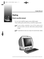
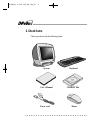
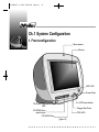
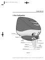
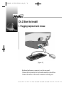
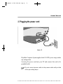
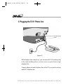
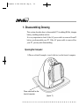
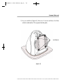
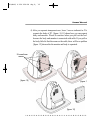
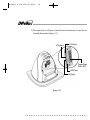
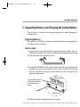
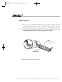
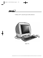
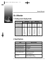
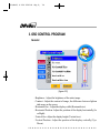
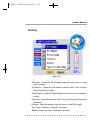
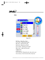
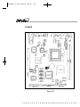
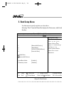
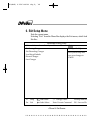
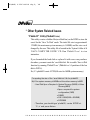
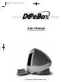
AIO(DAE) 0.3.30 3:39 PM ∆‰¿Ã¡ˆ1
User’s Manual
DAEWOO TELECOM LTD.
AIO(DAE) 0.3.30 3:39 PM ∆‰¿Ã¡ˆ2
CONTENTS
Starting
3
1. How to use this manual
3
2. Check Items
4
3. System Setting
5
Ch1.System Configuration
6
1. Front configuration
6
2. Rear configuration
7
Ch2. Start to Install
8
1. Plugging the mouse/keyboard
8
2. Plugging the Power Cord
9
3. Plugging the RJ11 Phone line
10
Ch3. System Disassembling & assembling
11
1. Disassemble Drawing
12
2. Upgrading Memory and Replacing Backup Battery
17
3. Assemble Drawing
20
Ch4.Monitor
23
1. Factory Preset Display Mode
23
2. Technical Specification
23
3. OSD Program Description
24
Ch5.Mother Board
28
1. Specification
28
2. Layout
30
3. Set Jumper
31
Ch6.Bios setup
32
AIO(DAE) 0.3.30 3:39 PM ∆‰¿Ã¡ˆ3
Daewoo Telecom Lt
Starting
How to use this manual
It is very easy to install the computer system with this manual.
Please read this guide carefully, before you install the computer system.
For your safety, remember to turn off the system and to
disconnect all the cords and cables before opening the system
chassis.
To avoid electric shock, do not open the monitor frame chassis.
[figure. 1]
AIO(DAE) 0.3.30 3:39 PM ∆‰¿Ã¡ˆ4
2.Check Items
Check your boxes for the following items.
System
Keyboard
User’s Manual
CD-ROM Title
Power cord
Mouse
AIO(DAE) 0.3.30 3:39 PM ∆‰¿Ã¡ˆ5
Daewoo Telecom Lt
3.System Setting
Operate the PC on a sturdy level surface such as desk or table.
Please do not overload the power
socket.
Place the system away from high
temperature and direct sunlight.
Do not place magnetic objects close
to the system.
Keep distance between the system
and the wall.
Avoid dust or moisture from the
system.
Place the system away from radio or
any electronic receivers.
AIO(DAE) 0.3.30 3:39 PM ∆‰¿Ã¡ˆ6
Ch.1 System Configuration
1.Front configuration
Micro-phone
Monitor
HDD LED
Power Butto
FDD eject button
CD-ROM Drive
LED
Floppy Disk Drive
CD-ROM Drive
eject button
FDD LED
CD-ROM Drive
[figure.2]
AIO(DAE) 0.3.30 3:39 PM ∆‰¿Ã¡ˆ7
Daewoo Telecom Lt
2.Rear Configuration
AC Power
Speaker
Phone
Mouse
Keyboard
Tel Line(to the
Serial port
Parallel port
MIDI/Game port
[figure.3]
LAN
USB port
Speaker out
Line in
AIO(DAE) 0.3.30 3:39 PM ∆‰¿Ã¡ˆ8
Ch.2 Start to Install
1.Plugging keyboard and mouse
[figure. 4]
Keyboard and mouse connector is on the rear panel.
Connect the keyboard to the keyboard connector colored blue.
Connect the mouse to the mouse connector colored green.
AIO(DAE) 0.3.30 3:39 PM ∆‰¿Ã¡ˆ9
Daewoo Telecom Lt
2.Plugging the power cord
[figure. 5]
D@eBox Computer System applies both 110/220V power range withou
any setting action.
Just plug the power cord into your PC and connect the cord to th
grounded outlet.
Do not connect power cable to the power outlet until you finish
all the preceding steps.
AIO(DAE) 0.3.30 3:39 PM ∆‰¿Ã¡ˆ10
3.Plugging the RJ11 Phone line
Tel Line(to the wa
Phone
[figure. 6]
With telephone line connectivity, you can network PCs located anywher
in the same building where you have access to jacks from a singl
telephone line.
Connect phone jack and telephone line of the PCs you want to networ
with RJ11 telephone line.
AIO(DAE) 0.3.30 3:39 PM ∆‰¿Ã¡ˆ11
Daewoo Telecom L
CH3. System disassemble & assemble
This model provides many convenient options that gives you more syste
flexibility. This chapter describes how to install optional part inside th
computer and remove and replace the computer cover and expansion-ca
cage.
Are you ready?
For easier work with inside your computer , please check out you hav
proper lighting and a clean work space. If you temporarily disconne
cables or remove expansion cards, make sure you note the position of th
connectors and slots so that you can reassemble the system correctly.
Rules for safety
1. Remove all the AC power source from your computer and a
peripherals.
2. Connection any telephone or telecommunication lines from th
computer may cause personal injury or electric shock.
3. Please wait 5 seconds after turning off the computer befo
disconnecting the peripheral or removing the component when you a
disconnecting a peripheral from the computer or removing a compone
from the system board, to avoid possible damage to the system board.
4. Touch an unpainted metal surface on the computer chassis, such as th
power supply, before touching anything inside your computer.
To avoid static electricity that might harm internal components, plea
touch an unpainted metal surface on the computer chassis periodicall
Touching components or contacts on a card or pins on a chip might cau
damage of components.
AIO(DAE) 0.3.30 3:39 PM ∆‰¿Ã¡ˆ12
1. Disassembling Drawing
This section describes how to disassemble PC for adding RAMs, changin
battery, installing modem card etc.
It is very important to check if the AC power cable is removed from PC
before you disassemble your PC. If the AC power cable is removed form
your PC, you may start disassembling.
Opening the Computer
1) Place a soft stuff (example : towel, cloth etc.) on the front of computer.
Place a soft stuff on the
front of computer
[figure. 7]
AIO(DAE) 0.3.30 3:39 PM ∆‰¿Ã¡ˆ13
Daewoo Telecom Lt
2) As you could see [figure.8], there are 5 screws and loose 4 of them
which is indicated as ① to separate the thin plate.
① Loose these sc
[figure. 8]
AIO(DAE) 0.3.30 3:39 PM ∆‰¿Ã¡ˆ14
3) After you separate the thin plate as you can see in [figure. 9], loose
screws indicated as ➁ to separate transparent case ➂, first remove th
speaker cable (➃) which is connected to speaker at this moment.
➁ loose these
➂ transparent cose
➃ remove the speaker
cable
[figure. 9]
AIO(DAE) 0.3.30 3:39 PM ∆‰¿Ã¡ˆ15
Daewoo Telecom Lt
4) After you separate transparent case, loose 3 screws indicated as ⑤ to
separate the body of PC. [figure. 10,11] shows how you can separat
body and monitor. Please be cautious when you pull out the bod
because the body and monitor is connected with cable. If you pull ou
the body little bit first then remove the cable, there will be no problem
[figure. 12] shows after the monitor and body is separated.
⑤ Loose these
screws
[figure. 10]
[figure. 11
[figure. 12]
AIO(DAE) 0.3.30 3:39 PM ∆‰¿Ã¡ˆ16
5) Description for each part of main board and interface board locate
beneath the monitor.[figure. 13]
VGA(9pin)
VGA(6pin)
Power(24pin)
(M/B, HDD,
LED(7pin)
Mic(2pin)
[figure. 13]
AIO(DAE) 0.3.30 3:39 PM ∆‰¿Ã¡ˆ17
Daewoo Telecom Lt
2. Upgrading Memory and Changing the backup Battery
This section is to describe that upgrading memory and Changing th
backup battery.
Upgrading Memory
This model has 64 Mbytes memory as a default and you can upgrade ma
256 Mbytes when you need.
How to install
1) Locate the two clips that hold the memory module in place. One cli
holds the left edge of the module and the other clip holds the right edge
2) Push both clips away from the socket.
3) Position the DIMM over the socket so that the notch at the bottom of th
module lines up over the divider in the socket. As shown in the nex
picture, match the wide part of the module to the wide part of th
opening in the socket.
To insert DIMM module :
Position botton notches
over socket dividers
shown
DIMM
Memory module
notches
DIMM Socket
4) Push the module straight down into the socket.
AIO(DAE) 0.3.30 3:39 PM ∆‰¿Ã¡ˆ18
How to remove
1) Locate the two clips that hold the memory module in place. One cli
holds the left edge of the module and the other clip holds the right edge
2) Push one clip away from the module. Then, while holding the modul
with one hand, push the other clip away from the module.
DIMM
Memory module
DIMM Socket
3) Lift the module out of the socket.
AIO(DAE) 0.3.30 3:39 PM ∆‰¿Ã¡ˆ19
Daewoo Telecom Lt
Changing the Battery
1) A mercury cell is located in the center of main board to keep setup dat
of CMOS
2) If you see the case part, you could find protruding part(➁). Kee
pushing this protruding part and remove existing cell then install new
cell. If you are using metallic driver to push, try not to touch any othe
part with the metallic tool.
There is the danger of an explosion if the battery is incorrectl
replaced.
Replace th e battery with the sa me or equivalent ty pe
recommended by the manufacturer.
Discard used batteries according to the battery manufacturer’s
instructions.
➁
Side battery to this side.
push this
[figure. 14]
AIO(DAE) 0.3.30 3:39 PM ∆‰¿Ã¡ˆ20
3. Assembling Drawing
1) You can assemble PC with reverse order of disassembling. First of al
please check if all part is attached firmly.
2) Connect body and monitor with cable.
3) Put in PC body after fitting ① and ➁.(FDD,CDROM is front)[figure. 15
4) Drive these screw. [figure. 16]
①
➁
➂
[figure. 15]
[figure. 16]
AIO(DAE) 0.3.30 3:39 PM ∆‰¿Ã¡ˆ21
Daewoo Telecom Lt
5) After finish assembling body part, combine transparent case like [figure
17], drive these crews (➃), and also connect to the speak cable(⑤).
⑤
➃ Drive these screws
[figure. 17]
6) Fit the thin plate shown [figure. 18] and drive these screw (➅).
➅ Drive these screw
[figure. 18]
AIO(DAE) 0.3.30 3:39 PM ∆‰¿Ã¡ˆ22
7) Stand your PC, connect the power cable and turn on.
[figure. 19]
AIO(DAE) 0.3.30 3:39 PM ∆‰¿Ã¡ˆ23
Daewoo Telecom L
Ch.4 Monitor
1.Factory preset display mode
Preset mode
VGA
VEGA
Resolution
H(Pixel)
V(Line)
640
350
720
400
640
480
640
480
640
480
800
600
800
600
800
600
1024
768
1024
768
1280
1024
Frequency
H(KHz)
V(Hz)
31.5
70
31.5
70
31.5
60
37.5
75
43.2
85
37.9
60
46.9
75
53.6
85
48.3
60
68.7
85
64.0
60
2.Specifications
Item
Size
Dot Pitch
Max Resolution(HXV)
Horizontal frequency
Vertical frequency
Video Dot Rate
Active Display Area
Features
Specifications
15”(14”)viewable
0.28mm
1280X1024
30~69KHz
50~120Hz
110MHz
Preset 265X190mm
Full 278X208mm
lnvar shadow mask
AS(Anti-Static)coating
AIO(DAE) 0.3.30 3:39 PM ∆‰¿Ã¡ˆ24
3.OSD CONTROL PROGRAM
General
[figure. 20]
- Brightness : Adjust the brightness of the entire image.
- Contrast : Adjust the contrast of image, the difference between light an
dark areas on the screen.
- Horizontal Size : Adjust the display width (Horizontal size).
- Horizontal Position :Adjust the position of the display horizontally(Lef
or Right).
- Vertical Size :Adjust the display height (Vertical size).
- Vertical Position : Adjust the position of the display vertically (Up o
Down).
AIO(DAE) 0.3.30 3:39 PM ∆‰¿Ã¡ˆ25
Daewoo Telecom Lt
Geometry
[figure. 21]
- Pincushion : Adjust the left and right margins for more convex or mor
concavemargins.
- Pin Balance : Adjust the side balance when the sides of the screen ar
bowed towards left or right.
- Parallelogram : Adjust the parallelogram when the screen is leaning lef
or right.
- Trapezoid : Adjust the trapezoid of the screen by moving the lines inwar
or outward.
- Rotation : Adjust the rotation when the screen is tilted left or right.
- Top Corner Correction : Adjust the Top corner
- Bottom Corner Correction : Adjust the Top corner
AIO(DAE) 0.3.30 3:39 PM ∆‰¿Ã¡ˆ26
Color
[figure. 22]
- Red Gain : Adjust the red gain.
- Green Gain : Adjust the green gain.
- Blue Gain : Adjust the blue gain.
- Red Cutoff : Adjust the red cutoff.
- Green Cutoff : Adjust the green cutoff.
- Blue Cutoff : Adjust the blue cutoff.
- 9300K Recall
- 6500K Recall
- User color recall : Return the color value (set by user)
- User color save : Save the color value (set by user)
AIO(DAE) 0.3.30 3:40 PM ∆‰¿Ã¡ˆ27
Daewoo Telecom Lt
Utility
[figure. 23]
- Degauss : Degauss the display and restore image quality.
- GD-Recall : Return the original value
- GD-Save : Save the setting value
- Horizontal Moire : Adjust the horizontal picture moire cancellation.
- Vertical Moire : Adjust the vertical picture moire cancellation.
- H-Focus : Adjust the focus image.
AIO(DAE) 0.3.30 3:40 PM ∆‰¿Ã¡ˆ28
Ch.5 Mother board
1.Specification
Item
Model Name
CPU
Front Side Bus
Main Memory
VGA Controller
USB
IDE
I/O Controller
Specifications
CB657N-BX
Single Celeron Processor 400/433/466/500MHz
(370-pin PGA connector)
66/100MHz
- Supports a maximum memory size of 256MB
- Supports two 168-pin DIMM Sockets
- Supports PC100/66 SDRAM
- Built in M/B controller support 1X/2X AGP
- Trident Blade 3D, Support Max, 8MB SDRAM
- Internal Inter-connection to Monitor
2 USB ports
- 40-pin Boxed-Header for IDEs (Primary IDE)
- 50-pin Boxed-Header(2mm pitch) for CDROM
(Secondary IDE)
- 1 Serial port
- 1 Parallel port with ECP and EPP support
- Interface for one 1.2MB, 1.44MB, and 2.88MB
Diskette Drive
- PS/2 type mouse and keyboard interfaces
AIO(DAE) 0.3.30 3:40 PM ∆‰¿Ã¡ˆ29
Daewoo Telecom Lt
Item
Audio
Specifications
- Built in Trident 4DWAVE-DX-1 PCI Audio controller
- Crystal 4297A stereo audio CODEC or compatible
part
- Built in 1.5W Audio Amplifier
- Integrated with internal speaker
- Audio in/audio out
BIOS
- Phoenix PnP BIOS
- 2MB Flash ROM
LAN/HPNA Controller - Built in Intel 21145 10Base-T/HomeRun controller
(Option)
- Support Ethernet 10Base-T and HPNA 1.0
- Support One RJ-45(with active LED) and Two RJ-11
Expansion Slot
One PCI slot for Riser Card
Hardware Monitoring - An integrated ambient temperature sensor
- Fan Speed sensors
- Power supply voltage monitoring to detect levels
above or below acceptable values
AIO(DAE) 0.3.30 3:40 PM ∆‰¿Ã¡ˆ30
2.Layout
[figure. 24]
AIO(DAE) 0.3.30 3:40 PM ∆‰¿Ã¡ˆ31
Daewoo Telecom Lt
3.Set Jumpers
Pin assignment
1
2
3
CMOS Clear(JP6)
To clear the CMOS Data :
1) Turn off your computer and plugged out your AC power cord from
wall socket
2) Close pins 2-3, wait five seconds and place the jumper back on pins 1
2(The jumper must be placed back on pins 1-2 for the system t
function properly)
3) Turn on your computer
Clear CMOS
Normal
Clear
JP6
1-2
2-3
Disable On-board Audio(JP8)
This Jumper uses for Enable or Disable the on board audio subsystem.
Internal Audio
JP8
Enable(Default)
Disable
1-2
2-3
Enable Keyboard password power on function(JP7)
This jumper uses for Enable or Disable Keyboard Password power o
function7
K/B Password on
Enable(Default)
Disable
JP8
1-2
2-3
AIO(DAE) 0.3.30 3:40 PM ∆‰¿Ã¡ˆ32
Ch.6 Bios Setup
The SETUP program is a built-in program that allows configuration o
functions and devices of the system.
This chapter provides information on how the setup program allows you t
configure the function and device of your computer and how to configur
each item on the setup menus.
■ Changing/Saving SETUP
1. SETUP can be invoked when the power is turned on or software reset
initiated. During the initial boot sequence, Press <F2> will display th
setup main screen.
2. From the initial SETUP menu, use arrow key(Right or Left) to displa
the next or previous menu.
There are six SETUP menus and they are :
•
•
•
•
•
•
Main
Advanced
Security
Power
Boot
Exit
3. To select an option entry, press arrow key (Up or Down). As the curso
moves through the menu, the current option is hightlighted.
AIO(DAE) 0.3.30 3:40 PM ∆‰¿Ã¡ˆ33
Daewoo Telecom Lt
4. <+>,<-> and the space bar will scroll the current field’s value.
5. To change a value of configuration, repeat the procedure 2 through 4.
6. If you press<ESC>, the Exit menu will be displayed.
Save your changes to CMOS and exit system Setup.
■ Reconfiguring SETUP with Default Values
1. During boot-up secquence, press<F2> to display the SETUP menu.
2. Press <ESC> to go to the ‘Exit’ menu.
3. On the “Load Setup Defaults” option, press <Enter> and select <Yes>.
4. Select the “Exit Saving Changes” to save the default values and exi
SETUP.
■ Next sections provide explanation of the SETUP configurations.
1. MAIN Setup Menu
To start Phoenix BIOS Setup utility :
1. Turn on or reboot your system. Phoenix BIOS displays this message :
Press <F2> to enter SETUP.
2. Pressing <F2> displays the Main Menu, which looks like this :
AIO(DAE) 0.3.30 3:40 PM ∆‰¿Ã¡ˆ34
Main
Phoenix BIOS Setup Utility
Security
Power
Boot
Advanced
System Time :
System Date :
[12:00:13]
[07/04/1999]
Legacy Diskette A :
Legacy Diskette B :
[1.44/1.25 MB 3 1/2”]
[Disabled]
Primary Master
Primary Slave
Secondary Master
Secondary Slave
[Qudntum XXX]
[None]
[CD-ROM]
[None]
Exit
Item Specific Help
<Tab>, <Shift-Tab>, or
<Enter> selects field.
Keyboard Features
System Memory :
Extended Memory :
640KB
64512 KB
F1
Help
Select Item
Esc
Exit
➔ Select Menu
-/+ Change Values
F9 Setup Defaults
Enter Select Sub-Menu
F10 Save and Exit
<Figure1> Main Screen
Use this menu for basic system configuration.
You can make the following selections on the Main Menu itself.
-System Time
This option displays the current system time.
Use <+> and <-> keys to change the values.
Press <Enter> to move from the Hour to the Minute to the second field.
AIO(DAE) 0.3.30 3:40 PM ∆‰¿Ã¡ˆ35
Daewoo Telecom Lt
-System Date
This option displays the current system date.
Use <+> and <-> keys to change the values.
Press <Enter> to move from the Month to the Date to the Year field.
-Legacy Diskette A : / Legacy Diskette B :
These options define wether to use the ’A’ drive/’B’ drive and set the typ
of floopy disk drive installed in each drive.
-Primary Master/Slave, Secondary Master/Slave
The Master and Slave settings on the Main Menu control the types of
devices:
• Hard-disk drives / • Removable- disk drives / • CD-ROM drives
The setting is defined to ‘Auto’ to automatically select the hard dis
parameters and the protocol at the time of boot-up. The user can define it
own parameter by selecting the ‘User’ value.
If you press <Enter>, the screen displaying data for each device wil
appear.
-Keyboard Features
Specify Keyboard Features as Following :
• Num Lock : On or Off turns NumLock on or off at bootup. Auto turn
NumLock on if it finds a numeric key pad.
• Key Click : Turns audible key clik on.
• Keybord auto-repeat rate : Sets the number of times a second to repeat
keystroke when you hold the key down.
• Keyboard auto-repeat delay : Set the delay time after the key is hel
down before it begins to repeat the keystroke.
• Legacy USB Support:Enable/Disable for Legacy Universal Serial Bus.
-System Memory
Displays the amount of conventional system memory detected durin
bootup.
-Extended Memory
Displays the amount of extended system memory detected during bootup.
AIO(DAE) 0.3.30 3:40 PM ∆‰¿Ã¡ˆ36
2. Advanced Setup Menu
Use this menu to set the Advanced Features available on your system’
chipset.
Selecting “Advanced” from the Menu Bar displays the Advanced Menu
which looks like this :
Main
Advanced
PhoenixBIOS Setup Utility
Security
Power
Boot
Setup Warning
Setting items on this menu to incorrect values
may cause your system to malfunction.
Installed O/S :
Reset Configuration Data :
[Win 98 / Win 2000]
[No]
PS/2 Mouse
Large Disk Access Mode :
Local Bus IDE adapter :
Spread Spectrum
[Auto Detect]
[DOS]
[Both]
[Disabled]
Exit
Item Specific Help
Select the operating
system installed on your
system which you will use
most commonly.
Note : An incorrect setting
can cause some operating
systems to display
unexpected behavior.
I/O Device Configuration
F1
Help
Select Item
Esc
Exit
➔ Select Menu
-/+ Change Values
F9 Setup Defaults
Enter Select Sub-Menu
F10 Save and Exit
<Figure 2> Advanced Screen
AIO(DAE) 0.3.30 3:40 PM ∆‰¿Ã¡ˆ37
Daewoo Telecom Lt
-Installed O/S
Select the operating system installed on your system which you will us
most commonly.
(Note : An incorrecting setting can cause some operating systems t
display unexpected behavior.)
-Reset Configuration Data
To reset PnP data, set the value to ‘Yes’. ‘Yes’ erase all configuration dat
in ESCD, which stores the configuration settings for non-PnP plug-i
devices.
Select ‘Yes’ when required to restore the manufacture’s defaults.
-PS/2 Mouse
This is to ‘Enable’ or to ‘Disable’ PS/2 Mouse functions.
‘Auto Detect’ will enable the PS/2 mouse only if present.
-Large Disk Access Mode
Select ‘DOS’ if you have DOS.
Select ‘Other’if you have another operating system such as UNIX.
A large disk is one that has more than 1024 cylinders, more than 16 heads
or more than 63 tracks per sector.
-Local Bus IDE adapter
Enable the integrated local bus IDE adapter.
Specifies an option from below.
• Disabled : Disable the Local Bus IDE adapter.
• Primary : Use only the primary Local Bus IDE.
• Secondary : Use only the Secondary Local Bus IDE.
• Both : Use both Local Bus IDE adapters.
AIO(DAE) 0.3.30 3:40 PM ∆‰¿Ã¡ˆ38
-Spread Spectrum
When this item is Enabled, the EMI noise can be extremely minimized.
-I/O Device Configuration.
This item allows you to configure I/O device as following.
• Serial port A/ Serial port B : Assign a port address to each serial port.
• Parallel Port : Assign a port address to the parallel port.
• Floopy disk Controller : Enable/Disable the Floopy disk controller.
3. Security Setup Menu
Use this menu to set User and Supervisor Password and Backup and Virus
check reminder.
Selecting “Security” from the Menu Bar displays the Security menu, whic
looks like this :
AIO(DAE) 0.3.30 3:40 PM ∆‰¿Ã¡ˆ39
Daewoo Telecom Lt
Main
PhoenixBIOS Setup Utility
Security
Power
Boot
Advanced
Exit
Item Specific Help
Supervisor Password Is :
User Password Is :
Clear
Clear
Set Supervisor Password
Set User Password
[Enter]
[Enter]
Password on boot :
Diskette access :
Fixed disk boot sector :
[Disabled]
[Supervisor]
[Normal]
Supervisor Password
controls access to the
setup utility.
Power Supply Control
F1
Help
Select Item
Esc
Exit
➔ Select Menu
-/+ Change Values
F9 Setup Defaul
Enter Select Sub-Menu
F10 Save and E
<Figure 3> Security Screen
-Supervisor Password ls : /User Password ls :
These items show the states of the Supervisor and User Password.
-Set Supervisor Password
Set a Supervisor Password.
To clear the current password, just hit <Enter> on New Password an
confirm Password.
AIO(DAE) 0.3.30 3:40 PM ∆‰¿Ã¡ˆ40
-Set User Password
Can set a User Password only when a supervisor password is set up.
To clear the current password, just hit <Enter> on New Password an
confirm
Password.(Maximum five characters can be used for a password.)
-Password on boot
If ‘Enabled’, entry of the password is required to boot up system.
-Diskette access
This item allow you to control access to diskette drives.
If supervisor password is ‘Enabled’, access to the FDD is limited to th
supervisor.
-Fixed disk boot sector
If ‘Write protect’ is set for this option, the boot sector of the hard disk i
write-protected to against viruses.
(This must be set to ‘Normal’ to transmit system files of the hard disk or t
format the hard disk.)
-Power Supply Control
This item allows you to select a method to power on by keyboard.
(Note : USB keyboards can not be used to power on.)
Disable : Disable the keyboard power on.
PC 98-KBD : It allows you to power on the system by the PC9
keyboard’s Power Button.
Hot-Key:It allows you to power on the system by the Hot-key.
(Ctrl + F1/Ctrl + F2/Ctrl + F3/Ctrl + F4)
Password : It allows you to power on the system by the password that yo
entered.
AIO(DAE) 0.3.30 3:40 PM ∆‰¿Ã¡ˆ41
Daewoo Telecom Lt
4.Power Setup Menu
Use this menu to configure Power-Management features.
Selecting “Power” from the Menu Bar displays the Power menu whic
looks like this :
Main
PhoenixBIOS Setup Utility
Security
Power
Boot
Advanced
Exit
Item Specific Help
PowerButton Override :
Power Savings :
[Enabled]
[Disabled]
Idle Mode :
Standby Timeout :
Auto Suspend Timeout:
[Off]
[Off]
[Off]
Suspend Mode :
[Suspend]
Resume On Time :
Resume Time :
[Off]
[00 : 00 : 00]
Resume On Modem Ring :
[Off]
F1
Help
Esc
Exit
Select Item
➔ Select Menu
<Enabled>
: Use PowerButton as
the Suspend/Resume
Button and support
4sec Power Override.
<Disabled>
:Use PowerButton as
the Soft Off Button.
-/+ Change Values
F9 Setup Defaults
Enter Select Sub-Menu
F10 Save and Exit
<Figure 4> Power Screen
AIO(DAE) 0.3.30 3:40 PM ∆‰¿Ã¡ˆ42
-Power Buton Override
Specify power button option as following:
Enabled : Use Power Button as the Suspend/Resume Button and support
sec Power override.
Disaled : Use Power Button as Softoff Button.
- Power Savings
Specify Power Savings option as following :
Disabled : Turn off Power Management.
Customized : Can define the “Standby Timeout” and “Auto Suspen
Timeout”.
- Idle Mode
Slows the CPU clock down when the system is inactive for a pre-define
period of time.
It is restored when the system is used again.
- Standby Timeout
Define the “Standby Timeout”.
- Auto Suspend Timeout
Define the “Auto Spspend Timeout”.
- Suspend Mode
Suspend(When the Suspend Mode is set to “Suspend”)
Save system date in DRAM and control system power by shutting dow
power suppy to peripheral devices.
:Enterning into the Suspend Mode
- On the ‘Shutdown’ command by Windows.
- By pressing the Power switch.
AIO(DAE) 0.3.30 3:40 PM ∆‰¿Ã¡ˆ43
Daewoo Telecom Lt
: Resuming from the Suspend Mode
- By Pressing the Power switch, Keyboard, Mouse
- When the modem rings(when “Resume On Modem” is set to “On”)
- Accoring to the time set in the timer(When “Resume On Time” is set to
“On”)
Save To Disk(When the Suspend Mode is set to “Save To Disk”)
Save system date into the hard disk and turn the system power off fo
maximum power saving.
:Entering into the Save To Disk Mode
- On the ‘Shutdown’ command by Windows.
- By pressing the Power switch.
- Accoring to the time set in the timer(According to the value in
“Suspend” Windows)
:Resuming from the Save To Disk Mode
- By Pressing the Power switch
- By Password when it was used at “Power Supply Control”
* On Windows98/NT/Win2000, It is recommended that you follow th
normal closing procedure for the protection of the system.
* Power Saving mode is not supported in the OS environment wher
power management is not provided. Therefore, the “Save To Disk
mode is not supported when the system is booted either with DOS o
Windows NT4.0.
-Resume On Time
According to the pre-set, the system recovers from the Suspend mode.
Enabled wakes the system up at a specific time.
-Resume Time
Define the ‘Resume Time’ when ‘Resume On Time’ is set to ‘On’.
-Resume On Modem Ring
Enabled wakes the system up when an incoming call is detected on you
modem.
AIO(DAE) 0.3.30 3:40 PM ∆‰¿Ã¡ˆ44
5. Boot Setup Menu
Use this menu to specify any drive as a boot drive.
Selecting “Boot” from the Menu Bar displays the Boot menu, which look
like this :
Main
PhoenixBIOS Setup Utility
Security
Power
Boot
Advanced
Exit
Item specific Help
1.
2.
3.
4.
[Removable Devices]
[Hard Drive]
[ATAPI CD-ROM Drive]
[Network Boot]
Use < > or < > to
select a device, then
press <+> to move it up
the list, or <-> to
move it down the list.
Press <Esc> to exit
this menu.
Hard Drive
Removable Devices
QuickBoot Mode:
Summary screen:
[Enabled]
[Enabled]
F1
Help
Select Item
Esc
Exit
➔ Select Menu
-/+ Change Values
F9 Setup Defaults
Enter Select Sub-Menu
F10 Save and Exi
<Figure 5> Boot Screen
AIO(DAE) 0.3.30 3:40 PM ∆‰¿Ã¡ˆ45
Daewoo Telecom Lt
-1/2/3/4
You can arrange the Boot Order List at the top of this menu to specify th
order of the devices from which the BIOS will attempt to boot th
Operating System. To move a device, first select it with up-or-down arrow
keys, and move it up or down using the <+> and <-> keys.
Note : If you have more than one hard drive, or more than one removabl
devices, use the sub menus to specify which one to use on the boot orde
list, as described in the following.
-Hard Drive
If you have more than one hard drive, selecting “Hard Drive” from th
Boot Menu. Select the hard to use for booting by using the up-and-dow
arrows.
Then move it to the top of this list using the<+> key.
-Removable Devices
If you have more than one removable device, selecting “Removabl
Devices” from the Boot Menu. Select the removable device to use fo
booting by using the up-and-down arrows.
Then move it to the top of this list using the<+> key.
-QuickBoot Mode
By skipping a few tests for booting, Quick Boot mode reduces system
booting time.
-Summary screen
Display system configuration on boot.
AIO(DAE) 0.3.30 3:40 PM ∆‰¿Ã¡ˆ46
6. Exit Setup Menu
Exits the current menu.
Selecting “Exit” from the Menu Bar displays the Exit menu, which look
like this :
Main
Advanced
PhoenixBIOS Setup Utility
Security
Power
Boot
Exit Saving Changes
Exit Discarding Changes
Load Setup Defaults
Discard Changes
Save Changes
Exit
Item specific Help
Exit System Setup and
save your changes to
CMOS.
F1
Help
Select Item
Esc
Exit
➔ Select Menu
-/+ Change Values
F9 Setup Defaults
Enter Execute Command
F10 Save and Ex
<Fihure 6> Exit Screen
AIO(DAE) 0.3.30 3:40 PM ∆‰¿Ã¡ˆ47
Daewoo Telecom Lt
-Exit Saving Changes
Save current values and exit the SETUP program.
-Exit Discarding Changes
lgnore the changes and exit SETUP program.
-Load Setup Defaults
Assign default values to configuration fields.
-Discard Changes
lgnore the changes.
-Save Changes
Save current values to CMOS.
AIO(DAE) 0.3.30 3:40 PM ∆‰¿Ã¡ˆ48
* Other System Related Issues
“Phdisk32” Utility(Phdisk32.exe)
This utility creates a hidden file(save2disk.bin) on the HDD to store dat
saved for the ‘Save To Disk’ mode. The intial file size is apporximatel
170MB (the maximum system memory is 160MB) and the size can b
changed by the user. This utility file is located in the ‘System’ folder of th
‘EASY COMPUTER GUIDE’ CD. Run ‘Phdisk32.exe’ to view
instruction.
If you formatted the hard disk or replaced it with a new one purchase
elsewhere, you must create the ‘save2disk.bin’ file to enable ‘Save to Disk
function by running ‘Phdisk32.exe’ (Phdiskf.exe’ if partition of the har
disk is FAT16).
Ex) C:\>phdisk32/create 107520(file size for 96MB system memory)
Computing the size of the ‘save2disk.bin’ file for phdisk32.
Ex) If the system memory is 96MB and the video memory is 4MB
- Hard Disk Space Required = System Memory (96MB) + Video
Memory(4MB)
+ Space required for system
configuration (5MB)
= 105MB
= 105 X 1024(1MB = 1024MB)
= 107520KB
- Therefore, you should type ‘phdisk32 / create 107520’ at
‘C:\>’ and press <Enter>.