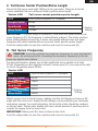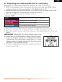
1
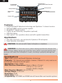
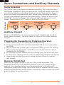
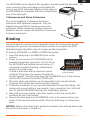
TM
AR7200BX User Guide
1
EN
NOTICE
All instructions, warranties and other collateral documents are subject
to change at the sole discretion of Horizon Hobby, Inc. For up-to-date
product literature, visit horizonhobby.com and click on the support tab
for this product.
Meaning of Special Language
The following terms are used throughout the product literature to indicate various levels of potential harm when operating this product:
NOTICE: Procedures, which if not properly followed, create a possibility
of physical property damage AND a little or no possibility of injury.
CAUTION: Procedures, which if not properly followed, create the probability of physical property damage AND a possibility of serious injury.
WARNING: Procedures, which if not properly followed, create the probability of property damage, collateral damage, serious injury or death
OR create a high probability of superficial injury.
WARNING: Read the ENTIRE instruction manual to become familiar
with the features of the product before operating. Failure to operate
the product correctly can result in damage to the product, personal
property and cause serious injury.
This is a sophisticated hobby product and NOT a toy. It must be operated
with caution and common sense and requires some basic mechanical
ability. Failure to operate this Product in a safe and responsible manner
could result in injury or damage to the product or other property. This
product is not intended for use by children without direct adult supervision. Do not attempt disassembly, use with incompatible components or
augment product in any way without the approval of Horizon Hobby, Inc.
This manual contains instructions for safety, operation and maintenance.
It is essential to read and follow all the instructions and warnings in the
manual, prior to assembly, setup or use, in order to operate correctly and
avoid damage or serious injury.
Age Recommendation: Not for children under 14 years. This is not
a toy.
WARNING AGAINST COUNTERFEIT PRODUCTS
Thank you for purchasing a genuine Spektrum product. Always purchase from a Horizon Hobby, Inc. authorized dealer to ensure authentic
high-quality Spektrum product. Horizon Hobby, Inc. disclaims all support
and warranty with regards, but not limited to, compatibility and performance of counterfeit products or products claiming compatibility with
DSM or Spektrum technology.
WARRANTY REGISTRATION
Visit www.spektrumrc.com/registration today to register your product.
2
EN
The AR7200BX combines the proven BeastX™ flybarless technology with a
Spektrum™ 7-channel, high-speed, 2048 receiver. This combination provides
the ultimate in performance and simple installation. The AR7200BX is perfect
for mini (up to 450 class) helicopters. Using an optional DSMX remote receiver
adds necessary path diversity for even the largest electric, glow, gas and
turbine-powered helicopters.The AR7200BX is compatible with all Spektrum
and JR® aircraft radios that support DSM2™ and DSMX technology. The
AR7200BX receiver is not compatible with the Spektrum DX6 park
flyer transmitter.
While the AR7200BX provides maximum agility and precision for intermediate
and professional pilots, it is not a flying aid for beginners.
Important: When using the AR7200BX with larger helicopters (500-size
and larger): It is necessary that you connect a DSMX remote receiver (not
included) to the AR7200BX before binding. See “Receiver Installation” for more
information.
CAUTION: DO NOT use DSM2 remote receivers with the AR7200BX.
Doing so will cause the helicopter to crash, resulting in property damage
and injury.
Box Contents
AR7200BX
Bind Plug
Gyropads
Adjustment tool
Instruction Manual
Program Guide
Optional Parts
DSMX Remote Receiver (SPM9645)
USB interface
Preflight Safety Precautions and Checklist
• Read all safety precautions and literature prior to use of this product.
• Always ensure the receiver and transmitter are properly bound before
flight.
• Always ensure batteries are fully charged and have proper capacity for
the flight time you intend.
• Always exit programming mode before flying.
• Always use the included gyropads and ensure they are properly mounted
and in good condition before each flight.
• Power your transmitter on first and then the receiver.
• Always allow the AR7200BX to initialize before flight.
• Confirm the cyclic and tail rotor servos do not bind at the full range of the
throw.
• Perform a control test, ensuring controls move in correct directions.
3
EN
Swashplate—
Direct Cyclic Feed Forward
Swashplate—
Cyclic Gain
Tail Dynamic
Setup Button
Menu Point
LED
Status LED
Features
• Integrated BeastX flybarless technology and Spektrum 7-channel receiver
• Optional DSMX remote receiver capable
• SmartSafe™ failsafe system
• Flight Log and Telemetry compatible (optional)
• 2048 Resolution
• High-speed 11ms operation when used with capable transmitters
Applications
• 250–800 sized nitro, gas and electric flybarless 3D helicopters
• Scale flybarless helicopters
CAUTION: Do not use with flybar helicopters or airplanes.
WARNING: For first-time use or when making mechanical changes that
involve throw, always ensure you reset the servo limits to prevent binding. Not
doing so will cause the helicopter to crash, resulting in property damage and
injury.
Specifications
Type: DSM receiver and BeastX flybarless technology
Channels: 7 (8 channels are available, however, Channel 5 is only used as an
internal gain channel for the tail gyro).
Modulation: DSM2, DSMX
Main Receiver Dimensions: 3 6mm x 28mm x 13 mm/
1.42 in x 1.1 in x .51 in
(Length x Width x Height)
Main Receiver Weight: 0.66 oz (18.6 g)
Voltage Range: 3.5 to 8.5V
Resolution: 2048
Frame Rate: 11ms
Compatibility: All DSM2 and DSMX aircraft transmitters and module systems
4
EN
Antenna Polarization
For optimum RF link performance, mount the antennas in an orientation
that allows for the best possible signal reception when the helicopter is in
all possible attitudes and positions. Orient the internal receiver antennas
perpendicular to each other (see Receiver Installation).
When using a DSMX remote receiver—Use double-sided foam tape to
mount the remote receiver so that the antenna is perpendicular to the longer
main receiver antenna. The remote receiver antenna must be at least 2 inches
away from the main receiver’s antenna. The AR7200BX is compatible with all
DSM2 and DSMX transmitters, even when using the optional DSMX remote
receiver.
AR7200BX installed in a
450-size helicopter
AR7200BX installed
in a 90-size helicopter
with remote
5
EN
Servo Connections and Auxiliary Channels
Servo Selection
Flight Direction
Select servos that are adequate for flybarless operation. The servos must have
high torque in addition to being fast and precise. Using high-quality servos that
are suited for flybarless helicopters increases the rotor blade options. A poor
servo-rotor blade combination will cause several issues including oscillations
in hover and unwanted reaction in fast forward flight. Connect all servos to the
AR7200BX. Refer to the diagram below for your particular helicopter’s cyclic
servos. Connect the pitch (PIT) servo to AUX1 on the AR7200BX.
Mechanical
Mixer
Electronic Mixer
90°
120°
AIL
AIL
PIT
AIL
140°
PIT
PIT
AIL
ELE
PIT
ELE
ELE
ELE
Auxiliary Channel
While the AR7200BX is a 7-channel receiver, Aux 3 is additionally offered for
more channel functions. The Gear channel is internal to the receiver used for
tail gain.
Preparing the Transmitter for Flybarless Operation
1. Create a new model in your transmitter’s model memory.
2. Be sure all trims/sub-trims are disabled (zeroed) and all servo travel values
are 100%.
3. Set your transmitter’s swash type to mechanical mixing (1 servo 90° mixing).
Never enable your transmitter’s eCCPM or revo-mixing functions. This is
handled by the AR7200BX.
4. Do not adjust the pitch curve at this time. During setup, the pitch curve must
be linear from -100% to +100% (or 0% to 100% depending on radio brand).
5. Again, make sure that there are no mixing functions active (for example
revo-mixing).
Receiver Installation
Attach the AR7200BX receiver using one of the provided gyropads. The
AR7200BX must be in a low vibration position, such as the receiver or gyro
platform. The mounting platform must be perpendicular to the main shaft.
Helicopters usually have enough room on the frame to separate the main feeder
antenna and the optional remote receiver. If necessary, make a mount using clear
plastic to attach the remote receiver.
6
EN
The AR7200BX can be attached flat, upright or inverted under the helicopter. The
servo connector pins must always point toward the
front or rear of the helicopter. Make sure the edges of
the AR7200BX are all parallel with the corresponding
axes of the helicopter.
Y-Harnesses and Servo Extensions
Do not use amplified Y-harnesses and servo
extensions with Spektrum equipment. Only use
standard non-amplified Y-harnesses and servo
extensions. When converting existing models to
Spektrum devices, replace all amplified Y-harnesses
and servo extensions.
Binding
You must bind the receiver to the transmitter before the receiver will operate.
Binding is the process of programming the receiver to recognize the GUID
(Globally Unique Identifier) code of a single specific transmitter..
To bind an AR7200BX to a DSM2 or DSMX transmitter:
1. Insert the bind plug in the BND/DAT port on the
receiver.
2. Power on the receiver (The AR7200BX can be
powered through any open port). The H LED on
the AR7200BX and external remote receiver (if
connected) should be flashing, indicating the
receiver is in bind mode.
AR7200BX with bind
To bind a helicopter with an electronic speed
plug inserted
controller that powers the receiver through the
throttle channel, insert the bind plug into the BND/DAT port in the receiver
and the ESC lead into the throttle (THRO) port.
3. Move the sticks and switches on the transmitter to the desired failsafe
positions (low throttle and neutral control positions).
4. Follow the procedures of your specific transmitter to enter Bind Mode. The
system will connect within a few seconds. Once connected, the H LED will
turn off and the AR7200BX will start the initialization process.
5. After setting up your model, rebind the system so the true low throttle
positions are set in the failsafe.
6. Remove the bind plug from the BND/DAT port on the receiver before you
power off the receiver and transmitter. Store the bind plug in a convenient
place.
NOTICE: Remove the bind plug to prevent the system from entering bind mode
the next time the power is turned on.
7
EN
Setup Procedure
Power on the transmitter first. The AR7200BX initializes when the receiver is
powered on. Do not move the AR7200BX or the helicopter while the receiver is
initializing. You can lay the helicopter on its side to prevent it from moving in
windy conditions.
Receiver Initialization Cycle
1. LEDs cycle and then the firmware version will display for 3 seconds.
2. LEDs H through N cycle to initialize the receiver inputs.
3. LEDs A through G cycle to calibrate the sensors.
4. The swashplate moves a small amount and the Status LED turns solid after
initialization completes.
Status-LED
Purple Solid
Tail gyro is in Normal-Rate mode
Blue Solid
Tail gyro is in Heading Lock mode
5. One of the LEDs A–N will light for 10 seconds to show the amount of tail
gain.
(A) = 0% to (N)=100%.
Switching Between Menu Levels
The AR7200BX has two menu levels—Setup Menu and Parameter Menu. You
must be in flight-ready mode (A–N LEDs off) to switch between menu levels.
Setup Menu—Access all basic settings for helicopter setup.
To access the Setup Menu: Press and hold the setup button until LED (A) stops
flashing and lights up solid.
Parameter Menu—Access settings to adjust the helicopter’s flight
characteristics. The Parameter Menu is used at the flying field.
To access the Parameter Menu: Press the setup button until LED (A) flashes
rapidly. Release the setup button when LED (A) flashes.
8
EN
Selection Within Menu Points
The Status LED color indicates menu point options. The options are:
Move the rudder stick left to move counterclockwise through the options. Move
the rudder stick right to move clockwise through the options. The available
options depend on the menu point.
Status-LED
LED solid:
LED flashing:
OFF
Purple Solid
Red Flashing
Red Solid
Blue Flashing
Blue Solid
Rudder Stick
Switching to the Next Menu Point
Quickly press the setup button to move to the next menu point. It is possible to
skip menu points by pressing the setup button. Do not move the transmitter sticks
when you are in a menu point you want to skip.
Exiting the Menu
When LED (N) is solid, quickly press the setup button to exit the menu. The
AR7200BX will also automatically exit the menu after 4 minutes of inactivity. The
AR7200BX will not automatically exit at points D, G, I and J to allow time for
mechanical helicopter adjustments.
CAUTION: Never fly the helicopter when the AR7200BX is in the Setup or
Parameter Menu. Gyro control and transmitter stick controls are disabled when
the AR7200BX is in the Setup or Parameter Menu.
Factory Reset
To erase all AR7200BX settings:
In any setup menu (A through N), press and hold the setup button for at least 10
seconds until LEDs (A) – (N) and (J) quickly flash to confirm the reset.
Any previous programming is deleted during a reset.
CAUTION: Do not attempt to fly the helicopter without doing a complete
setup procedure after a reset. If you do not complete the setup, the helicopter
will crash, causing property damage and injury.
Unplug all servos and remove the servo horns before resetting the AR7200BX.
9
EN
Setup Menu
The following section describes each menu point and the available settings.
A. Mounting Orientation
The AR7200BX can be mounted horizontally or vertically. The only restriction
is that the servo plug connectors MUST point toward the front or rear of the
helicopter.
Status-LED
Red Solid
Vertical (on the side)
Blue Solid
Horizontal (flat)*
*=Factory
Setting
Push the setup button to save the selection and move to menu point (B).
B. Swashplate Servo Frequency
CAUTION: If you do not know the maximum pulse rate for your servos,
do not exceed 50Hz servo frequency. A higher servo frequency can lead
to servo failure. Analog servos usually tolerate a maximum of 50Hz. Contact the
servo manufacturer if you are unsure of the servo frequency.
Always use the highest servo frequency that the servos will handle for the best
performance.
Status-LED
OFF
User Defined (requires PC software)
Purple Solid
50Hz*
Red Flashing
65Hz
Red Solid
120Hz
Blue Flashing
165Hz
Blue Solid
200Hz
*=Factory
Setting
Push the setup button to save the selection and move to menu point (C).
To see a complete Spektrum servo reference chart, refer to the servo chart on
spektrumrc.com.
10
EN
C. Tail Servo Center Position/Pulse Length
Almost all tail servos work with 1520µs (micro seconds). There are a few tail
servos available that use a different center position pulse length.
Status-LED
Tail servo center position pulse length
OFF
User Defined (requires PC software)
Purple Solid
960µs
Red Solid
760µs
Blue Solid
1520µs*
*=Factory
Setting
IMPORTANT: If a pulse length is selected (C) that does not allow a certain tail
servo frequency (D), the frequency is automatically reduced. The center position
pulse setting always has priority. A servo can operate without issue at a lower
frequency but cannot operate with an incorrect center position pulse length.
Push the setup button to save the selection and move to menu point (D).
D. Tail Servo Frequency
CAUTION: If you do not know the maximum frequency for your selected tail
servo, do not exceed 50Hz. Exceeding the maximum frequency for the tail
servo can lead to servo failure.
For best performance, always use a high-quality tail servo capable of at least
270Hz. Depending on the selection chosen in menu point (C), you may not be able
to select a frequency above 333Hz.
Status-LED
OFF
User Defined (requires PC software)
Purple Solid
50 Hz*
Red Flashing
165Hz
Red Solid
270Hz
Blue Flashing
333Hz
Blue Solid
560Hz
*=Factory
Setting
Attach a servo horn to the tail servo, making sure the tail linkage rod forms a 90°
angle with the servo horn. Adjust the tail linkage rod according to your helicopter
instruction manual. For most helicopters, the tail pitch slider should be centered
on the tail shaft. The tail rotor blades will have a small amount of positive pitch to
counter the torque from the main rotor.
IMPORTANT: Menu point (D) does not have a time limit.
Push the setup button to save the selection and move to menu point (E).
11
EN
E. Setting the Tail Servo Endpoints
Adjust the limit of the tail rotor blades to achieve the best throw. The best throw is
determined by either the maximum possible control travel of the tail slider or the
maximum allowed tail rotor blade angle of attack. Make sure the tail rotor blades
move in the correct direction (see your helicopter manual for more information).
If the tail rotor blades move in the wrong direction, reverse the rudder direction in
your transmitter.
To adjust the limits:
1. Move the rudder stick in one direction until the servo reaches the maximum
endpoint without binding. If you move the servo too far, move the rudder stick
in the opposite direction and move the tail pitch slider away from the limit.
2. Release the rudder stick.
3. Once the maximum endpoint is adjusted, don’t move the rudder stick.
4. Wait for the Status LED to flash and then turn Solid Red or Solid Blue,
depending on the direction. The servo limit for one direction is saved.
5. Adjust the servo limit in the opposite direction. Move the tail pitch slider to
the other maximum endpoint and release the rudder stick.
6. The Status LED flashes, followed by Solid Purple, indicating that the servo
endpoint adjustment is complete.
IMPORTANT: If the Status LED does not light or lights in an unexpected color, the
servo throw is too small. Move the tail linkage ball farther in toward the center of
the servo horn.
Push the setup button to save the selection and move to menu point (F).
F. Setting the Tail Sensor Direction
1. Move the helicopter nose to the right.
2. The tail rotor blades should move in the same direction as left rudder input.
3. If the tail rotor blades move in the wrong direction, you must reverse the
sensor direction.
4. Move the rudder stick once in any direction. The Status LED will change
color.
Status-LED
Red Solid
Normal*
Blue Solid
Reversed
*=Factory
Setting
5. Repeat the test as described above.
6. Push the setup button to save the selection and move to menu point (G).
12
EN
G. Adjusting the Swashplate Servo Centering
Menu point G electronically adjusts the center point of the cyclic servos.
1. With all swashplate servos connected, the servos are now operating in their
center position or “reference position”. The Status LED is Off.
2. Install the servo horns on the servos so the horns form an angle close to 90°
with the linkage rod. The angle will not be a perfect 90°.
3. Move the rudder stick once to select a servo.
Status-LED
OFF
Swashplate servos at reference position
Purple Solid
Elevator servo center adjust
Red Solid
Aileron servo center adjust
Blue Solid
Pitch servo center adjust
4. Move the elevator stick forward and back to adjust the center position.
5. Move the rudder stick to select the next servo. Complete Steps 3 & 4 for each
servo.
IMPORTANT: Menu point (G) does not have a time limit.
6. Adjust the cyclic/swashplate linkage rods according
to your helicopter manual. The swashplate should be
centered and the main blades should have 0° of pitch.
Always make rod length adjustments from the bottom
(servos) to the top (blade grips).
7. Push the setup button to save the selection and move
to menu point (H).
13
EN
H. Swashplate Mixer
Select the electronic swashplate mixer required for your helicopter or choose
“mechanical” if the helicopter uses a mechanical mixer. The AR7200BX supports
90°, 120° and 140° swashplates. You can also use any swashplate geometry by
selecting User Defined (PC software required). Refer to your helicopter manual for
more information on CCPM.
CAUTION: NEVER use your transmitter’s electronic swashplate mixing.
All CCPM mixing is done by the AR7200BX.
Status-LED
OFF
User Defined
Purple Solid
Mechanical
Red Flashing
90°
Red Solid
120° *
Blue Flashing
140°
Blue Solid
140° (1=1)
User Defined
Mechanical
90°120°
*=Factory Setting
140°
140° (1=1)
Push the setup button to save the selection and move to menu point (I).
14
EN
I. Setting the Swashplate Servo Directions
Menu point (I) ensures the swashplate servos are moving correctly. Note that the
proper aileron, elevator and collective pitch direction (right/left, up/down) will
be corrected later using the servo reversing setting in the transmitter. Try each of
the four possible combinations until the swashplate moves correctly. There is no
need to adjust servos individually.
IMPORTANT: The direction of swashplate movement (e.g. Swashplate moving
up when it should move down) is not important at this time. You will adjust the
swashplate direction when the servos are moving together.
1. Move the collective pitch stick and observe the swashplate movement. The
swashplate servos should all move together to raise or lower the swashplate.
2. If the swashplate is not horizontal when it moves, try a different servo
combination by moving the rudder stick.
3. Repeat Steps 1 & 2 until the servos are all moving together.
4. Now make sure the swashplate is moving in the correct direction (Refer to
your helicopter instruction manual).
5. If the swashplate is moving in the wrong direction (e.g. The swashplate is
moving up when it should move down), use the servo reverse feature in your
transmitter to reverse the appropriate channels.
Status-LED
AILE
ELEV
AUX1
OFF
normal
reverse
reverse
Purple Solid
normal*
normal *
reverse *
Red Solid
normal
reverse
normal
Blue Solid
normal
normal
normal
*=Factory Setting
IMPORTANT: Menu point (I) does not have a time limit. If the servos are
still not reacting properly after using servo reverse, make sure the servos are
connected to the proper receiver channels. Also, make sure any servo mixing in
your transmitter is turned off.
Push the setup button to save the selection and move to menu point (J).
15
EN
J. Teaching the Cyclic Pitch Geometry
CAUTION: Do not touch any stick on your transmitter when entering menu
point (J). This will cause unwanted flight behavior.
1. Move the rotor blades so that they are parallel to the tail boom.
2. Attach a pitch gauge to a rotor blade. The swashplate should be in the neutral
position and the blade should have 0° of pitch. If the swashplate is not
neutral with 0° of blade pitch, repeat menu point (G) before proceeding.
3. Move the aileron stick left or right until the pitch gauge has exactly 6° of
cyclic pitch.
IMPORTANT: The Status LED should still be Blue at 6° of cyclic pitch. If the
Status LED is Red, Purple or Off, you must mechanically adjust the helicopter.
You can use:
A.) Shorter servo horns
B.) Shorter linkage balls on the inner swashplate ring or
C.) Longer blade grip linkage levers
4. If the pitch gauge has more than 6° of cyclic pitch, move the aileron stick in
the opposite direction until the pitch gauge is at 6°.
5. Release the aileron stick and press the setup button once.
K. Adjusting the Collective Pitch Range
CAUTION: Do not use any pitch curves in your transmitter while adjusting
the Collective Pitch Range. Doing so will result in unwanted flight behavior.
1. Move the pitch stick all the way up (full positive pitch) and stay there.
2. Increase or decrease the maximum amount of positive pitch using the rudder
stick.
3. When you have achieved the desired maximum pitch angle, move the pitch
stick all the way down (full negative pitch).
4. Increase or decrease the maximum amount of negative pitch using the rudder
stick.
CAUTION: Make sure the blade pitch angle is moving in the correct
direction. Incorrect blade pitch angle can result in erratic flight behavior. If
the blade pitch is moving in the wrong direction, reverse the pitch channel in your
transmitter.
Push the setup button to save the selection and move to menu point (L).
16
EN
L. Adjusting the Cyclic Swashplate Limit
Menu point (L) adjusts the maximum possible tilting of the swashplate for aileron
and elevator. The deflection is limited in a circular path, similar to a cyclic ring
function, preventing swashplate binding at full aileron and elevator travel.
1. Carefully move the sticks for aileron, elevator and pitch to all maximum
endpoints. Watch for binding or lack of movement in the swashplate, linkage
rods and servos.
2. Move the rudder stick right or left to increase or decrease the aileron and
elevator throw limiter. Always try to achieve the maximum possible cyclic
throw without causing binding.
3. The Status-LED should still be Blue when the swashplate is at the maximum
limit. If the Status-LED is Purple or Off, you must mechanically adjust the
helicopter to increase the available throw.
IMPORTANT: If you make any modifications to menu points (G), (J) or (K) in the
future, you must repeat menu point (L) again.
Push the setup button to save the selection and move to menu point (M).
M. Setting the Swashplate Sensor Directions
1. Tilt the helicopter forward. The swashplate should tilt backward.
2. Tilt the helicopter backward. The swashplate should tilt forward.
3. Roll the helicopter left. The swashplate should roll right.
4. Roll the helicopter right. The swashplate should roll left.
5. If the swashplate does not move in the correct direction, you will need to
reverse the sensor direction by moving the rudder stick to select one of the
following options. There are four options:
Status-LED
Elevator
Aileron
OFF
reversed
reversed
Purple Solid
reversed
normal
Red Solid
normal
reversed
Blue Solid
normal*
normal*
*=Factory
Setting
6. Repeat Step 5 until both sensors are working in the correct direction.
7. Push the setup button to save the selection and move to menu point (N).
17
EN
N. Setting the Pirouette Optimization Direction.
1. Note the direction the swashplate tilts when entering menu point (N). The
swashplate will tilt forward or back; the direction does not matter.
2. Hold the helicopter at the rotor head and spin the helicopter by hand around
the main shaft.
3. The swashplate should remain in the same tilt direction regardless of the
rotational direction of the helicopter.
4. If the swashplate changes direction and rotates against the direction of the
helicopter, use the rudder stick to change the direction.
5. Push the setup button to save the selection and exit the Setup Menu (N).
The setup steps of the AR7200BX are finished. It is now necessary to continue
setting up the dials and parameters options.
Status-LED
Pirouette Optimization Direction
Red Solid
Normal*
Blue Solid
Reversed
*=Factory
Setting
18
EN
AR7200BX Power System Requirements
All flybarless gyro systems require uninterrupted power.
During even a short duration power interruption/brownout, the flybarless unit
must reboot and reinitialize.
CAUTION: If a power interruption/brownout occurs during flight, a crash
will occur. It is your responsibility to ensure the AR7200BX has sufficient
power without interruption.
Some of the power system components that affect the ability to properly deliver
adequate power include:
• The switch harness, battery leads, servo leads, regulators etc.
• Receiver battery pack (number of cells, capacity, cell type, state of charge)
• The ESC’s BEC capability to deliver current to the receiver when load is
placed on the servos. This is the #1 cause of power interruptions in electric
helicopters.
The AR7200BX has a minimum operational voltage of 3.5 volts; it is highly
recommended the power system be tested per the following guidelines.
Recommended Power System Test Guidelines
Perform the following test with a voltmeter. The Spektrum Flight Log or Telemetry
Modules (TM1000/TM1100) work well for this test.
Plug the Flight Log into an open channel port in the receiver and, with the
system on, load the servos by applying pressure to the swashplate with your
hand for 3 minutes. Monitor the voltage at the receiver. It is important to load
the swashplate for 3 minutes. If a voltage regulator becomes hot, it can lose it’s
ability to supply current. An alternate method is to power on the system and
rapidly move the control sticks (stir the sticks) with no load on the servos for 3
minutes. The voltage should remain above 4.8 volts in both cases.
19
EN
SmartSafe™ Failsafe
SmartSafe is a safety feature on the throttle channel only that offers the following
benefits:
• Prevents electric motors from operating when the receiver only is turned on
(no transmitter signal present)
• Prevents the speed controller from arming until the throttle is moved to low
throttle position after connection is made
• Powers off electric motors and reduces gas/glow engines to idle if signal is
lost
(Must bind the receiver at throttle off or idle position).
• If throttle is at any position other than low, the ESC won’t arm
• If connection is lost in flight:
SmartSafe sets the throttle to the position it was in during the binding process
(normally low throttle or idle).
How To Program
SmartSafe is automatically set when the system is bound. It’s important to have
the throttle stick in the low position to store low throttle during binding.
To Test
Electric helicopters: Remove the pinion gear from the motor before testing.
Gas or glow helicopters: Test the servo positions with the engine off.
Confirm the failsafe setting is correct by turning off the transmitter. The throttle
should go to the preset low throttle position. All other channels should hold the
last commanded position.
Range Testing
Before each flying session, and especially with a new model, perform a range
check. All Spektrum aircraft transmitters incorporate a range testing system
which, when activated, reduces the output power, allowing a range check.
1. With the model on the ground and the motor/engine off, stand 30 paces
(approx. 90 feet/28 meters) away from the model.
2. Face the model with the transmitter in your normal flying position and place
your transmitter into range check mode. This causes reduced power output
from the transmitter.
3. You should have total control of the model in range test mode at 30 paces.
4. If control issues exist, call the Horizon Product Support office.
20
EN
Dials and Tail Gyro Gain
To adjust the dials: Only use the original Spektrum AR7200BX adjustment tool to
prevent damage to the dials.
Dial 1: Swashplate—Cyclic Gain
Turn Dial 1 clockwise to increase the swashplate gain.
Factory setting for Dial 1 is horizontal (50% swashplate gain). Use
the factory setting for your first flights. Typically this setting is ideal
for 450 class helicopters. If you are flying larger helicopters it may
be necessary to slightly increase the cyclic gain positions.
The higher the gain, the more aggressively the helicopter will stop after cyclic
movement and the helicopter will feel more stable in the air.
Cyclic Gain Too High
Helicopter feels “soft” in flight and tends to
oscillate on the elevator axis.
Cyclic Gain Too Low
The helicopter will feel softer, slower and less
direct.
Dial 2: Swashplate—Direct Cyclic Feed Forward
Turn Dial 2 clockwise to increase the swashplate’s direct cyclic stick feed forward.
The direct cyclic stick feed is the part of the stick input going directly to the servos.
When correctly adjusted, the direct stick feed allows the control loop to make small
corrections and work more efficiently.
Factory setting for Dial 2 is horizontal.
Direct Cyclic Feed
Forward Too High
This causes over-control in your cyclic input.
When set too high, the control loop overshoots and
needs a steer back correction. This causes pitch
backs (bobbles) on cyclic stops and imprecise fast
forward flight.
Direct Cyclic Feed
Forward Too Low
The helicopter will feel softer, slower and less
direct.
Increasing the direct cyclic feed forward will cause more cyclic stick input to go
directly to the aileron and elevator on the swashplate giving a more responsive feel.
Decreasing the direct stick feed forward does the opposite.
The optimal setting depends on many factors, including blades, servos, head
speed, size and mass of the helicopter.
IMPORTANT: The direct cyclic feed forward does not affect the maximum rate of
rotation. If the helicopter rotates too slowly:
1. Check the swashplate limiter settings in Setup menu point (L)
2a.Change the control behavior in Parameter menu point (B) or
2b.Increase the servo travels or dual rate in your transmitter
21
EN
Dial 3: Tail Dynamic
Turn Dial 3 clockwise to increase the tail dynamic or counterclockwise to decrease
the tail dynamic.
Factory setting for Dial 3 is horizontal
Make sure the maximum possible tail gyro gain has already been determined
before adjusting the tail dynamic.
Increasing the Tail Dynamic
This will lead to harder stopping behavior
and more aggressive response to tail stick
inputs.
Tail Dynamic Too High
The tail will bounce back shortly after a
hard stop and feel soft when making fast
direction changes.
Tail Dynamic Too Low
Stopping might be too soft.
The tail should stop perfectly to the point without making any flapping noises.
Transmitter adjustment: Tail Gyro Gain
Tail gain can be adjusted using the transmitter’s gear channel. Most transmitters
have a gyro screen that allows gyro adjustments. It is important that the gyro
function is assigned to the gear channel in the transmitter.
Status-LED
Purple Solid
Blue Flashing
Blue Solid
Rate Mode
Heading Lock Mode
The color of the Status LED indicates the selected mode when the AR7200BX is
ready for operation.
When the gain channel is centered, LED A = 0% gain. The maximum adjustable tail
gain is 100% in both modes (LED N = 100%). One of the LEDs A–N will light for
10 seconds to show the amount of tail gain. (A) = 0% to (N)=100%.
For the first flights, do not use a gain higher than F or G in Heading Lock mode.
22
EN
To find the optimal gain:
1. Start with a low gain value where the tail will feel very weak.
2. Increase the gain step by step until the tail feels more precise and holds better
on sudden pitch inputs.
3. If the gain is too high, “wagging” will appear in fast forward or backward
flight.
N M
M N
L K
Menu LED:
K L
J I
I J
H G
H
F E
F G
D C
D E
B A B C
Rate-Mode
HeadingLock-Mode
Status-LED: Purple
0%
Status LED: Blue
Tail gyro gain (CH 5)
-100%
100%
Parameter Menu
To enter the Parameter Menu:
1. When the AR7200BX is ready for flight, press and hold the setup button until
the LED flashes next to menu point (A).
2. Release the setup button.
3. Press the setup button once to move to the next menu point. The Parameter
Menu only has 8 menu points (A through H).
4. Press the setup button once at menu point (H) to exit the Parameter Menu.
It is possible to skip menu points. Do not move the transmitter sticks when you
are in a menu point you want to skip. Quickly press the setup button again to
move past the menu point you want to skip.
CAUTION: Never fly the helicopter when the AR7200BX is in the Setup or
Parameter Menu. Gyro control and transmitter stick controls are disabled
when the AR7200BX is in the Setup or Parameter Menu.
A. Swashplate Cyclic Center Adjustment
NOTICE: NEVER USE TRANSMITTER TRIMS WITH THE AR7200BX!
The AR7200BX will interpret the trim as a control command, NOT as servo trim.
Menu point A allows you to easily adjust your servo centers at the flying field if
the helicopter is wobbling during pirouettes or not climbing out straight on quick
pitch inputs.
Parameter menu point (A) adjusts both the aileron and elevator servo centers
without regard to the individual servos.
To adjust the aileron and elevator servo centers:
1. Move the aileron or elevator stick in the desired direction.
2. Repeatedly move the stick or hold the stick to move several trim steps at once.
3. To delete the trimming, move the tail stick in any direction.
23
EN
IMPORTANT: Unlike digital trims in the transmitter, menu point (A) is not a separate trim function. If the new center position is saved once in Parameter menu point
(A), it will also change the servo center position in Setup menu point (G).
Once the center position is saved in menu point (A), it is no longer
possible to delete the trimming.
Press the setup button once to move to Parameter menu point (B).
B. Control Behavior
Menu point (B) allows you to select between different control behaviors for your
helicopter, including the maximum rotation rate and exponential.
Factory setting is “Sport”, which should be suitable for most pilots.
“Normal” has a decreased rotation rate for cyclic and tail controls, as well as
increased exponential. When you are comfortable flying in “Normal”, find your
personal preference by increasing the Control Behavior one option at a time.
To use your own transmitter settings instead of the presets, select Status LED: Blue
Solid.
Status-LED
Control Behavior
OFF
User Defined
Purple Solid
Normal
Red Flashing
Sport*
Red Solid
Pro
Blue Flashing
Extreme
Blue Solid
Transmitter
*=Factory
Setting
If you select one of the preset Control Behaviors, do not use Exponential and/or
Dual Rates in your transmitter. Slightly increasing servo travel in your transmitter
should not cause any problems with the Control Behaviors.
The option “User Defined” allows you to define your own settings using the
optional PC Software.
Press the setup button once to move to Parameter menu point (C).
C. Swashplate – Pitching Up Compensation
1. While in fast forward flight, apply sudden collective pitch inputs. The
helicopter should remain in its horizontal path during climb and descend.
2. If the nose of the helicopter pitches up and down, increase the Pitch Up
Compensation.
3. If the value is too high, the helicopter may feel sluggish. Try to find the lowest
suitable setting.
4. If the helicopter still pitches up at the highest value, increase the swashplate
gain (Dial 1).
24
EN
5. If the helicopter continues to pitch up after increasing the swashplate gain,
you may need to use faster and stronger servos or blades designed for
flybarless helicopters.
Status-LED
Pitching Up Behavior
OFF
User Defined
Purple Solid
Very Low
Red Flashing
Low
Red Solid
Medium*
Blue Flashing
High
Blue Solid
Very High
*=Factory
Setting
The option “User Defined” allows you to define your own settings using the
optional PC Software.
Press the setup button once to move to Parameter menu point (D).
D. Tail Heading Lock Gain
Heading Lock gain determines how constant the tail will maintain the rotation rate
from the rudder stick.
1. Start with Heading Lock gain set to low or very low and maximize the tail gain
in your transmitter.
2. Increase the Heading Lock gain in the AR7200BX until the desired result are
achieved.
Heading Lock Gain Too Low Pirouettes are inconsistent in fast forward
flight or in crosswind conditions.
Heading Lock Gain Too High
Fast tail-direction changes are more
difficult to control. The tail may also move
gently while hovering or flying around
and will bounce back when stopping the
rotation.
When the appropriate setting is determined, it is usually necessary to re-adjust the
tail gyro gain in the transmitter.
Status-LED
Tail Heading Lock Gain
OFF
User Defined
Purple Solid
Very Low
Red Flashing
Low
Red Solid
Medium*
Blue Flashing
High
Blue Solid
Very High
*=Factory
Setting
25
EN
IMPORTANT: If the tail pirouettes and stops unevenly in both directions, set
the tail gyro to Normal-Rate mode. Test whether the tail will drift in a particular
direction during hover. If it does, adjust the tail link rod length so the tail rotor
blades have the required compensation for pitch. If you adjust the tail link rod
length, you must reset the tail rotor limits (Setup menu point (E)). If you chose
“Transmitter” in the Control Behavior (Parameter menu point (B)), make sure you
are not entering the free spinning range, which can cause inconsistent rotation.
The option “User Defined” allows you to define your own settings using the
optional PC Software.
Press the setup button once to move to Parameter menu point (E).
E. Stick Deadband
Stick deadband is the range around the very center of the stick where the
AR7200BX will not react. Depending on the calibration of the transmitter, the sticks
may not be in the exact same center position each time they return to center. This
can cause unwanted rotation on the axis of stick movement.
Stick Deadband
Set Too Low
It is difficult to find a stick position where no input is
sent to the AR7200BX. A setting too low can lead to
a helicopter tipping on takeoff or a helicopter that is
difficult to control.
Stick Deadband
Set Too High
You will feel a large range of stick movement where you
have no control. A setting too high can lead to difficult
precision hovering.
Status-LED
Stick Deadband
OFF
User Defined
Purple Solid
1
Red Flashing
2*
Red Solid
3
Blue Flashing
4
Blue Solid
5
*=Factory
Setting
The option “User Defined” allows you to define your own settings using the
optional PC Software.
Press the setup button once to move to Parameter menu point (F).
26
EN
F. Tail—RevoMIX
The AR7200BX can pre-compensate for torque variations on the tail before any
noticeable change. RevoMIX relieves the tail control loop and improves tail
performance on helicopters with insufficient tail authority and/or high powered
electric helicopters.
To see the compensation direction:
1. Move the collective pitch, roll and elevator stick at any time. The tail rotor has
to deflect to counter the rotor torque. The tail rotor blades deflect the least
when the main rotor is at 0° pitch (the point where the main rotor produces
the least torque).
2. Pitch positive or negative direction, move the aileron or elevator control. A
deflection is added to the tail rotor to counter the torque. The height of the
deflection depends on the collective pitch angles in Setup menu point K. The
deflection may vary depending on the direction of pitch.
3. A helicopter with a clockwise rotation main rotor will steer the nose of the
helicopter to the right. When control input is given, the tail slider/tail rotor
will move slightly in a given direction.
4. Cycle through the options and find the direction that matches your model.
You then have four options: Off, Low, High or By Computer.
Status-LED
Torque Precompensation
OFF
User Defined
Purple Solid
Off*
Red Flashing
Low—Normal Direction
Red Solid
High—Normal Direction
Blue Flashing
Low—Reverse Direction
Blue Solid
High—Reverse Direction
*=Factory
Setting
The option “User Defined” allows you to define your own settings using the
optional PC Software.
Press the setup button once to move to menu point ( G ).
27
EN
G. Cyclic Response
Menu point ( G ) adjusts how aggressively the AR7200BX responds to cyclic
commands (roll and pitch). Adjusting the cyclic response can reduce the linear
control feeling of flybarless systems and make the helicopter response feel more
like a flybar helicopter.
The factory setting is “Normal”. To use the cyclic response feature, select
“Slightly Increased” from the options. Gradually increase the cyclic response until
you reach the desired level.
Cyclic Response Too High: Results in uncontrollable, inaccurate rotation and
deteriorated stopping behavior.
The maximum amount of cyclic response is determined by many factors, including:
heli size, swashplate servos, main rotor blades, head speed, servo power supply
and helicopter setup.
The option “User Defined” allows you to define your own settings using the
optional PC Software.
Press the setup button once to move to menu point ( H ).
Status-LED
Cyclic Response
OFF
User Defined
Purple Solid
Normal*
Red Flashing
Slightly Increased
Red Solid
Increased
Blue Flashing
High
Blue Solid
Very High
*=Factory
Setting
H. Pitch Boost
Pitch boost is useful in 3D aerobatics when rapid pitch changes are necessary for
certain flight maneuvers. Additional collective pitch will be added as you move the
pitch stick faster.
Pitch boost will not exceed the maximum pitch value set in Setup menu point ( K ).
Start from the “low” setting and gradually increase to the desired level.
The maximum amount of pitch boost is determined by many factors, including:
maximum pitch values, pitch curve, swashplate servos, main rotor blades and head
speed.
28
EN
Pitch Boost Setting Too High: Can cause the rotor blades to stall when you
input fast pitch commands. The collective pitch will feel slow, the opposite of the
desired effect.
Status-LED
Pitch Boost
OFF
User Defined
Purple Solid
Off*
Red Flashing
Low
Red Solid
Medium
Blue Flashing
High
Blue Solid
Very High
*=Factory
Setting
The option “User Defined” allows you to define your own settings using the
optional PC Software.
Press the setup button once to exit the Parameter menu.
29
EN
The First Flight
After powering on the receiver, wait for the AR7200BX to initialize completely (Short
movement of swashplate servos and Status LED is Solid Blue or Solid Purple).
It is not necessary for the helicopter to be horizontal. Do not move the helicopter at
any time during the initialization. You can lay the helicopter on its side to prevent
shaking in wind.
CAUTION: Always complete a control direction test with the transmitter and
make sure the sensors are correcting in the proper directions when you tilt,
roll and yaw the helicopter by hand.
It is normal for the swashplate to slowly move back to its original
position after a stick input and for the servos to not move at the same
speed as your control sticks.
When using a flybarless rotor head, you are controlling rotational rates while the AR7200BX controls the servos. You are not directly controlling the servos with the transmitter.
Heading Lock Mode: It is normal for the tail servo to:
1. Stay in its end position after a tail stick input or tail movement.
2. Not react immediately to a stick input.
3. Move to the endpoints with small stick inputs.
CAUTION: Remove main and tail rotor blades before the first flight.
Allow the motor/engine to run at all speeds. Watch for the swashplate to
automatically tilt in one direction or begin to twitch at a specific speed. These are
signs that the helicopter has mechanical vibration that will disturb the AR7200BX
sensors.
Correct any sources of mechanical vibration before the first flight.
Just before lift off, make sure the swashplate is horizontal and the tail pitch slider
is near centered.
Avoid excessive steering during lift off, otherwise the helicopter may
tip over and crash!
Give direct collective pitch input to quickly lift the helicopter into the air. This will
require some practice if you do not have experience with flybarless helicopters.
30
EN
Version Display
After the AR7200BX initializes, the Status LED turns Solid Red for 3 seconds.
The first two digits of the internal firmware version are displayed.
Representation of Values
The representation of all values using the menu LEDs is in binary. A lighting
menu LED stands for a 1, an off LED for 0. The least significant bits are A and
H.
Firmware Version
The firmware version consists of three values X, Y, and Z which are
displayed for X and Y during the initialization, and for Z if the button is pushed
during this initialization. X is displayed though menu LEDs A - G, Y through
H - N and Z is using all LEDs A - N.
Data Version
The data version consists of two values X and Y, which are displayed at the same
time through menu LEDs A - G for X and H - N for Y.
Hardware Version
The hardware version consists of two values X and Y, which are displayed at the same
time through menu LEDs A - G for X and H - N for Y.
Servo Reference Chart
Swashplate
Servo
Tail
Frequency
Center-Position
Frequency
Color
Hz
Color
µs
Color
Hz
SPMSH3000
Red Flashing
65 Hz
Blue Solid
1520 µs
Purple
50 Hz
SPMSH3020
Blue Solid
200 Hz
Blue Solid
1520 µs
Red Flashing
165 Hz
Blue Solid
200 Hz
Blue Solid
1520 µs
Red Flashing
165 Hz
Blue Solid
200 Hz
Blue Solid
1520 µs
Red Flashing
165 Hz
SPMSH5000
SPMSH5010
SPMSH6010
Red Flashing
65 Hz
Blue Solid
1520 µs
Purple
50 Hz
SPMSH6040
Blue Solid
200 Hz
Blue Solid
1520 µs
Red Flashing
165 Hz
SPMSH6080G
Blue Solid
200 Hz
Blue Solid
1520 µs
Blue Flashing
333 Hz
SPMSH5020G
Blue Solid
200 Hz
Blue Solid
1520 µs
Solid Red
270 Hz
31
EN
AR7200BX Overview
SETUP MENU Menu LED solid
Status-LED:
A
B
C
D
E
F
G
H
I
J
K
L
M
OFF
Red
Flashing
Purple
Blue
Flashing
upright
(vertical)
Mounting orientation
50 Hz*
User defined
960 μs
Tail servo - frequency
User defined
50 Hz*
Tail servo - rotor
Tail stick - move to right endpoint and wait/left endpoint and wait
65 Hz
120 Hz
Blue
Solid
flat
(horizontal)*
User defined
Swashplate servo
165 Hz
200 Hz
- frequency
Tail servo - center
760 μs
1520 μs*
position pulse length
165 Hz
270 Hz
333 Hz
560 Hz
endpoints
Tail - sensor direction
Swashplate - servo
reference
position
ELE center
pos.
Swashplate - mixer
User defined
mechanical
Swashplate - servo
nor|rev|rev
nor|nor|rev*
centering
90°
normal*
reversed
AIL center
pos.
PIT center
pos.
120°*
140°
140° (1=1)
nor|rev|nor
nor|nor|nor
directions
Swashplate - cyclic
pitch geometry
Aileron stick – adjust 6° cyclic pitch on the roll axis (blades aligned with fuselage)
Collective pitch range
Collective stick on max and min position and use tail stick to adjust desired pitch
Swashplate - cyclic
Move aileron, elevator and pitch sticks – adjust max limits with tail stick
limit
Swashplate - sensor
rev | rev
rev | nor
nor | rev
nor | nor*
normal*
reversed
directions
Pirouette
N
Red
Solid
optimization
direction
*=Factory Setting
PARAMETER MENU Menu LED is flashing quickly
Status-LED:
A
Swashplate -
OFF
Red
Flashing
Purple
Red
Solid
Blue
Flashing
Blue
Solid
Aileron and elevator stick – reset with tail stick
cyclic center
B
adjustment
Control behavior
User defined
normal
sport*
pro
extreme
transmit-
C
Swashplate - pitching
User defined
very low
low
medium*
high
ter
very high
D
up behavior
Tail - HeadingLock
User defined
very low
low
medium*
high
very high
E
F
gain
Stick deadband
Tail - torque
User defined
User defined
1
off*
2*
low - nor
3
high - nor
4
low - rev
5
high - rev
G
H
precompensation
Cyclic response
Pitch boost
User defined
User defined
normal*
off*
high
high
very high
very high
slightly increased increased
low
medium
*=Factory Setting
32
EN
1-Year Limited Warranty
What this Warranty Covers
Horizon Hobby, Inc., (Horizon) warrants to the original purchaser that the
product purchased (the “Product”) will be free from defects in materials and
workmanship for a period of 1 years from the date of purchase.
What is Not Covered
This warranty is not transferable and does not cover (i) cosmetic damage, (ii)
damage due to acts of God, accident, misuse, abuse, negligence, commercial
use, or due to improper use, installation, operation or maintenance, (iii)
modification of or to any part of the Product, (iv) attempted service by anyone
other than a Horizon Hobby authorized service center, or (v) Products not
purchased from an authorized Horizon dealer.
OTHER THAN THE EXPRESS WARRANTY ABOVE, HORIZON MAKES NO OTHER
WARRANTY OR REPRESENTATION, AND HEREBY DISCLAIMS ANY AND ALL
IMPLIED WARRANTIES, INCLUDING, WITHOUT LIMITATION, THE IMPLIED
WARRANTIES OF NON-INFRINGEMENT, MERCHANTABILITY AND FITNESS FOR
A PARTICULAR PURPOSE. THE PURCHASER ACKNOWLEDGES THAT THEY
ALONE HAVE DETERMINED THAT THE PRODUCT WILL SUITABLY MEET THE
REQUIREMENTS OF THE PURCHASER’S INTENDED USE.
Purchaser’s Remedy
Horizon’s sole obligation and purchaser’s sole and exclusive remedy shall be
that Horizon will, at its option, either (i) service, or (ii) replace, any Product
determined by Horizon to be defective. Horizon reserves the right to inspect
any and all Product(s) involved in a warranty claim. Service or replacement
decisions are at the sole discretion of Horizon. Proof of purchase is required for
all warranty claims. SERVICE OR REPLACEMENT AS PROVIDED UNDER THIS
WARRANTY IS THE PURCHASER’S SOLE AND EXCLUSIVE REMEDY.
Limitation of Liability
HORIZON SHALL NOT BE LIABLE FOR SPECIAL, INDIRECT, INCIDENTAL
OR CONSEQUENTIAL DAMAGES, LOSS OF PROFITS OR PRODUCTION OR
COMMERCIAL LOSS IN ANY WAY, REGARDLESS OF WHETHER SUCH CLAIM IS
BASED IN CONTRACT, WARRANTY, TORT, NEGLIGENCE, STRICT LIABILITY OR
ANY OTHER THEORY OF LIABILITY, EVEN IF HORIZON HAS BEEN ADVISED OF
THE POSSIBILITY OF SUCH DAMAGES. Further, in no event shall the liability of
Horizon exceed the individual price of the Product on which liability is asserted.
As Horizon has no control over use, setup, final assembly, modification or
misuse, no liability shall be assumed nor accepted for any resulting damage
or injury. By the act of use, setup or assembly, the user accepts all resulting
liability. If you as the purchaser or user are not prepared to accept the liability
associated with the use of the Product, purchaser is advised to return the
Product immediately in new and unused condition to the place of purchase.
Law
These terms are governed by Illinois law (without regard to conflict of law
principals). This warranty gives you specific legal rights, and you may also
33
EN
have other rights which vary from state to state. Horizon reserves the right to
change or modify this warranty at any time without notice.
WARRANTY SERVICES
Questions, Assistance, and Services
Your local hobby store and/or place of purchase cannot provide warranty
support or service. Once assembly, setup or use of the Product has been
started, you must contact your local distributor or Horizon directly. This will
enable Horizon to better answer your questions and service you in the event
that you may need any assistance. For questions or assistance, please direct
your email to [email protected], or call 877.504.0233
toll free to speak to a Product Support representative. You may also find
information on our website at www.horizonhobby.com.
Inspection or Services
If this Product needs to be inspected or serviced, please use the Horizon Online
Service Request submission process found on our website or call Horizon to
obtain a Return Merchandise Authorization (RMA) number. Pack the Product
securely using a shipping carton. Please note that original boxes may be
included, but are not designed to withstand the rigors of shipping without
additional protection. Ship via a carrier that provides tracking and insurance for
lost or damaged parcels, as Horizon is not responsible for merchandise until it
arrives and is accepted at our facility. An Online Service Request is available at
http://www.horizonhobby.com under the Support tab. If you do not have internet
access, please contact Horizon Product Support to obtain a RMA number along
with instructions for submitting your product for service. When calling Horizon,
you will be asked to provide your complete name, street address, email address
and phone number where you can be reached during business hours. When
sending product into Horizon, please include your RMA number, a list of the
included items, and a brief summary of the problem. A copy of your original
sales receipt must be included for warranty consideration. Be sure your name,
address, and RMA number are clearly written on the outside of the shipping
carton.
Notice: Do not ship LiPo batteries to Horizon. If you have any issue
with a LiPo battery, please contact the appropriate Horizon Product
Support office.
Warranty Requirements
For Warranty consideration, you must include your original sales
receipt verifying the proof-of-purchase date. Provided warranty conditions
have been met, your Product will be serviced or replaced free of charge.
Service or replacement decisions are at the sole discretion of Horizon.
34
EN
Non-Warranty Service
Should your service not be covered by warranty service will be
completed and payment will be required without notification or
estimate of the expense unless the expense exceeds 50% of the
retail purchase cost. By submitting the item for service you are agreeing
to payment of the service without notification. Service estimates are available
upon request. You must include this request with your item submitted for
service. Non-warranty service estimates will be billed a minimum of ½ hour
of labor. In addition you will be billed for return freight. Horizon accepts money
orders and cashiers checks, as well as Visa, MasterCard, American Express,
and Discover cards. By submitting any item to Horizon for service, you are
agreeing to Horizon’s Terms and Conditions found on our website http://www.
horizonhobby.com/Service/Request/.
Warranty and Service Contact Information
Country of
Purchase
United
States of
America
United
Kingdom
Germany
France
China
Horizon
Hobby
Horizon Service Center
(Electronics
and engines)
Horizon
Product Support (All other
products)
Phone Number/Email
Address
877-504-0233
4105 Fieldstone Rd
Online Repair Request:
Champaign, Illinois
visit www.horizonhobby.
61822 USA
com/service
Address
4105 Fieldstone Rd 877-504-0233
Champaign, Illinois productsupport@horizon61822 USA
hobby.com
Units 1-4 Ployters
Rd
Horizon Hob- Staple Tye
by Limited
Harlow, Essex
CM18 7NS
United Kingdom
Christian-JungeHorizon
Straße 1
Technischer
25337 Elmshorn
Service
Germany
14 Rue Gustave
Eiffel
Horizon
Zone d’Activité du
Hobby SAS
Réveil Matin
91230 Montgeron
Room 506, No. 97
Horizon
Changshou Rd.
Hobby –
Shanghai, China
China
200060
35
+44 (0) 1279 641 097
sales@horizonhobby.
co.uk
+49 (0) 4121 2655 100
[email protected]
+33 (0) 1 60 47 44 70
infofrance@horizonhobby.
com
+86 (021) 5180 9868
info@horizonhobby.
com.cn
EN
FCC Information
This device complies with part 15 of the FCC rules. Operation is subject to the following
two conditions: (1) This device may not cause harmful interference, and (2) this device must
accept any interference received, including interference that may cause undesired operation.
Caution: Changes or modifications not expressly approved by the party
responsible for compliance could void the user’s authority to operate the equipment.
This product contains a radio transmitter with wireless technology which has been tested and
found to be compliant with the applicable regulations governing a radio transmitter in the
2.400GHz to 2.4835GHz frequency range.
Customer Service Information
Country of
Horizon
Purchase
Hobby
United
States of
Sales
America
United
Kingdom
Germany
France
China
Address
Phone Number/Email
Address
4105 Fieldstone Rd (800) 338-4639
Champaign, Illinois sales@horizonhobby.
61822 USA
com
Units 1-4 Ployters
Rd
Horizon
Staple Tye
Hobby
Harlow, Essex
Limited
CM18 7NS
United Kingdom
Christian-JungeStraße 1
Horizon
Hobby GmbH 25337 Elmshorn
Germany
14 Rue Gustave
Eiffel
Horizon
Zone d’Activité du
Hobby SAS
Réveil Matin
91230 Montgeron
Room 506, No. 97
Horizon
Changshou Rd.
Hobby –
Shanghai, China
China
200060
36
+44 (0) 1279 641 097
sales@horizonhobby.
co.uk
+49 4121 46199 60
service@horizonhobby.
de
+33 (0) 1 60 47 44 70
[email protected]
+86 (021) 5180 9868
info@horizonhobby.
com.cn
EN
Compliance Information for the
European Union
Declaration of Conformity
(in accordance with ISO/IEC 17050-1)
No. HH2011111302
Product(s): Item Number(s):
Equipment class:
AR7200BX 7CH Flybarless Control System
SPMAR7200BX
1
The object of declaration described above is in conformity with the requirements of the
specifications listed below, following the provisions of the European R&TTE directive 1999/5/
EC:
EN 301 489-1 V1.7.1: 2006
EN 301 489-17 V1.3.2: 2008
Signed for and on behalf of:
Horizon Hobby, Inc.
Champaign, IL USA
November 13, 2011
Steven A. Hall
Vice President
International Operations and Risk Management
Horizon Hobby, Inc.
Instructions for disposal of WEEE by users in the
European Union
This product must not be disposed of with other waste. Instead, it
is the user’s responsibility to dispose of their waste equipment by
handing it over to a designated collections point for the recycling of
waste electrical and electronic equipment. The separate collection and recycling
of your waste equipment at the time of disposal will help to conserve natural
resources and ensure that it is recycled in a manner that protects human health and
the environment. For more information about where you can drop off your waste
equipment for recycling, please contact your local city office, your household waste
disposal service or where you purchased the product.
37
© 2011 Horizon Hobby, Inc.
DSMX is a trademark of Horizon Hobby, Inc., registered in the U.S.
DSM, DSM2, SmartSafe and JR are trademarks or registered trademarks of Horizon Hobby, Inc.
The Spektrum trademark is used with permission of Bachmann Industries, Inc.
BeastX is a trademark of Markus Schaack and is used with permission.
The Spektrum AR7200BX employs technology exclusively licensed to Horizon Hobby, Inc.
from freakware GmbH.
US 7,391,320. Other patents pending.
Created 11/11 32660