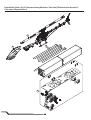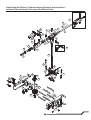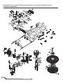
1
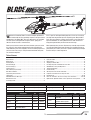
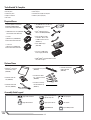
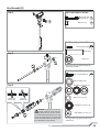
®
Instruction Manual
Bedienungsanleitung
Manuel d’utilisation
Manuale di Istruzioni
®
NOTICE
All instructions, warranties and other collateral documents are subject to change at the sole discretion of Horizon Hobby, Inc. For up-to-date product literature, visit
horizonhobby.com and click on the support tab for this product.
Meaning of Special Language
The following terms are used throughout the product literature to indicate various levels of potential harm when operating this product:
The purpose of safety symbols is to atttract your attention to possible dangers. The safety symbols, and their explanations, deserve your careful attention and
understanding. The safety warnings do not by themselves eliminate any danger. The instructions or warnings they give are not substitutes for proper accident
prevention measures.
NOTICE: Procedures, which if not properly followed, create a possibility of physical property damage AND a little or no possibility of injury.
CAUTION: Procedures, which if not properly followed, create the probability of physical property damage AND a possibility of serious injury.
WARNING: Procedures, which if not properly followed, create the probability of property damage, collateral damage, serious injury or death OR create a high
probability of superficial injury.
Safety Alert: Indicates warning or caution. Attention is required in order to avoid serious personal injury.
WARNING: Read the ENTIRE instruction manual to become familiar with the features of the product before operating. Failure to operate the product correctly
can result in damage to the product, personal property and cause serious injury.
This is a sophisticated hobby product for advanced helicopter pilots with previous experience in the operation of CCPM helicopters (Cyclic Collective Pitch Mixing or
Collective Pitch Helicopter) such as the Blade SR, Blade mCP X or Blade 300 X, and previous kit building experience, such as the Blade 550 X or Blade 600 X. It must
be operated with caution and common sense and requires some basic mechanical ability. Failure to operate this product in a safe and responsible manner could result
in injury or damage to the product or other property. This product is not intended for use by children without direct adult supervision. Do not use with incompatible
components or alter this product in any way outside of the instructions provided by Horizon Hobby, Inc. This manual contains instructions for safety, operation and
maintenance. It is essential to read and follow all the instructions and warnings in the manual, prior to assembly, setup or use, in order to operate correctly and avoid
damage or serious injury.
Age Recommendation: For advanced fliers ages 14 and above. This is not a toy.
General Safety Precautions and Warnings
This model is controlled by a radio signal subject to interference from many sources outside your control. Interference can cause momentary
loss of control.
• Always ensure you fully understand the controls on your transmitter and how they affect the movement of the helicopter.
• Always operate your model outdoors in large, open spaces away from full-size vehicles, traffic and people to avoid collisions or injury
• Always carefully follow the manufacturer’s directions and warnings for any related equipment (i.e., chargers, rechargeable battery packs, etc.).
• Always keep the product, related chemicals, small parts and electrical components out of the reach of children.
• Always keep children out of the vicinity of this product at all times.
• Always store this product well out of the reach of children.
• Always keep hair secured above your shoulders so it cannot get caught in the blades.
• Always avoid water exposure to all equipment not specifically designed and protected for this purpose. Moisture causes damage to electronics.
• Never maintain and operate this product at night, in rain or in inclement weather.
• Always ensure all fasteners are secure before use.
• Always store product in a dry, temperate, secure location
• Do not touch the motor as it can become extremely hot during use.
• Do not fly this helicopter indoors
• Always ensure the failsafe is properly set before flying. Do not exclusively rely on the safety mechanisms built into your transmitter and receiver.
• Always ensure you understand the product and how to operate it.
• Only use Horizon-approved replacement parts and accessories for this product.
• Never place any portion of the model in your mouth as it could cause serious injury.
• Never operate your transmitter or helicopter with low transmitter batteries.
• Never connect the battery unless using or testing the product. Do not perform maintenance with the battery installed.
• Never operate this product if you are tired, ill, taking any medications that impair judgment or are under the influence of alcohol or drugs.
• Never spray glass cleaner or any other liquid on this product.
• Always keep hair and dangling or loose items well away from the blades when the battery is connected.
NOTICE: Modification with non-Horizon-approved components may result in refusal of service by Horizon.
WARNING: This is a large model helicopter with carbon fiber blades that spin at very high RPM. Always use extreme caution and common sense when
maintaining and operating this product. If you are unsure about ANY function or procedure described in this manual, DO NOT operate. Contact Horizon
Product Support for assistance.
WARNING: Always ensure you are operating the helicopter a safe distance, 45 feet (13 meters), away from yourself and others.
EN
2
®
elcome to the world of Blade ® Pro Series helicopter performance.
Over two decades of flying and design experience has gone into the
development of the Blade 700 X. Every part, down to the nuts and bolts,
has been chosen or designed with one goal in mind – giving you a
700-size 3D machine that is second to none.
W
If this is your first helicopter building experience, there are a few things
you might want to get before you start unpacking parts. Many builders
prefer to lay out a towel or a rubber mat to prevent screws from bouncing off the worktable. It’s also a good idea to use small containers to
keep parts organized after you take them out of the bags.
Before you tear into the contents of this box, however, you must review
this manual. It’s been written and designed to make assembling the
Blade 700 X one of the most enjoyable, hassle-free building experiences
you’ll ever have. Every step is clearly illustrated and shows what parts
are needed to complete it.
Most importantly, take your time. Review every assembly step and make
sure you understand how the parts fit before you start bolting things together. When you’re done, you’ll have a capable, smooth-flying helicopter
that flies exactly as it was designed to.
Table of Contents
Tools Needed to Complete ..................................................................................4
Required Items ...................................................................................................4
Optional Items ....................................................................................................4
Assembly Guide ..................................................................................................4
Head Assembly (H) ..............................................................................................5
Frame Assembly (F) ............................................................................................8
Tail Assembly (T) ...............................................................................................14
ESC and Battery Tray Assembly .........................................................................18
Main Rotor Installation ......................................................................................20
Programming Your Transmitter ..........................................................................20
Throttle Hold .....................................................................................................20
AR7200BX Parameter Menu Tips ......................................................................20
Motor Direction Test ..........................................................................................21
Low Voltage Cutoff ............................................................................................21
Flight Guidelines and Warnings .........................................................................21
Flying Your 700X ...............................................................................................21
Blade Tracking ..................................................................................................22
Adjusting the Rudder Gain.................................................................................22
Post Flight Inspection and Maintenance Checklist .............................................22
AR7200BX Fine-Tuning and Adjustment ............................................................22
Troubleshooting Guide ......................................................................................23
Limited Warranty ..............................................................................................24
Warranty and Service Contact Information ........................................................25
Compliance Information for the European Union ................................................25
Exploded Views ......................................................................................... 98-101
Parts List / Ersatzteile / Pièces de rechange / Pezzi di ricambio ............... 102-103
Optional Parts / Optionale Bauteile / Pièces optionnelles / Pezzi opzionali ...........103
Blade 700 X Specifications
Length
53.3 in (1350mm)
Tail Rotor Diameter
Height
15.5 in (395 mm)
Flying Weight
Main Rotor Diameter
64.3 in (1635mm)
Kit
Combo
Motor
E-flite 700 Motor: 520Kv
Component
required
included
ESC
E-flite 100 Amp HV ESC
required
required
Battery
2 x 6S 22.2V 5000mAh 30C +
Li-Po
required
required
Charger
DC Li-Po Balancing Charger
required
required
Main Rotor
Blades
Revolution 690mm FBL 3D
Carbon Main Blades
11–11.6 lb (5,000–5,800 g)
Kit
Combo
Transmitter
DSM2®/DSMX® compatible
transmitter
Component
required
required
Receiver
AR7200BX 7CH DSMX
Flybarless Control System
required
included
Swash Servos Spektrum H6200 (x3)
required
included
Spektrum H6210
required
To register your product online, visit www.bladehelis.com
included
Tail Servo
required
12 in (306mm)
included
3
EN
Tools Needed To Complete
• 1.5mm, 2mm, 2.5mm, 3mm and 4mm hex drivers
• Ball link pliers
• Needle nose pliers
• Phillips screwdriver
• Wire cutter
• Pitch gauge
• Metric calipers
• Petroleum-based, light viscosity lube
• Medium cyanoacrylate (CA)
Required Items
• Receiver/Flybarless control unit
AR7200BX (SPMAR7200BX)
included with combo BLH5725C
• (2X) 5000mAh 6S 22.2V 30C Li-Po,
10AWG with EC5™ connector
(EFLB50006S30)
• DSMX Remote Receiver (SPM9645)
included with combo BLH5725C
• E-flite® EC5 Battery Series
Harness, 10 AWG (EFLAEC508)
• 3 Servos
(3) H6200 servos (SPMSH6200)
included with combo BLH5725C
• E-flite EC5 Device Charge
Lead with 6” Wire & Jacks,
12 AWG and EC5 connector
(EFLAEC512)
• 1 Tail servo
(1) H6210 servo (SPMSH6210)
included with combo BLH5725C
• E-flite 200W charger
(EFLC3020)
• Celectra™ 15VDC 250W
Power Supply (EFLC4010)
• DSM2®/DSMX® compatible DX6i 6 channel
transmitter or higher
Optional Items
• Dynamite® Li-Po Charge
Protection Bag, Large
(DYN1405)
• Control Rod Set Up Tool
(RVO1004)
• Revolution® Ball Link
Tool (RVO1009)
• Revolution Hex Driver
Set, 1.5/2.0/2.5/3.0mm
(RVO2000)
• Revolution Deluxe Ball
Link Pliers (RVO1005)
• Revolution 2.5mm Option Extended Hex Tip
(RVO2012)
• Revolution Low-Bounce
Rubber Work Mat
(RVO1020)
Assembly Guide Legend
Apply BLUE Threadlock
OIL
Apply NO Threadlock
Apply Petroleum-Based,
Light Viscosity Lube
Loosely Tighten
Apply Synthetic Grease
Fully Tighten
Apply MEDIUM CA
EN
4
2X
Repeat Multiple Times
Head Assembly (H)
Step H1
Step H1 parts (bags H1 and H2)
M4 X 25 Cap Head
Shoulder Bolt (x2)
M4 Locknut (x2)
Step H2 parts (bags H1 and H2)
M3 X 10 Cap Head Bolt
Spindle Sleeve
Step H2
Damper (x2)
• Clean the threads in the spindle thoroughly with
alcohol before installation.
Step H3 parts (bag H3)
M4 X 12 Cap Head Bolt (x2)
M4 X 10 X 2 Washer (x2)
Step H3
Smaller inner
diameter (I.D.)
Thrust Bearing, 8 X 16 X 5 (x2)
Washer, 8 X 12.5 X .5 (x2)
Larger inner
diameter (I.D.)
Radial Bearing, 8 X 16 X 5 (x2)
WARNING: Any time you loosen the spindle bolts, completely clean the bolts with
denatured alcohol and ensure you have removed
any residual oil. When putting bolts back on, apply
medium-strength threadlock to the bolts and allow
time for the threadlock (about 4 to 6 hours) to dry
before attempting to fly your helicopter.
5
Stepped Washer, 8 X 16 X 1 (x2)
• The stepped sides of the washers should face the
radial bearings.
EN
Head Assembly cont’d
Step H4 parts (bag H4)
Step H4
A
M3 X 14 Button Head Bolt (x2)
M3 X 12 Button Head Bolt (x2)
Control Ball (x2)
2X
• Loosely install bolts A and B before tightening.
B
Step H5 parts (bag H5)
Step H5
M3x12 Cap Head Bolt (x2)
Washer 3 X 4 X .5 (x4)
Radial Bearing 3 X 6 X 2.5 (x4)
Brass Spacer (x2)
• The stepped sides of the washers should face the
radial bearings.
• Do not over-tighten. The follower arms should move
freely.
2X
EN
6
Head Assembly cont’d
Step H6
Step H6 parts (H6)
M3 X 50 Control Rod (x2)
M3 Ball Link
Pushrod lengths
67mm
Swash to blade grip link (x2)
Anti-Rotation Pin
Control Ball (x7)
7
EN
Frame Assembly (F)
NOTICE: Before assembly, plan your wire routing for the servos. At any point where the servo wire is going to pass through or cross the frame plates,
use sandpaper to round the edge of the frame plate to prevent the wire from chafing.
Step F1 parts (bags F1 and F2)
Step F1
M3 X 8 Cap Head Bolt
(x20)
Washer M3 (x4)
• At this stage of the assembly, do not tighten the
bearing block screws.
• If desired, the swash servos may be installed at this
step, before the bearing blocks are installed into the
frame. Please see step F6 for servo installation parts
and procedure.
Step F2 parts (bag F3)
Step F2
M3 X 14 Cap Head Bolt (x4)
Washer M3 (x4)
EN
8
Frame Assembly cont’d
Step F3
Step F3 parts (bag F4)
One-Way Sleeve
M3 X 6 Button Head Bolts (x6)
• Slide the mainshaft into position, then tighten all the
frame screws.
• A .5mm or 1mm shim may be added above the collar
if needed.
Step F4
Step F4 parts (bag F4)
Frame side
removed for
clarity
M4 X 27 Cap Head Shoulder Bolt
Push down on the main
gear and up on the collar
while tightening the collar
bolts.
9
M4 Lock Nut
M3 X 6 Low Cap Head Bolt (x4)
EN
Frame Assembly cont’d
Step F5 parts (bag F5)
M4 X 40 Cap Head Shoulder Bolt (x3)
Step F5
Head assembly
removed for clarity
M3 X 8 Cap Head Bolt (x4)
M3 Washer (x4)
M4 X 4 Set Screw (x2)
Pinion Helical Mod 1,
13T, 6mm
Step F6 parts (bag F6)
A M3 X 8 Cap Head Bolt (x3)
Step F6
B M3 X 10 Cap Head Bolt (x12)
Aileron servos
M3 Washer (x12)
M2 X 12 Button Head Bolt (x3)
B
M2 Nut (x3)
Servo Control Ball (x3)
Servo Horn (x3)
A
M3 X 55 Control Rod (x3)
M3 Ball Link (x6)
Servo Spacer (x6)
Pushrod lengths
73mm
B
Servo to swash link (x3)
EN
10
Frame Assembly cont’d
Step F6 contd.
Elevator servo
B
Step F7
Step F7 parts (bag F6)
Tail servo
M3 X 16 Cap Head Bolt (x4)
M3 Washer (x4)
Servo Spacer (x2)
Tail Servo Nut (x2)
11
EN
Frame Assembly cont’d
Step F9 parts (bag F7)
Step F9
M3 X 8 Cap Head Bolt (x4)
Step F10 parts (bag F8)
Step F10
Hexagonal Posts (x6)
Jack Shaft
Radial Bearing 12 X 18 X 4 (x2)
Radial Bearing 5 X 10 X 4 (x2)
Gear Pin (x2)
M3 X 4 Set Screw (x2)
EN
12
Frame Assembly cont’d
Step F11
Step F11 parts (bag F8)
M3 X 8 Cap Head Bolt (x12)
Step F12 parts (bag F9)
Step F12
M3 X 8 Cap Head Bolt (x4)
Double-sided
foam tape
AR7200BX Alignment
90°
Front
viewed from top
13
EN
Tail Assembly (T)
Step T1 parts (bag T1)
Step T1
M3 X 6 Button Head Bolt (x2)
Step T2 parts (bag T2)
Step T2
M3 X 4 Set Screw
Gear Pin
Step T3 parts (bag T3)
Step T3
Small inner diameter race
M3 X 8 Cap Head Bolt (x2)
Bearing cage
Control Ball (x2)
M4 X 3 Set Screw
A Washer M3.1 X 7 X .5 (x2)
B Washer M5 X 8 X .5 (x2)
Large inner diameter race
A
B
C
C Washer M8 X 10 X .5 (x2)
Radial Bearing 5 X 10 X 4 (x4)
Thrust Bearing 5 X 10 X 4 (x2)
EN
14
Tail assembly cont’d
Step T4
Step T4 parts (bag T4)
M3 X 6 Button Head Bolt (x2)
Bell Crank Bolt (x2)
Control Ball
Flanged Bearing M3 X 6 X 2.5 (x2)
Washer M3 X 4 X .5 (x2)
viewed from the back
Step T5
Step T5 parts (bag T3)
M3 X 16 Cap Head Shoulder Bolt (x2)
M3 Lock Nut (x2)
15
EN
Tail assembly cont’d
• Glue the torque tube bearings in place by placing a
thin bead of CA on the torque tube at the given locations (278mm, 300mm), then slide the bearings onto
the CA. Do not allow CA to get into the bearings.
Step T6
OIL
OIL
278 mm
Step T7 parts (bags T5 and T6)
Step T7
M3 X 12 Button Head SelfTapping Screw (x3)
M3 X 6 Button Head Bolt (x2)
Ball Link (x2)
Tail Pushrod Guide (x3)
EN
16
300 mm
Tail assembly cont’d
Step T8
Step T8 parts (T7, T8, and T9)
Tail Servo Neutral Position
A M3 X 8 Cap Head Bolt
B M4 X 8 Low Cap Head Bolt
C M3 X 6 Button Head Bolt (x2)
D M3 X 25 Cap Head
Shoulder Bolt (x4)
E M3 X 28 Cap
B
Head Shoulder
Bolt
C
E
M3 Lock Nut (x4)
Tail Servo Horn Install
M3 X 8 Cap
Head Bolt
M2 X 12 Button
Head Bolt
A
D
M2 Nut
Servo Control Ball
• The tail servo horn and
pushrod linkage must be
assembled before mounting
the servo horn. Thread the
ball link onto pushrod, insert
the control ball into the link
and then thread the
2 X 12mm machine screw
through the servo horn and
control ball. Set the tail
servo for the neutral position,
then install the servo horn
onto the servo splines so
the servo horn is 90° to the
pushrod at neutral.
Servo Horn
Step T9 parts (bag T10)
Step T9
B
Hexagonal Post
A M3 X 22 Cap Head Shoulder Bolt
C
B M3 X 16 Cap Head Bolt (x2)
C M3 X 12 Cap Head Bolt
B
M3 Washer (x4)
A
Frame Insert Spacer (x2)
17
EN
ESC and Battery Tray Assembly
Step ESC parts (bag F10)
Hook and loop
strap
Hexagonal Post (x2)
Battery Tray Post (x2)
M3 X 8 Cap Head Bolt (x6)
M2.5 X 6 Counter Sunk Bolt (x2)
M3 X 14 Button Head Bolt (x2)
OR
M3 X 14 Cap Head Bolt (x2)
Canopy Spacer (x2)
Rubber Canopy Standoff (x2)
• The battery tray has forward and rear
mounting locations to accommodate
your equipment selection. Most of the
equipment we’ve used has worked best
with the rear mounting location to achieve
the correct center of gravity. Install both
battery support posts in either the front
or rear location. The front support post
uses a button head screw for the forward
position and a cap head screw for the rear
location to best fit the canopy.
Battery Tray parts (bag B1)
M3 X 8 Counter Sunk Screw (x8)
M4 X 12 Cap Head Bolt (x2)
M2 X 8 Cap Head Screw (x2)
Spacer 4 X 5 X 3 (x2)
Spring (x2)
EN
18
ESC and Battery Tray Assembly cont’d
Loop material
Hook material
Hook and loop
straps
19
EN
Main Rotor Installation
Main Rotor parts (bag H3)
M5 X 28 Cap Head
Shoulder Bolt (x2)
M5 Lock Nut (x2)
• The rotor blades should be tight enough to hold their
position if you hold the helicopter sideways, but loose
enough to swing freely if you move the helicopter
and stop abruptly.
Programming Your Transmitter
Refer to your FBL controller and transmitter manuals for proper setup.
Programming instructions for the E-flite 100-Amp, HV brushless ESC (EFLA2100 ) included with the combo kit can be found online at www.horizonhobby.com. The
EFLA2100 is preprogrammed at the factory. Please use the throttle curves given below for the factory default programming.
Throttle Curve
NORM
ST-1
ST-2
0%
75%
100%
25%
75%
100%
25%
75%
100%
25%
75%
100%
25%
75%
100%
Throttle Hold
When you move the throttle hold switch to the ON position, the helicopter motor
turns off. You will still have control of the helicopter cyclic and rudder commands.
You should also turn throttle hold ON to minimize damage if the helicopter is out
of control or in danger of crashing.
The blades spin if throttle hold is OFF. For safety, turn throttle hold ON any time
you need to touch the helicopter or check the direction controls.
See your transmitter manual for more information on programming throttle hold.
E-flite 100-Amp ESC Throttle Hold Settings
Throttle off,
Throttle off,
no bailout
with bailout (+/–2%)
Throttle on
0
15
Throttle Hold Setting (%)
100
AR7200BX Parameter Menu Tips
Refer to the Spektrum AR7200BX manual to fine tune the Blade 700 X to your
flying and control style via the AR7200BX parameter menu.
If you would like to change the control behavior of the flybarless system to a
pre-defined behavior in the AR7200BX, adjust parameter B (default behavior is
transmitter).
EN
If you would like to have the cyclic behavior to feel more linear OR more like
a flybarred helicopter, increase the cyclic response by adjusting parameter G
(default is ‘normal’).
Refer to the Spektrum AR7200BX manual for specific details on each
parameter.
20
Motor Direction Test
Place the helicopter outdoors on a clean, flat and level surface (concrete or
asphalt) free of obstructions. Always stay clear of moving rotor blades.
3. Connect the Li-Po battery to the ESC.
4. Turn TH HOLD OFF. Slowly increase the throttle until the drive train begins to
turn. The main blades spin clockwise when viewing the helicopter from the top.
The tail rotor blades spin counterclockwise when viewing the helicopter from
the right-hand side.
1. Power on the transmitter. Make sure TH HOLD is ON and the flight mode
switch is in the normal position.
WARNING: The motor will spin when throttle is increased
and TH HOLD is OFF.
NOTICE: If the drive train does not turn with the motor or spins counterclockwise,
turn TH HOLD ON. Disconnect the battery from the helicopter and reverse any
two motor wire connections to the ESC and repeat the motor control test.
2. Lower the throttle completely.
WARNING: Stay at least 45 feet (13 meters) away from
the helicopter when the motor is running.
Low Voltage Cutoff (LVC)
Low voltage cutoff (LVC) protects the Li-Po battery from overdischarge in flight
and activates when the battery reaches 3V per cell under load.
Crash damage and battery damage are not covered under warranty.
Set your transmitter timer for 4 minutes and land when the timer expires.
Repeatedly flying to LVC will damage the flight battery and require you to replace
the battery.
Always disconnect and remove the Li-Po battery from the aircraft after each
flight. Charge your Li-Po battery to about half capacity before storage. During
storage, make sure battery charge does not fall below 3V per cell. A connected
battery will result in trickle discharge.
Flight Guidelines and Warnings
• Always keep moving parts clean.
• Always keep parts dry.
• Always let parts cool after use before touching.
• Always remove batteries after use.
• Always have a first aid kit with you.
• Always have an appropriate fire extinguisher with you.
• Never operate aircraft with damaged wiring.
• Never touch moving parts.
• Always keep aircraft in sight and under control.
• Always keep people and pets at least 45 feet (13 meters) away when the
battery is connected.
• Keep children out of the vicinity of this product at all times.
• Always turn on throttle hold at rotor strike.
• Always use fullly charged batteries.
• Always keep transmitter powered on while aircraft is powered.
• Always remove batteries before disassembly.
Flying Your 700 X
CAUTION: Always fly the helicopter with your back to the sun and wind to
prevent loss of flight control.
Consult local laws and ordinances before choosing a location
to fly your aircraft.
Select a large, open area away from people and objects. Your first flights should
be outdoors in low-wind conditions. Always stay at least 45 feet
(13 meters) away from the helicopter when it is flying.
Do not attempt to fly the Blade 700 X indoors.
CAUTION: The Blade 700 X is intended for pilots with experience flying
aerobatic, collective pitch helicopters. The Blade 700 X is more responsive
than other Blade helicopters. If you are not an experienced 3D or collective pitch
helicopter pilot, do not attempt to fly this product.
Takeoff
Gradually increase the throttle, allowing the rotors time to come up to speed.
CAUTION: Do not give any aileron, elevator or rudder commands before the
helicopter lifts off. Any control inputs prior to liftoff could cause a crash.
The helicopter will lift off the ground when the rotor head reaches a suitable
speed and you apply collective pitch. Once airborne, establish a low-level hover
to verify everything is functioning properly. DO NOT use trim to assist in holding
the Blade 700X in a desired position. The AR7200BX Flybarless Stabilization
System renders trim unnecessary by working to keep the helicopter in whatever
attitude you command with the control sticks.
Flying
This aircraft is extremely sensitive to control inputs. We recommend you fly at
low rate settings for the first few flights until you are familiar with its response.
For pilots new to collective pitch helicopters, familiarize yourself with your Blade
700 X in normal mode and at low rate.
21
Landing
Establish a low level hover. Deliberately lower the throttle until the helicopter
lands. Make only small control corrections during this time to avoid rotor blade
strikes or other damage.
When the helicopter is in stunt mode:
• The rotor head speed is constant.
• The main rotor will increase negative pitch as the throttle/collective stick is
moved from the middle stick position to the low stick position. Negative pitch
allows the helicopter to fly upside down and perform aerobatics.
Change between stunt and normal modes in a hover with the throttle near the
hovering stick position.
The helicopter may go up or down when you change between modes due to the
difference in the throttle and pitch curves.
NOTICE: To minimize damage, always activate throttle hold in preparation for or
during a crash.
WARNING: Only use Blade 700 X approved carbon fiber main blades.
Do not use wooden main blades with the Blade 700 X. Using wooden
main blades may cause injury or property damage.
As you become more familiar with the helicopter’s response, adjust the rates,
expo, pitch and throttle curves to suit your flying style.
EN
Blade Tracking
WARNING: Always maintain a safe distance of at least 13 meters
(45 feet) when checking the main rotor blade tracking.
To check the blade tracking:
1. Put the helicopter in a hover at an altitude near eye height.
2. Watch the movement at the blade tips. Both blades should travel in the
same plane.
3. If one blade tip appears to be higher than the other, land the helicopter,
disconnect the flight battery and adjust the blade linkages.
4. Repeat Steps 1 through 3 until both blades are moving in the same plane.
Adjusting the Rudder Gyro Gain
• If the tail wags or oscillates, lower the gain on the gyro.
• If the tail is drifting while hovering, increase the gain on the gyro.
On your transmitter’s gyro menu, decrease the gyro gain values a small amount
at a time until the helicopter is stable within a particular flight mode
On your transmitter, increase the gyro gain values a small amount at a time until
the tail starts to wag/oscillate. Afterwards, reduce the gain until the tail stops
wagging/oscillating within a particular flight mode.
Post-Flight Inspection and Maintenance Checklist
√
√
Ball Links
Make sure the plastic ball link holds the control ball, but
is not tight (binding) on the ball. When a link is too loose
on the ball, it can separate from the ball during flight and
cause a crash. Replace worn ball links before they fail.
Cleaning
Make sure the battery is not connected before cleaning.
Remove dust and debris with a soft brush or a dry lint-free
cloth.
Bearings
Replace bearings when they become notchy (sticky in
places when turning) or draggy.
Wiring
Make sure wiring does not block moving parts. Replace
damaged wiring and loose connectors.
Fasteners
Make sure there are no loose screws, other fasteners or
connectors. Do not over tighten metal screws in plastic
parts. Tighten screw so parts are mated together, then turn
screw only 1/8th of a turn more.
Rotors
Make sure there is no damage to rotor blades and other
parts which move at high speed. Damage to these parts
includes cracks, burrs, chips or scratches. Replace damaged parts before flying.
Gyro
Make sure the AR7200BX is securely attached to the
frame. Replace the double-sided tape when necessary. The
helicopter will crash if the AR7200BX separates from the
helicopter frame.
Gearing
Make sure the gears are all in good condition. Watch for
chipped teeth or excessive wear. White dust around gears
is an indication of excess wear. Replace damaged gears
before flying.
AR7200BX Fine-tuning and Adjustment
Observed Behavior
Cyclic response is too slow or too fast
Suggested Adjustment
Adjust end points to fit your flying style. Refer to your transmitter instruction
manual for more information
Adjust the control behavior parameter in the AR7200BX to fit your flying style.
Control inputs feel delayed
Increase Dial 2 on the AR7200BX
The helicopter seems to overshoot control input and then return
Decrease Dial 2 on the AR7200BX
The helicopter tail stops too abruptly
Decrease Dial 3 on the AR7200BX
The helicopter tail does not stop precisely
Increase the rudder gain in your transmitter
Increase Dial 3 on the AR7200BX
Adjust the rudder heading lock gain parameter in the AR7200BX
EN
22
Blade 700 X Troubleshooting Guide
Problem
AR7200BX will not initialize
Possible Cause
Solution
The helicopter was moved during initialization
Lay the helicopter on its side during initialization if windy
The transmitter is powered off
Power on the transmitter
Center elevator, aileron and rudder controls. Make sure the throttle
Controls are not centered
is at idle
Power off transmitter, move transmitter a larger distance from airTransmitter is too near aircraft during binding process craft, disconnect and reconnect flight battery to aircraft and follow
binding instructions
LED on receiver flashes rapidly and
aircraft will not bind to transmitter
Bind switch or button was not held while transmitter
Power off transmitter and repeat bind process
(during binding)
was powered on
Aircraft or transmitter is too close to large metal ob- Move aircraft and transmitter to another location and attempt binding
ject, wireless source or another transmitter
again
Less than a 5-second wait between first powering on Leaving transmitter on, disconnect and reconnect flight battery to
transmitter and connecting flight battery to aircraft
aircraft
Aircraft is bound to a different model memory
Select correct model memory on transmitter and disconnect and reconnect flight battery to aircraft
LED on receiver flashes rapidly and (ModelMatchTM radios only)
aircraft will not respond to transmit- Flight battery/transmitter battery charge is too low
Replace/recharge batteries
ter (after binding)
Transmitter may have been bound to a different model
Select the right transmitter or bind to the new one
(or with a different DSM Protocol)
Aircraft or transmitter is too close to large metal ob- Move aircraft and transmitter to another location and attempt conject, wireless source or another transmitter
necting again
Throttle not at idle and/or throttle trim is too high
Lower the throttle stick and lower the throttle trim
Helicopter will not respond to the
throttle but responds to other controls
Helicopter power is lacking
Helicopter will not lift off
The helicopter tail spins out of
control
The helicopter wobbles in flight
The transmitter is not in normal mode or throttle hold
is on
Make sure the transmitter is in normal mode and throttle hold is off
The motor is not connected to the ESC or the motor
wires are damaged
Connect the motor wires to the ESC and check motor wires for damage
Flight battery charge is too low
Replace or recharge flight battery
Throttle channel is reversed
Reverse the throttle channel on the transmitter
Flight battery has low voltage
Fully charge the flight battery
Flight battery is old or damaged
Replace the flight battery
Flight battery cells are unbalanced
Fully charge the flight battery, allowing the charger time to balance
the cells
Transmitter settings are not correct
Check throttle and pitch curve settings and pitch control direction
Flight battery has low voltage
Fully charge the flight battery
Main rotor blades are installed backwards
Install the main rotor blades with the thicker side as the leading
edge
Rudder control and/or sensor direction reversed
Make sure the rudder control and the rudder sensor are operating in
the correct direction
Tail servo is damaged
Check the rudder servo for damage and replace if necessary
Tail drive gears are damaged
Replace damaged gears.
Inadequate control arm throw
Check the rudder control arm for adequate travel and adjust if necessary
Torque tube is not fully engaged in tail gears.
Ensure the tail boom and tail gear box are fully seated. Confirm tail
pushrod length and tail settings on AR7200BX are correct after making any changes.
Cyclic gain is too high
Decrease Dial 1 on the AR7200BX
Headspeed is too low
Increase the helicopter's head speed via your transmitter settings
and/or using a freshly charged flight pack
Dampers are worn
Replace the main rotor head dampers
23
EN
Limited Warranty
What this Warranty Covers
Horizon Hobby, Inc., (Horizon) warrants to the original purchaser that the product
purchased (the “Product”) will be free from defects in materials and workmanship at
the date of purchase.
What is Not Covered
This warranty is not transferable and does not cover (i) cosmetic damage, (ii)
damage due to acts of God, accident, misuse, abuse, negligence, commercial use, or
due to improper use, installation, operation or maintenance, (iii) modification of or to
any part of the Product, (iv) attempted service by anyone other than a Horizon Hobby
authorized service center, (v) Product not purchased from an authorized Horizon
dealer, or (vi) Product not compliant with applicable technical regulations.
OTHER THAN THE EXPRESS WARRANTY ABOVE, HORIZON MAKES NO OTHER
WARRANTY OR REPRESENTATION, AND HEREBY DISCLAIMS ANY AND ALL IMPLIED
WARRANTIES, INCLUDING, WITHOUT LIMITATION, THE IMPLIED WARRANTIES
OF NON-INFRINGEMENT, MERCHANTABILITY AND FITNESS FOR A PARTICULAR
PURPOSE. THE PURCHASER ACKNOWLEDGES THAT THEY ALONE HAVE
DETERMINED THAT THE PRODUCT WILL SUITABLY MEET THE REQUIREMENTS OF
THE PURCHASER’S INTENDED USE.
Purchaser’s Remedy
Horizon’s sole obligation and purchaser’s sole and exclusive remedy shall be that
Horizon will, at its option, either (i) service, or (ii) replace, any Product determined by
Horizon to be defective. Horizon reserves the right to inspect any and all Product(s)
involved in a warranty claim. Service or replacement decisions are at the sole
discretion of Horizon. Proof of purchase is required for all warranty claims. SERVICE
OR REPLACEMENT AS PROVIDED UNDER THIS WARRANTY IS THE PURCHASER’S
SOLE AND EXCLUSIVE REMEDY.
Limitation of Liability
HORIZON SHALL NOT BE LIABLE FOR SPECIAL, INDIRECT, INCIDENTAL OR
CONSEQUENTIAL DAMAGES, LOSS OF PROFITS OR PRODUCTION OR COMMERCIAL
LOSS IN ANY WAY, REGARDLESS OF WHETHER SUCH CLAIM IS BASED IN
CONTRACT, WARRANTY, TORT, NEGLIGENCE, STRICT LIABILITY OR ANY OTHER
THEORY OF LIABILITY, EVEN IF HORIZON HAS BEEN ADVISED OF THE POSSIBILITY
OF SUCH DAMAGES. Further, in no event shall the liability of Horizon exceed the
individual price of the Product on which liability is asserted. As Horizon has no
control over use, setup, final assembly, modification or misuse, no liability shall be
assumed nor accepted for any resulting damage or injury. By the act of use, setup or
assembly, the user accepts all resulting liability. If you as the purchaser or user are
not prepared to accept the liability associated with the use of the Product, purchaser
is advised to return the Product immediately in new and unused condition to the
place of purchase.
Law
These terms are governed by Illinois law (without regard to conflict of law principals).
This warranty gives you specific legal rights, and you may also have other rights
which vary from state to state. Horizon reserves the right to change or modify this
warranty at any time without notice.
WARRANTY SERVICES
Questions, Assistance, and Services
Your local hobby store and/or place of purchase cannot provide warranty support
or service. Once assembly, setup or use of the Product has been started, you
must contact your local distributor or Horizon directly. This will enable Horizon
to better answer your questions and service you in the event that you may need
any assistance. For questions or assistance, please visit our website at www.
horizonhobby.com, submit a Product Support Inquiry, or call the toll free telephone
number referenced in the Warranty and Service Contact Information section to speak
with a Product Support representative.
EN
Inspection or Services
If this Product needs to be inspected or serviced and is compliant in the country
you live and use the Product in, please use the Horizon Online Service Request
submission process found on our website or call Horizon to obtain a Return
Merchandise Authorization (RMA) number. Pack the Product securely using a
shipping carton. Please note that original boxes may be included, but are not
designed to withstand the rigors of shipping without additional protection. Ship via a
carrier that provides tracking and insurance for lost or damaged parcels, as Horizon
is not responsible for merchandise until it arrives and is accepted at our facility.
An Online Service Request is available at http://www.horizonhobby.com/content/_
service-center_render-service-center. If you do not have internet access, please
contact Horizon Product Support to obtain a RMA number along with instructions
for submitting your product for service. When calling Horizon, you will be asked to
provide your complete name, street address, email address and phone number
where you can be reached during business hours. When sending product into
Horizon, please include your RMA number, a list of the included items, and a brief
summary of the problem. A copy of your original sales receipt must be included for
warranty consideration. Be sure your name, address, and RMA number are clearly
written on the outside of the shipping carton.
NOTICE: Do not ship LiPo batteries to Horizon. If you have any issue with a LiPo
battery, please contact the appropriate Horizon Product Support office.
Warranty Requirements
For Warranty consideration, you must include your original sales receipt
verifying the proof-of-purchase date. Provided warranty conditions have been
met, your Product will be serviced or replaced free of charge. Service or replacement
decisions are at the sole discretion of Horizon.
Non-Warranty Service
Should your service not be covered by warranty, service will be completed
and payment will be required without notification or estimate of the
expense unless the expense exceeds 50% of the retail purchase cost. By
submitting the item for service you are agreeing to payment of the service without
notification. Service estimates are available upon request. You must include this
request with your item submitted for service. Non-warranty service estimates will be
billed a minimum of ½ hour of labor. In addition you will be billed for return freight.
Horizon accepts money orders and cashier’s checks, as well as Visa, MasterCard,
American Express, and Discover cards. By submitting any item to Horizon for service,
you are agreeing to Horizon’s Terms and Conditions found on our website http://
www.horizonhobby.com/content/_service-center_render-service-center.
ATTENTION: Horizon service is limited to Product compliant in the country
of use and ownership. If received, a non-compliant Product will not be
serviced. Further, the sender will be responsible for arranging return
shipment of the un-serviced Product, through a carrier of the sender’s
choice and at the sender’s expense. Horizon will hold non-compliant
Product for a period of 60 days from notification, after which it will be
discarded.
24
Warranty and Service Contact Information
Country of Purchase
Horizon Hobby
Contact Information
Address
Horizon Service Center
servicecenter.horizonhobby.com/RequestForm/
(Repairs and Repair Requests)
www.quickbase.com/db/
Horizon Product Support
United States of America (Product Technical Assistance) bghj7ey8c?a=GenNewRecord
888-959-2304
Sales
[email protected]
888-959-2304
Service/Parts/Sales:
Horizon Hobby Limited
[email protected]
Horizon Technischer Service
[email protected]
Sales: Horizon Hobby GmbH
+49 (0) 4121 2655 100
France
Service/Parts/Sales:
Horizon Hobby SAS
[email protected]
China
Service/Parts/Sales:
Horizon Hobby – China
[email protected]
United Kingdom
Germany
4105 Fieldstone Rd
Champaign, Illinois, 61822 USA
+44 (0) 1279 641 097
+33 (0) 1 60 18 34 90
+86 (021) 5180 9868
Units 1–4 , Ployters Rd, Staple Tye
Harlow, Essex, CM18 7NS, United Kingdom
Christian-Junge-Straße 1
25337 Elmshorn, Germany
11 Rue Georges Charpak
77127 Lieusaint, France
Room 506, No. 97 Changshou Rd.
Shanghai, China 200060
Compliance Information for the European Union
Declaration of Conformity
(in accordance with ISO/IEC 17050-1)
No. HH2013072101
Product(s):
Blade 700 X Pro Series Combo
Item Number(s):
BLH5725C
The object of declaration described above is in conformity with the requirements of the specifications
listed below, following the provisions of the European R&TTE Directive 1999/5/EC and European EMC
Directive 2004/108/EC:
EN 301 489-1 V1.9.2: 2012
EN301 489-17 V2.1.1: 2009
EN55022:2010 + AC:2011
EN55024:2010
Signed for and on behalf of:
Horizon Hobby, Inc.
Champaign, IL USA
July 21, 2013
Robert Peak
Chief Financial Officer
Horizon Hobby, Inc.
Instructions for disposal of WEEE by users in the European Union
This product must not be disposed of with other waste. Instead, it is the user’s responsibility to dispose of their waste equipment by handing it over to a
designated collections point for the recycling of waste electrical and electronic equipment. The separate collection and recycling of your waste equipment at the time of disposal will help to conserve natural resources and ensure that it is recycled in a manner that protects human health and the environment. For more information about where you can drop off your waste equipment for recycling, please contact your local city office, your household
waste disposal service or where you purchased the product.
25
EN
Exploded View (Battery Tray) / Explosionszeichnung Akkuhalter / Vue éclatée (Platine de fixation de batterie) /
Vista esplosa (Supporto batteria)
73
71
20
58
98
Exploded View (Head/Tailcase) / Explosionszeichnung (Rotorkopf / Heckrotorgehäuse) /
Vue éclatée (Tête et Anticouple) / Vista esplosa (Testa/Scatola di coda)
2x
1
5
8
30
3
5
6
3
9
2
6
65
4
3
5
2x
67
8
65
4
14
3
7
12
13
13
70
35
7
37
15
35
38
39
42
69
37
75
70
35
35
99
Exploded View (Frame Assembly) / Explosionszeichnung (Chassis) / Vue éclatée (Assemblage du châssis) /
Vista esplosa (Gruppo telaio)
78
27
31
34
59
22
25
59
28
59
22
28
26
26
36
59
76
26
29
19
26
18
26
77
11
23
16
32
61 62
63 64
10
11
33
24
17
18
14
10
14
100
Exploded View (Tailboom Assembly) / Explosionszeichnung (Heckausleger) / Vue éclatée (Assemblage de la poutre) /
Vista esplosa (Gruppo tubo coda)
50
45
47
46
49
44
47
43
43
70
48
47
54
41
68
40
70
40
39
52
53
55
54
51
56
70
101
57
Parts List / Ersatzteile / Pièces de rechange / Pezzi di ricambio
#
Part #
English
Deutsch
Français
1
BLH5701
Main Rotor Grip Set: 700 X
Blade 700 X: Rotorblatthalterset
2
BLH5702
Main Grip Arms: 700 X
Blade 700 X: Rotorblatthalterarmset
3
BLH5703
Spindle Set (2): 700 X
Blade 700 X: Blatthalterwelle (2)
4
BLH5704
Main Rotor Blade Bolt Set (2): 700 X
Blade 700 X: Rotorblattbolzen (2)
5
6
BLH5705
BLH5706
Dampers (4): 700 X
Head Block: 700 X
Blade 700 X: Dämpfer (4)
Blade 700 X: Rotorblockkopf
700 X - Pieds de pales principales
700 X - Leviers de pieds de pales
principales
700 X - Axe de pieds de pales (2)
700 X - Vis de fixations de pales
principales (2)
700 X - Amortisseurs (4)
700 X - Moyeu de tête
7
BLH5707
Main Rotor Head Link Set: 700 X
Blade 700 X: Anlenkungen Hauptrotorkopf
700 X - Set de tringleries de tête rotor
8
9
10
11
12
BLH5708
BLH5709
BLH5710
BLH5711
BLH5712
Follower Arms: 700 X
Radius Arms: 700 X
Servo Control Arm Set: 700 X
Servo Control Link Set
Aluminum Swashplate: 700 X
13 BLH5713
Swashplate Ball Set: 700 X
14 BLH5714
Main Shaft (2): 700 X
Blade 700 X: Taumelscheibenmitnehmer
Blade 700 X: Pitchkompensator
Blade 700 X: Servoarm Set
Blade 700 X: Servonanlenkungen Set
Blade 700 X: Aluminium Taumelscheibe
Blade 700 X: Kugelköpfe Taumelscheibe
Set
Blade 700 X: Hauptrotorwelle
15 BLH5715
Main Shaft Retaining Collar: 700 X
Blade 700 X: Stellring f. Hauptrotorwelle
16 BLH5716
17 BLH5717
Blade 700 X: Hauptzahnrad (2)
Blade 700 X: Autorotationsfreilauf (2)
18 BLH5718
Main Gear (2): 700 X
Autorotation Gear (2): 700 X
One-Way Bearing Hub w/One way
bearing: 700 X
Blade 700 X: Freilauflager
700 X - Bras flybarless
700 X - Bras radiaux
700 X - Set de bras de servo
700 X - Set de tringleries de servo
700 X - Plateau cyclique en aluminium
700 X - Set de rotules de plateau
cyclique
700 X - Axe principal (2)
700 X - Bague de retenue de l’axe
principal
700 X - Couronne principale (2)
700 X - Couronne d’autorotation (2)
700 X - Moyeu de roue libre avec
roue libre
19 BLH5719
One-Way Bearing Sleeve: 700 X
Blade 700 X: Freilaufbuchse
700 X - Axe de roue libre
20 BLH5720
Stock Canopy: 700 X
Blade 700 X: Kabinenhaube
21 BLH5721
Canopy Grommets: 700 X
Blade 700 X: Kabinenhaubenhalter
22 BLH5722
CF Main Frame (1) L or R: 700 X
Blade 700 X: Chassis (1) Links o. Rechts
23
24
25
26
27
28
29
30
31
32
33
Upper Bearing Block: 700 X
Bottom Servo Mount : 700 X
Lower Bearing Block: 700 X
Servo Screw Set: 700 X
ESC Mounting Tray: 700 X
Landing Gear Mounts: 700 X
Landing Gear Set: 700 X
Ball Link Set: 700 X
Anti-Rotation Bracket: 700 X
Motor Mount: 700 X
Pinion Support: 700 X
Blade 700 X: Lagerblock oben
Blade 700 X: Servohalter unten
Blade 700 X: Lagerblock unten
Blade 700 X: Servoschraubenset
Blade 700 X: Halter f. Regler
Blade 700 X: Kufenhalter
Blade 700 X: Kufengestell
Blade 700 X: Kugelkopfset
Blade 700 X: Taumelscheibenführung
Blade 700 X: Motorhalter
Blade 700 X: Ritzelhalter
34 BLH5735
FBL Unit Mount: 700 X
Blade 700 X: FBL Einheit Halter
35
36
37
38
39
Fr Tail Boom Case: 700 X
Canopy Posts: 700 X
Tail Pinion Gear-27T: 700 X
Bevel Gear-25T: 700 X
Bevel Gear-24T: 700 X
Blade 700 X: Heckrotorgehäuse vorne
Blade 700 X: Kabinenhaubenstreben
Blade 700 X: Heckrotorritzel
Blade 700 X: Kegelrad 25T
Blade 700 X: Kegelrad 24T
40 BLH5741
Tail Shaft Bevel Gear-24T: 700 X
Blade 700 X: Kegelrad Heckrotorwelle
41 BLH5742
Tail Shaft: 700 X
Blade 700 X: Heckrotorblattwelle
42 BLH5743
Tail Pinion Shaft: 700 X
Blade 700 X: Welle f. Heckrotorritzel
43 BLH5744
44 BLH5745
Boom Support Set: 700 X
Boom (2): 700 X
Blade 700 X: Halter Heckausleger
Blade 700 X: Heckausleger (2)
45 BLH5746
Torque Tube Assembly: 700 X
Blade 700 X: Heckwelle
46 BLH5747
Torque Tube Holder: 700 X
Blade 700 X: Halter f. Heckwelle
47 BLH5748
Tail Pushrod Set (2): 700 X
Blade 700 X: Gestänge
48 BLH5749
Tail Pushrod Guide Set: 700 X
Blade 700 X: Gestängeführung Heck
49 BLH5750
Horizontal Fin Mount: 700 X
Blade 700 X: Halter f. Heckfinne
700 X - Bulle d’origine
700 X - Caoutchoucs de fixation de
bulle
700 X - Flanc de châssis en carbone
(1) G ou D
700 X - Palier supérieur
700 X - Support inférieur de servo
700 X - Palier inférieur
700 X - Set de vis de servo
700 X - Platine de fixation de contrôleur
700 X - Fixations de train d’atterrissage
700 X - Train d’atterrissage
700 X - Set de rotules
700 X - Guide anti-rotation
700 X - Support moteur
700 X - Support de pignon
700 X - Support de mode de contrôle
flybarless
700 X - Support de poutre de queue
700 X - Supports de bulle
700 X - Pignon d’anticouple 27T
700 X - Pignon conique 25T
700 X - Pignon conique 24T
700 X - Pignon conique d’axe d’anticouple 24T
700 X - Axe d’anticouple
700 X - Axe d’entraînement d’anticouple
700 X - Renforts de poutre de queue
700 X - Poutre de queue (2)
700 X - Arbre de transmission
d’anticouple
700 X - Support d’arbre de transmission
700 X - Set de commande d’anticouple
(2)
700 X - Guides de commande
d’anticouple
700 X - Support de stabilisateur
BLH5723
BLH5724
BLH5726
BLH5727
BLH5728
BLH5729
BLH5730
BLH5731
BLH5732
BLH5733
BLH5734
BLH5736
BLH5737
BLH5738
BLH5739
BLH5740
102
Italiano
Set portapale rotore principale: 700 X
Braccetti portapale: 700 X
Set alberino: 700 X
Set viti pala rotore principale: 700 X
Smorzatori: 700 X
Blocco testa: 700 X
Set collegamenti testa rotore principale:
700 X
Bracci inseguitore: 700 X
Braccetti testa: 700 X
Set bracci controllo servo: 700 X
Set comandi servo: 700 X
Piatto oscillante alluminio: 700 X
Set sfere piatto: 700 X
Albero principale: 700 X
Collare albero principale: 700 X
Ingranaggio principale: 700 X
Ingranaggio autorotazione: 700 X
Cuscinetto unidirezionale c/supporto:
700 X
Manicotto cuscinetto unidirezionale:
700 X
Capottina di serie: 700 X
Gommini capottina: 700 X
CF Telaio principale (1) L o R: 700 X
Cuscinetto superiore blocco: 700 X
Supporto inferiore servo: 700 X
Cuscinetto inferiore blocco: 700 X
Set viti servo: 700 X
Supporto ESC: 700 X
Supporti carrello: 700 X
Set carrello: 700 X
Set sfere comandi: 700 X
Staffa anti rotazione: 700 X
Supporto motore: 700 X
Supporto pignone: 700 X
Supporto unità FBL: 700 X
Scatola coda: 700 X
Appoggi capottina: 700 X
Pignone coda: 700 X
Ingranaggio conico 25T: 700 X
Ingranaggio conico 24T: 700 X
Ingranaggio conico albero coda: 700 X
Albero coda: 700 X
Pignone albero coda: 700 X
Set supporto tubo coda: 700 X
Tubo coda: 700 X
Gruppo barra di torsione: 700 X
Supporto barra di torsione: 700 X
Set comandi coda: 700 X
Set guida comandi coda: 700 X
Supporto impennaggio orizzontale: 700 X
#
Part #
50 BLH5751
51 BLH5752
52 BLH5753
53
54
55
56
57
58
BLH5754
BLH5755
BLH5756
BLH5757
BLH5758
BLH5759
English
Deutsch
Français
Italiano
Fin Set: 700 X
Tail Rotor Pitch Lever Set: 700 X
Tail Rotor Pitch Control Slider Set:
700 X
Tail Pitch Slider Yolk: 700 X
Tail Rotor Hub: 700 X
Tail Rotor Blade Grip: 700 X
Tail Bellcrank Mount: 700 X
Tail Case Set: 700 X
Battery Tray: 700 X
Blade 700 X: Finnenset
Blade 700 X: Heckrotorpitchhebelset
700 X - Set d’empennages
700 X - Levier de pas d’anticouple
Set impennaggio: 700 X
Set leve passo rotore coda: 700 X
Blade 700 X: Schiebehülse Heckrotor Set
700 X - Coulisseau d’anticouple
Set cursore controllo passo coda: 700 X
Blade 700X : Heckumlenkhebel
Blade 700 X: Heckrotorzentralstück
Blade 700 X: Heckrotorblatthalter
Blade 700 X: Halter Heckrotorwinkelhebel
Blade 700 X: Heckrotorgehäuse
Blade 700 X: Akkuträger
700 X - Fourchette de coulisseau
700 X - Moyeu d’anticouple
700 X - Pieds de pales d’anticouple
700 X - Support de levier d’anticouple
700 X - Boîtier d’anticouple
700 X - Platine de fixation de batterie
700 X - Supports de platine porte
batterie
700 X - Support de verrouillage de la
batterie
700 X - Pignon 12T
700 X - Pignon 13T
700 X - Pignon 14T
700 X - Pignon 15T
Roulement 8x16x5mm
Roulement 12x24x6mm
Butée à billes 8x16x5mm
Butée à billes 5x10x4mm
Roulement 12x18x4mm
Roulement 5x10x4mm
700 X - Sangle auto-agrippante
Pales d’anticouple 3D en carbone
115mm
Pales principales FBL 3D en carbone
690mm
700 X - Support des pales principales
700 X - Set de visserie
Goupilles d’entraînement de pignons
Inserts de châssis en caoutchouc
Moteur brushless 700 Héli à cage
tournante 520kv
Contrôleur brushless 100A HV
Programmateur de contrôleur HV
Centrale cursore passo coda: 700 X
Mozzo rotore coda: 700 X
Porta pale rotore coda: 700 X
Supporto squadretta coda: 700 X
Set scatola coda: 700 X
Supporto batteria: 700 X
Appoggi montaggio supporto batteria:
700 X
59 BLH5760
Battery Tray Mounting Posts: 700 X
60 BLH5761
72 RVOT011500
Snap Battery Tray Locking Mount:
700 X
Pinion 12T: 700 X
Pinion 13T: 700 X
Pinion 14T: 700 X
Pinion 15T: 700 X
8x16x5mm Radial Bearing
12x24x6mm Radial Bearing
8x16x5mm Thrust Bearing
5x10x4mm Thrust Bearing
12x18x4mm Radial Bearing
5x10x4mm Radial Bearing
Hook and Loop Battery Strap: 700 X
115mm Carbon Fiber 3D Tail Rotor
Blades
73 RVOB069050
690mm FBL 3D Carbon Main Blades
BLH5771
74 BLH5772
75 BLH5773
76 BLH5774
Helicopter Main Blade Holder: 700 X
Hardware Set: 700 X
Gear Pins
Rubber Frame Inserts
Heli 700 Brushless Outrunner Motor,
520Kv
100-Amp HV Brushless ESC
HV Speed Control Programmer
61
62
63
64
65
66
67
68
69
70
71
BLH5762
BLH5763
BLH5764
BLH5765
BLH5766
BLH5767
BLH5768
BLH5769
BLH5561
BLH1642
BLH5770
77 EFLM60700B
78 EFLA2100
EFLA108
Blade 700 X: Stützen Akkuhalter
Blade 700 X: Akkuverschluss
Blade 700 X: Ritzel 12T
Blade 700 X: Ritzel 13T
Blade 700 X: Ritzel 14T
Blade 700 X: Ritzel 15T
Blade 700 X: 8x16x5mm Radiallager
Blade 700 X: 12x24x6mm Radiallager
Blade 700 X: 8x16x5mm Drucklager
Blade 700 X: 5x10x4mm Drucklager
Blade 700 X: 12x18x4mm Radiallager
Blade 700 X: 5x10x4mm Radiallager
Blade 700 X: Klettschlaufe
Revolution 115mm Carbon Fiber 3D
Heckrotorblätter
Revolution 690mm FBL 3D Carbon
Hauptrotorblatt
Blade 700 X: Blatthalter
Blade 700 X: Kleinteile
Blade Ritzelsplint
Blade Gummieinsätze
E-flite Heli 700 Brushless AussenläuferMotor , 520Kv
E-flite 100-Amp HV Brushless ESC / Regler
HV Speed Control Programmierkarte
Aggancio supporto batteria: 700 X
Pignone 12T: 700 X
Pignone 13T: 700 X
Pignone 14T: 700 X
Pignone 15T: 700 X
8x16x5mm Cuscinetto radiale
12x24x6mm Cuscinetto radiale
8x16x5mm Cuscinetto radiale
5x10x4mm Cuscinetto radiale
12x18x4mm Cuscinetto radiale
5x10x4mm Cuscinetto radiale
Fascetta a strappo per batteria: 700X
115mm Pale coda in carbonio per 3D
690mm Pale principali in carbonio per
3D e FBL
Supporto pala principale heli: 700 X
Set viteria: 700 X
Perni ingranaggio
Inserti telaio in gomma
Heli 700 motore a cassa rotante
brushless 520Kv
100-Amp Regolatore (ESC) brushless
HV Programmatore x regolatore velocità
Optional Parts / Optionale Bauteile / Pièces optionnelles / Pezzi opzionali
Part #
English
Deutsch
Français
Italiano
BLH5730B
Blade 700 X: Kufengestell schwarz
Blade 700 X: Freilauf
BLH5775
Black Landing Gear: 700 X
One-Way Bearing Hub w/Sprague
bearing: 700 X
3-Blade Head Conversion: 700 X
Carrello atterraggio nero: 700 X
Mozzo cuscinetto unidirezionale con ruota
libera: 700 X
Conversione testa a 3 pale: 700 X
BLH5776
3-Blade Head Spindle (3): 700 X
Blade 700X : 3-Blattlagerwelle
BLH5777
3-Blade Head Block: 700 X
Blade 700X : 3 Blattrotorkopf
BLH5735A
Metal FBL Unit Mount: 700 X”
Blade 700X : Metallhalter FBL Einheit
700 X - Train d’atterrissage noir
700 X - Moyeu de roue libre avec roue
libre à cames
700 x - Conversion tripale
700 X - Axes de pieds de pales pour
conversion tripale (3)
700 X - Moyeu de tête pour conversion
tripale
700 X - Support en métal de module de
contrôle FBL
Supporto metallo per unità FBL: 700 X”
BLH5732A
Metal Anti-Rotation Bracket: 700 X
Blade 700X : Metall Taumelscheibenführung
700 X - Guide anti-rotation en métal
Staffa in metallo anti rotazione: 700 X
BLH5778
Metal Tail Servo Bracket: 700X
Blade 700X : Metall Heckservohalter
700 X - Support de servo d’anticouple
en métal
Staffa in metallo servo coda: 700X
BLH5752A
Metal Tail Rotor Pitch Lever Set:
700 X
710mm FBL 3D Carbon Main
Blades
H6200 HV Digital High Speed Heli
Cyclic MG Servo
H6210 HV Digital Ultra Speed Heli
Tail MG Servo
Blade 700 X: Metall Heckrotorpitchhebelset
Revolution 710mm FBL 3D Carbon
Hauptrotorblatt
Spektrum H6200 HV Digital Hi Speed
Heli Taumelscheibenservo MG
Spektrum H6210 HV Digital Ultra
Speed Heli Heckservo MG
700 X - Levier d’anticouple en métal
Set leve in metallo per passo rototre:
700 X
710mm Pale principali in carbonio per
3D e FBL
H6200 HV Servo digitale MG, alta velocità
per ciclico heli
H6210 Servo digitale MG, super alta
velocità per coda heli
BLH5718S
RVOB071050
SPMSH6200
SPMSH6210
Blade 700X : 3-Blatt Rotorkopfumbau
103
Pales principales FBL 3D en carbone
710mm
Servo H6200 HV digital, haute vitesse,
pignons métal pour le cyclique
Servo H6210 HV digital, haute vitesse,
pignons métal, pour l’anticouple
Alberino testa 3 pale: 700 X
Bloccaggio testa 3 pale: 700 X
©2013 Horizon Hobby, Inc.
Blade, E-flite, Dynamite, Revolution, EC5, Celectra, DSM, DSM2, DSMX, AirWare, ModelMatch
and the Horizon Hobby logo are trademarks or registered trademarks of Horizon Hobby, Inc.
The Spektrum trademark is used with permission of Bachmann Industries, Inc.
BeastX is a registered trademark of Markus Schaack and is used with permission.
The Spektrum AR7200BX employs technology exclusively licensed to Horizon Hobby, Inc. from freakware GmbH.
Created 5/13 39874