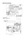
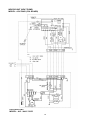
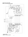
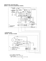
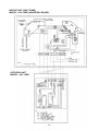
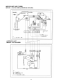
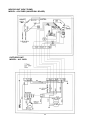
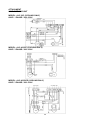
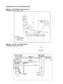
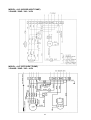
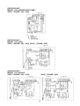
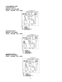
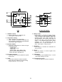
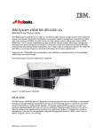
1
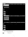
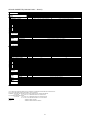
Models:
ACK 20
ACK 25
ACK 30
ACK 40
ACK 50
ACK 15
ACK 20
ACK 25
ACK 30
A/AR
A/AR
A/AR
A/AR
A/AR
B/BR
B/BR
B/BR
B/BR
Ceiling Cassette
Split Systems
Manual No: TMA-ACK-A-1230B
CONTENTS
1. SPECIAL FEATURES ..................................................................................... 2
2. SPECIFICATIONS .......................................................................................... 3
3. NOISE LEVEL ................................................................................................. 9
4. OPERATING RANGE ..................................................................................... 10
5. PERFORMANCE TABLE................................................................................ 11
6. OUTLINES AND DIMENSIONS ..................................................................... 13
7. WIRING DIAGRAMS ..................................................................................... 15
8. SPECIAL PRECAUTIONS FOR R407C ........................................................ 42
9. INSTALLATION OF INDOOR UNIT ............................................................... 44
10. INSTALLATION OF OUTDOOR UNIT ......................................................... 47
11. REFRIGERANT PIPING WORK .................................................................. 48
12. WIRING ....................................................................................................... 49
13. INDICATOR LIGHTS ................................................................................... 50
14. ACCESSORY PARTS ................................................................................. 52
15. OVERALL CHECKING ................................................................................ 53
16. STANDARD OPERATION CONDITIONS .................................................... 53
17. REMOTE CONTROL OPERATION GUIDE.................................................. 54
18. SERVICE AND MAINTENANCE .................................................................. 57
19. PRE START UP MAINTENANCE ................................................................ 58
20. TROUBLESHOOTING ................................................................................. 58
21. PARTS LIST ................................................................................................ 59
1
1. SPECIAL FEATURES
ULTRA SLIM NEW STYLISH DESIGN PROFILE
This unit is contemporary in design and match even the most up to date interior decor. The slim, (only 22 mm
for B-series and only 28 mm for A-series) and round profile front panel of this unit adds a touch of elegance
to every decor.
TURBO MIXED FLOW FAN
Innovative design of highly efficient turbo fan produces an even air circulation in all direction.
BUILT-IN HIGH HEAD DRAIN PUMP
The unit has a built-in high head drain pump (with 500 mm drain head) to provide and ensure smoothness
drainage of condensate water.
STRONG AND ROBUST
The unit is built from strong casing material and robust parts to ensure long lasting reliable service. The drain
pan is made from the POLYSTYRENE with a plastic coating on the surface to ensure no leaking and
condensation occur.
FRIENDLY SERVICEABILITY
The air filter, electrical parts, fan, fan motor and drain pump can all be inspected and replaced from the
bottom of the unit by simply removing the air intake grille. The POLYSTYRENE drain pan and the heat
exchanger coils can be removed from the unit easily by removing the front panel.
MICROCOMPUTER REMOTE CONTROLLER
The incorporated microprocessor offers more accurate control and with the following extra features:
• Fan motor speed can be set at high/medium/low or automatic.
• Timer on/off - the unit can be pre-set to switch on and off automatically.
• Electronic thermostat - room temperature is precisely controlled, resulting in energy saving and increase
comfort.
WIRELESS REMOTE CONTROLLER
The compact wireless remote controller makes it possible to operate the air conditioner anywhere within the
room.
2
2. SPECIFICATIONS
CEILING CASSETTE (COOLING ONLY)
MODEL
INDOOR UNIT
OUTDOOR UNIT
NOMINAL
COOLING
CAPACITY
POWER SOURCE
REFRIGERANT / CONTROL
AIR FLOW
kcal/h
W
Btu/h
V/Ph/Hz
FAN
FAN MOTOR
RATED INPUT POWER (W)
RATED RUNNING CURRENT (A)
COIL
FIN
INDOOR UNIT
TUBE
MATERIAL
DIAMETER
THICKNESS
MATERIAL
THICKNESS
ROW
FIN PER INCH
FACE AREA
DIMENSION
HEIGHT
( ) - WITH PANEL WIDTH
DEPTH
WEIGHT (UNIT + PANEL)
SOUND PRESSURE LEVEL ( H / M / L )
ROOM TEMPERATURE
CONTROL
AIR DISCHARGE
OPERATION
CONDENSATE DRAIN SIZE
AIR FILTER
PACKING
HEIGHT
DIMENSION
WIDTH
( ) - PANEL
DEPTH
RATED RUNNING CURRENT (A)
RATED OUTPUT POWER (W)
RATED INPUT POWER (W)
PIPE
FIN
TUBE
MATERIAL
DIAMETER
THICKNESS
MATERIAL
THICKNESS
ROW
FIN PER INCH
FACE AREA
HEIGHT
DIMENSION
WIDTH
DEPTH
WEIGHT
SOUND PRESSURE LEVEL
MATERIAL
CASING
THICKNESS
FINISHING
TYPE
SIZE
LIQUID
GAS
PACKING
HEIGHT
DIMENSION
WIDTH
DEPTH
COIL
OUTDOOR UNIT
FAN
COMPRESSOR
POWER SOURCE
COMPRESSOR TYPE
CAPACITOR - µ F
1∅
∅ / < 3∅
∅>
LOCK ROTOR AMPERE - A
1∅
∅ / < 3∅
∅>
RATED RUNNING CURRENT - A
1∅
∅ / < 3∅
∅>
RATED INPUT POWER - W
1∅ / < 3∅ >
PROTECTION DEVICE
POWER SOURCE
FAN TYPE / DRIVE
BLADE MATERIAL
DIAMETER
cfm/cmm
50 Hz
60 Hz
50 Hz
60 Hz
50 Hz
60 Hz
mm/in
mm/in
mm/in
2
2
m /ft
mm/in
mm/in
mm/in
kg
dBA
mm/in
mm/in
mm/in
mm/in
V/Ph/Hz
V/Ph/Hz
50 Hz
60 Hz
50 Hz
60 Hz
50 Hz
60 Hz
50 Hz
60 Hz
V/Ph/Hz
mm/in
50 Hz
60 Hz
50 Hz
60 Hz
50 Hz
60 Hz
mm/in
mm/in
mm/in
2
2
m /ft
mm/in
mm/in
mm/in
kg
dBA
mm/in
mm/in
mm/in
mm/in
mm/in
mm/in
ACK 30A
ACK 40A
ACK 50A
ALC 30B
ALC 30C
ALC 40C
ALC 50C
7056
7560
10080
12600
8204
8792
11723
14654
28000
30000
40000
50000
220 - 240 / 1 / 50 , 208 - 230 / 1 / 60
R22 / CAPILLARY TUBE IN OUTDOOR
R22 / CAPILLARY TUBE IN INDOOR
920 / 26.05
770 / 21.81
810 / 22.94
1020 / 28.88
1080 / 30.58
6 POLES x 65W
6 POLES x 35W
6 POLES x 50W
6 POLES x 85W
6 POLES x 120W
6 POLES x 60W
6 POLES x 29W
6 POLES x 45W
6 POLES x 147W 6 POLES x 169W
164
127
151
192
253
198
137
160
308
329
0.69
0.53
0.65
0.80
1.08
0.93
0.62
0.73
1.42
1.50
S.B.C.
S.I.G.C
9.52 / 3/8
7.0 / 0.28
0.35 / 0.014
0.27 / 0.01
ALUMINIUM
ALUMINIUM (HYDROPHILIC TYPE)
0.11 / 0.0043
2
2
2
3
3
16
12
14
20
20
0.469 / 5.022
335 (363) / 13.2 (14.3)
820 (930) / 32.2 (36.6)
820 (930) / 32.2 (36.6)
35 + 4
21 + 4
32 + 4
38 + 4
40 + 4
49 / 45 / 43
42 / 39 / 37
45 / 42 / 40
51 / 48 / 46
53 / 52 / 50
MICROCOMPUTER CONTROLLED THERMOSTAT
4-WAY AUTOMATIC LOUVER ( UP & DOWN )
LCD WIRELESS MICROCOMPUTER REMOTE CONTROL / LED WIRED MICROCOMPUTER REMOTE CONTROL
19.05 / 3/4
CORRUGATED WASHABLE SARAN NET (OPTIONAL IONIZER FILTER)
380 (130) / 15.0 (5.1)
920 (1020) / 36.2 (40.2)
920 (1000) / 36.2 (39.4)
220 - 240 / 1 / 50 / < 380 - 420 / 3 / 50 >
380 - 420 / 3 / 50
208 - 230 / 1 / 60
200 - 230 / 3 / 60
ROTARY (RECIPROCATING) HERMETIC
RECIPROCATING HERMETIC
45 / < NIL >
45 / < NIL >
50
45 / < NIL >
NIL
NIL
40
( 35 )
45
NIL
NIL
56.0 / < 21.4 >
56.5 / < 24.9 >
66.0
85.0 / < 39 >
45.0
62.0
37.0
( 70 )
88.0
78
106
10.00 / < 3.7 >
13.80 / < 4.8 >
14.55
12.66 / < 5.2 >
5.80
8.30
8.75
( 12.26 )
16.30
11.70
14.50
2080 / < 1950 >
2710 / < 2560 >
2980
2577 / < 3050 >
3486
4943
1909
( 2635 )
3420
4040
5270
O/L PROTECTION AND MANUAL RESET HIGH/LOW PRESSURE SW.
OVERLOAD PROTECTION
220 - 240 / 1 / 50 , 208 - 230 / 1 / 60
PROPELLER / DIRECT
GLASS REINFORCE ACRYL STYRENE RESIN
420 / 16.5
609.6 / 24.0
0.56
1.09
0.7
0.76
1.23
55
145
80
55
145
133
241
166
166
261
S.B.C.
S.B.C.
S.I.G.C.
S.I.G.C.
9.52 / 3/8
0.36 / 0.014 AVERAGE
0.35 / 0.014
0.35 / 0.014
ALUMINIUM (SPLIT FIN TYPE)
ALUMINIUM (CORRUGATED FIN TYPE)
0.127 / 0.005
2
2
1
2
2
14
16
16
14
16
0.51 / 5.53
0.87 / 9.33
646 / 25.40
850 / 33.46
840 / 33.10
1030 / 40.53
330 / 13.00
400 / 15.75
57
58
58
95
100
105
52
53
56
60
59
62
GALVANISED MILD STEEL
0.8 / 0.031
POLYESTER POWDER
FLARE VALVE
9.52 / 3/8
9.52 / 3/8
6.35 / 1/4
15.88 / 5/8
19.05 / 3/4
15.88 / 5/8
710 / 27.95
1000 / 39.37
957 / 37.68
1200 / 47.24
461 / 18.15
560 / 22.05
ACK 20A
ALC 20B
5292
6155
21000
ACK 25A
ALC 25B
6300
7327
25000
1) ALL SPECIFICATIONS ARE SUBJECTED TO CHANGE BY THE MANUFACTURER WITHOUT PRIOR NOTICE.
2) ALL UNITS ARE BEING TESTED AND COMPLY TO ARI 210/240-89
3) NOMINAL COOLING AND HEATING CAPACITY ARE BASED ON THE CONDITIONS BELOW :
a) COOLING 26.7°C DB / 19.4°C WB INDOOR AND 35°C DB OUTDOOR
4) ALLOWABLE OPERATING RANGE
a) COOLING 19.4°C DB / 13.9°C WB INDOOR AND 35°C DB OUTDOOR TO
26.7°C DB / 19.4°C WB INDOOR AND 46.1°C DB OUTDOOR
Abbreviation
S.B.C.
S.I.G.C
-
SEAMLESS BARE COPPER
SEAMLESS INNER GROOVE COPPER
3
CEILING CASSETTE (HEAT PUMP)
MODEL
INDOOR UNIT
OUTDOOR UNIT
FAN
NOMINAL
COOLING
CAPACITY
NOMINAL
HEATING
CAPACITY
POWER SOURCE
REFRIGERANT / CONTROL
AIR FLOW
kcal/h
W
Btu/h
kcal/h
W
Btu/h
V/Ph/Hz
FAN MOTOR
COIL
FIN
INDOOR UNIT
TUBE
RATED INPUT POWER (W)
RATED RUNNING CURRENT (A)
MATERIAL
DIAMETER
THICKNESS
MATERIAL
THICKNESS
ROW
FIN PER INCH
FACE AREA
DIMENSION
HEIGHT
( ) - WITH PANEL WIDTH
DEPTH
WEIGHT (UNIT + PANEL)
SOUND PRESSURE LEVEL ( H / M / L )
ROOM TEMPERATURE
CONTROL
AIR DISCHARGE
OPERATION
CONDENSATE DRAIN SIZE
AIR FILTER
PACKING
HEIGHT
DIMENSION
WIDTH
( ) - PANEL
DEPTH
POWER SOURCE
FIN
TUBE
FAN
PIPE
COIL
OUTDOOR UNIT
COMPRESSOR
COMPRESSOR TYPE
CAPACITOR - µ F
1∅
∅ / < 3∅
∅>
LOCK ROTOR AMPERE - A
1 ∅ / < 3∅ >
RATED RUNNING CURR. (COOLING) - A
1∅
∅ / < 3∅
∅>
RATED RUNNING CURR. (HEATING) - A
1 ∅ / < 3∅ >
RATED INPUT POWER (COOLING) - W
1∅
∅ / < 3∅
∅>
RATED INPUT POWER (HEATING) - W
1∅
∅ / < 3∅
∅>
PROTECTION DEVICE
POWER SOURCE
FAN TYPE / DRIVE
BLADE MATERIAL
DIAMETER
RATED RUNNING CURRENT
RATED OUTPUT POWER
RATED INPUT POWER
MATERIAL
DIAMETER
THICKNESS
MATERIAL
THICKNESS
ROW
FIN PER INCH
FACE AREA
HEIGHT
DIMENSION
WIDTH
DEPTH
WEIGHT
SOUND PRESSURE LEVEL
MATERIAL
CASING
THICKNESS
FINISHING
TYPE
SIZE
LIQUID
GAS
PACKING
HEIGHT
DIMENSION
WIDTH
DEPTH
cfm/cmm
50Hz
60Hz
W (50/60Hz)
A (50/60Hz)
mm/in
mm/in
mm/in
2
2
m /ft
mm/in
mm/in
mm/in
kg
dBA
mm/in
mm/in
mm/in
mm/in
V/Ph/Hz
V/Ph/Hz
50
60
50
60
50
60
50
60
50
60
50
60
Hz
Hz
Hz
Hz
Hz
Hz
Hz
Hz
Hz
Hz
Hz
Hz
V/Ph/Hz
mm/in
A (50/60Hz)
W (50/60Hz)
W (50/60Hz)
mm/in
mm/in
mm/in
2
2
m /ft
mm/in
mm/in
mm/in
kg
dBA
mm/in
mm/in
mm/in
mm/in
mm/in
mm/in
ACK 20AR
ALC 20BR
5040
5862
20000
5040
5862
20000
ACK 25AR
ALC 25BR
6300
7327
25000
6300
7327
25000
ACK 30AR
ACK 40AR
ACK 50AR
ALC 30CR
ALC 40CR
ALC 50CR
7560
10080
12096
8792
11723
14068
30000
40000
48000
7812
10332
12600
9086
12016
14654
31000
41000
50000
220 - 240 / 1 / 50 , 208 - 230 / 1 / 60
R22 / CAPILLARY TUBE IN OUTDOOR
R22 / CAPILLARY TUBE & TXV IN OUTDOOR
770 / 21.81
810 / 22.94
920 / 26.05
1020 / 28.88
1080 / 30.58
6 POLES x 35W
6 POLES x 50W
6 POLES x 65W
6 POLES x 85W
6 POLES x 120W
6 POLES x 29W
6 POLES x 45W
6 POLES x 60W
6 POLES x 147W
6 POLES x 169W
127 / 137
151 / 160
164 / 198
192 / 308
253 / 329
0.53 / 0.62
0.65 / 0.73
0.69 / 0.93
0.80 / 1.42
1.08 / 1.50
S.B.C.
S.I.G.C
9.52 / 3/8
7.0 / 0.28
0.35 / 0.014
0.27 / 0.01
ALUMINIUM
ALUMINIUM (HYDROPHILIC TYPE)
0.11 / 0.0043
2
2
2
3
3
12
16
16
20
20
0.469 / 5.022
335 (363) / 13.2 (14.3)
820 (930) / 32.2 (36.6)
820 (930) / 32.2 (36.6)
21 + 4
32 + 4
35 + 4
38 + 4
40 + 4
42 / 39 / 37
45 / 42 / 40
49 / 45 / 43
51 / 48 / 46
53 / 52 / 50
MICROCOMPUTER CONTROLLED THERMOSTAT
4 - WAY AUTOMATIC LOUVER ( UP & DOWN )
LCD WIRELESS / LED WIRED MICROCOMPUTER REMOTE CONTROL
19.05 / 3/4
WASHABLE SARAN NET (OPTIONAL IONIZER FILTER)
380 (130) / 15.0 (5.1)
920 (1020) / 36.2 (40.2)
920 (1000) / 36.2 (39.4)
220 - 240 / 1 / 50 / < 380 - 420 / 3 / 50 >
380 - 420 / 3 / 50
208 - 230 / 1 / 60
200 - 230 / 3 / 60
ROTARY HERMETIC
RECIPROCATING HERMETIC
45 / < NIL >
45 / < NIL >
45 / < NIL >
NIL
NIL
40
60
45
NIL
NIL
56 / < 21.4 >
57 / < 24.9 >
85 / < 39 >
45
62
39.6
50
88
78
106
9.84 / < 3.7 >
13.0 / < 4.8 >
13.4 / < 5.0 >
6.0
7.8
8.30
11.6
15.3
11.2
14.8
9.84 / < 3.7 >
12.7 / < 4.9 >
12.9 / < 4.9 >
5.4
7.2
8.70
11.4
14.2
10.0
12.4
1987 / < 1950 >
2730 / < 2560 >
2643 / < 2900 >
3431
4634
1777
2486
3144
3595
4905
2008 / < 1960 >
2650 / < 2640 >
2562 / < 2756 >
2921
4036
1824
2420
2846
3042
3739
OVERLOAD
PROTECTION
&
MANUAL
RESET
HIGH
PRESSURE
SWITCH
OVERLOAD PROTECTION
220 - 240 / 1 / 50 , 208 - 230 / 1 / 60
PROPELLER / DIRECT
GLASS REINFORCED ACRYL STYRENE RESIN
420.0 / 16.5
609.6 / 24.0
0.56 / 0.76
1.09 / 1.25
55 / 55
145 / 145
133 / 165
241 / 261
S.B.C
S.I.G.C
S.B.C
S.I.G.C
S.I.G.C
9.52 / 3/8
0.36 / 0.014 AVERAGE
0.35 / 0.014
0.36 / 0.014 AVERAGE
0.35 / 0.014
ALUMINIUM (SLIT FIN TYPE)
ALUMINIUM (CORRUGATED FIN TYPE)
0.127 / 0.005
2
2
14
16
0.51 / 5.53
0.87 / 9.33
646 / 25.40
850 / 33.46
840 / 33.10
1029 / 40.53
330 / 13.00
400 / 15.75
57
58
95
100
105
52
53
60
59
62
GALVANISED MILD STEEL
0.8 / 0.031
POLYESTER POWDER
FLARE VALVE
9.52 / 3/8
9.52 / 3/8
6.35 / 1/4
15.88 / 5/8
19.05 / 3/4
15.88 / 5/8
710 / 27.95
1000 / 39.37
957 / 37.68
1200 / 47.24
461 / 18.15
560 / 22.05
1) ALL SPECIFICATIONS ARE SUBJECTED TO CHANGE BY THE MANUFACTURER WITHOUT PRIOR NOTICE.
2) ALL UNITS ARE BEING TESTED AND COMPLY TO ARI 210/240-89
3) NOMINAL COOLING AND HEATING CAPACITY ARE BASED ON THE CONDITIONS BELOW :
a) COOLING 26.7°C DB / 19.4°C WB INDOOR AND 35°C DB OUTDOOR
b) HEATING 21.1°C DB / 15.6°C WB INDOOR AND 8.3°C DB / 6.1°C WB OUTDOOR
4) ALLOWABLE OPERATING RANGE
a) COOLING –
19.4°C DB / 13.9°C WB INDOOR AND 35°C DB OUTDOOR TO
26.7°C DB / 19.4°C WB INDOOR AND 46.1°C DB OUTDOOR
b) HEATING –
21.0°C DB INDOOR AND –8.3°C DB / -9.4°C WB OUTDOOR TO
26.7°C DB INDOOR AND 23.9°C DB / 18.3°C WB OUTDOOR
Abbreviation
S.B.C.
S.I.G.C
-
SEAMLESS BARE COPPER
SEAMLESS INNER GROOVE COPPER
4
CEILING CASSETTE (COOLING ONLY – R407C)
INDOOR UNIT
OUTDOOR UNIT
NOMINAL
kcal/h
COOLING
W
CAPACITY
Btu/h
POWER SOURCE
V/Ph/Hz
REFRIGERANT / CONTROL
AIR FLOW
cfm/cmm
FAN MOTOR
RATED INPUT POWER
W
RATED RUNNING CURRENT
A
MATERIAL
DIAMETER
mm/in
THICKNESS
mm/in
MATERIAL
THICKNESS
mm/in
ROW
FIN PER INCH
2 2
FACE AREA
m /ft
DIMENSION
HEIGHT
mm/in
( ) - WITH PANEL WIDTH
mm/in
DEPTH
mm/in
WEIGHT (UNIT + PANEL)
kg
SOUND PRESSURE LEVEL ( H / M / L )
dBA
ROOM TEMPERATURE
CONTROL
AIR DISCHARGE
OPERATION
CONDENSATE DRAIN SIZE
mm/in
AIR FILTER
PACKING
HEIGHT
mm/in
DIMENSION
WIDTH
mm/in
( ) - PANEL
DEPTH
mm/in
POWER SOURCE
V/Ph/Hz
COMPRESSOR TYPE
CAPACITOR
µF
LOCK ROTOR AMPERE
A
RATED RUNNING CURRENT
A
RATED INPUT POWER
W
PROTECTION DEVICE
POWER SOURCE
V/Ph/Hz
FAN TYPE / DRIVE
BLADE MATERIAL
DIAMETER
mm/in
RATED RUNNING CURRENT
A
RATED OUTPUT POWER
W
RATED INPUT POWER
W
MATERIAL
DIAMETER
mm/in
THICKNESS
mm/in
MATERIAL
THICKNESS
mm/in
ROW
FIN PER INCH
2 2
FACE AREA
m /ft
HEIGHT
mm/in
DIMENSION
WIDTH
mm/in
DEPTH
mm/in
WEIGHT
kg
SOUND PRESSURE LEVEL
dBA
MATERIAL
CASING
THICKNESS
mm/in
FINISHING
TYPE
SIZE
LIQUID
mm/in
GAS
mm/in
PACKING
HEIGHT
mm/in
DIMENSION
WIDTH
mm/in
DEPTH
mm/in
REFRIGERANT CHARGE
kg
COIL
INDOOR UNIT
TUBE
FIN
COIL
PIPE
OUTDOOR UNIT
FAN
COMPRESSOR
FIN
TUBE
FAN
MODEL
ACK 20A
A4LC 20B
4612
5363
18300
ACK 25A
A4LC 25B
5292
6155
21000
ACK 30A
ACK 40A
ACK 50A
A4LC 30C
A4LC 40C
A4LC 50C
7560
9576
12600
8792
11134
14650
30000
38000
50000
220 - 240 / 1 / 50
R407C / CAPILLARY TUBE (OUTDOOR)
R407C / CAPILLARY TUBE (INDOOR)
770 / 21.81
810 / 22.94
920 / 26.05
1020 / 28.88
1080 / 30.58
6 POLES x 35W
6 POLES x 50W
6 POLES x 65W
6 POLES x 85W
6 POLES x 120W
127
151
164
192
253
0.53
0.65
0.69
0.80
1.08
S.B.C.
S.I.G.C
9.52 / 3/8
7.0 / 0.28
0.35 / 0.014
0.27 / 0.01
ALUMINIUM
ALUMINIUM (HYDROPHILIC TYPE)
0.11 / 0.0043
2
2
2
3
3
12
14
16
20
20
0.469 / 5.022
0.469 / 5.022
0.469 / 5.022
0.469 / 5.022
0.469 / 5.022
335 (363) / 13.2 (14.3)
820 (930) / 32.2 (36.6)
820 (930) / 32.2 (36.6)
21 + 4
32 + 4
35 + 4
38 + 4
40 + 4
42 / 39 / 37
45 / 42 / 40
49 / 45 / 43
51 / 48 / 46
53 / 52 / 50
MICROCOMPUTER CONTROLLED THERMOSTAT
4-WAY AUTOMATIC LOUVER ( UP & DOWN )
LCD WIRELESS MICROCOMPUTER REMOTE CONTROL / LED WIRED MICROCOMPUTER REMOTE CONTROL
19.05 / 3/4
CORRUGATED WASHABLE SARAN NET (OPTIONAL IONIZER FILTER)
380 (130) / 15.0 (5.1)
920 (1020) / 36.2 (40.2)
920 (1000) / 36.2 (39.4)
220 - 240 / 1 / 50
380 - 420 / 3 / 50
ROTARY HERMETIC
SCROLL
45
50
50
NIL
NIL
54
58
78
45
62
9.91
12.50
11.40
6.30
8.20
2112
2660
2560
3741
4328
OVERLOAD PROTECTION
O/L PROTECTION AND MANUAL RESET HIGH/LOW PRESSURE SW.
220 - 240 / 1 / 50
PROPELLER / DIRECT
GLASS REINFORCE ACRYL STYRENE RESIN
420 / 16.5
609.6 / 24.0
0.56
1.09
55
145
133
241
SEAMLESS COPPER
9.52 / 3/8
0.36 / 0.014
ALUMINIUM (SPLIT FIN TYPE)
0.127 / 0.005
2
1
2
2
14
16
16
16
0.51 / 5.53
0.87 / 9.33
646 / 25.40
850 / 33.46
840 / 33.10
1030 / 40.53
330 / 13.00
400 / 15.75
57
58
95
100
105
52
53
60
59
62
GALVANISED MILD STEEL
0.8 / 0.031
EPOXY POLYESTER POWDER
FLARE VALVE / AEROQUIP
FLARE VALVE
9.52 / 3/8
9.52 / 3/8
6.35 / 1/4
15.88 / 5/8
19.05 / 3/4
15.88 / 5/8
710 / 27.95
1000 / 39.37
957 / 37.68
1200 / 47.24
461 / 18.15
560 / 22.05
1.65
1.65
1.90
3.13
3.15
1) ALL SPECIFICATIONS ARE SUBJECTED TO CHANGE BY THE MANUFACTURER WITHOUT PRIOR NOTICE.
2) ALL UNITS ARE BEING TESTED AND COMPLY TO ARI 210/240-89
3) NOMINAL COOLING AND HEATING CAPACITY ARE BASED ON THE CONDITIONS BELOW :
a) COOLING 26.7°C DB / 19.4°C WB INDOOR AND 35°C DB OUTDOOR
4) ALLOWABLE OPERATING RANGE
a) COOLING 19.4°C DB / 13.9°C WB INDOOR AND 35°C DB OUTDOOR TO
26.7°C DB / 19.4°C WB INDOOR AND 46.1°C DB OUTDOOR
Abbreviation
S.B.C.
SEAMLESS BARE COPPER
S.I.G.C
SEAMLESS INNER GROOVE COPPER
5
CEILING CASSETTE (HEAT PUMP – R407C)
MODEL
INDOOR UNIT
OUTDOOR UNIT
COIL
INDOOR UNIT
TUBE
FIN
COIL
PIPE
OUTDOOR UNIT
FAN
COMPRESSOR
FIN
TUBE
FAN
NOMINAL
COOLING
CAPACITY
NOMINAL
HEATING
CAPACITY
POWER SOURCE
REFRIGERANT / CONTROL
AIR FLOW
FAN MOTOR
RATED INPUT POWER
RATED RUNNING CURRENT
MATERIAL
DIAMETER
THICKNESS
MATERIAL
THICKNESS
ROW
FIN PER INCH
FACE AREA
DIMENSION
HEIGHT
( ) - WITH PANEL WIDTH
DEPTH
WEIGHT (UNIT + PANEL)
SOUND PRESSURE LEVEL ( H / M / L )
ROOM TEMPERATURE
CONTROL
AIR DISCHARGE
OPERATION
CONDENSATE DRAIN SIZE
AIR FILTER
PACKING
HEIGHT
DIMENSION
WIDTH
( ) - PANEL
DEPTH
POWER SOURCE
COMPRESSOR TYPE
CAPACITOR
LOCK ROTOR AMPERE
RATED RUNNING CURRENT (COOLING)
RATED RUNNING CURRENT (HEATING)
RATED INPUT POWER (COOLING)
RATED INPUT POWER (HEATING)
PROTECTION DEVICE
POWER SOURCE
FAN TYPE / DRIVE
BLADE MATERIAL
DIAMETER
RATED RUNNING CURRENT
RATED OUTPUT POWER
RATED INPUT POWER
MATERIAL
DIAMETER
THICKNESS
MATERIAL
THICKNESS
ROW
FIN PER INCH
FACE AREA
HEIGHT
DIMENSION
WIDTH
DEPTH
WEIGHT
SOUND PRESSURE LEVEL
MATERIAL
CASING
THICKNESS
FINISHING
TYPE
SIZE
LIQUID
GAS
PACKING
HEIGHT
DIMENSION
WIDTH
DEPTH
REFRIGERANT CHARGE
kcal/h
W
Btu/h
kcal/h
W
Btu/h
V/Ph/Hz
cfm/cmm
W
A
mm/in
mm/in
mm/in
2
2
m /ft
mm/in
mm/in
mm/in
kg
dBA
mm/in
mm/in
mm/in
mm/in
V/Ph/Hz
µF
A
A
A
W
W
V/Ph/Hz
mm/in
A
W
W
mm/in
mm/in
mm/in
2
2
m /ft
mm/in
mm/in
mm/in
kg
dBA
mm/in
mm/in
mm/in
mm/in
mm/in
mm/in
kg
ACK 20AR
A4LC 20BR
4536
5274
18000
4790
5569
19000
ACK 25AR
A4LC 25BR
5170
6008
20500
6050
7034
24000
R407C / CAPILLARY TUBE (OUTDOOR)
770 / 21.81
810 / 22.94
6 POLES x 35W
6 POLES x 50W
127
151
0.53
0.65
S.B.C.
9.52 / 3/8
0.35 / 0.014
ALUMINIUM
ACK 30AR
A4LC 30CR
7310
8499
29000
7812
9083
31000
220 - 240 / 1 / 50
R407C / TXV (OUTDOOR)
-
ACK 50AR
A4LC 50CR
12100
14068
48000
12600
14654
50000
R407C / CAPILLARY TUBE + TXV (OUTDOOR)
1020 / 28.88
6 POLES x 85W
192
0.8
1080 / 30.58
6 POLES x 120W
253
1.08
S.I.G.C
7.0 / 0.28
0.27 / 0.01
ALUMINIUM (HYDROPHILIC TYPE)
0.11 / 0.0043
2
3
3
16
20
20
0.469 / 5.022
0.469 / 5.022
0.469 / 5.022
335 (363) / 13.2 (14.3)
820 (930) / 32.2 (36.6)
820 (930) / 32.2 (36.6)
21 + 4
32 + 4
35 + 4
38 + 4
40 + 4
42 / 39 / 37
45 / 42 / 40
49 / 45 / 43
51 / 48 / 46
53 / 52 / 50
MICROCOMPUTER CONTROLLED THERMOSTAT
4 - WAY AUTOMATIC LOUVER ( UP & DOWN )
LCD WIRELESS / LED WIRED MICROCOMPUTER REMOTE CONTROL
19.05 / 3/4
WASHABLE SARAN NET (OPTIONAL IONIZER FILTER)
380 (130) / 15.0 (5.1)
920 (1020) / 36.2 (40.2)
920 (1000) / 36.2 (39.4)
220 - 240 / 1 / 50
380 - 420 / 3 / 50
ROTARY HERMETIC
SCROLL
45
50
50
NIL
NIL
54
58
78
45
62
9.50
12.60
11.50
6.20
8.80
10.10
12.50
11.40
5.90
7.80
2002
2571
2424
3565
4615
2096
2549
2407
3280
3734
OVERLOAD PROTECTION
O/L PROTECTION AND MANUAL RESET HIGH PRESSURE SW.
220 - 240 / 1 / 50
PROPELLER / DIRECT
GLASS REINFORCED ACRYL STYRENE RESIN
420.0 / 16.5
609.6 / 24.0
0.56
1.09
55
145
133
241
SEAMLESS COPPER
9.52 / 3/8
0.36/ 0.014
ALUMINIUM (SLIT FIN TYPE)
0.127 / 0.005
2
2
14
16
0.51 / 5.53
0.87 / 9.33
646 / 25.40
850 / 33.46
840 / 33.10
1029 / 40.53
330 / 13.00
400 / 15.75
57
58
95
100
105
52
53
60
59
62
GALVANISED MILD STEEL
0.8 / 0.031
EPOXY POLYESTER POWDER
FLARE VALVE / AEROQUIP
FLARE VALVE
9.52 / 3/8
9.52 / 3/8
6.35 / 1/4
15.88 / 5/8
19.05 / 3/4
15.88 / 5/8
710 / 27.95
1000 / 39.37
957 / 37.68
1200 / 47.24
461 / 18.15
560 / 22.05
1.70
1.65
2.35
3.10
3.35
2
12
0.469 / 5.022
2
16
0.469 / 5.022
1) ALL SPECIFICATIONS ARE SUBJECTED TO CHANGE BY THE MANUFACTURER WITHOUT PRIOR NOTICE.
2) ALL UNITS ARE BEING TESTED AND COMPLY TO ARI 210/240-89
3) NOMINAL COOLING AND HEATING CAPACITY ARE BASED ON THE CONDITIONS BELOW :
a) COOLING 26.7°C DB / 19.4°C WB INDOOR AND 35°C DB OUTDOOR
b) HEATING 21.1°C DB / 15.6°C WB INDOOR AND 8.3°C DB / 6.1°C WB OUTDOOR
4) ALLOWABLE OPERATING RANGE
a) COOLING –
19.4°C DB / 13.9°C WB INDOOR AND 35°C DB OUTDOOR TO
26.7°C DB / 19.4°C WB INDOOR AND 46.1°C DB OUTDOOR
b) HEATING –
21.0°C DB INDOOR AND –8.3°C DB / -9.4°C WB OUTDOOR TO
26.7°C DB INDOOR AND 23.9°C DB / 18.3°C WB OUTDOOR
Abbreviation
S.B.C.
S.I.G.C
920 / 26.05
6 POLES x 65W
164
0.69
ACK 40AR
A4LC 40CR
9830
11430
39000
10332
12013
41000
SEAMLESS BARE COPPER
SEAMLESS INNER GROOVE COPPER
6
CEILING CASSETTE (COOLING ONLY)
MODEL
INDOOR UNIT
OUTDOOR UNIT
COIL
INDOOR UNIT
TUBE
FIN
COIL
PIPE
OUTDOOR UNIT
FAN
COMPRESSOR
FIN
TUBE
FAN
NOMINAL
kcal/h
COOLING
W
CAPACITY
Btu/h
POWER SOURCE
V/Ph/Hz
REFRIGERANT / CONTROL
AIR FLOW
cfm/cmm
FAN MOTOR
RATED INPUT POWER
W
RATED RUNNING CURRENT
A
MATERIAL
DIAMETER
mm/in
THICKNESS
mm/in
MATERIAL
THICKNESS
mm/in
ROW
FIN PER INCH
2 2
m /ft
FACE AREA
DIMENSION
HEIGHT
mm/in
WIDTH
mm/in
( ) - WITH PANEL
DEPTH
mm/in
WEIGHT ( UNIT + PANEL)
kg
SOUND PRESSURE LEVEL ( H / M / L )
dBA
ROOM TEMPERATURE
CONTROL
AIR DISCHARGE
OPERATION
CONDENSATE DRAIN SIZE
mm/in
AIR FILTER
PACKING
HEIGHT
mm/in
DIMENSION
WIDTH
mm/in
( ) - PANEL
DEPTH
mm/in
POWER SOURCE
V/Ph/Hz
COMPRESSOR TYPE
CAPACITOR
µF
LOCK ROTOR AMP.
A
RATED RUNNING CURRENT
A
RATED INPUT POWER
W
PROTECTION DEVICE
POWER SOURCE
V/Ph/Hz
FAN TYPE / DRIVE
BLADE MATERIAL
DIAMETER
mm/in
RATED RUNNING CURRENT
A
RATED OUTPUT POWER
W
RATED INPUT POWER
W
MATERIAL
DIAMETER
mm/in
THICKNESS
mm/in
MATERIAL
THICKNESS
mm/in
ROW
FIN PER INCH
2 2
FACE AREA
m /ft
HEIGHT
mm/in
DIMENSION
WIDTH
mm/in
DEPTH
mm/in
WEIGHT
kg
SOUND PRESSURE LEVEL
dBA
MATERIAL
CASING
THICKNESS
mm/in
FINISHING
TYPE
SIZE
LIQUID
mm/in
GAS
mm/in
PACKING
HEIGHT
mm/in
DIMENSION
WIDTH
mm/in
DEPTH
mm/in
ACK 15B
ALC 15B
3150
3664
12500
ACK 20B
ALC 20B
4788
5569
19000
R22 / CAPILLARY TUBE IN OUTDOOR
440 / 12.5
6 POLES
68
0.3
-
ACK 30B
ALC 30B
7182
8353
28500
ALC 30C
7560
8792
30000
R22 / CAPILLARY TUBE IN INDOOR
500 / 14.5
560 / 15.9
6 POLES
6 POLES
79
93
0.3
0.4
S.I.G.C
9.52 / 3/8
0.35 / 0.014
ALUMINIUM (SLIT FIN )
0.11 / 0.0043
2
14
0.38 / 4.1
293 (345) / 11.5 (13.6)
650 (727) / 25.6 (28.6)
650 (727) / 25.6 (28.6)
30 + 3
30 + 3
31 + 3
32 + 3
42 / 38 / 35
42 / 38 / 35
45 / 42 / 40
48 / 45 / 43
MICROCOMPUTER CONTROLLED THERMOSTAT
4 WAY MANUAL LOUVER
WIRELESS OR WIRED MICROCOMPUTER REMOTE CONTROL
19.05 / 3/4
CORRUGATED WASHABLE SARAN NET (OPTIONAL IONIZER FILTER)
360 (110) / 14.2 (4.3)
725 (840) / 28.5 (33.1)
725 (840) / 28.5 (33.1)
220 - 240 / 1 / 50
ROTARY HERMETIC
RECIP. HER.
45
45
50
45
30
25
56
57
66
85
5.7
10.1
12.3
14.6
13.1
1323
2112
2660
2983
2674
440 / 12.5
6 POLES
68
0.3
OVERLOAD PROTECTION
O/L & H-L PRESSURE SW
220 - 240 / 1 / 50
PROPELLER / DIRECT
GLASS REINFORCED ACRYL STYRENE RESIN
355 / 14
420 / 16.5
0.28
0.7
0.56
30
80
55
62
166
133
S.I.G.C
S.B.C
S.I.G.C
S.I.G.C
9.52 / 3/8
0.35 / 0.014
0.36 / 0.014 AVERAGE
0.35 / 0.014
ALUMINIUM (SLIT FIN )
ALUMINIUM (CORR.)
1
19
0.32 / 3.5
494 / 19.4
740 / 29.1
270 / 10.6
34
49
6.35 / 1/4
12.70 / 1/2
558 / 22.0
851 / 33.5
401 / 15.8
1) ALL SPECIFICATIONS ARE SUBJECTED TO CHANGE BY THE MANUFACTURER WITHOUT PRIOR NOTICE.
2) ALL UNITS ARE BEING TESTED AND COMPLY TO ARI 210/240-89
3) NOMINAL COOLING AND HEATING CAPACITY ARE BASED ON THE CONDITIONS BELOW :
a) COOLING 26.7°C DB / 19.4°C WB INDOOR AND 35°C DB OUTDOOR
4) ALLOWABLE OPERATING RANGE
a) COOLING 19.4°C DB / 13.9°C WB INDOOR AND 35°C DB OUTDOOR TO
26.7°C DB / 19.4°C WB INDOOR AND 46.1°C DB OUTDOOR
Abbreviation
S.B.C.
S.I.G.C
ACK 25B
ALC 25B
6048
7034
24000
220 - 240 / 1 / 50
SEAMLESS BARE COPPER
SEAMLESS INNER GROOVE COPPER
7
2
14
57
52
0.127 / 0.005
2
14
0.51 / 5.53
646 / 25.4
840 / 33.1
330 / 13.0
58
53
GALVANISED MILD STEEL
0.8 / 0.031
POLYESTER POWDER
FLARE VALVE
6.35 / 1/4
15.88 / 5/8
2
16
58
56
610 / 24
1.09
145
241
S.B.C.
1
16
0.87 / 9.33
850 / 33.5
1030 / 40.6
400 / 15.8
95
60
9.52 / 3/8
15.88 / 5/8
710 / 28.0
957 / 37.7
461 / 18.1
1000 / 39.4
1200 / 47.2
560 / 22.1
CEILING CASSETTE (HEAT PUMP)
MODEL
INDOOR UNIT
OUTDOOR UNIT
COIL
INDOOR UNIT
TUBE
FIN
COIL
PIPE
OUTDOOR UNIT
FAN
COMPRESSOR
FIN
TUBE
FAN
NOMINAL
kcal/h
COOLING
W
CAPACITY
Btu/h
NOMINAL
kcal/h
HEATING
W
CAPACITY
Btu/h
POWER SOURCE
V/Ph/Hz
REFRIGERANT / CONTROL
AIR FLOW
cfm/cmm
FAN MOTOR
RATED INPUT POWER
W
RATED RUNNING CURRENT
A
MATERIAL
DIAMETER
mm/in
THICKNESS
mm/in
MATERIAL
THICKNESS
mm/in
ROW
FIN PER INCH
2 2
m /ft
FACE AREA
DIMENSION
HEIGHT
mm/in
mm/in
( ) - WITH PANEL WIDTH
DEPTH
mm/in
WEIGHT ( UNIT + PANEL)
kg
SOUND PRESSURE LEVEL ( H / M / L )
dBA
ROOM TEMPERATURE
CONTROL
AIR DISCHARGE
OPERATION
CONDENSATE DRAIN SIZE
mm/in
AIR FILTER
PACKING
HEIGHT
mm/in
DIMENSION
WIDTH
mm/in
( ) - PANEL
DEPTH
mm/in
POWER SOURCE
V/Ph/Hz
COMPRESSOR TYPE
CAPACITOR
µF
LOCK ROTOR AMP.
A
RATED RUNNING CURRENT (COOLING)
A
RATED RUNNING CURRENT (HEATING)
A
RATED INPUT POWER (COOLING)
W
RATED INPUT POWER (HEATING)
W
PROTECTION DEVICE
POWER SOURCE
V/Ph/Hz
FAN TYPE / DRIVE
BLADE MATERIAL
DIAMETER
mm/in
RATED RUNNING CURRENT
A
RATED OUTPUT POWER
W
RATED INPUT POWER
W
MATERIAL
DIAMETER
mm/in
THICKNESS
mm/in
MATERIAL
THICKNESS
mm/in
ROW
FIN PER INCH
2 2
FACE AREA
m /ft
HEIGHT
mm/in
DIMENSION
WIDTH
mm/in
DEPTH
mm/in
WEIGHT
kg
SOUND PRESSURE LEVEL
dBA
MATERIAL
CASING
THICKNESS
mm/in
FINISHING
TYPE
SIZE
LIQUID
mm/in
GAS
mm/in
PACKING
HEIGHT
mm/in
DIMENSION
WIDTH
mm/in
DEPTH
mm/in
ACK 15BR
ALC 15BR
0
0
0
0
0
0
ACK 20BR
ALC 20BR
4536
5275
18000
4914
5715
19500
-
ACK 30BR
ALC 30CR
7056
8206
28000
7308
8499
29000
220 - 240 / 1 / 50
R22 / CAPILLARY TUBE IN OUTDOOR
440 / 12.5
440 / 12.5
500 / 14.5
560 / 15.9
6 POLES
6 POLES
6 POLES
6 POLES
68
68
79
93
0.3
0.3
0.3
0.4
S.I.G.C
9.52 / 3/8
0.35 / 0.014
ALUMINIUM (SLIT FIN )
0.11 / 0.0043
2
14
0.38/4.1
293 (345) / 11.5 (13.6)
650 (727) / 25.6 (28.6)
650 (727) / 25.6 (28.6)
30 + 3
30 + 3
31 + 3
32 + 3
42 / 38 / 35
42 / 38 / 35
45 / 42 / 40
48 / 45 / 43
MICROCOMPUTER CONTROLLED THERMOSTAT
4 WAY MANUAL LOUVER
WIRELESS OR WIRED MICROCOMPUTER REMOTE CONTROL
19.05 / 3/4
CORRUGATED WASHABLE SARAN NET (OPTIONAL IONIZER FILTER)
360 (110) / 14.2 (4.3)
725 (840) / 28.5 (33.1)
725 (840) / 28.5 (33.1)
220 - 240 / 1 / 50
RECIPROCATING HER.
ROTARY HERMETIC
30
45
45
45
25
56
57
85
10.1
12.3
11.8
9.3
11.6
12.9
2112
2660
2385
1886
2461
2469
O/L & HI PRESSURE SW.
OVERLOAD PROTECTION
220 - 240 / 1 / 50
PROPELLER / DIRECT
GLASS REINFORCED ACRYL STYRENE RESIN
355 / 14
610 / 24
420 / 16.5
0.28
1.09
0.56
30
145
55
62
241
133
S.I.G.C
S.B.C
S.I.G.C
S.B.C
9.52 / 3/8
0.36 / 0.014 AVERAGE
0.35 / 0.014
0.35 / 0.014
ALUMINIUM (CORR.)
ALUMINIUM (SLIT FIN )
0.127 / 0.005
1
2
2
1
19
14
14
16
0.32 / 3.5
0.87 / 9.33
0.51 / 5.53
494 / 19.4
850 / 33.5
646 / 25.4
740 / 29.1
1030 / 40.6
840 / 33.1
270 / 10.6
400 / 15.8
330 / 13.0
34
57
58
95
49
52
53
60
GALVANISED MILD STEEL
0.8 / 0.031
POLYESTER POWDER
FLARE VALVE
6.35 / 1/4
6.35 / 1/4
9.52 / 3/8
12.70 / 1/2
15.88 / 5/8
15.88 / 5/8
558 / 22.0
1000 / 39.4
710 / 28.0
851 / 33.5
1200 / 47.2
957 / 37.7
401 / 15.8
560 / 22.1
461 / 18.1
1) ALL SPECIFICATIONS ARE SUBJECTED TO CHANGE BY THE MANUFACTURER WITHOUT PRIOR NOTICE.
2) ALL UNITS ARE BEING TESTED AND COMPLY TO ARI 210/240-89
3) NOMINAL COOLING AND HEATING CAPACITY ARE BASED ON THE CONDITIONS BELOW :
a) COOLING 26.7°C DB / 19.4°C WB INDOOR AND 35°C DB OUTDOOR
b) HEATING 21.1°C DB / 15.6°C WB INDOOR AND 8.3°C DB / 6.1°C WB OUTDOOR
4) ALLOWABLE OPERATING RANGE
a) COOLING –
19.4°C DB / 13.9°C WB INDOOR AND 35°C DB OUTDOOR TO
26.7°C DB / 19.4°C WB INDOOR AND 46.1°C DB OUTDOOR
b) HEATING –
21.0°C DB INDOOR AND –8.3°C DB / -9.4°C WB OUTDOOR TO
26.7°C DB INDOOR AND 23.9°C DB / 18.3°C WB OUTDOOR
Abbreviation
S.B.C.
S.I.G.C
ACK 25BR
ALC 25BR
5796
6741
23000
5796
6741
23000
SEAMLESS BARE COPPER
SEAMLESS INNER GROOVE COPPER
8
3. NOISE LEVEL
Model
125Hz
H M L
1/1 Octave A-weighed sound pressure level (dBA), ref 20µPa
250Hz
500Hz
1kHz
2kHz
4kHz
8kHz
H M L H M L H M L H M L H M L H M L
ACK20A/AR
ACK25A/AR
ACK30A/AR
ACK40A/AR
ACK50A/AR
46
44
43
45
43
42
40
37
35
38
33
31
32
28
26
21
18
17
14
12
11 42
39
37
48
45
43
46
43
42
43
40
38
39
35
32
33
29
27
27
21
19
19
15
14
45
42
40
50
48
46
48
45
43
47
43
41
43
38
35
37
32
30
35
31
30
28
27
26
49
45
43
50
48
46
49
47
45
49
47
46
46
43
41
39
36
34
38
34
30
31
25
23
51
48
46
54
52
51
52
50
49
51
50
49
48
46
45
43
41
39
42
40
39
34
32
31
53
52
50
Model
Measuring location
ACK20A/AR
ACK25A/AR
Standard : JIS C 9612
ACK30A/AR
ACK40A/AR
ACK50A/AR
Standard : JIS B 8615
9
Ave.
H M L
4. OPERATING RANGE
Ensure the operating temperature is in allowable range.
Cooling only
Cooling
Caution :
Outdoor temp. (°CDB)
54
HIGH AMBIENT
UNIT
46
The use of your air conditioner
outside the range of working
temperature and humidity can
result in serious failure.
35
STD
19
LOW AMBIENT
KIT
-5
24
15
Indoor temp. (°CWB)
Heat pump
Heating
Cooling
54
Outdoor temp. (°CDB)
Outdoor temp. (°CWB)
18
6
STD
-8
HIGH AMBIENT
UNIT
46
35
STD
19
LOW AMBIENT
KIT
-5
15
21
27
15
Indoor temp. (°CDB)
24
Indoor temp. (°CWB)
10
5. PERFORMANCE TABLE
MODEL : ACK20A / ALC20B
Indoor DB
°C
26.7
Indoor WB
°C
13.9
15
18
19.4
20
22
24
Capacity
kW
TC
SC
TC
SC
TC
SC
TC
SC
TC
SC
TC
SC
TC
SC
19.4
25
5.353
5.353
5.644
5.333
6.439
5.278
6.809
5.252
6.968
5.241
7.498
5.205
8.028
5.168
5.146
5.146
5.431
5.114
6.211
5.026
6.574
4.986
6.709
4.951
7.156
4.837
7.604
4.722
Outdoor DB, ° C
30
35
4.961
4.961
5.242
4.918
6.007
4.802
6.365
4.747
6.477
4.692
6.851
4.508
7.225
4.324
4.776
4.776
5.052
4.723
5.804
4.577
6.155
4.509
6.245
4.433
6.546
4.179
6.846
3.925
40
4.592
4.592
4.862
4.527
5.600
4.353
5.945
4.271
6.013
4.174
6.240
3.850
6.468
3.526
46
4.370
4.370
4.635
4.293
5.356
4.083
5.693
3.985
5.735
3.863
5.874
3.456
6.013
3.048
MODEL : ACK25A / ALC25B
Indoor DB
°C
26.7
Indoor WB
°C
13.9
15
18
19.4
20
22
24
Capacity
kW
TC
SC
TC
SC
TC
SC
TC
SC
TC
SC
TC
SC
TC
SC
19.4
25
6.081
5.993
6.861
5.861
8.987
5.502
9.979
5.334
10.404
5.263
11.821
5.023
13.239
4.784
5.896
5.826
6.522
5.690
8.230
5.316
9.027
5.142
9.409
5.053
10.684
4.756
11.959
4.459
Outdoor DB, ° C
30
35
5.731
5.678
6.220
5.536
7.554
5.150
8.177
4.970
8.521
4.866
9.668
4.518
10.816
4.170
5.566
5.529
5.918
5.383
6.879
4.984
7.327
4.798
7.633
4.679
8.653
4.280
9.673
3.880
40
5.401
5.381
5.616
5.230
6.203
4.818
6.477
4.627
6.745
4.491
7.637
4.041
8.530
3.591
46
5.202
5.202
5.253
5.046
5.392
4.619
5.457
4.420
5.679
4.267
6.419
3.755
7.159
3.244
MODEL : ACK30A / ALC30C
Indoor DB
°C
26.7
Indoor WB
°C
13.9
15
18
19.4
20
22
24
Capacity
kW
TC
SC
TC
SC
TC
SC
TC
SC
TC
SC
TC
SC
TC
SC
19.4
25
8.165
7.742
8.790
7.440
10.492
6.615
11.286
6.230
11.627
6.065
12.762
5.515
13.897
4.965
7.761
7.427
8.287
7.162
9.722
6.440
10.391
6.103
10.703
5.927
11.741
5.342
12.780
4.756
11
Outdoor DB, ° C
30
35
7.399
7.145
7.838
6.914
9.034
6.284
9.592
5.990
9.878
5.804
10.830
5.187
11.782
4.569
7.038
6.863
7.389
6.666
8.346
6.128
8.792
5.876
9.052
5.682
9.919
5.032
10.785
4.383
40
6.676
6.581
6.940
6.417
7.658
5.971
7.993
5.763
8.227
5.559
9.007
4.878
9.787
4.196
46
6.243
6.243
6.401
6.120
6.833
5.784
7.034
5.627
7.237
5.411
7.914
4.692
8.590
3.972
MODEL : ACK40A / ALC40C
Indoor DB
°C
26.7
Indoor WB
°C
13.9
15
18
19.4
20
22
24
Capacity
kW
TC
SC
TC
SC
TC
SC
TC
SC
TC
SC
TC
SC
TC
SC
19.4
Outdoor DB, ° C
30
35
25
40
46
11.260
10.642
10.090
9.538
8.986
8.324
9.934
9.595
9.292
8.989
8.687
8.324
11.857
11.181
10.578
9.975
9.372
8.648
9.661
9.339
9.051
8.764
8.476
8.131
13.483
12.652
11.909
11.167
10.425
9.534
8.919
8.642
8.396
8.149
7.902
7.606
14.242
13.338
12.531
11.723
10.916
9.947
8.572
8.317
8.089
7.862
7.634
7.361
14.567
13.636
12.805
11.973
11.142
10.144
8.424
8.144
7.894
7.644
7.394
7.094
15.652
14.630
13.718
12.806
11.893
10.799
7.928
7.565
7.241
6.917
6.593
6.204
16.736
15.624
14.631
13.638
12.645
11.454
7.433
6.987
6.589
6.191
5.792
5.315
MODEL : ACK50A / ALC50C
Indoor DB
°C
26.7
Indoor WB
°C
13.9
15
18
19.4
20
22
24
Capacity
kW
TC
SC
TC
SC
TC
SC
TC
SC
TC
SC
TC
SC
TC
SC
19.4
Outdoor DB, ° C
30
35
25
40
46
12.597
12.135
11.723
11.311
10.899
10.404
10.854
10.759
10.675
10.590
10.506
10.404
13.716
13.093
12.536
11.980
11.423
10.755
10.490
10.412
10.343
10.274
10.206
10.123
16.770
15.705
14.754
13.803
12.852
11.711
9.495
9.466
9.439
9.413
9.386
9.355
18.195
16.924
15.789
14.654
13.519
12.157
9.032
9.024
9.017
9.011
9.004
8.996
18.806
17.466
16.269
15.072
13.875
12.439
8.833
8.787
8.747
8.706
8.666
8.617
20.842
19.271
17.868
16.465
15.062
13.378
8.170
7.998
7.845
7.692
7.538
7.354
22.878
21.076
19.467
17.857
16.248
14.317
7.507
7.209
6.943
6.677
6.411
6.091
All the data above are based on 26.7°C entering DB. To obtain data for different entering DB,
please use the formula below :
Sensible capacity (EDB) = Sensible capacity (26.7) + 1.23 x L/s x (1 - BPF) ( EDB - 26.7 ) / 1000
Where, BPF = Bypass factor
EDB = Entering dry bulb temperature, ° C
Bypass factor
ACK20A
0.61
ACK25A
0.47
ACK30A
0.49
12
ACK40A
0.53
ACK50A
0.50
6. OUTLINES AND DIMENSIONS
INDOOR UNIT
ACK 20/ 25/ 30/ 40/ 50A/AR
ACK 15/ 20/ 25/ 30 B/BR
C
D
F
H
E
A
J
I
G
B
K
MODEL
A
B
C
D
E
F
G
H
I
J
K
ACK-A (All model)
820
820
363
335
28
930
930
624
622
555
555
ACK-B (All model)
650
650
345
323
22
727
727
489
489
444
444
OUTDOOR UNIT
ALC 20/ 25 B/BR, ALC 30B
A4LC 20/ 25 B/BR
13
OUTDOOR UNIT
ALC 30/ 40/ 50C/CR
A4LC 30/ 40/ 50 C/CR
14
7. WIRING DIAGRAMS
INDOOR UNIT (COOLING ONLY)
MODEL : ACK 20/ 25A (C3A BOARD)
OUTDOOR UNIT
MODEL : ALC/ A4LC 20/ 25B
15
INDOOR UNIT (COOLING ONLY)
MODEL : ACK 30A (C3A BOARD)
OUTDOOR UNIT
MODEL : ALC / A4LC 30C
16
INDOOR UNIT (COOLING ONLY)
MODEL : ACK 40/ 50A (C3A BOARD)
OUTDOOR UNIT
MODEL : ALC / A4LC 40/ 50C
17
INDOOR UNIT (HEAT PUMP)
MODEL : ACK 20/ 25AR (C3A BOARD)
OUTDOOR UNIT
MODEL : ALC / A4LC 20/ 25BR
18
INDOOR UNIT (HEAT PUMP)
MODEL : ACK 30AR (C3A BOARD)
OUTDOOR UNIT
MODEL : ALC / A4LC 30CR
19
INDOOR UNIT (HEAT PUMP)
MODEL : ACK 40/ 50AR (C3A BOARD)
OUTDOOR UNIT
MODEL : ALC/A4LC 40/50CR
20
INDOOR UNIT (COOLING ONLY)
MODEL : ACK 20/25A (UNIVERSAL BOARD)
OUTDOOR UNIT
MODEL : ALC/A4LC 20/25B
21
INDOOR UNIT (COOLING ONLY)
MODEL : ACK 30A (UNIVERSAL BOARD)
OUTDOOR UNIT
MODEL : ALC/A4LC 30C
22
INDOOR UNIT (COOLING ONLY)
MODEL : ACK 30A (UNIVERSAL BOARD)
OUTDOOR UNIT
MODEL : ALC 30B
23
INDOOR UNIT (COOLING ONLY)
MODEL : ACK 40/50A (UNIVERSAL BOARD)
OUTDOOR UNIT
MODEL : ALC/A4LC 40/50C
24
INDOOR UNIT (HEAT PUMP)
MODEL : ACK 20/25AR (UNIVERSAL BOARD)
OUTDOOR UNIT
MODEL : ALC/A4LC 20/25BR
25
INDOOR UNIT (HEAT PUMP)
MODEL : ACK 30AR (UNIVERSAL BOARD)
OUTDOOR UNIT
MODEL : ALC/A4LC 30CR
26
INDOOR UNIT (HEAT PUMP)
MODEL : ACK 40/50AR (UNIVERSAL BOARD)
OUTDOOR UNIT
MODEL : ALC/A4LC 40/50CR
27
INDOOR UNIT (COOLING ONLY )
MODEL : ACK 15B (UNIVERSAL BOARD)
OUTDOOR UNIT
MODEL : ALC15B
28
INDOOR UNIT (COOLING ONLY )
MODEL : ACK 20/25B (UNIVERSAL BOARD)
OUTDOOR UNIT
MODEL : ALC20/25B
29
INDOOR UNIT (COOLING ONLY )
MODEL : ACK 30B (UNIVERSAL BOARD)
OUTDOOR UNIT
MODEL : ALC30C
30
INDOOR UNIT (COOLING ONLY )
MODEL : ACK 30B (UNIVERSAL BOARD)
OUTDOOR UNIT
MODEL : ALC 30B
31
INDOOR UNIT (HEAT PUMP)
MODEL : ACK 15BR (UNIVERSAL BOARD)
OUTDOOR UNIT
MODEL : ALC 15BR
32
INDOOR UNIT (HEAT PUMP)
MODEL : ACK 20/ 25BR (UNIVERSAL BOARD)
OUTDOOR UNIT
MODEL : ALC 20/ 25BR
33
INDOOR UNIT (HEAT PUMP)
MODEL : ACK 30BR (UNIVERSAL BOARD)
OUTDOOR UNIT
MODEL : ALC 30CR
34
ATTACHMENT
60HZ OUTDOOR UNIT
MODEL : ALC 30C (COOLING ONLY)
60HZ / 1 PHASE / 208 ~230V
MODEL : ALC 40/50C (COOLING ONLY)
60HZ / 3 PHASE / 200 ~230V
MODEL : ALC 40/50CR (COOLING ONLY)
60HZ / 3 PHASE / 200 ~230V
35
3 PHASE FOR 2 & 3 HP OUTDOOR UNIT
MODEL : ALC 20/25B (COOLING ONLY)
3 PHASE / 50 HZ / 380 ~ 415V
MODEL : ALC 30C (COOLING ONLY)
3 PHASE / 50 HZ / 380 ~ 415V
36
MODEL : ALC 20/25BR (HEAT PUMP)
3 PHASE / 50HZ / 380 ~ 415V
MODEL : ALC 30CR (HEAT PUMP)
3 PHASE / 50HZ / 380 ~ 415V
37
HIGH AMBIENT UNIT
OUTDOOR UNIT
MODEL : ALC 20/25B (COOLING ONLY)
50HZ / 1 PHASE / 220 – 240V, 60HZ / 1 PHASE / 208 – 230V
OUTDOOR UNIT
MODEL : ALC 30C (COOLING ONLY)
50HZ / 1 PHASE / 220 – 240V,
60HZ / 1 PHASE / 208 – 230V
OUTDOOR UNIT
MODEL : ALC 40/50C (COOLING ONLY)
50HZ / 3 PHASE / 380 – 415V,
60HZ / 3 PHASE / 200 – 230V
38
OUTDOOR UNIT
MODEL : ALC 20/25BR (HEAT PUMP)
50HZ / 1 PHASE / 220 – 240V
OUTDOOR UNIT
MODEL : ALC 30CR
50HZ / 1 PHASE / 220 – 240V, 60 HZ / 1 PHASE / 220V
OUTDOOR UNIT
MODEL : ALC 40/50CR
50HZ / 3 PHASE / 380 – 415V,
60HZ / 3 PHASE / 220V
39
LOW AMBIENT UNIT (OPTIONAL)
OUTDOOR UNIT
MODEL : ALC 10B / 15B (50HZ)
OUTDOOR UNIT
MODEL : ALC 20B / 25B (50HZ)
40
LOW AMBIENT UNIT
OUTDOOR UNIT
MODEL : ALC 10/15BR
50HZ / 1 PHASE / 220 – 240V
OUTDOOR UNIT
MODEL : ALC 20BR
50HZ / 1 PHASE / 220 – 240V
OUTDOOR UNIT
MODEL : ALC 25BR
50HZ / 1 PHASE / 220 – 240V
41
8. SPECIAL PRECAUTIONS FOR R407C
Special precautions when dealing with refrigerant R407C unit
1) WHAT IS NEW REFRIGERANT R407C?
R407C is a zeotropic refrigerant mixture which has zero ozone depletion potential and thus conformed
to the Montreal Protocol regulation. It requires Polyol ester oil (POE) oil for its compressor's lubricant. Its
refrigerant capacity and performance are about the same as the refrigerant R22.
2) COMPONENTS
Mixture weight composition R32(23%), R125(25%), R134a(52%)
3) CHARACTERISTIC
•
R407C liquid and vapor components have different compositions when the fluid evaporates or
condenses. Hence, when leak occurs and only vapor leaks out, the composition of the refrigerant
mixture left in the system will change and subsequently affect the system performance. If just additional
refrigerant is added to leaked system, system performance will drop. It is recommended that the system
should be evacuated thoroughly before recharging with R407C.
•
When refrigerant R407C is used, the composition will differ depending on whether it is in gaseous or
liquid phase. Hence when charging R407C, ensure that only liquid is being withdrawn from the cylinder
or can. This is to make certain that only original composition of R407C is being charged into the system.
•
POE oil is used as lubricant for R407C compressor, which is different from the mineral oil used for R22
compressor. Extra precaution must be taken not to expose the R407C system too long to moist air.
4) CHECK LIST BEFORE INSTALLATION/SERVICING
•
Tubing
Refrigerant R407C is more easily affected by dust of moisture compared with R22, make sure to
temporarily cover the ends of the tubing prior to installation
•
Compressor oil
No additional charge of compressor oil is permitted.
•
Refrigerant
No other refrigerant other that R407C
•
Tools
Tools specifically for R407C only (must not be used for R22 or other refrigerant)
i)
Manifold gauge and charging hose
ii)
Gas leak detector
iii) Refrigerant cylinder/charging cylinder
iv) Vacuum pump c/w adapter
v)
Flare tools
vi) Refrigerant recovery machine
5) HANDLING AND INSTALLATION GUIDELINES
Like R22 system, the handling and installation of R407C system are closely similar. All precautionary
measures; such as ensuring no moisture, no dirt or chips in the system, clean brazing using nitrogen, and
thorough leak check and vacuuming are equally important requirements. However, due to zeotropic nature of
R407C and its hydroscopic POE oil, additional precautions must be taken to ensure optimum and
trouble-free system operation.
a) Filter-dryer must be installed along the liquid line for all R407C air conditioners. This is to minimise the
contamination of moisture and dirt in the refrigerant system. Filter-dryer must be of molecular sieve
type. For a heat-pump system, install a two-way flow filter dryer along the liquid line.
b) During installation or servicing, avoid prolong exposure of the internal part of the refrigerant system to
moist air. Residual POE oil in the piping and components can absorb moisture from the air.
42
c)
Ensure that the compressor is not expose to open air for more than the recommended time specified
by its manufacturer (typically less than 10 minutes). Removed the seal-plugs only when the
compressor is about to be brazed.
d) The system should be thoroughly vacuumed to 1.0 Pa (-700mmHg) or lower. This vacuuming level is
more stringent than R22 system so as to ensure no incompressible gas and moisture in the system.
e) When charging R407C, ensure that only liquid is being withdrawn from the cylinder or can. This is to
ensure that only the original composition of R407C is being delivered into the system. The liquid
composition can be different from the vapor composition.
R32/R125/R134
33% / 33% / 34%
23% / 25% / 52%
Composition of R407C in vapor
phase is different from liquid phase.
f)
Normally, the R407C cylinder or can is being equipped with a dip-pipe for liquid withdrawal. However, if
the dip-pipe is not available, invert the cylinder or can so as to withdraw liquid from the valve at the
bottom.
Invert cylinder
without dip-pipe
Dip-pipe
Liquid
withdrawal
g) When servicing leak, the top-up method, commonly practiced for R22 system, is not recommended for
R407C system. Unlike R22 where the refrigerant is of a single component, the composition of R407C,
which made-up of three different components, may have changed during the leak. Consequently, a
top-up may not ensure that the R407C in the system is of original composition. This composition shift
may adversely affect the system performance. It is recommended that the system should be evacuated
thoroughly before recharging with R407C.
43
9. INSTALLATION OF INDOOR UNIT
Caution : Sharp edges and coil surfaces are potential injury hazard. Avoid from contact
with them.
PRELIMINARY SITE SURVEY
•
•
•
Beam
•
Electrical supply and installation is to conform to local authority's (e.g. National Electrical Board) codes and
regulations.
Voltage supply fluctuation must not exceed ± 10% of rated voltage. Electricity supply lines must be independent of
welding transformer which can cause high supply fluctuations.
Ensure that the location is convenient for wiring, piping and drainage
The indoor unit must be installed in such that free from any obstacles in path of cool air discharge and warm air
return, and must allow spreading of air throughout the room (near the center of the room)
Clearance must be provided for the indoor unit from the wall and obstacles as shown in the figure.
Min 0.5 m
Min 0.5 m
Min 0.5 m
Obstacles
Floor
•
•
The installation place must be strong enough to support a load of 4 times the indoor unit weight to avoid amplifying
noise and vibration.
The installation place (handing ceiling surface) must be level and the height in the ceiling is 350 mm or more.
UNIT INSTALLATION
890.0 mm (ceiling board opening)
790.0 mm (hanging rod)
620.5 mm (hanging rod)
Unit size 820.0 mm
UNIT
890.0 mm (ceiling opening)
Unit size 820.0 mm
Piping
Direction
Ceiling board opening
ACK-A
•
•
•
•
•
ACK-B
The indoor unit must be away from heat and steam sources (avoid installing it near an entrance).
Measure and mark the position for the hanging rod. Drill the hole for the angle nut on the ceiling and fix the hanging
rod.
The installation template is extended according to temperature and humidity. Check on dimensions in using.
The dimensions of the installation template are same as those of the ceiling opening dimensions.
Before ceiling laminating work is completed, be sure to fit the installation template to the indoor unit.
Note: Be sure to discuss the ceiling drilling work with the installers concerned.
44
Max. 0.3 m
•
UNIT HANGING
Indoor Unit
Ceiling
Board
35.0 mm
ACK-A
ACK-B
•
Confirm the pitch of the hanging rod is 790.0mm X 620.5mm (ACK-A) / 600.0mm x 582.0 mm (ACK-B).
•
Hold the unit and hang it on the hanging rod with the nut and washer.
•
Adjust the unit height to 35.0 mm (ACK-A) / 25.0 mm (ACK-B) between the indoor unit bottom surface and the
ceiling surface.
•
Confirm with a level gauge that the unit is installed horizontally and tighten the nut and bolt to prevent unit
falling and vibration.
•
Open the ceiling board along the outer edge of the paper installation template.
DRAIN PIPING WORK
•
Drain pipe must be downward gradient for smooth drainage.
•
Avoid the drain pipe from up and down slope to prevent
reversal flow.
•
During the drain piping connection, be careful not to exert extra
force on the drain connector at indoor unit.
•
The outside diameter of the drain connection at the flexible
drain hose is 20 mm.
•
Be sure to provide heat insulation (polyethylene foam with
thickness more than 8.0 mm) on the drain piping to avoid the
condensed water dripping inside the room.
•
Connect the main drain pipe to the flexible drain hose.
•
Feed water from flexible drain hose and check the piping for
leakage.
•
When the test is completed, connect the flexible drain hose to
the drain connector on the indoor unit.
DRAIN TEST
Note: This indoor unit use drain pump for condensed water drainage. Installed
the unit horizontally to prevent water leakage or condensation around
the air outlet.
45
PANEL INSTALLATION
•
The front panel can only be fitted in one direction, follow the piping direction. (Follow piping arrow sticker
on front panel).
•
Be sure to remove the installation template before installing the front panel.
•
Open the air intake grille by pulling back the catchers and remove it together with filter from panel.
•
Install the front frame panel onto the indoor unit by using 4 screws and tighten it completely to prevent
cool air leakage.
•
Connect the LED wire and air swing wire to the indoor unit (Optional).
Note: Install the front frame panel firmly to prevent cool air leakage which will cause condensation
and water dripping.
46
AIR INTAKE GRILLE INSTALLATION
• Before installed the air intake grille, make
sure the air filter is clip properly to the air
FRAME
(OPTIONAL ITEM)
intake grille.
• Install the air intake grille together with the air
filter to the front panel.
IONIZER FILTER
(OPTIONAL ITEM)
• The grille can be fit in any direction, when
selecting direction, the ceiling design and
grille operability should be considered.
FILTER
(STANDRAD ITEM)
• If the unit comes with ionizer filter (optional
item), make sure to fix the ionizer filter to the
air filter before installed the air intake grille.
• Fix the ionizer filter to the air filter with the
black side on top and white side at bottom.
• Carefully clip on the ionizer filter frame.
10. INSTALLATION OF OUTDOOR UNIT
PRELIMINARY SITE SURVEY
•
A place protected from rain, direct sunlight and well-ventilated wherever practicable.
•
A place capable of carrying the weight of the outdoor unit and isolating noise and vibration.
•
A place where there are no obstruction of air flow into or out the unit.
•
Do not put any object which may block/reduce the air flow into or out the outdoor unit.
•
The location must not be susceptible to high concentration of dust, oil, salt or sulfide gas.
OUTDOOR UNIT INSTALLATION
Install the outdoor unit firmly and horizontally. Maintain a space clearance from the obstruction as shown in below for the
purpose of servicing and air ventilation.
ALL MODELS
A
B
C
D
Minimum Distance
300 mm
1000 mm
300 mm
500 mm
CAUTION : If the condensing unit is operated in an atmosphere containing oils(including machine oils),
salt(coastal area), sulphide gas(near hot spring, oil refinery plant), such substances may lead to
failure of the unit.
47
11. REFRIGERANT PIPING WORK
Refrigerant piping is important in particular. Refrigeration cycle of the split air conditioner is realized
by the perfect piping work.
PIPING LENGTH AND ELEVATION
If the piping is too long, both the capacity and reliability of the unit will drop. As the number of bends increases,
resistance to flow of refrigerant increases, thus lowering the cooling capacity and as a result overloading the compressor
which may cause the compressor to become defective. Always choose the shortest path and follow the recommendation
as tabulated below.
MODEL
Indoor
ACK15B/BR
ACK20A/AR
ACK20B/BR
ACK25A/AR
ACK25B/BR
Outdoor
ALC15B/BR
ALC20B/BR
ALC25B/BR
ALC30B
10
15
15
15
Max. length (m)
ACK30A/AR
ACK30B/BR
ACK40A/AR
ACK50A/AR
ALC30C/CR
ALC40C/CR
ALC50C/CR
35
35
35
Max. elevation (m)
5
8
8
8
15
15
15
Max. no. of bends
10
10
10
10
10
10
10
Liquid pipe size
1/4"
1/4"
3/8’’
3/8’’
3/8’’
3/8"
3/8’’
Gas pipe size
1/2”
5/8”
5/8’’
5/8’’
5/8’’
3/4'’
3/4'’
PIPING CONNECTION
Do not use contaminated or damaged copper tubing. If piping for evaporator or condenser are exposed or had been
opened for 15 seconds or more, vacuum and purge with field supplied refrigerant. Generally, do not remove plastic,
rubber plugs and brass nuts from valves, fittings, tubing and coils until it is ready to do the connection for suction and
liquid line.
If any brazing work is required, ensure that nitrogen gas is passed through coil and joints while brazing work is being
carried out. This will eliminate soot formation on the inside wall of copper tubing.
Cut the pipe stage by stage, advance the blade of pipe cutter slowly. Extra force and deep cut will cause more distortion
of pipe and therefore produce extra burr.
Remove burrs from cut edges of pipes with a remover. This will avoid unevenness on the flare face which will cause gas
leak.
Align the center of the piping and sufficiently tighten the flare nut with fingers. Finally, tighten the flare nut with torque
wrench until the wrench clicks.
Be sure to execute heat insulation (polyurethane form with thickness more than 15 mm).
Except the outdoor unit which is pre-charged with refrigerant, the indoor unit and the refrigerant connection pipes must
be purged because the air that contain moisture remaining in the refrigerant cycle may cause malfunction to the
compressor.
ADDITIONAL CHARGE
The refrigerant is pre-charged in the outdoor unit, but additional charge of refrigerant after vacuuming is necessary.
Follow the recommendation as tabulated below.
Cooling Only
MODEL
INDOOR
ACK20A
ACK25A
ACK30A
ACK40A
ACK50A
OUTDOOR
ALC20B
ALC25B
ALC30C
ALC40C
ALC50C
L <= 5 m
0.250
0.100
0.400
-
-
L= 7m
0.280
0.176
0.600
0.100
0.100
L = 10 m
0.325
0.290
0.650
0.250
0.250
L = 15 m
0.400
0.480
0.900
0.500
0.500
L = 20 m
-
-
1.150
0.750
0.750
L = 35 m
-
-
1.500
1.500
1.500
48
Heat pump
MODEL
INDOOR
ACK20AR
ACK25AR
ACK30AR
ACK40AR
ACK50AR
OUTDOOR
ALC20BRK
ALC25BRK
ALC30CR
ALC40CR
ALC50CR
L=7m
0.050
0.100
0.100
0.100
0.100
L = 10 m
0.075
0.500
0.250
0.250
0.250
L = 15 m
0.150
0.750
0.500
0.500
0.500
L = 20 m
-
-
0.750
0.750
0.750
L = 35 m
-
-
1.500
1.500
1.500
INDOOR
ACK15B
ACK20B
ACK25B
OUTDOOR
ALC15B
ALC20B
ALC25B
ALC30B
ALC30C
L 5m
0.250
0.250
0.100
0.100
0.400
L=7m
0.300
0.280
0.176
0.200
0.600
L = 10 m
0.325
0.325
0.290
0.350
0.650
L = 15 m
0.400
0.400
0.480
0.600
0.900
L = 20 m
-
-
-
0.850
1.150
Cooling only
MODEL
ACK30B
Heat pump
MODEL
INDOOR
ACK15BR
ACK20BR
ACK25BR
ACK30BR
OUTDOOR
ALC15BRK
ALC20BRK
ALC25BRK
ALC30CR
L=7m
0.050
0.050
0.100
0.100
L = 10 m
0.075
0.075
0.500
0.250
L = 15 m
0.150
0.150
0.750
0.500
L = 20 m
-
-
-
0.750
All refrigerant charge is in kg
Diagram shows typical charging method
CAUTION FOR R407C
Avoid prolong exposure of an opened compressor, or the internal part of refrigerant piping to moist
air. The POE oil in the compressor and piping can absorb moisture from air.
12. WIRING
ELECTRICAL CONNECTIONS
Wiring regulations on wire diameters differ from country to country. Please refer to your LOCAL ELECTRICAL CODES
for field wiring rules. Be sure that installation is complied with such rules and regulations.
GENERAL PRECAUTIONS
•
•
•
•
•
Ensure that the rated voltage of the unit corresponds to the nameplate before carrying out proper wiring according to
the wiring diagram.
Provide a power outlet to be used exclusively for each unit. A power supply disconnect and a circuit breaker for over
current protection should be provided in the exclusive line.
All wiring must be GROUNDED to prevent possible hazards due to insulation failures.
All wiring must be firmly connected.
All wiring must not come in contact with the hot refrigerant piping, compressor or any moving parts of fan motors.
49
13. INDICATOR LIGHTS
REMOTE CONTROL
When there is infrared remote control operating signal, the signal receiver on indoor unit will made a <beep> for signal
acceptance conformation.
WIRELESS REMOTE CONTROL (C3A BOARD)
Cooling : LED Indicator Light Display
POWER
m
SLEEP
TIMER
Self Diagnosis Table
COOL
POWER TIMER
m/l
Heatpump : LED Indicator Light Display
POWER
SLEEP
POWER
HEAT
TIMER
HEAT
m/l
m
m/l
m / l Power On
¤
¤
¤
¤
¤
¤
¤
¤
¤
m ON
TIMER
m / l ON OR OFF
HEAT
Operation / Faulty Indication
Room / Indoor / Outdoor (For Heatpump) Coil
Sensor Contact Loose / Short
Gas Leak Faulty / Compressor Overload
Condensate Water Overflow
Outdoor Defrost ( For Heatpump Only)
¤ BLINKING
WIRED REMOTE CONTROL (C3A BOARD)
¤
Operation / Faulty Indication
HEAT
TIMER
SLEEP
COOL
LOW FAN
MED. FAN
HIGH FAN
HEATPUMP MODEL
TIMER
SLEEP
COOL
LOW FAN
MED. FAN
HIGH FAN
COOLING ONLY MODEL
¤
¤
Room Sensor Contact Loose / Short
¤
¤
Indoor Coil Sensor Contact Loose / Short
¤
Outdoor Coil Sensor Contact Loose / Short
¤
¤
¤
Gas Leak
¤
¤
Compressor Overload
¤
Condensate Water Overflow / pump error
¤
m ON
m / l ON OR OFF
¤ BLINKING
50
Outdoor Defrost ( For Heatpump Only)
WIRELESS REMOTE CONTROL (UNIVERSAL BOARD)
Cooling : LED Indicator Light Display
POWER
TIMER
Heatpump : LED Indicator Light Display
SLEEP
POWER
TIMER
HEAT
Operation / Faulty Indication
POWER
TIMER
m
m
m
m
SLEEP
HEAT
Timer on
m
Sleep mode on
m
¤
Heat mode
m/l
Continuously
¤
Frost prevention mode
Compressor overload
Once every 3 sec
¤¤
Pump fault
Twice every 3 sec
¤¤¤
Gas leak
3 Times every 3 sec
Room/indoor/outdoor coil sensor contact
loose/short
¤¤¤¤
4 Times every 3 sec
m ON
m / l ON OR OFF
¤ BLINKING
WIRED REMOTE CONTROL (UNIVERSAL BOARD)
Cooling / Heatpump Model
Error Code at 7 Segment Display
Operation / Faulty Indication
E1 Blinking
E2 Blinking
E3 Blinking
E4 Blinking
E5 Blinking
E6 Blinking
Heat LED Blinking
Room Sensor Contact Loose / Short
Indoor Coil Sensor Contact Loose / Short
Outdoor Coil Sensor Contact Loose / Short
Compressor Overload
Gas Leak
Pump Faulty
Outdoor Defrost ( For Heatpump Only)
Water Pump
The water pump will on if compressor is on during cooling cycle. The pump will remain on for at least 5 minutes after the
compressor is off.
During mode change from cooling to non-cooling mode, the pump will on for minimum 5 minutes. During defrost cycle,
the pump will on and will on for another 5 minutes once the defrost cycle is terminated.
Water level Switch
This normally close switch is to detect faults in water pump system. It will confirm for 30 seconds for switch open and 60
seconds for switch close.
Once switch is confirmed open, it will force compressor to cut off. If the switch is closed within 5 minutes, the compressor
is allowed to cut in. If the switch does not close for more than 5 minutes, the system will warn user regarding the fault,
the compressor is not allowed to cut in. If the switch is confirmed opened twice within 30 minutes, the system assumes
there are faults.
51
14. ACCESSORY PARTS
SHORT DUCT SPECIFICATION
•
The indoor unit is provided with air discharge and air intake "knock-out". hole for duct connection.
However the connection of the short duct for air discharge is possible on only one side.
•
The use of short duct for air discharge will improve airflow distribution if there is an obstruction (such
as alighting fixture) or in a long, narrow room or an L-shaped room. It is also used for air conditioning
of two rooms simultaneously.
POSSIBLE DIRECTION FOR AIR DISCHARGE AND AIR INTAKE
AIR DISCHARGE
AIR DISCHARGE
AIR INTAKE
AIR DISCHARGE
AIR DISCHARGE
POSSIBLE OPENING DIMENSION FOR DUCT CONNECTION
Note :
1. Avoid to use the short duct on which the air discharge grille can be completely closed, to prevent
evaporator freezing.
2. In order to prevent condensation forming, be sure that there is sufficient thermal insulation and no
leakage of cool air when installing the short duct.
3. Keep the introduction of fresh air intake within 20% of total air flow. Also provide a chamber and
use a booster fan.
52
SEALING MATERIAL
•
It is possible to seal one of the four air discharge outlet (sealing two or more air discharge outlet could
cause a malfunction).
Remove the front panel and inserting the seal material into the air discharge outlet at the indoor unit to
seal the air outlet.
The sealing material is the same length as the longer air discharge outlet. If it is desired to seal the
shorter air discharge outlet, cut the sealing material to shorten it.
Push the sealing material in about 10 mm beyond the bottom surf-ace of the indoor unit so that it does
not touch the air louver. Be sure not to push the sealing material in any farther than about 10 mm.
•
•
•
15. OVERALL CHECKING
•
Ensure the following in particular:
1) The unit is mounted solidly and rigidly in position.
2) Piping and connections are leak proof after charging.
3) Proper wiring has been done.
•
Drainage check - pour some water into the main drain pipe from the flexible drain hose.
• Test run
1) Conduct a test run after water drainage test and gas leakage test.
2) Watch out for the following:
a) Is the electric plug firmly inserted into the socket.
b) Is there any abnormal sound from the unit.
c) Is there any abnormal vibration with regard to the unit itself or piping.
d) Is there smooth drainage of water.
•
Check that:
1) Condenser fan is running, with warm air blowing off the condensing unit.
2) Evaporator blower is running and discharge cool air.
3) The remote control incorporate a 3 minute delay in the circuit. Thus, it requires about 3 minutes before the
outdoor condensing unit can start up.
16. STANDARD OPERATION CONDITIONS
TEMPERATURE
Ts°°C
Th°°C
MINIMUM INDOOR TEMPERATURE
19.4
13.9
MAXIMUM INDOOR TEMPERATURE
26.7
19.4
MINIMUM OUTDOOR TEMPERATURE
19.4
13.9
MAXIMUM OUTDOOR TEMPERATURE
46.0
24.0
TEMPERATURE
Ts°°C
Th°°C
MINIMUM INDOOR TEMPERATURE
10.0
MAXIMUM INDOOR TEMPERATURE
26.7
-
MINIMUM OUTDOOR TEMPERATURE
- 8.0
- 9.0
MAXIMUM OUTDOOR TEMPERATURE
24.0
18.0
Ts : Dry bulb temperature
Th : Wet bulb temperature
53
17. REMOTE CONTROL OPERATION GUIDE
G6 REMOTE CONTROLLER
7
8
FAN SPEED AND
VENTILATION MODE
SELECTION
Press the button until
the desired fan speed is
achieved.
2
SIGNAL TRANSMISSION
INDICATION
•
Blink to confirm the
last setting has been
send to the unit.
TEMPERATURE SETTING
•
•
6
OPERATION MODES
•
Press the “mode” button
for select the type of
operating mode.
•
Cooling only unit:
Cool →Dry →Fan.
•
Heatpump unit :
Auto →Cool →Dry
→Fan →Heat
•
4
5
TIMER SETTING
•
Press set button to
activate the timer setting
(from 1 hour to 15 hour)
of the air conditioning
unit. It will be in"On" or
"Off" condition after the
set time depending to the
current condition (either
from "On" to Off" or vise
versa)
•
To cancel the timer
setting, press the button
continuosly until the timer
display goes off.
Set the desire room
temperature.
Press button to increase
or decrease the set
temperature.
Setting
range are between 16°C
to 30°C setting (60°F to
80°F)(Optional setting
from 20°C to 30°C).
Press 5 or 6 button
simultaneously
will
toggle the temperature
setting between °C and
°F.
1
SLEEP MODE
•
Press the button to activate sleep
mode. This mode can only be
activated while in cooling or
heating mode operation. If it is
activated in “COOL” mode, the
set temperature will be increase
0.5°C after 30 minutes, 1°C after
1 hour and 2°C after 2 hours.
Whereas in “HEAT” mode, the
set temperature will decrease by
1°C after 30mins, 2°C after 1
hour and 3°C after 2 hours.
•
This function is available under
COOL, HEAT & AUTO mode.
54
ON / OFF switch
•
Press to start the air
conditioner unit.
• Press again to stop the
unit.
3
AUTOMATIC AIR SWING
• Press the button to
activate the automatic air
swing
function.
The
swing angle ranging from
horizontal to 25° to
bottom.
8
10
9
4
SENSOR
4
ON/OFF
AUTO
2
TEMP
HIGH
MED
TIMER
ON/OFF
2
COOL
FAN
DRY
HEAT
MODE
3
FAN
LOW
5
1
FAN
1
SWING
TEMP
7
SLEEP
6
SWING
SLEEP
TIMER
MODE
6
3
5
7
SLM
AC-5300 (OPTIONAL)
6. “Sleep” mode
• Press button to activate the sleep function.
This function can only be activated under
“cool” or heating mode operation. When it is
activated under “cool” mode operation, the
set temperature will increase 0.5oC after 30
minutes, 1oC after 1 hour and 2oC after 2
hours. If it is activated under “HEAT” mode
operation, the set temperature will be
decreased 0.5° C after 30 minutes, 1° C
after 1 hour and 2° C after 2 hours.
1. “ON/OFF” switch
• Press to start the air conditioner unit.
• Press again to stop the unit.
2. Temperature setting
• Set the desired room temperature.
• Press button to increase or decrease the
set temperature. Setting range are between
16oC to 30oC (60oF to 80oF).
3. Operation Modes
• Press the “mode” button for select the type
of operating mode.
- Cooling Only :
COOL, DRY, FAN
- Heat Pump :
AUTO, COOL, DRY, HEAT, FAN
(AUTO mode is represented by both
COOL and HEAT LED light on)
7. Air Swing
• Press button to activate the automatic air
swing function.
8. Sensor
• Infra red sensor to receive signals from
wireless controller.
4. Fan Speed selection.
• Press the button until the desired fan speed
is achieved.
9. LED display
• To display the set temperature (in º C) and
timer delay setting (in hours).
5. Timer.
• Press the set button to select the switch
timer of the air conditioner unit (the setting
range is between 1 to 10 hours).
10. Transmission source
• To transmit signals to the air conditioner.
55
G8 REMOTE CONTROLLER
1
2
3
6
5
12
8
7
9
4
10
11
1. Transmission source
•
The source where the signal will be transmitted.
2. Signal Transmission indication
•
Blink to confirm the last setting has been send to
the unit.
3. On/Off Button
•
Press once to start the air conditioner.
•
Press again to stop the unit.
4. Temperature setting
•
To set the desired room temperature, press the
button to increase or decrease the set temperature.
•
The temperature setting range is from 16°C to
30°C (Optional setting 18°C to 30°C).
•
Press both buttons simultaneously to toggle the
temperature setting between °C and °F.
5. Operation mode
•
Press the MODE button to select the type of
operating mode.
•
For cooling only unit, the available modes are :
COOL, DRY & FAN.
•
For heat pump unit, the available modes are :
AUTO, COOL, BRY, FAN & HEAT.
6. Fan speed selection
•
Press the button until the desired fan speed is
achieved.
7. ON timer setting
•
Press the SET button will activate the on timer
function.
•
Set the desired on time by pressing the SET button
continuously. If the timer is set to 7.30am, the air
conditioner will turn on at 7.30am sharp.
•
Press the CLR button to cancel the on timer
setting.
8. OFF timer setting
•
Press the SET button will activate the off timer
function.
•
Set the desired off time by pressing the SET button
continuously.
•
Press the CLR button to cancel the off timer
setting.
9. Automatic air swing
•
Press the SWING button to activate the automatic
air swing function.
•
To distribute the air to a specific direction, press
the SWING button and wait until the louver move to
the desired direction and press the button once
again.
10. Sleep mode setting
•
Press the button to activate sleep mode. This
function is available under COOL, HEAT & AUTO
mode.
•
When it is activated in COOL mode, the set
temperature will be increased 0.5°C after 30mins,
1°C after 1 hour and 2°C after 2 hours.
•
When it is activated in HEAT mode, the set
temperature will be decreased 1°C after 30mins,
2°C after 1 hour and 3°C after 2 hours.
11. Clock time setting
•
Press button + or – to increase or decrease the
clock time.
12. Turbo function (optional)
•
Press button for fast cooling or heating operation.
•
The temperature will be increased internally if it is
in the HEAT mode, decreased if in COOL or DRY
mode. Fan speed will be increased if it is not at
maximum speed.
•
The temperature & fan speed will resume to user
setting if the button is pressed again or after
20mins.
•
Available under HEAT, COOL & DRY modes only.
56
18. SERVICE AND MAINTENANCE
Warning: Disconnect from main supply before servicing
the air conditioner.
The unit is designed to give long life operation with minimum maintenance required. However, it should be
regularly checked and the following items should be given due attention.
Components
Air filter
(Indoor Unit)
Indoor unit
Condense Drain
Pan & Pipe
Indoor Fan
Maintenance Procedure
1. Remove the ionizer filter before cleaning the filter.
2. Remove the dust adhering on the filter by using a
vacuum cleaner or wash using water less than 40°C
with a neutral cleaning detergent.
3. Rinse and dry it before fitting back the ionizer filter
and set it back to unit.
4. Note : Never use petrol, thinner, benzene or any
other chemicals.
1. Clean away dirt or dust on grille or panel by wiping
with a soft cloth soaked in lukewarm (or cool) water or
neutral detergent solution.
2. Note : Never use petrol, thinner, benzene or other
volatile chemicals, which may cause plastic
surface to deform.
Recommended Schedule
At least once a month.
1. Check the cleanliness and clean it if necessary.
2. Check the condensate water flow
Every 3 months.
Check if there is any abnormal noise.
At least once a month.
If necessary
Indoor/Outdoor
Coil
1. Check and remove the dirt between the fins.
2. Check and remove any obstacles which hinder air
flow through the indoor or outdoor.
Every month.
Power Supply
1. Check the running current and voltage for indoor and
outdoor unit.
2. Check the electrical wiring and tighten the wire onto
the terminal block if necessary.
Every 2 months
Every year
Compressor
No maintenance needed if refrigerant circuit remains
sealed. However, check for refrigerant leak at joint
and fitting.
Every 6 months.
Compressor
Oil
Oil is factory charged. Not necessary to add oil if
circuit remains sealed.
No maintenance required.
All motors are pre-lubricated and sealed at factory.
No maintenance required.
Fan Motor
Oil
57
19. PRE START UP MAINTENANCE
After Extended Shutdown
• Inspect thoroughly and clean indoor and outdoor units.
• Clean or replace air filter.
• Clean condense drain line.
• Clean clogged indoor and outdoor coils.
• Check fan imbalance before operation.
• Tighten all wire connections.
• Check for refrigerant leakage,
Note:
The crankcase heater should be energized for at least 6 hours before start of
operation (after extended shutdown).
20. TROUBLESHOOTING
When any air conditioner malfunction is noted, immediately switch off the power supply to the unit, and
contact the local dealer, if necessary. Some simple trouble shooting tips are given below:
Fault
1. Compressor does not work
3 minutes after starting.
2. The unit does not work.
Cause
• Protection against frequent starting. Wait for 3 to 4 minutes.
4. The remote control light is
dim.
5. Air discharge has bad odor.
•
•
•
•
•
•
•
•
•
•
6. Condensation on the front
panel
•
•
7. Hissing sound during
operation
•
3. The air flow is too low.
Power failure or need to replace the fuse.
The power plug is disconnected.
It is possible that your delay timer has been set incorrectly.
If the fault persist after the verifications, contact your installer.
The air filter is dirty.
The door and windows are opened.
The suction and discharge are clogged.
Battery flat.
Batteries are incorrectly inserted or misplaced.
Odors may be caused by cigarette, smoke particles, perfume
etc.. which adhere to the coil.
This is due to air humidity after a long time operation.
The set temperature is too low, increase the temperature and
change it to high fan.
Refrigerant flow into evaporator coil.
If the fault persist, call your local dealer.
58
21. PARTS LIST
UNIT ( NEW HANGER )
14
22
1
21
2
3
13
4
18
5
15
20
17
16
7
6
8
33
19
29
9
25
10
24
30
11
34
12
28
23
32
27
31
34
26
34
NO.
1
2
3
4
5
6
7
8
9
10
11
12
13
14
15
16
17
PARTS DESCRIPTION
BASE PAN
FAN MOTOR
FAN MOTOR BUSH
PLAIN WASHER
FAN MOTOR WASHER
BOTTOM COUPLING
TURBO FAN
TOP COUPLING
FLAT WASHER
PLAIN WASHER
SPRING WASHER
HEXAGON BOLT
HEXAGON BOLT
EVAPORATOR COIL
DRAIN PUMP BRACKET
DRAIN PUMP
DRAIN PUMP BUSH
NO.
18
19
20
21
22
23
24
25
26
27
28
29
30
31
32
33
34
59
PARTS DESCRIPTION
HEXAGON BOLT
DRAIN HOSE
LEVEL SWITCH
COIL SUPPORT
PARTITION
SIDE PANEL FRONT
VALVE PLATE
DRAIN CONNECTOR
SIDE PANEL BACK
AIR GUIDE
DRAIN PAN
FIX BRACKET FRONT
FIX BRACKET BACK
FAN COVER
TERMINAL BOX
DRAIN PIPE
HANGER BRACKET A, B & C
34
UNIT ( WITH OLD HANGER BRACKET )
14
22
1
21
3
2
4
15
20
13
5
18
6
17
7
16
35
8
29
19
9
25
10
11
30
12
24
28
23
32
27
31
26
34
NO.
1
2
3
4
5
6
7
8
9
10
11
12
13
14
15
16
17
18
PARTS DESCRIPTION
BASE PAN
FAN MOTOR
FAN MOTOR BUSH
PLAIN WASHER
FAN MOTOR WASHER
BOTTOM COUPLING
TURBO FAN
TOP COUPLING
FLAT WASHER
PLAIN WASHER
SPRING WASHER
HEXAGON BOLT
HEXAGON BOLT
EVAPORATOR COIL
DRAIN PUMP BRACKET
DRAIN PUMP
DRAIN PUMP BUSH
HEXAGON BOLT
NO.
19
20
21
22
23
24
25
26
27
28
29
30
31
32
33
34
35
60
PARTS DESCRIPTION
DRAIN HOSE
LEVEL SWITCH
COIL SUPPORT
PARTITION
SIDE PANEL FRONT
VALVE PLATE
DRAIN CONNECTOR
SIDE PANEL BACK
AIR GUIDE
DRAIN PAN
FIX BRACKET FRONT
FIX BRACKET BACK
FAN COVER
TERMINAL BOX
HANGER BRACKET RIGHT
HANGER BRACKET LEFT
DRAIN PIPE
33
PANEL ( WIRELESS REMOTE CONTROL )
15
2
5
1
6
7
11
9
14
8
10
12
4
13
22
3
19
21
20
16
23
17
18
NO.
PART DESCRIPTION
NO.
PART DESCRIPTION
1
FRONT PANEL
13
SWING MOTOR BRACKET
2
RECEIVER BRACKET
14
PANEL COVER
3
DISCHARGE HOUSING A
15
FIX PLATE
4
METAL LOUVER A
16
AIR INTAKE GRILLE
5
DISCHARGE HOUSING B
17
GRILLE LOCK
6
METAL LOUVER B
18
GRILLE LOCK BRACKET
7
DISCHARGE HOUSING D
19
IONIZER FILTER FRAME
8
LOUVER BRACKET
20
IONIZER FILTER
9
CRANK SHAFT
21
AIR FILTER
10
CRANK CONNECTOR
22
AIR SWING CAP
11
CRANK CROSS
23
REMOTE CONTROL
12
SWING MOTOR
61
PANEL (WIRED REMOTE CONTROL)
15
5
1
7
11
9
14
8
10
12
4
13
6
3
19
2
20
16
21
17
22
18
PART DESCRIPTION
NO.
PART DESCRIPTION
1
FRONT PANEL
12
SWING MOTOR
2
AIR FILTER
13
SWING MOTOR BRACKET
3
DISCHARGE HOUSING A
14
PANEL COVER
4
METAL LOUVER A
15
FIX PLATE
5
DISCHARGE HOUSING C
16
AIR INTAKE GRILLE
6
AIR SWING CAP
17
GRILLE LOCK
7
DISCHARGE HOUSING D
18
GRILLE LOCK BRACKET
8
LOUVER BRACKET
19
IONIZER FILTER FRAME
9
CRANK SHAFT
20
IONIZER FILTER
10
CRANK CONNECTOR
21
REMOTE CONTROL
11
CRANK CROSS
22
CARD REMOTE CONTROL
62
MODEL : ALC 20B / 25B
NO
PARTS DESCRIPTION
NO
PARTS DESCRIPTION
1
ASSY., BACK PANEL
17
GROMMET, RUBBER
2
ASSY., TOP PANEL
18
NUT, WITH WASHER
3
ASSY., CONDENSER COIL
19
ASSY., BASE PAN
4
BRACKET, MOTOR MOUNTING
20
ASSY., CAPILLARY TUBE
5
MOTOR, FAN
21
ASSY., PARTITION
6
FLINGER
22
ASSY., TERMINAL BOX PANEL W/O CONT.
7
WASHER, RING
23
ASSY., SIDE PANEL
8
FAN BLADE
24
ASSY., ACCESS PANEL
9
WASHER, SQUARE
25
PLATE, FLARE VALVE
10
HEX. NUT
26
VALVE, FLARE C/W ACC. (5/8”)
11
LABEL, BLACK
27
VALVE, FLARE C/W ACC. (2WM)
12
PANEL, FRONT
13
OUTER NOZZLE
28
SCREW, TRUSS HEAD
14
ASSY., SUCTION TUBE W/ DAMPER
29
SCREW, PAN HEAD
15
ASSY., DISCHARGE TUBE WITH R/DAMPER
30
SCREW, ROUND HEAD
16
COMPRESSOR, ROTARY
31
SCREW, TRUSS HEAD
VALVE, FLARE C/W ACC. (3/8”)
63
MODEL : ALC 30/ 40/ 50 C/ CR
NO
1
2
3
4
5
6
7
PARTS DESCRIPTION
BASE PAN ASY.
ACCESS / SERVICE PANEL
CONDENSER COIL ASSY.
COMPRESSOR
PARTITION PANEL
VALVE PLATE ASSY.
FAN MOTOR & BRACKET ASSY.
NO
8
9
10
11
12
13
64
PARTS DESCRIPTION
FAN BLADE
FRONT PANEL ASSY.
SIDE PANEL LEFT
TERMINAL BOX ASSY.
BACK PANEL
TOP PANEL