1
OB377--1.qxp
05.12.14 3:17 PM
Page 1
Revision : A
• MXZ-3A54/4A71VA• MXZ-2A40/2A52VA-
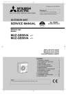
SPLIT-TYPE, HEAT PUMP AIR CONDITIONERS
E2
E1
has been added.
has been added.
Please void OB377
OUTDOOR UNIT
SERVICE MANUAL
HFC
utilized
No. OB377
REVISED EDITION-A
R410A
Inverter-controlled multi system type
Models
MXZ-2A40VA
MXZ-2A52VA
MXZ-3A54VA
MXZ-3A54VA
MXZ-4A71VA
MXZ-4A71VA
MXZ-4A80VA
-
E1
E1
E1
E2
E1
Indoor unit service manual
MSZ-FA•VA Series (OB371)
MSZ-GA•VA Series
(OB378,OB388)
MSZ-CB•VA Series (OB441)
E2
E1
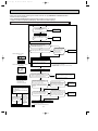
CONTENTS
MXZ-4A80VA
1. TECHNICAL CHANGES ····································2
2. PART NAMES AND FUNCTIONS······················7
3. INDOOR/OUTDOOR
CORRESPONDENCE TABLE ···························8
4. INDOOR UNITS COMBINATION ·····················10
5. SPECIFICATION···············································24
6. NOISE CRITERIA CURVES ·····························27
7. OUTLINES AND DIMENSIONS ·······················28
8. WIRING DIAGRAM ··········································31
9. REFRIGERANT SYSTEM DIAGRAM ··············35
10. PERFORMANCE CURVES ······························39
11. ACTUATOR CONTROL ····································50
12. SERVICE FUNCTIONS·····································50
13. TROUBLESHOOTING······································53
14. DISASSEMBLY INSTRUCTIONS·····················77
15. PARTS LIST······················································86
16. OPTIONAL PARTS ······················BACK COVER
NOTE:
•This service manual describes technical data of outdoor units.
OB377--1.qxp
05.12.14 3:17 PM
Page 2
Revision : A
• MXZ-3A54/4A71VA- E2 has been added.
Quick clean kit has been removed.(Refer to 2)
• MXZ-2A40/52VA- E1 has been added.
1
TECHNICAL CHANGES
MXZ-A26WV - E1 ➔ MXZ-3A54VA - E1
1. Indication of capacity has been changed. (BTU➔kW)
2. Capacity specification has been changed. (Cooling capacity 7.1kW➔5.4kW)
3. Dimensions of unit has been changed. (W900oH900oD320➔W840oH710oD330)
4. Combinations of connectable indoor units have been changed.
5. Capacity class of connectable indoor units have been changed.
6. Communication system has been changed.
7. Power supply way has been changed(change to supply to outdoor unit).
8. Compressor has been changed. (TNB220FMCH➔SNB130FLDH1)
9. High-pressure switch has been removed.
10.Outdoor fan motor has been changed. (PM8H60-UA➔RC0J60-AA)
11.Evaporation temperature thermistor has been removed.
12.Ambient temperature thermistor has been added.
13.New dip switch has been added to the controller board for "Locking the operation "mode
and "Lowering the operating noise "mode.
14.A Quick Clean Kit has been added.
MXZ-A32WV - E1 ➔ MXZ-4A71VA - E1
1. Indication of capacity has been changed. (BTU➔kW)
2. Capacity specification has been changed. (Cooling capacity 8.0kW➔7.1kW)
3. Dimensions of unit has been changed. (W900oH900oD320➔W840oH710oD330)
4. Combinations of connectable indoor units have been changed.
5. Capacity class of connectable indoor units have been changed.
6. Communication system has been changed.
7. Power supply way has been changed(change to supply to outdoor unit).
8. Compressor has been changed. (TNB220FMCH➔SNB130FLDH1)
9. High-pressure switch has been removed.
10. Outdoor fan motor has been changed. (PM8H60-U➔RC0J60-AA)
11. Evaporation temperature thermistor has been removed.
12. Ambient temperature thermistor has been added.
13. New dip switch has been added to the controller board for "Locking the operation "mode
and "Lowering the operating noise "mode.
14. A Quick Clean Kit has been added.
MXZ-A32WV - E1 ➔ MXZ-4A80VA - E1
1. Indication of capacity has been changed. (BTU➔kW)
2. Communication system has been changed.
3. Power supply way has been changed(change to supply to outdoor unit).
4. Evaporation temperature thermistor has been removed.
5. Ambient temperature thermistor has been added.
6. New dip switch has been added to the controller board for "Locking the operation "mode
and "Lowering the operating noise "mode.
7. A Quick Clean Kit has been added.
2
OB377--1.qxp
05.12.14 3:17 PM
Page 3
MXZ-A14WV - E2 ➔ MXZ-2A40VA - E1
1. Indication of capacity has been changed. (BTU➔kW)
2. Dimensions of unit has been changed. (W840oH640oD330➔W800oH550oD285)
3. Communication system has been changed.
4. Power supply way has been changed(change to supply to outdoor unit).
5. Compressor has been changed. (SNV092FJYH➔SNB130FKCH)
6. Outdoor fan motor has been changed. (RA6V49➔RC0J50-CF)
7. Evaporation temperature thermistor has been removed.
8. Pas pipe temperature thermistor has been removed.
9. Ambient temperature thermistor has been added.
MXZ-A18WV - E2 ➔ MXZ-2A52VA - E1
1. Indication of capacity has been changed. (BTU➔kW)
2. Cooling capacity specification has been changed. (5.4kW➔5.2kW)
3. Heating capacity specification has been changed. (6.6kW➔6.4kW)
4. Dimensions of unit has been changed. (W840oH640oD330➔W800oH550oD285)
5. Communication system has been changed.
6. Power supply way has been changed(change to supply to outdoor unit).
7. Compressor has been changed. (SNV092FJYH➔SNB130FKCH)
8. Outdoor fan motor has been changed. (RA6V49➔RC0J50-CF)
9. Evaporation temperature thermistor has been removed.
10.Pas pipe temperature thermistor has been removed.
11. Ambient temperature thermistor has been added.
MXZ-3A54VA - E1 ➔ MXZ-3A54VA - E2
MXZ-4A71VA - E1 ➔ MXZ-4A71VA - E2
1. Quick clean kit has been removed.
3
OB377--1.qxp
05.12.14 3:17 PM
Page 4
INFORMATION FOR THE AIR CONDITIONER WITH R410A REFRIGERANT
• This room air conditioner adopts HFC refrigerant (R410A) which never destroys the ozone layer.
• Pay particular attention to the following points, though the basic installation procedure is same as that for R22 air conditioners.
1 As R410A has working pressure approximate 1.6 times as high as that of R22, some special tools and piping parts/
materials are required. Refer to the table below.
2 Take sufficient care not to allow water and other contaminations to enter the R410A refrigerant during storage and
installation, since it is more susceptible to contaminations than R22.
3 For refrigerant piping, use clean, pressure-proof parts/materials specifically designed for R410A. (Refer to 2. Refrigerant
piping.)
4 Composition change may occur in R410A since it is a mixed refrigerant. When charging, charge liquid refrigerant to prevent
composition change.
New refrigerant
R410A
R22
Composition (Ratio)
HFC-32: HFC-125 (50%:50%)
R22 (100%)
Refrigerant handling
Pseudo-azeotropic refrigerant
Single refrigerant
Not included
Included
Refrigerant
Chlorine
A1/A1
A1
72.6
86.5
Boiling point (:)
-51.4
-40.8
Steam pressure [25:](Mpa)
1.557
0.94
64
44.4
Non combustible
Non combustible
0
0.055
Refrigerant
Safety group (ASHRAE)
Molecular weight
Saturated steam density [25:](Kg/K)
Combustibility
ODP w1
GWP w2
Refrigerant charge method
1730
1700
From liquid phase in cylinder
Gas phase
Possible
Possible
Kind
Incompatible oil
Compatible oil
Color
Non
Light yellow
Non
Non
oil
Refrigeration
Additional charge on leakage
Smell
w1 :Ozone Destruction Parameter : based on CFC-11
w2 :Global Warmth Parameter
: based on CO2
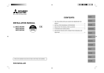
New Specification
Compressor
Previous refrigerant
Current Specification
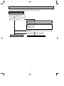
The incompatible refrigeration oil easily separates from
Since refrigerant and refrigerantion oil are compatible each,
refrigerant and is in the upper layer inside the suction muffler. refrigeration oil goes back to the compressor through the
Raising position of the oil back hole enables to back the
lower position oil back hole.
refrigeration oil of the upper layer to flow back to the
compressor.
Suction muffler
Suction muffler
Compressor
Oil back hole
Compressor
Refrigeration oil
Oil back hole
Refrigerant
Refrigeration oil /Refrigerant
NOTE : The unit of pressure has been changed to MPa on the international system of units(SI unit system).
f [Gauge])
The conversion factor is: 1(MPa [Gauge]) =10.2(kgf/f
4
OB377--1.qxp
05.12.14 3:17 PM
Page 5
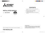
Conversion chart of refrigerant temperature and pressure
(MPa [Gauge])
4.0
Saturated liquid pressure
3.5
R410A
3.0
R22
2.5
2.0
NOTE : The unit of pressure has been changed to MPa on the
international system of units(SI unit system).
1.5
1.0
f [Gauge])
The conversion factor is: 1(MPa [Gauge]) =10.2(kgf/f
0.5
0.0
-0.5
-30 -20 -10
0
10
20
30
40
50
60
(:)
1.Tools dedicated for the air conditioner with R410A refrigerant
The following tools are required for R410A refrigerant. Some R22 tools can be substituted for R410A tools.
The diameter of the service port on the stop valve in outdoor unit has been changed to prevent any other refrigerant being
charged into the unit. Cap size has been changed from 7/16 UNF with 20 threads to 1/2 UNF with 20 threads.
R410A tools
Description
Can R22 tools be used?
R410A has high pressures beyond the measurement range of existing
gauges. Port diameters have been changed to prevent any other refrigerant
from being charged into the unit.
Gauge manifold
No
Charge hose
No
Gas leak detector
No
Hose material and cap size have been changed to improve the pressure
resistance.
Dedicated for HFC refrigerant.
Yes
6.35 mm and 9.52 mm
No
12.7 mm and 15.88 mm
Flare tool
Yes
Clamp bar hole has been enlarged to reinforce the spring strength in the tool.
Flare gauge
Vacuum pump
adapter
Electronic scale for
refrigerant charging
New
Provided for flaring work (to be used with R22 flare tool).
Provided to prevent the back flow of oil. This adapter enables you to use
vacuum pumps.
It is difficult to measure R410A with a charging cylinder because the
refrigerant bubbles due to high pressure and high-speed vaporization
Torque wrench
New
New
No : Not Substitutable for R410A
Yes : Substitutable for R410A
2.Refrigerant piping
1 Specifications
Use the copper or copper-alloy seamless pipe for refrigerant that meet the following specifications.
Outside diameter
mm
Wall thickness
Insulation material
6.35
0.8 mm
9.52
0.8 mm
Heat resisting foam plastic
12.7
0.8 mm
Specific gravity 0.045 Thickness 8 mm
15.88
1.0 mm
5
OB377--1.qxp
05.12.14 3:17 PM
Page 6
2 Flaring work and flare nut
Flaring work for R410A pipe differs from that for R22 pipe.
For details of flaring work, refer to Installation manual “FLARING WORK”.
Dimension of flare nut
Pipe diameter
mm
R410A
R22
6.35
17
17
9.52
22
22
12.7
26
24
15.88
29
27
3.Refrigerant oil
Apply the special refrigeration oil (accessories: packed with indoor unit) to the flare and the union seat surfaces.
4.Air purge
• Do not discharge the refrigerant into the atmosphere.
Take care not to discharge refrigerant into the atmosphere during installation, reinstallation, or repairs to the refrigerant
circuit.
• Use the vacuum pump for air purging for the purpose of environmental protection.
5.Additional charge
For additional charging, charge the refrigerant from liquid phase of the gas cylinder.
If the refrigerant is charged from the gas phase, composition change may occur in the refrigerant inside the cylinder and the
outdoor unit. In this case, ability of the refrigeration cycle decreases or normal operation can be impossible. However,
charging the liquid refrigerant all at once may cause the compressor to be locked. Thus, charge the refrigerant slowly.
Union
Stop valve
Indoor unit
Liquid pipe
Outdoor unit
Gas pipe
Refrigerant gas
cylinder
operating valve
Service port
Gauge manifold
valve (for R410A)
Charge hose (for R410A)
Refrigerant gas cylinder
for R410A with siphon
Refrigerant (liquid)
Electronic scale for refrigerant charging
6
OB377--1.qxp
05.12.14 3:17 PM
2
Page 7
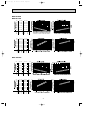
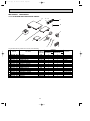
PART NAMES AND FUNCTIONS
MXZ-2A40VA
MXZ-2A52VA
MXZ-3A54VA
MXZ-4A71VA
Air inlet
(Back and side)
Air inlet
(back and side)
Piping
Drain hose
Air outlet
Air outlet
Drain outlet
Drain outlet
MXZ-4A80VA
Air inlet
(Back and side)
Air outlet
Drain outlet
ACCESSORIES
MXZ-2A40VA
MXZ-2A52VA
MXZ-3A54VA - E1
MXZ-4A71VA - E1
1 Drain socket
1
1
MXZ-3A54VA - E2
MXZ-4A71VA - E2
MXZ-4A80VA
1
2 Drain cap
−
2
2
3 Quick Clean kit
−
1
−
7
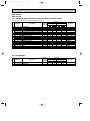
OB377--1.qxp
Combination of the
connectable indoor
units
3
05.12.14 3:17 PM
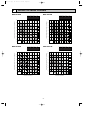
Page 8
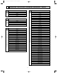
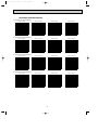
INDOOR/ OUTDOOR CORRESPONDENCE TABLE
MXZ-2A40VA
MXZ-4A71VA
22+22
22+25
22+35
25+25
25+35
22+22
22+25
22+35
22+50
22+60
25+25
25+35
25+50
25+60
35+35
35+50
35+60
50+50
50+60
60+60
22+22+22
22+22+25
22+22+35
22+22+50
22+22+60
22+25+25
22+25+35
22+25+50
22+25+60
22+35+35
22+35+50
22+35+60
22+50+50
25+25+25
25+25+35
25+25+50
25+25+60
25+35+35
25+35+50
25+35+60
25+50+50
35+35+35
35+35+50
22+22+22+22
22+22+22+25
22+22+22+35
22+22+22+50
22+22+25+25
22+22+25+35
22+22+25+50
22+22+35+35
22+25+25+25
22+25+25+35
22+25+25+50
25+25+35+35
22+25+35+35
25+25+25+25
25+25+25+35
25+25+25+50
22+22
22+25
22+35
25+25
25+35
35+35
Combination of the connectable indoor units
Combination of the
connectable indoor
units
MXZ-2A52VA
Combination of the connectable indoor units
MXZ-3A54VA
22+22
22+25
22+35
22+50
25+25
25+35
25+50
35+35
35+50
50+50
22+22+22
22+22+25
22+22+35
22+22+50
22+25+25
22+25+35
22+25+50
22+35+35
25+25+25
25+25+35
25+25+50
25+35+35
❈There is no combination other than this table.
8
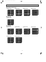
Page 9
MXZ-4A80VA
MXZ-4A80VA
22+22
22+25
22+35
22+50
22+60
22+71
25+25
25+35
25+50
25+60
25+71
35+35
35+50
35+60
35+71
50+50
50+60
50+71
60+60
60+71
22+22+22
22+22+25
22+22+35
22+22+50
22+22+60
22+22+71
22+25+25
22+25+35
22+25+50
22+25+60
22+25+71
22+35+35
22+35+50
22+35+60
22+35+71
22+50+50
22+50+60
22+50+71
25+25+25
25+25+35
25+25+50
25+25+60
25+25+71
25+35+35
25+35+50
25+35+60
25+35+71
25+50+50
25+50+60
35+35+35
35+35+50
35+35+60
35+35+71
35+50+50
35+50+60
22+22+22+22
22+22+22+25
22+22+22+35
22+22+22+50
22+22+22+60
22+22+22+71
22+22+25+25
22+22+25+35
22+22+25+50
22+22+25+60
22+22+25+71
22+22+35+35
22+22+35+50
22+22+35+60
22+22+50+50
22+25+25+25
22+25+25+35
22+25+25+50
22+25+25+60
22+25+35+35
22+25+35+50
22+25+35+60
22+35+35+35
22+35+35+50
25+25+25+25
25+25+25+35
25+25+25+50
25+25+25+60
25+25+35+35
25+25+35+50
25+35+35+35
35+35+35+35
Combination of the connectable indoor units
05.12.14 3:17 PM
Combination of the connectable indoor units
OB377--1.qxp
❈There is no combination other than this table.
9
OB377--1.qxp
05.12.14 3:17 PM
4
Page 10
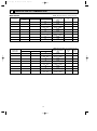
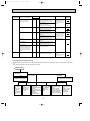
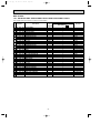
INDOOR UNITS COMBINATION
MXZ-2A40VA
Cooling capacity (kW)
Indoor units
combination
Unit A
22
2.20
25
2.50
35
3.50
22+22
1.90
1.90
22+25
1.83
2.07
22+35
1.51
2.39
25+25
1.95
1.95
25+35
1.67
2.33
Total
Unit B
2.2
(0.9 - 3.0)
2.5
(0.9 - 3.3)
3.5
(0.9 - 4.0)
3.8
( 1.1 - 4.3)
3.9
(1.1 - 4.3)
3.9
(1.1 - 4.4)
3.9
(1.1 - 4.4)
4.0
(1.1 - 4.5)
Heating capacity (kW)
Indoor units
combination
Unit A
22
3.30
25
3.60
35
4.00
22+22
2.20
2.20
22+25
2.06
2.34
22+35
1.70
2.70
25+25
2.20
2.20
25+35
1.85
2.65
Total
Unit B
3.3
(0.9 - 4.0)
3.6
(0.9 - 4.5)
4.0
(0.9 - 4.8)
4.4
(1.0 - 4.8)
4.4
(1.0 - 4.8)
4.4
(1.0 - 4.9)
4.4
(1.0 - 4.9)
4.5
(1.0 - 5.0)
10
NOTE: Electrical data is for outdoor unit only.
Outdoor unit
Power
Current
power consumption
factor
(A)
(kW)
(%)
0.430
2.08
90
(0.120 - 0.620)
0.490
2.37
90
(0.120 - 0.690)
0.730
3.53
90
(0.120 - 0.900)
0.830
3.80
95
(0.250 - 1.110)
0.970
4.44
95
(0.250 - 1.110)
0.970
4.44
95
(0.250 - 1.130)
0.970
4.44
95
(0.250 - 1.130)
1.045
4.78
95
(0.250 - 1.170)
NOTE: Electrical data is for outdoor unit only.
Outdoor unit
Power
Current
power consumption
factor
(A)
(kW)
(%)
0.670
3.24
90
(0.110 - 0.910)
0.730
3.53
90
(0.110 - 1.050)
0.870
4.20
90
(0.110 - 1.150)
0.910
4.16
95
(0.200 - 1.010)
0.910
4.16
95
( 0.200 - 1.010)
0.910
4.16
95
(0.200 - 1.030)
0.910
4.16
95
(0.200 - 1.030)
0.945
4.32
95
(0.200 - 1.050)
OB377--1.qxp
05.12.14 3:17 PM
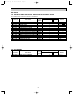
Page 11
MXZ-2A52VA
Cooling capacity (kW)
Indoor units
combination
Unit A
22
2.20
25
2.50
35
3.50
22+22
2.20
2.20
22+25
2.20
2.50
22+35
1.93
3.07
25+25
2.50
2.50
25+35
2.13
2.97
35+35
2.60
2.60
Total
Unit B
2.2
(0.9 - 3.0)
2.5
(0.9 - 3.3)
3.5
(0.9 - 4.0)
4.4
(1.1 - 5.3)
4.7
(1.1 - 5.4)
5.0
(1.1 - 5.6)
5.0
(1.1 - 5.6)
5.1
(1.1 - 5.8)
5.2
(1.1 - 6.0)
Heating capacity (kW)
Indoor units
combination
Unit A
22
3.30
25
3.60
35
4.00
22+22
3.05
3.05
22+25
2.90
3.30
22+35
2.43
3.87
25+25
3.15
3.15
25+35
2.63
3.67
35+35
3.20
3.20
Total
Unit B
3.3
( 0.9 - 4.0)
3.6
(0.9 - 4.5)
4.0
(0.9 - 4.8)
6.1
(1.0 - 6.7)
6.2
(1.0 - 6.8)
6.3
(1.0 - 7.0)
6.3
(1.0 - 7.0)
6.3
(1.0 - 7.1)
6.4
(1.0 - 7.2)
11
NOTE: Electrical data is for outdoor unit only.
Outdoor unit
Power
Current
power consumption
factor
(A)
(kW)
(%)
0.430
2.08
90
(0.120 - 0.620)
0.490
(0.120 - 0.690)
0.730
(0.120 - 0.900)
1.130
(0.250-1.510)
1.250
(0.250 - 1.560)
1.400
(0.250 - 1.650)
1.400
(0.250 - 1.650)
1.450
(0.250 - 1.740)
1.505
(0.250 - 1.830)
2.37
90
3.53
90
5.12
96
5.66
96
6.28
97
6.28
97
6.50
97
6.75
97
NOTE: Electrical data is for outdoor unit only.
Outdoor unit
Power
Current
power consumption
factor
(A)
(kW)
(%)
0.670
3.24
90
(0.110 - 0.910)
0.730
90
3.53
(0.110 - 1.050)
0.870
90
4.20
(0.110 - 1.150)
1.550
6.95
97
(0.200 - 1.730)
1.600
7.17
97
(0.200 - 1.750)
1.650
7.40
97
(0.200 - 1.790)
1.650
7.40
97
(0.200 - 1.790)
1.650
97
7.40
(0.200 - 1.820)
1.705
97
7.64
(0.200 - 1.840)
OB377--1.qxp
05.12.14 3:17 PM
Page 12
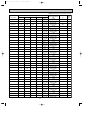
MXZ-3A54VA
Cooling capacity (kW)
Indoor units
combination
Unit A
22
2.2
25
2.5
35
3.5
50
5.0
22+22
2.2
2.2
22+25
2.2
2.5
22+35
2.08
3.32
22+50
1.65
3.75
25+25
2.5
2.5
25+35
2.25
3.15
25+50
1.8
3.6
35+35
2.7
2.7
35+50
2.22
3.18
50+50
2.7
2.7
22+22+22
1.8
1.8
1.8
22+22+25
1.72
1.72
1.96
22+22+35
1.5
1.5
2.4
22+22+50
1.26
1.26
2.88
22+25+25
1.64
1.88
1.88
22+25+35
1.45
1.65
2.3
22+25+50
1.23
1.39
2.78
22+35+35
1.3
2.05
2.05
25+25+25
1.8
1.8
1.8
25+25+35
1.59
1.59
2.22
25+25+50
1.35
1.35
2.7
25+35+35
1.42
1.99
1.99
Unit B
Total
Unit C
2.2
(1.4 - 3.0)
2.5
(1.4 - 3.3)
3.5
(1.5 - 4.3)
5.0
(1.6 - 5.6)
4.4
(2.0 - 5.4)
4.7
(2.0 - 5.8)
5.4
(2.0 - 6.8)
5.4
(2.0 - 6.8)
5.0
(2.0 - 6.0)
5.4
(2.0 - 6.8)
5.4
(2.0 - 6.8)
5.4
(2.0 - 6.8)
5.4
(2.0 - 6.8)
5.4
(2.1 - 6.8)
5.4
(2.9 - 6.8)
5.4
(2.9 - 6.8)
5.4
(2.9 - 6.8)
5.4
(2.9 - 6.8)
5.4
(2.9 - 6.8)
5.4
(2.9 - 6.8)
5.4
(2.9 - 6.8)
5.4
(2.9 - 6.8)
5.4
(2.9 - 6.8)
5.4
(2.9 - 6.8)
5.4
(2.9 - 6.8)
5.4
(2.9 - 6.8)
12
NOTE: Electrical data is for outdoor unit only.
Outdoor unit
Power
Current
power consumption
factor
(A)
(kW)
(%)
0.590
99
2.59
(0.420 - 0.740)
0.660
99
2.90
(0.420 - 0.830)
0.950
99
4.17
(0.430 - 1.180)
1.500
99
6.59
(0.480 - 1.660)
1.180
99
5.18
(0.540 - 1.450)
1.300
99
5.71
(0.540 - 1.630)
1.600
99
7.03
(0.540 - 2.550)
1.580
99
6.94
(0.550 - 2.440)
1.420
99
6.24
(0.540 - 1.750)
1.600
99
7.03
(0.540 - 2.550)
1.580
(0.550 - 2.440)
1.600
(0.540 - 2.550)
1.530
(0.550 - 2.440)
1.550
(0.560 - 2.340)
1.295
(0.670 - 1.770)
1.295
(0.670 - 1.770)
1.295
(0.670 - 1.770)
1.265
(0.680 - 1.790)
1.295
(0.670 - 1.770)
1.295
(0.670 - 1.770)
1.265
(0.680 - 1.790)
1.295
(0.670 - 1.770)
1.295
(0.670 - 1.770)
1.295
(0.670 - 1.770)
1.265
(0.680 - 1.790)
1.295
(0.670 - 1.770)
6.94
99
7.03
99
6.72
99
6.81
99
5.69
99
5.69
99
5.69
99
5.56
99
5.69
99
5.69
99
5.56
99
5.69
99
5.69
99
5.69
99
5.56
99
5.69
99
OB377--1.qxp
05.12.14 3:17 PM
Page 13
Heating capacity (kW)
Indoor units
combination
Unit A
22
3.3
25
3.6
35
4.0
50
6.8
22+22
3.3
3.3
22+25
3.18
3.62
22+35
2.62
4.18
22+50
2.08
4.72
25+25
3.4
3.4
25+35
2.83
3.97
25+50
2.27
4.53
35+35
3.4
3.4
35+50
2.8
4.0
50+50
3.4
3.4
22+22+22
2.27
2.27
2.27
22+22+25
2.17
2.17
2.46
22+22+35
1.89
1.89
3.02
22+22+50
1.59
1.59
3.62
22+25+25
2.08
2.36
2.36
22+25+35
1.83
2.07
2.9
22+25+50
1.54
1.75
3.51
22+35+35
1.62
2.59
2.59
25+25+25
2.27
2.27
2.27
25+25+35
2.0
2.0
2.8
25+25+50
1.7
1.7
3.4
25+35+35
1.78
2.51
2.51
Unit B
Total
Unit C
3.3
(1.2 - 4.2)
3.6
(1.2 - 4.5)
4.0
(1.2 - 4.8)
6.8
(1.4 - 8.2)
6.6
(1.8 - 7.2)
6.8
(1.8 - 8.7)
6.8
(1.8 - 9.0)
6.8
(1.8 - 9.0)
6.8
(1.8 - 9.0)
6.8
(1.8 - 9.0)
6.8
(1.8 - 9.0)
6.8
(1.8 - 9.0)
6.8
(1.8 - 9.0)
6.8
(1.9 - 9.0)
6.8
(2.6 - 9.0)
6.8
(2.6 - 9.0)
6.8
(2.6 - 9.0)
6.8
(2.6 - 9.0)
6.8
(2.6 - 9.0)
6.8
(2.6 - 9.0)
6.8
(2.6 - 9.0)
6.8
(2.6 - 9.0)
6.8
(2.6 - 9.0)
6.8
(2.6 - 9.0)
6.8
(2.6 - 9.0)
6.8
(2.6 - 9.0)
13
NOTE: Electrical data is for outdoor unit only.
Outdoor unit
Power
Current
power consumption
factor
(A)
(kW)
(%)
0.820
99
3.60
(0.380 - 1.090)
0.910
(0.380 - 1.190)
1.040
(0.380 - 1.300)
1.770
(0.370 - 2.300)
1.500
(0.410 - 1.710)
1.580
(0.410 - 2.350)
1.580
(0.410 - 2.390)
1.440
(0.390 - 2.220)
1.580
(0.410 - 2.390)
1.580
(0.410 - 2.390)
1.440
(0.390 - 2.220)
1.580
(0.410 - 2.390)
1.440
(0.410 - 2.220)
1.390
(0.360 - 2.040)
1.455
(0.500 - 2.120)
1.455
(0.500 - 2.120)
1.455
(0.500 - 2.120)
1.310
(0.480 - 1.960)
1.455
(0.500 - 2.120)
1.455
(0.500 - 2.120)
1.310
(0.480 - 1.960)
1.455
(0.500 - 2.120)
1.455
(0.500 - 2.120)
1.455
(0.500 - 2.120)
1.310
(0.480 - 1.960)
1.455
(0.460 - 2.120)
4.00
99
4.57
99
7.77
99
6.59
99
6.94
99
6.94
99
6.32
99
6.94
99
6.94
99
6.32
99
6.94
99
6.32
99
6.10
99
6.39
99
6.39
99
6.39
99
5.75
99
6.39
99
6.39
99
5.75
99
6.39
99
6.39
99
6.39
99
5.75
99
6.39
99
OB377--1.qxp
05.12.14 3:17 PM
Page 14
MXZ-4A71VA
Cooling capacity (kW)
Indoor units
combination
Unit A
22
2.2
25
2.5
35
3.5
50
5.0
60
6.0
22+22
2.2
2.2
22+25
2.2
2.5
22+35
2.2
3.5
22+50
2.08
4.72
22+60
1.82
4.98
25+25
2.5
2.5
25+35
2.5
3.5
25+50
2.27
4.53
25+60
2.0
4.8
35+35
3.4
3.4
35+50
2.8
4.0
35+60
2.51
4.29
50+50
3.4
3.4
50+60
3.09
3.71
60+60
3.4
3.4
22+22+22
2.2
2.2
2.2
22+22+25
2.2
2.2
2.5
22+22+35
1.98
1.98
3.14
22+22+50
1.66
1.66
3.78
22+22+60
1.5
1.5
4.1
22+25+25
2.16
2.47
2.47
22+25+35
1.91
2.16
3.03
22+25+50
1.61
1.83
3.66
22+25+60
1.46
1.66
3.98
22+35+35
1.7
2.7
2.7
22+35+50
1.46
2.32
3.32
22+35+60
1.34
2.12
3.64
22+50+50
1.28
2.91
2.91
25+25+25
2.36
2.36
2.36
Unit B
Unit C
Unit D
Total
2.2
(1.4 - 3.0)
2.5
(1.4 - 3.3)
3.5
(1.5 - 4.3)
5.0
(1.6 - 5.6)
6.0
(1.6 - 6.0)
4.4
(2.0 - 5.4)
4.7
(2.0 - 5.8)
5.7
(2.0 - 6.6)
6.8
(2.0 - 7.1)
6.8
(2.0 - 7.1)
5.0
(2.0 - 6.0)
6.0
(2.0 - 7.1)
6.8
(2.0 - 7.1)
6.8
(2.0 - 7.1)
6.8
(2.0 - 7.1)
6.8
(2.0 - 7.1)
6.8
(2.0 - 7.1)
6.8
(2.1 - 7.1)
6.8
(2.1 -7.1)
6.8
(2.1 - 7.1)
6.6
(2.9 - 8.1)
6.9
(2.9 - 8.3)
7.1
(2.9 - 8.5)
7.1
(2.9 - 8.5)
7.1
(2.9 - 8.5)
7.1
(2.9 - 8.5)
7.1
(2.9 - 8.5)
7.1
(2.9 - 8.5)
7.1
(2.9 - 8.5)
7.1
(2.9 - 8.5)
7.1
(2.9 - 8.5)
7.1
(2.9 - 8.5)
7.1
(2.9 - 8.5)
7.1
(2.9 - 8.5)
14
NOTE: Electrical data is for outdoor unit only.
Outdoor unit
Power
Current
power consumption
factor
(A)
(kW)
(%)
0.590
2.59
99
(0.420 - 0.740)
0.660
2.90
99
(0.420 - 0.830)
0.950
4.17
99
(0.430 - 1.180)
1.500
6.59
99
(0.480 - 1.660)
2.110
9.27
99
(0.480 - 2.290)
1.180
5.18
99
(0.540 - 1.450)
1.300
5.71
99
(0.540 - 1.630)
1.800
7.91
99
(0.540 - 2.100)
2.440
10.72
99
(0.550 - 2.570)
2.460
10.80
99
(0.550 - 2.600)
1.420
(0.540 - 1.750)
2.010
(0.540 - 2.540)
2.440
(0.550 - 2.590)
2.460
(0.550 - 2.600)
2.570
(0.540 - 2.550)
2.440
(0.550 - 2.600)
2.460
(0.550 - 2.610)
2.380
(0.560 - 2.610)
2.400
(0.570 - 2.620)
2.420
(0.580 - 2.630)
1.750
(0.670 - 2.390)
1.880
(0.670 - 2.510)
1.990
(0.670 - 2.690)
1.960
(0.680 - 2.720)
1.950
(0.680 - 2.740)
1.990
(0.670 - 2.690)
1.990
(0.670 - 2.690)
1.960
(0.680 - 2.720)
1.950
(0.680 - 2.740)
1.990
(0.670 - 2.690)
1.960
(0.680 - 2.720)
1.950
(0.680 - 2.740)
1.940
(0.690 - 2.770)
1.990
(0.670 - 2.690)
6.24
99
8.83
99
10.72
99
10.80
99
11.29
99
10.72
99
10.80
99
10.45
99
10.54
99
10.63
99
7.69
99
8.26
99
8.74
99
8.61
99
8.56
99
8.74
99
8.74
99
8.61
99
8.56
99
8.74
99
8.61
99
8.56
99
8.52
99
8.74
99
OB377--1.qxp
05.12.14 3:17 PM
Page 15
Cooling capacity (kW)
Indoor units
combination
Unit A
Unit B
Unit C
25+25+35
2.09
2.09
2.92
25+25+50
1.78
1.78
3.54
25+25+60
1.61
1.61
3.88
25+35+35
1.86
2.62
2.62
25+35+50
1.61
2.26
3.23
25+35+60
1.48
2.07
3.55
25+50+50
1.42
2.84
2.84
35+35+35
2.36
2.36
2.36
35+35+50
2.07
2.07
2.96
22+22+22+22
1.77
1.77
1.77
1.77
22+22+22+25
1.72
1.72
1.72
1.94
22+22+22+35
1.55
1.55
1.55
2.45
22+22+22+50
1.35
1.35
1.35
3.05
22+22+25+25
1.66
1.66
1.89
1.89
22+22+25+35
1.5
1.5
1.71
2.39
22+22+25+50
1.31
1.31
1.5
2.98
22+22+35+35
1.37
1.37
2.18
2.18
22+25+25+25
1.61
1.83
1.83
1.83
22+25+25+35
1.46
1.66
1.66
2.32
22+25+25+50
1.29
1.45
1.45
2.91
22+25+35+35
1.34
1.52
2.12
2.12
25+25+25+25
1.77
1.77
1.77
1.77
25+25+25+35
1.61
1.61
1.61
2.27
25+25+25+50
1.42
1.42
1.42
2.84
25+25+35+35
1.48
1.48
2.07
2.07
Unit D
15
Total
7.1
(2.9 - 8.5)
7.1
(2.9 - 8.5)
7.1
(2.9 - 8.5)
7.1
(2.9 - 8.5)
7.1
(2.9 - 8.5)
7.1
(2.9 - 8.5)
7.1
(2.9 - 8.5)
7.1
(2.9 - 8.5)
7.1
(2.9 - 8.5)
7.1
(3.7 - 8.8)
7.1
(3.7 - 8.8)
7.1
(3.7 - 8.8)
7.1
(3.7 - 8.8)
7.1
(3.7 - 8.8)
7.1
(3.7 - 8.8)
7.1
(3.7 - 8.8)
7.1
(3.7 - 8.8)
7.1
(3.7 - 8.8)
7.1
(3.7 - 8.8)
7.1
(3.7 - 8.8)
7.1
(3.7 - 8.8)
7.1
(3.7 - 8.8)
7.1
(3.7 - 8.8)
7.1
(3.7 - 8.8)
7.1
(3.7 - 8.8)
NOTE: Electrical data is for outdoor unit only.
Outdoor unit
Power
Current
power consumption
factor
(A)
(kW)
(%)
1.99
99
8.74
(0.670 - 2.690)
1.96
(0.680 - 2.720)
1.95
(0.680 - 2.740)
1.99
(0.670 - 2.690)
1.96
(0.680 - 2.720)
1.95
(0.680 - 2.740)
1.94
(0.690 - 2.770)
1.99
(0.670 - 2.690)
1.96
(0.680 - 2.720)
1.95
(0.800 - 2.750)
1.95
(0.800 - 2.750)
1.95
(0.800 - 2.750)
1.91
(0.810 - 2.780)
1.95
(0.800 - 2.750)
1.95
(0.800 - 2.750)
1.91
(0.810 - 2.780)
1.95
(0.800 - 2.750)
1.95
(0.800 - 2.750)
1.95
(0.800 - 2.750)
1.91
(0.810 - 2.780)
1.95
(0.800 - 2.750)
1.95
(0.800 - 2.750)
1.95
(0.800 - 2.750)
1.91
(0.810 - 2.780)
1.95
(0.800 - 2.750)
8.61
99
8.56
99
8.74
99
8.61
99
8.56
99
8.52
99
8.74
99
8.61
99
8.56
99
8.56
99
8.56
99
8.39
99
8.56
99
8.56
99
8.39
99
8.56
99
8.56
99
8.56
99
8.39
99
8.56
99
8.56
99
8.56
99
8.39
99
8.56
99
OB377--1.qxp
05.12.14 3:17 PM
Page 16
Heating capacity (kW)
Indoor units
combination
Unit A
22
3.3
25
3.6
35
4.0
50
7.2
60
7.9
22+22
3.3
3.3
22+25
3.23
3.67
22+35
2.82
4.48
22+50
2.63
5.97
22+60
2.31
6.29
25+25
3.6
3.6
25+35
3.17
4.43
25+50
2.87
5.73
25+60
2.53
6.07
35+35
4.3
4.3
35+50
3.54
5.06
35+60
3.17
5.43
50+50
4.3
4.3
50+60
3.91
4.69
60+60
4.3
4.3
22+22+22
2.87
2.87
2.87
22+22+25
2.74
2.74
3.12
22+22+35
2.39
2.39
3.82
22+22+50
2.01
2.01
4.58
22+22+60
1.82
1.82
4.96
22+25+25
2.62
2.99
2.99
22+25+35
2.31
2.62
3.67
22+25+50
1.95
2.22
4.43
22+25+60
1.77
2.01
4.82
22+35+35
2.06
3.27
3.27
22+35+50
1.77
2.81
4.02
22+35+60
1.62
2.57
4.41
22+50+50
1.56
3.52
3.52
25+25+25
2.86
2.86
2.86
Unit B
Unit C
Unit D
Total
3.3
(1.2 - 4.2)
3.6
(1.2 - 4.5)
4.0
(1.2 - 4.8)
7.2
(1.4 - 8.2)
7.9
(1.4 - 8.6)
6.6
(1.8 - 7.2)
6.9
(1.8 - 8.7)
7.3
(1.8 - 9.0)
8.6
(1.8 - 9.0)
8.6
(1.8 - 9.0)
7.2
(1.8 - 9.0)
7.6
(1.8 - 9.0)
8.6
(1.8 - 9.0)
8.6
(1.8 - 9.0)
8.6
(1.8 - 9.0)
8.6
(1.8 - 9.0)
8.6
(1.8 - 9.0)
8.6
(1.9 - 9.0)
8.6
(1.9 - 9.0)
8.6
(1.9 - 9.0)
8.6
(2.6 - 9.0)
8.6
(2.6 - 9.0)
8.6
(2.6 - 9.0)
8.6
(2.6 - 9.0)
8.6
(2.6 - 9.0)
8.6
(2.6 - 9.0)
8.6
(2.6 - 9.0)
8.6
(2.6 - 9.0)
8.6
(2.6 - 9.0)
8.6
(2.6 - 9.0)
8.6
(2.6 - 9.0)
8.6
(2.6 - 9.0)
8.6
(2.6 - 9.0)
8.6
(2.6 - 9.0)
16
NOTE: Electrical data is for outdoor unit only.
Outdoor unit
Power
Current
power consumption
factor
(A)
(kW)
(%)
0.820
3.60
99
(0.380 - 1.090)
0.910
4.00
99
(0.380 - 1.190)
1.040
4.57
99
(0.380 - 1.300)
1.880
8.26
99
(0.370 - 2.300)
2.150
9.44
99
(0.360 - 2.410)
1.500
6.59
99
(0.410 - 1.710)
1.610
7.07
99
(0.410 - 2.350)
1.770
7.77
99
(0.410 - 2.390)
2.110
9.27
99
(0.390 - 2.220)
2.090
9.18
99
(0.380 - 2.220)
1.710
7.51
99
(0.410 - 2.390)
1.890
8.30
99
(0.410 - 2.390)
2.110
9.27
99
(0.390 - 2.220)
2.090
9.18
99
(0.380 - 2.220)
2.030
8.92
99
(0.410 - 2.390)
2.110
9.27
99
(0.390 - 2.220)
2.090
9.18
99
(0.380 - 2.220)
1.820
7.99
99
(0.360 - 2.040)
1.820
7.99
99
(0.360 - 2.040)
1.820
7.99
99
(0.360 - 2.040)
2.020
8.87
99
(0.500 - 2.120)
2.020
8.87
99
(0.500 - 2.120)
2.020
8.87
99
(0.500 - 2.120)
1.860
8.17
99
(0.480 - 1.996)
1.850
8.12
99
(0.480 - 1.960)
2.020
(0.500 - 2.120)
2.020
(0.500 - 2.120)
1.860
(0.480 - 1.960)
1.850
(0.480 - 1.960)
2.020
(0.500 - 2.120)
1.860
(0.480 - 1.960)
1.850
(0.480 - 1.960)
1.670
(0.460 - 1.830)
2.020
(0.500 - 2.120)
8.87
99
8.87
99
8.17
99
8.12
99
8.87
99
8.17
99
8.12
99
7.33
99
8.87
99
OB377--1.qxp
05.12.14 3:17 PM
Page 17
Heating capacity (kW)
Indoor units
combination
Unit A
Unit B
Unit C
25+25+35
2.53
2.53
3.54
25+25+50
2.15
2.15
4.3
25+25+60
1.95
1.95
4.68
25+35+35
2.26
3.17
3.17
25+35+50
1.95
2.74
3.91
25+35+60
1.79
2.51
4.3
25+50+50
1.72
3.44
3.44
35+35+35
2.86
2.86
2.86
35+35+50
2.51
2.51
3.58
22+22+22+22
2.15
2.15
2.15
2.15
22+22+22+25
2.08
2.08
2.08
2.36
22+22+22+35
1.87
1.87
1.87
2.98
22+22+22+50
1.63
1.63
1.63
3.71
22+22+25+25
2.01
2.01
2.29
2.29
22+22+25+35
1.82
1.82
2.07
2.89
22+22+25+50
1.59
1.59
1.81
3.61
22+22+35+35
1.66
1.66
2.64
2.64
22+25+25+25
1.94
2.22
2.22
2.22
22+25+25+35
1.77
2.01
2.01
2.81
22+25+25+50
1.56
1.76
1.76
3.52
22+25+35+35
1.62
1.84
2.57
2.57
25+25+25+25
2.15
2.15
2.15
2.15
25+25+25+35
1.95
1.95
1.95
2.75
25+25+25+50
1.72
1.72
1.72
3.44
25+25+35+35
1.79
1.79
2.51
2.51
Unit D
17
Total
8.6
(2.6 - 9.0)
8.6
(2.6 - 9.0)
8.6
(2.6 - 9.0)
8.6
(2.6 - 9.0)
8.6
(2.6 - 9.0)
8.6
(2.6 - 9.0)
8.6
(2.6 - 9.0)
8.6
(2.6 - 9.0)
8.6
(2.6 - 9.0)
8.6
(3.4 - 9.0)
8.6
(3.4 - 9.0)
8.6
(3.4 - 9.0)
8.6
(3.4 - 9.0)
8.6
(3.4 - 9.0)
8.6
(3.4 - 9.0)
8.6
(3.4 - 9.0)
8.6
(3.4 - 9.0)
8.6
(3.4 - 9.0)
8.6
(3.4 - 9.0)
8.6
(3.4 - 9.0)
8.6
(3.4 - 9.0)
8.6
(3.4 - 9.0)
8.6
(3.4 - 9.0)
8.6
(3.4 - 9.0)
8.6
(3.4 - 9.0)
NOTE: Electrical data is for outdoor unit only.
Outdoor unit
Power
Current
power consumption
factor
(A)
(kW)
(%)
2.020
99
8.87
(0.500 - 2.120)
1.860
99
8.17
(0.480 - 1.996)
1.850
99
8.12
(0.480 - 1.960)
2.020
99
8.87
(0.500 - 2.120)
1.860
99
8.17
(0.480 - 1.960)
1.850
99
8.12
(0.480 - 1.960)
1.670
99
7.33
(0.460 - 1.830)
2.020
99
8.87
(0.500 - 2.120)
1.860
8.17
99
(0.500- 1.960)
1.930
99
8.48
(0.600 - 1.960)
1.930
99
8.48
(0.600 - 1.960)
1.930
99
8.48
(0.600 - 1.960)
1.770
99
7.77
(0.600 - 1.930)
1.930
99
8.48
(0.600 - 1.960)
1.930
99
8.48
(0.600 - 1.960)
1.770
7.77
99
(0.600 - 1.930)
1.930
99
8.48
(0.600 - 1.960)
1.930
99
8.48
(0.600 - 1.960)
1.930
99
8.48
(0.600 - 1.960)
1.770
99
7.77
(0.600 - 1.930)
1.930
8.48
99
(0.600 - 1.960)
1.930
99
8.48
(0.600 - 1.960)
1.930
99
8.48
(0.600 - 1.960)
1.770
99
7.77
(0.600 - 1.930)
1.930
99
8.48
(0.600 - 1.960)
OB377--1.qxp
05.12.14 3:17 PM
Page 18
MXZ-4A80VA
Cooling capacity (kW)
Indoor units
combination
Unit A
Unit B
Unit C
Unit D
22
2.2
–
–
–
25
2.5
–
–
–
35
3.5
–
–
–
50
5.0
–
–
–
60
6.0
–
–
–
71
7.1
–
–
–
22+22
2.2
2.2
–
–
22+25
2.2
2.5
–
–
22+35
2.2
3.5
–
–
22+50
2.2
5.0
–
–
22+60
1.75
6.0
–
–
22+71
1.66
6.19
–
–
25+25
2.5
2.5
–
–
25+35
2.5
3.5
–
–
25+50
2.5
5.0
–
–
25+60
2.11
5.64
–
–
25+71
2.01
5.84
–
–
35+35
3.5
3.5
–
–
35+50
3.1
4.65
–
–
35+60
2.61
5.24
–
–
35+71
2.51
5.44
–
–
50+50
3.95
3.95
–
–
50+60
3.42
4.57
–
–
50+71
3.27
4.72
–
–
60+60
4.0
4.0
–
–
60+71
3.84
4.16
–
–
22+22+22
2.2
2.2
2.2
–
22+22+25
2.2
2.2
2.5
–
22+22+35
2.14
2.14
3.42
–
22+22+50
1.72
1.72
4.41
–
22+22+60
1.46
1.46
5.03
–
22+22+71
1.4
1.4
5.2
–
22+25+25
2.2
2.5
2.5
–
22+25+35
2.08
2.36
3.31
–
Total
2.2
(1.4-3.0)
2.5
(1.4-3.3)
3.5
(1.5-4.3)
5.0
(1.6-5.6)
6.0
(1.6-6.6)
7.1
(1.7-7.4)
4.4
(2.0-5.4)
4.7
(2.0-5.8)
5.7
(2.0-6.6)
7.2
(2.0-7.7)
7.75
(2.0-8.0)
7.85
(2.0-8.2)
5.0
(2.0-6.2)
6.0
(2.0-7.1)
7.5
(2.0-8.5)
7.75
(2.0-8.6)
7.85
(2.0-8.7)
7.0
(2.0-7.1)
7.75
(2.0-8.8)
7.85
(2.0-8.8)
7.95
(2.0-8.8)
7.9
(2.1-8.8)
8.0
(2.1-8.8)
8.0
(2.1-8.8)
8.0
(2.1-8.8)
8.0
(2.1-8.8)
6.6
(2.9-8.1)
6.9
(2.9-8.3)
7.7
(2.9-9.0)
7.85
(2.9-9.0)
7.95
(2.9-9.0)
8.0
(2.9-9.0)
7.2
(2.9-8.9)
7.75
(2.9-9.0)
18
NOTE: Electrical data is for outdoor unit only.
Outdoor unit
Power
Current
power consumption
factor
(A)
(kW)
(%)
0.680
2.99
99
(0.400-0.920)
0.760
3.34
99
(0.400-1.010)
1.030
4.52
99
(0.400-1.290)
1.440
6.32
99
(0.420-1.630)
1.930
8.48
99
(0.400-2.130)
2.580
11.33
99
(0.410-2.710)
1.130
4.96
99
(0.600-1.600)
1.270
5.58
99
(0.600-1.770)
1.710
7.51
99
(0.600-2.200)
2.450
10.76
99
(0.560-2.710)
2.750
(0.560-3.050)
2.810
(0.560-3.200)
1.360
(0.580-1.950)
2.010
(0.540-2.540)
2.580
(0.560-3.200)
2.750
(0.560-3.280)
2.810
(0.560-3.320)
2.400
(0.540-2.550)
2.760
(0.560-3.220)
2.730
(0.560-3.180)
2.780
(0.560-3.180)
2.780
(0.590-3.160)
2.800
(0.570-3.120)
2.800
(0.570-3.120)
2.690
(0.550-3.080)
2.690
(0.550-3.080)
1.860
(0.690-2.410)
1.970
(0.670-2.510)
2.310
(0.690-2.970)
2.320
(0.700-2.920)
2.370
(0.680-2.880)
2.390
(0.680-2.880)
2.100
(0.690-2.940)
2.350
(0.690-2.970)
12.08
99
12.34
99
5.97
99
8.83
99
11.33
99
12.08
99
12.34
99
10.54
99
12.12
99
11.99
99
12.21
99
12.21
99
12.30
99
12.30
99
11.81
99
11.81
99
8.17
99
8.65
99
10.14
99
10.19
99
10.41
99
10.50
99
9.22
99
10.32
99
OB377--1.qxp
05.12.14 3:17 PM
Page 19
Cooling capacity (kW)
Indoor units
combination
Unit A
Unit B
Unit C
Unit D
22+25+50
1.79
2.04
4.07
–
22+25+60
1.64
1.87
4.49
–
22+25+71
1.49
1.69
4.82
–
22+35+35
1.87
2.99
2.99
–
22+35+50
1.63
2.58
3.69
–
22+35+60
1.5
2.4
4.1
–
22+35+71
1.38
2.18
4.44
–
22+50+50
1.44
3.28
3.28
–
22+50+60
1.33
3.03
3.64
–
22+50+71
1.23
2.8
3.97
–
25+25+25
2.5
2.5
2.5
–
25+25+35
2.28
2.28
3.19
–
25+25+50
1.98
1.98
3.94
–
25+25+60
1.82
1.82
4.36
–
25+25+71
1.65
1.65
4.7
–
25+35+35
2.07
2.89
2.89
–
25+35+50
1.82
2.54
3.64
–
25+35+60
1.67
2.33
4.0
–
25+35+71
1.53
2.14
4.33
–
25+50+50
1.6
3.2
3.2
–
25+50+60
1.48
2.96
3.56
–
35+35+35
2.65
2.65
2.65
–
35+35+50
2.33
2.33
3.34
–
35+35+60
2.15
2.15
3.7
–
35+35+71
1.99
1.99
4.02
–
35+50+50
2.08
2.96
2.96
–
35+50+60
1.93
2.76
3.31
–
22+22+22+22
1.95
1.95
1.95
1.95
22+22+22+25
1.9
1.9
1.9
2.15
22+22+22+35
1.73
1.73
1.73
2.76
22+22+22+50
1.52
1.52
1.52
3.44
22+22+22+60
1.4
1.4
1.4
3.81
22+22+22+71
1.28
1.28
1.28
4.16
22+22+25+25
1.87
1.87
2.13
2.13
19
Total
7.9
(2.9-9.0)
8.0
(2.9-9.0)
8.0
(2.9-9.0)
7.85
(2.9-9.0)
7.9
(2.9-9.0)
8.0
(2.9-9.0)
8.0
(2.9-9.0)
8.0
(2.9-9.0)
8.0
(2.9-9.0)
8.0
(2.9-9.0)
7.5
(2.9-9.0)
7.75
(2.9-9.0)
7.9
(2.9-9.0)
8.0
(2.9-9.0)
8.0
(2.9-9.0)
7.85
(2.9-9.0)
8.0
(2.9-9.0)
8.0
(2.9-9.0)
8.0
(2.9-9.0)
8.0
(2.9-9.0)
8.0
(2.9-9.0)
7.95
(2.9-9.0)
8.0
(2.9-9.0)
8.0
(2.9-9.0)
8.0
(2.9-9.0)
8.0
(2.9-9.0)
8.0
(2.9-9.0)
7.8
(3.7-9.2)
7.85
(3.7-9.2)
7.95
(3.7-9.2)
8.0
(3.7-9.2)
8.0
(3.7-9.2)
8.0
(3.7-9.2)
7.85
(3.7-9.2)
NOTE: Electrical data is for outdoor unit only.
Outdoor unit
Power
Current
power consumption
factor
(A)
(kW)
(%)
2.370
10.41
99
(0.700-2.920)
2.390
10.50
99
(0.680-2.880)
2.390
(0.680-2.880)
2.350
(0.690-2.920)
2.320
(0.700-2.890)
2.350
(0.680-2.860)
2.350
(0.680-2.860)
2.330
(0.680-2.860)
2.300
(0.660-2.830)
2.300
(0.660-2.830)
2.250
(0.690-3.010)
2.350
(0.690-2.970)
2.370
(0.700-2.920)
2.390
(0.680-2.880)
2.390
(0.680-2.880)
2.350
(0.690-2.920)
2.380
(0.700-2.890)
2.350
(0.680-2.860)
2.350
(0.680-2.860)
2.330
(0.660-2.840)
2.300
(0.660-2.830)
2.280
(0.720-2.910)
2.280
(0.700-2.870)
2.260
(0.680-2.840)
2.260
(0.680-2.840)
2.240
(0.680-2.840)
2.220
(0.660-2.810)
2.180
(0.810-2.670)
2.190
(0.810-2.670)
2.210
(0.810-2.650)
2.150
(0.790-2.620)
2.130
(0.770-2.590)
2.130
(0.770-2.590)
2.190
(0.810-2.670)
10.50
99
10.32
99
10.19
99
10.32
99
10.32
99
10.23
99
10.10
99
10.10
99
9.88
99
10.32
99
10.41
99
10.50
99
10.50
99
10.32
99
10.45
99
10.32
99
10.32
99
10.23
99
10.10
99
10.01
99
10.01
99
9.93
99
9.93
99
9.84
99
9.75
99
9.57
99
9.62
99
9.71
99
9.44
99
9.35
99
9.35
99
9.62
99
OB377--1.qxp
05.12.14 3:17 PM
Page 20
Cooling capacity (kW)
Indoor units
combination
Unit A
Unit B
Unit C
Unit D
22+22+25+35
1.68
1.68
1.91
1.91
22+22+25+50
1.48
1.48
1.68
3.36
22+22+25+60
1.36
1.36
1.55
3.73
22+22+25+71
1.26
1.26
1.43
4.05
22+22+35+35
1.54
1.54
2.46
2.46
22+22+35+50
1.36
1.36
2.18
3.1
22+22+35+60
1.12
1.12
1.92
3.84
22+22+50+50
1.22
1.22
2.78
2.78
22+25+25+25
1.78
2.04
2.04
2.04
22+25+25+35
1.63
1.86
1.86
2.6
22+25+25+50
1.44
1.64
1.64
3.28
22+25+25+60
1.33
1.52
1.52
3.64
22+25+35+35
1.51
1.71
2.39
2.39
22+25+35+50
1.33
1.52
2.12
3.03
22+25+35+60
1.24
1.41
1.97
3.38
22+35+35+35
1.4
2.2
2.2
2.2
22+35+35+50
1.24
1.97
1.97
2.82
25+25+25+25
1.98
1.98
1.98
1.98
25+25+25+35
1.82
1.82
1.82
2.54
25+25+25+50
1.6
1.6
1.6
3.2
25+25+25+60
1.48
1.48
1.48
3.56
25+25+35+35
1.67
1.67
2.33
2.33
25+25+35+50
1.48
1.48
2.08
2.96
25+35+35+35
1.55
2.15
2.15
2.15
35+35+35+35
2.0
2.0
2.0
2.0
20
Total
7.95
(3.7-9.2)
8.0
(3.7-9.2)
8.0
(3.7-9.2)
8.0
(3.7-9.2)
8.0
(3.7-9.2)
8.0
(3.7-9.2)
8.0
(3.7-9.2)
8.0
(3.7-9.2)
7.9
(3.7-9.2)
7.95
(3.7-9.2)
8.0
(3.7-9.2)
8.0
(3.7-9.2)
8.0
(3.7-9.2)
8.0
(3.7-9.2)
8.0
(3.7-9.2)
8.0
(3.7-9.2)
8.0
(3.7-9.2)
7.92
(3.7-9.2)
8.0
(3.7-9.2)
8.0
(3.7-9.2)
8.0
(3.7-9.2)
8.0
(3.7-9.2)
8.0
(3.7-9.2)
8.0
(3.7-9.2)
8.0
(3.7-9.2)
NOTE: Electrical data is for outdoor unit only.
Outdoor unit
Power
Current
power consumption
factor
(A)
(kW)
(%)
2.210
99
9.71
(0.810-2.650)
2.150
99
9.44
(0.790-2.620)
2.130
99
9.35
(0.770-2.590)
2.130
99
9.35
(0.770-2.590)
2.210
99
9.71
(0.810-2.620)
2.120
99
9.31
(0.790-2.590)
2.100
99
9.22
(0.770-2.560)
2.070
99
9.09
(0.770-2.560)
2.140
99
9.40
(0.810-2.670)
2.210
99
9.71
(0.810-2.650)
2.150
99
9.44
(0.790-2.620)
2.130
99
9.35
(0.770-2.590)
2.210
99
9.71
(0.810-2.620)
2.120
99
9.31
(0.790-2.590)
2.100
99
9.22
(0.770-2.560)
2.200
99
9.66
(0.810-2.610)
2.080
99
9.13
(0.790-2.580)
2.150
99
9.44
(0.810-2.670)
2.220
99
9.75
(0.810-2.650)
2.150
99
9.44
(0.790-2.620)
2.130
99
9.35
(0.770-2.590)
2.210
99
9.71
(0.810-2.620)
2.120
99
9.31
(0.790-2.590)
2.200
9.66
99
(0.810-2.610)
2.190
99
9.62
(0.810-2.580)
OB377--1.qxp
05.12.14 3:17 PM
Page 21
Heating capacity (kW)
Indoor units
combination
Unit A
Unit B
Unit C
Unit D
22
3.3
–
–
–
25
3.6
–
–
–
35
4.0
–
–
–
50
7.2
–
–
–
60
7.9
–
–
–
71
8.6
–
–
–
22+22
3.3
3.3
–
–
22+25
3.23
3.67
–
–
22+35
2.82
4.48
–
–
22+50
2.72
6.2
–
–
22+60
2.52
6.88
–
–
22+71
2.22
7.18
–
–
25+25
3.6
3.6
–
–
25+35
3.17
4.43
–
–
25+50
3.0
6.0
–
–
25+60
2.76
6.64
–
–
25+71
2.42
6.98
–
–
35+35
4.0
4.0
–
–
35+50
3.87
5.53
–
–
35+60
3.46
5.94
–
–
35+71
3.1
6.3
–
–
50+50
4.7
4.7
–
–
50+60
4.27
5.13
–
–
50+71
3.88
5.52
–
–
60+60
4.7
4.7
–
–
60+71
4.31
5.09
–
–
22+22+22
2.9
2.9
2.9
–
22+22+25
2.84
2.81
3.19
–
22+22+35
2.62
2.62
4.16
–
22+22+50
2.2
2.2
5.0
–
22+22+60
1.99
1.99
5.42
–
22+22+71
1.8
1.8
5.8
–
22+25+25
2.72
3.09
3.09
–
22+25+35
2.52
2.87
4.01
–
Total
3.3
(1.2-4.2)
3.6
(1.2-4.5)
4.0
(1.2-4.8)
7.2
(1.4-8.2)
7.9
(1.4-8.6)
8.6
(1.6-9.2)
6.6
(1.8-7.2)
6.9
(1.8-8.7)
7.3
(1.8-9.2)
8.9
(1.8-9.9)
9.4
(1.8-9.9)
9.4
(1.8-9.9)
7.2
(1.8-9.1)
7.6
(1.8-9.5)
9.0
(1.8-10.1)
9.4
(1.8-10.1)
9.4
(1.8-10.1)
8.0
(1.8-9.8)
9.4
(1.8-10.5)
9.4
(1.8-10.5)
9.4
(1.8-10.5)
9.4
(1.9-11.2)
9.4
(1.9-11.2)
9.4
(1.9-11.2)
9.4
(1.9-11.2)
9.4
(1.9-11.2)
8.7
(2.6-10.6)
8.8
(2.6-11.1)
9.4
(2.6-11.6)
9.4
(2.6-11.6)
9.4
(2.6-11.6)
9.4
(2.6-11.6)
8.9
(2.6-11.6)
9.4
(2.6-11.6)
21
NOTE: Electrical data is for outdoor unit only.
Outdoor unit
Power
Current
power consumption
factor
(A)
(kW)
(%)
1.050
4.61
99
(0.340-1.380)
1.110
(0.340-1.510)
1.210
(0.330-1.570)
2.270
(0.330-2.710)
2.700
(0.330-3.060)
3.220
(0.360-3.520)
2.020
(0.480-2.760)
2.120
(0.480-3.000)
2.130
(0.480-3.110)
2.470
(0.460-3.140)
2.710
(0.460-3.140)
2.710
(0.460-3.140)
2.170
(0.480-3.140)
2.210
(0.480-3.230)
2.520
(0.460-3.260)
2.710
(0.460-3.260)
2.710
(0.460-3.260)
2.370
(0.480-3.230)
2.560
(0.460-3.420)
2.560
(0.460-3.420)
2.560
(0.460-3.420)
2.370
(0.440-3.320)
2.370
(0.440-3.320)
2.370
(0.440-3.320)
2.370
(0.440-3.320)
2.370
(0.440-3.320)
2.150
(0.530-3.060)
2.170
(0.530-3.330)
2.310
(0.530-3.400)
2.120
(0.510-3.330)
2.120
(0.510-3.330)
2.120
(0.510-3.330)
2.170
(0.530-3.420)
2.270
(0.530-3.410)
4.87
99
5.31
99
9.97
99
11.86
99
14.14
99
8.87
99
9.31
99
9.35
99
10.85
99
11.90
99
11.90
99
9.53
99
9.71
99
11.07
99
11.90
99
11.90
99
10.41
99
11.24
99
11.24
99
11.24
99
10.41
99
10.41
99
10.41
99
10.41
99
10.41
99
9.44
99
9.53
99
10.14
99
9.31
99
9.31
99
9.31
99
9.53
99
9.97
99
OB377--1.qxp
05.12.14 3:17 PM
Page 22
Heating capacity (kW)
Indoor units
combination
Unit A
Unit B
Unit C
Unit D
22+25+50
2.13
2.42
4.85
–
22+25+60
1.93
2.2
5.27
–
22+25+71
1.75
1.99
5.66
–
22+35+35
2.25
3.58
3.58
–
22+35+50
1.93
3.07
4.39
–
22+35+60
1.77
2.81
4.82
–
22+35+71
1.62
2.57
5.21
–
22+50+50
1.7
3.85
3.85
–
22+50+60
1.57
3.56
4.27
–
22+50+71
1.45
3.29
4.67
–
25+25+25
3.0
3.0
3.0
–
25+25+35
2.76
2.76
3.87
–
25+25+50
2.35
2.35
4.7
–
25+25+60
2.14
2.14
5.13
–
25+25+71
1.94
1.94
5.52
–
25+35+35
2.48
3.46
3.46
–
25+35+50
2.14
2.99
4.27
–
25+35+60
1.96
2.74
4.7
–
25+35+71
1.79
2.51
5.09
–
25+50+50
1.88
3.76
3.76
–
25+50+60
1.74
3.48
4.18
–
35+35+35
3.13
3.13
3.13
–
35+35+50
2.74
2.74
3.92
–
35+35+60
2.53
2.53
4.34
–
35+35+71
2.33
2.33
4.74
–
35+50+50
2.44
3.48
3.48
–
35+50+60
2.27
3.24
3.89
–
22+22+22+22
2.35
2.35
2.35
2.35
22+22+22+25
2.27
2.27
2.27
2.59
22+22+22+35
2.05
2.05
2.05
3.25
22+22+22+50
1.78
1.78
1.78
4.06
22+22+22+60
1.64
1.64
1.64
4.48
22+22+22+71
1.51
1.51
1.51
4.87
22+22+25+25
2.2
2.2
2.5
2.5
22
Total
9.4
(2.6-11.6)
9.4
(2.6-11.6)
9.4
(2.6-11.6)
9.4
(2.6-11.6)
9.4
(2.7-11.6)
9.4
(2.7-11.6)
9.4
(2.7-11.6)
9.4
(2.7-11.6)
9.4
(2.7-11.6)
9.4
(2.7-11.6)
9.0
(2.6-11.6)
9.4
(2.6-11.6)
9.4
(2.6-11.6)
9.4
(2.6-11.6)
9.4
(2.6-11.6)
9.4
(2.6-11.6)
9.4
(2.7-11.6)
9.4
(2.7-11.6)
9.4
(2.7-11.6)
9.4
(2.7-11.6)
9.4
(2.7-11.6)
9.4
(2.6-11.6)
9.4
(2.7-11.6)
9.4
(2.7-11.6)
9.4
(2.7-11.6)
9.4
(2.7-11.6)
9.4
(2.7-11.6)
9.4
(3.4-11.6)
9.4
(3.4-11.6)
9.4
(3.4-11.6)
9.4
(3.5-11.6)
9.4
(3.5-11.6)
9.4
(3.5-11.6)
9.4
(3.4-11.6)
NOTE: Electrical data is for outdoor unit only.
Outdoor unit
Power
Current
power consumption
factor
(A)
(kW)
(%)
2.100
9.22
99
(0.510-3.330)
2.100
9.22
99
(0.510-3.330)
2.100
9.22
99
(0.510-3.330)
2.210
9.71
99
(0.530-3.400)
2.050
9.00
99
(0.510-3.230)
2.050
9.00
99
(0.510-3.230)
2.050
9.00
99
(0.510-3.230)
1.960
8.61
99
(0.490-3.100)
1.960
8.61
99
(0.490-3.100)
1.960
8.61
99
(0.490-3.100)
2.170
9.53
99
(0.530-3.420)
2.250
9.88
99
(0.530-3.410)
2.090
9.18
99
(0.510-3.320)
2.090
9.18
99
(0.510-3.320)
2.090
9.18
99
(0.510-3.320)
2.190
9.62
99
(0.530-3.400)
2.030
8.92
99
(0.510-3.230)
2.030
8.92
99
(0.510-3.230)
2.030
8.92
99
(0.510-3.230)
1.940
8.52
99
(0.490-3.100)
1.940
8.52
99
(0.490-3.100)
2.170
9.53
99
(0.530-3.380)
2.010
8.83
99
(0.510-3.160)
2.010
8.83
99
(0.510-3.160)
2.010
8.83
99
(0.510-3.160)
1.920
8.43
99
(0.490-3.030)
1.920
8.43
99
(0.490-3.030)
2.020
8.87
99
(0.590-3.420)
1.990
8.74
99
(0.590-3.410)
1.960
8.61
99
(0.590-3.390)
1.910
8.39
99
(0.580-3.260)
1.910
(0.580-3.260)
1.910
(0.580-3.260)
1.980
(0.590-3.400)
8.39
99
8.39
99
8.70
99
OB377--1.qxp
05.12.14 3:17 PM
Page 23
Heating capacity (kW)
Indoor units
combination
Unit A
Unit B
Unit C
Unit D
22+22+25+35
1.99
1.99
2.26
3.16
22+22+25+50
1.74
1.74
1.97
3.95
22+22+25+60
1.6
1.6
1.83
4.37
22+22+25+71
1.48
1.48
1.68
4.76
22+22+35+35
1.81
1.81
2.89
2.89
22+22+35+50
1.6
1.6
2.55
3.65
22+22+35+60
1.49
1.49
2.37
4.05
22+22+50+50
1.44
1.44
3.26
3.26
22+25+25+25
2.14
2.42
2.42
2.42
22+25+25+35
1.93
2.2
2.2
3.07
22+25+25+50
1.7
1.93
1.93
3.85
22+25+25+60
1.57
1.78
1.78
4.27
22+25+35+35
1.77
2.01
2.81
2.81
22+25+35+50
1.57
1.78
2.49
3.56
22+25+35+60
1.46
1.65
2.32
3.97
22+35+35+35
1.63
2.59
2.59
2.59
22+35+35+50
1.45
2.32
2.32
3.31
25+25+25+25
2.35
2.35
2.35
2.35
25+25+25+35
2.14
2.14
2.14
2.98
25+25+25+50
1.88
1.88
1.88
3.76
25+25+25+60
1.74
1.74
1.74
4.18
25+25+35+35
1.96
1.96
2.74
2.74
25+25+35+50
1.74
1.74
2.44
3.48
25+35+35+35
1.81
2.53
2.53
2.53
35+35+35+35
2.35
2.35
2.35
2.35
23
Total
9.4
(3.4-11.6)
9.4
(3.5-11.6)
9.4
(3.5-11.6)
9.4
(3.5-11.6)
9.4
(3.4-11.6)
9.4
(3.5-11.6)
9.4
(3.5-11.6)
9.4
(3.4-11.6)
9.4
(3.4-11.6)
9.4
(3.4-11.6)
9.4
(3.5-11.6)
9.4
(3.5-11.6)
9.4
(3.4-11.6)
9.4
(3.5-11.6)
9.4
(3.5-11.6)
9.4
(3.4-11.6)
9.4
(3.5-11.6)
9.4
(3.4-11.6)
9.4
(3.4-11.6)
9.4
(3.5-11.6)
9.4
(3.5-11.6)
9.4
(3.4-11.6)
9.4
(3.5-11.6)
9.4
(3.4-11.6)
9.4
(3.4-11.6)
NOTE: Electrical data is for outdoor unit only.
Outdoor unit
Power
Current
power consumption
factor
(A)
(kW)
(%)
1.940
99
8.52
(0.590-3.390)
1.890
99
8.30
(0.580-3.270)
1.890
99
8.30
(0.580-3.270)
1.890
99
8.30
(0.580-3.270)
1.910
99
8.39
(0.590-3.340)
1.820
99
7.99
(0.580-3.220)
1.820
99
7.99
(0.580-3.220)
1.750
99
7.69
(0.550-3.130)
1.960
99
8.61
(0.590-3.390)
1.920
8.43
99
(0.590-3.370)
1.870
99
8.21
(0.580-3.230)
1.870
99
8.21
(0.580-3.230)
1.890
99
8.30
(0.590-3.320)
1.800
99
7.91
(0.580-3.200)
1.800
99
7.91
(0.580-3.200)
1.860
99
8.17
(0.590-3.280)
1.780
7.82
99
(0.580-3.210)
1.950
99
8.56
(0.590-3.390)
1.910
99
8.39
(0.590-3.350)
1.860
99
8.17
(0.580-3.210)
1.860
99
8.17
(0.580-3.210)
1.870
8.21
99
(0.590-3.300)
1.780
99
7.82
(0.580-3.190)
1.840
99
8.08
(0.590-3.260)
1.930
99
8.48
(0.590-3.230)
OB377--1.qxp
5
05.12.14 3:17 PM
Page 24
SPECIFICATION
Outdoor model
Outdoor unit power supply
Special
remarks
Fan
motor
Compressor
✽2 Electrical
data
Capacity
System
Indoor units number
Piping total length
m
Connecting pipe length
m
Height difference (Indoor ~ Outdoor)
m
Height difference (Indoor ~ Indoor)
m
Function
Capacity [Rated (Min.-Max.) Hz]✽1 kW
Dehumidification
R/h
Outdoor air flow
K /h
Power outlet
A
Running current ✽1
A
Power input
W
Power factor ✽1
%
Starting current ✽1
A
Compressor motor current
A
Fan motor current
A
Coefficient of performance(C.O.P) ✽2
Model
Output
W
Winding
"
resistance(at 20:)
Model
Winding
"
resistance(at 20:)
Dimensions WOHOD
mm
Weight
kg
Sound level (High/Low) ✽3
dB
Fan speed (High/Low) ✽3
rpm
Fan speed regulator ✽3
Refrigerant filling
kg
capacity(R410A)
Refrigeration oil (Model)
cc
MXZ-2A40VA
Single phase
230V,50Hz
2
Max. 30
Max. 20
Refer to 9
Refer to 9
Heating
Cooling
4.5 (1.0 - 5.0)
4.0 (1.1 - 4.5)
—
—
1,860
1,860
15
4.32
4.78
945
1,045
95
4.78
4.12
4.58
0.2
4.76
3.83
SNB130FKCH
1,100
U-V 0.64
V-W 0.64 W-U 0.64
RC0J50-CF
BLK-WHT 14.2
WHT-RED 14.2 RED-BLK 14.2
800o550o285
40
48/47
47/44
850/490
850/530
2
MXZ-2A52VA
Single phase
230V,50Hz
2
Max. 30
Max. 20
Refer to 9
Refer to 9
Heating
Cooling
6.4 (1.0 - 7.2)
5.2 (1.1 - 6.0)
—
—
1,860
1,860
15
7.64
6.75
1,705
1,505
97
7.64
7.44
6.55
0.2
3.75
3.46
SNB130FKCH
1,400
U-V 0.64
V-W 0.64 W-U 0.64
RC0J50-CF
BLK-WHT 14.2
WHT-RED 14.2 RED-BLK 14.2
800o550o285
40
50/48
49/45
850/490
850/530
2
1.3
1.3
450 (NEO22)
450 (NEO22)
NOTE: •Test conditions are based on ISO 5151 (Refrigerant piping length (one way) :5m)
•Refer to 3 “INDOOR/OUTDOOR CORRESPONDENCE TABLE” for the combination.
✽1 Measured under rated operating frequency.
✽2 Electrical data is for only outdoor unit.
✽3 These specifications are when all indoor units are operating.
TEST CONDITIONS COOLING INDOOR
OUTDOOR
HEATING INDOOR
OUTDOOR
DB27.0°C WB19.0°C
DB35.0°C WB24.0°C
DB20.0°C
DB 7.0°C WB 6.0°C
24
OB377--1.qxp
05.12.14 3:17 PM
Page 25
Outdoor model
Outdoor unit power supply
Special
remarks
Fan
motor
Compressor
✽2 Electrical
data
Capacity
System
Indoor units number
Piping total length
m
Connecting pipe length
m
Height difference (Indoor ~ Outdoor)
m
Height difference (Indoor ~ Indoor)
m
Function
Capacity [Rated (Min.-Max.) Hz]✽1 kW
Dehumidification
R/h
Outdoor air flow
K /h
Power outlet
A
Running current ✽1
A
Power input
W
Power factor ✽1
%
Starting current ✽1
A
Compressor motor current
A
Fan motor current
A
Coefficient of performance(C.O.P) ✽2
Model
Output
W
Winding
"
resistance(at 20:)
Model
Winding
"
resistance(at 20:)
Dimensions WOHOD
mm
Weight
kg
Sound level (High/Low) ✽3
dB
Fan speed (High/Low) ✽3
rpm
Fan speed regulator ✽3
Refrigerant filling
kg
capacity(R410A)
Refrigeration oil (Model)
cc
MXZ-3A54VA
Single phase
230V,50Hz
2 to 3
Max. 50
Max. 25
Refer to 9
Refer to 9
Heating
Cooling
6.8 (2.6-9.0)
5.4 (2.9-6.8)
—
—
2,470
2,525
25
6.39
5.69
1,455
1,295
99.0
6.39
6.19
5.49
0.2
4.67
4.17
SNB130FLDH1 (ROTARY)
1,400
U-V 0.45
V-W 0.45 W-U 0.45
RC0J60-AA
BLK-WHT 15.2
WHT-RED 15.2 RED-BLK 15.2
840o710o330
57
48/47
46/44
640/510
650/510
2
MXZ-4A71VA
Single phase
230V,50Hz
2 to 4
Max. 60
Max. 25
Refer to 9
Refer to 9
Heating
Cooling
8.6 (3.4-9.0)
7.1 (3.7-8.8)
—
—
2,790
2,525
25
8.56
8.48
1,950
1,930
99.0
8.56
8.36
8.28
0.2
4.41
3.68
SNB130FLDH1 (ROTARY)
2,000
U-V 0.45
V-W 0.45 W-U 0.45
RC0J60-AA
BLK-WHT 15.2
WHT-RED 15.2 RED-BLK 15.2
840o710o330
58
50/48
48/45
700/510
650/510
2
2.7
2.7
600 (NEO22)
600 (NEO22)
NOTE: •Test conditions are based on ISO 5151 (Refrigerant piping length (one way) :5m)
•Refer to 3 “INDOOR/OUTDOOR CORRESPONDENCE TABLE” for the combination.
✽1 Measured under rated operating frequency.
✽2 Electrical data is for only outdoor unit.
✽3 These specifications are when all indoor units are operating.
TEST CONDITIONS COOLING INDOOR
OUTDOOR
HEATING INDOOR
OUTDOOR
DB27.0°C WB19.0°C
DB35.0°C WB24.0°C
DB20.0°C
DB 7.0°C WB 6.0°C
25
OB377--1.qxp
05.12.14 3:17 PM
Page 26
Outdoor model
Outdoor unit power supply
Special
remarks
Fan
motor
Compressor
✽2 Electrical
data
Capacity
System
Indoor units number
Piping total length
m
Connecting pipe length
m
Height difference (Indoor ~ Outdoor)
m
Height difference (Indoor ~ Indoor)
m
Function
Capacity [Rated (Min.-Max.) Hz]✽1 kW
Dehumidification
R/h
Outdoor air flow
K /h
Power outlet
A
Running current ✽1
A
Power input
W
Power factor ✽1
%
Starting current ✽1
A
Compressor motor current
A
Fan motor current
A
Coefficient of performance(C.O.P) ✽2
Model
Output
W
Winding
"
resistance(at 20:)
Model
Winding
"
resistance(at 20:)
Dimensions WOHOD
mm
Weight
kg
Sound level (High/Low) ✽3
dB
Fan speed (High/Low) ✽3
rpm
Fan speed regulator ✽3
Refrigerant filling
kg
capacity(R410A)
Refrigerating oil (Model)
cc
MXZ-4A80VA
Single phase
230V,50Hz
2 to 4
Max. 70
Max. 25
Refer to 9
Refer to 9
Heating
Cooling
9.4 (3.4-11.6)
8.0 (3.7-9.2)
—
—
2,630
2,530
25
8.48
9.62
1,930
2,190
99.0
9.62
8.28
9.42
0.2
4.87
3.65
TNB220FMCH (ROTARY)
2,100
U-V 1.41
V-W 1.41 W-U 1.41
PM8H60-UA
BLK-WHT 15.2
WHT-RED 15.2 RED-BLK 15.2
900o900o320 (+35)
70
48/46
46/44
560/490
550/490
2
3.5
870 (NEO22)
NOTE: •Test conditions are based on ISO 5151 (Refrigerant piping length (one way) :5m)
•Refer to 3 “INDOOR/OUTDOOR CORRESPONDENCE TABLE” for the combination.
✽1 Measured under rated operating frequency.
✽2 Electrical data is for only outdoor unit.
✽3 These specifications are when all indoor units are operating.
TEST CONDITIONS COOLING INDOOR
OUTDOOR
HEATING INDOOR
OUTDOOR
DB27.0°C WB19.0°C
DB35.0°C WB24.0°C
DB20.0°C
DB 7.0°C WB 6.0°C
26
OB377--1.qxp
05.12.14 3:17 PM
Page 27
NOISE CRITERIA CURVES
6
MXZ-2A40VA
FAN SPEED FUNCTION SPL(dB(A))
LINE
MXZ-2A52VA
Cooling
47
High
Cooling
49
High
Heating
48
High
Heating
50
80
70
NC-70
60
NC-60
50
NC-50
40
NC-40
30
NC-30
80
70
NC-70
60
NC-60
50
NC-50
40
NC-40
30
NC-30
20
APPROXIMATE
TERESHOLD OF
HEARING FOR
CONTINUOUS
NOISE
NC-20
10
APPROXIMATE
TERESHOLD OF
HEARING FOR
CONTINUOUS
NOISE
NC-20
10
63
125
250
500
1000
2000
4000
8000
63
125
BAND CENTER FREQUENCIES, Hz
MXZ-3A54VA
FAN SPEED FUNCTION SPL(dB(A))
500
1000
2000
4000
LINE
MXZ-4A71VA
FAN SPEED FUNCTION SPL(dB(A))
High
Cooling
46
High
Cooling
48
High
Heating
48
High
Heating
50
8000
LINE
90
OCTAVE BAND SOUND PRESSURE LEVEL, 0dB = 0.0002 MICRO BAR
OCTAVE BAND SOUND PRESSURE LEVEL, 0dB = 0.0002 MICRO BAR
250
BAND CENTER FREQUENCIES, Hz
90
80
70
NC-70
60
NC-60
50
NC-50
40
NC-40
30
NC-30
20
LINE
90
OCTAVE BAND SOUND PRESSURE LEVEL, 0dB = 0.0002 MICRO BAR
OCTAVE BAND SOUND PRESSURE LEVEL, 0dB = 0.0002 MICRO BAR
90
20
FAN SPEED FUNCTION SPL(dB(A))
High
70
NC-70
60
NC-60
50
NC-50
40
NC-40
30
NC-30
20
APPROXIMATE
TERESHOLD OF
HEARING FOR
CONTINUOUS
NOISE
NC-20
APPROXIMATE
TERESHOLD OF
HEARING FOR
CONTINUOUS
NOISE
NC-20
10
10
63
80
125
250
500
1000
2000
4000
63
8000
125
250
500
1000
2000
BAND CENTER FREQUENCIES, Hz
BAND CENTER FREQUENCIES, Hz
27
4000
8000
OB377--1.qxp
05.12.14 3:17 PM
MXZ-4A80VA
Page 28
FAN SPEED FUNCTION SPL(dB(A))
High
Cooling
46
High
Heating
48
LINE
OCTAVE BAND SOUND PRESSURE LEVEL, 0dB = 0.0002 MICRO BAR
90
80
70
NC-70
60
NC-60
50
NC-50
40
NC-40
30
NC-30
APPROXIMATE
TERESHOLD OF
HEARING FOR
CONTINUOUS
NOISE
20
OUTDOOR UNIT
NC-20
10
63
125
250
500
1000
2000
4000
8000
1m
BAND CENTER FREQUENCIES, Hz
MICROPHONE
Test conditions.
Cooling :Dry-bulb temperature 35: Wet-bulb temperature 24:
Heating :Dry-bulb temperature 7: Wet-bulb temperature 6:
7
OUTLINES AND DIMENSIONS
Unit: mm
MXZ-2A40VA
MXZ-2A52VA
REQUIRED SPACE
Basically open 100mm or more
without any obstruction in front
and on both sides of the unit.
400
ore
Drainage hole [42
mm
100
100
44
mm
or m
or m
ore
17.5
Air in
344.5
304 325
ore
00m
2
40
350
mm
or m
ore
Open two sides of left,
right, or rear side.
Air out
2-10x21 Oval hole
22.3
rm
mo
23
285
13
10
302.5
150
Liquid pipe : [6.35(flared)1/4
Gas pipe : [9.52(flared)3/8
Liquid pipe : [6.35(flared)1/4
Gas pipe : [9.52(flared)3/8
251.1
280
51 51 51
550
handle
170.4
500
800
69
28
B unit connection
A unit connection
OB377--1.qxp
05.12.14 3:17 PM
Page 29
Unit: mm
MXZ-3A54VA
Open as a rule
More than 500 mm
if the front and both
sides are open
500
More than 100 mm
More than 200 mm if
there are obstacles to
both sides
17.7
288
38
233.1
31.3
63.2
Air in
Open as a rule
More than 500 mm if
the back, both sides
and top are open
31
17.7
Air out
396
16.8
Air in
360.6
More than 100 mm
More than 350 mm
4-10O21 Oval hole
Drainage holes 3-[33
840
Indoor and
outdoor
connect wiring
39O27 hole
30
30
330
27.1
13
Gas pipe
[9.52(flared)3/8(A,B,C unit)
710
66.3
440
121
A unit connection
25
225
B unit connection
84
45
360
C unit connection
23.1
Liquid pipe
[6.35(flared)1/4
Unit: mm
MXZ-4A71VA
Open as a rule
More than 500 mm
if the front and both
sides are open
500
31
Air out
17.7
396
More than 100 mm
Open as a rule
More than 500 mm if
the back, both sides
and top are open
17.7
16.8
360.6
Air in
More than 350 mm
4-10O21 Oval hole
Drainage holes 3-[33
840
Indoor and
outdoor
connect wiring
39O27 hole
30
30
330
13
Gas pipe
27.1
C unit connection
B unit connection
A unit connection
25
84
121
[9.52(flared)3/8(B,C,D unit)
[12.7(flared)1/2(A unit)
D unit connection
440
315
45
710
66.3
360
Air in
More than 100 mm
More than 200 mm if
there are obstacles to
both sides
288
38
233.1
31.3
63.2
23.1
Liquid pipe
[6.35(flared)1/4
29
OB377--1.qxp
05.12.14 3:17 PM
Page 30
MXZ-4A80VA
270
Less than 25
250
(200)
2-U-shape notched holes
(Base bolt M10)
Air in
(Base bolt length)
500
(27)
(16)
200
35
35
Unit: mm
Rubber cushion
Veranda
Base
40
(16)
74
355
387
Air in
Air out
Drainage holes 3-[33
2-12O36 Oval hole
(Base bolt M10)
Gas pipe
[9.52(flared)3/8(B,C,D unit)
[12.7(flared)1/2(A unit)
900
320
30
900
88
23
480.8
531.3
D unit connection
C unit connection
B unit connection
A unit connection
33
317
350
460
50
Indoor and
outdoor
connect wiring
26O45 hole
10
23
Liquid pipe
[6.35(flared)1/4
More than
100
More than
200
More than
100
2.Service space
Note : Leave front and overhead
clearance fully.
More than
350
Note : Leave front, overhead and
both sides clearance fully.
More than
100
More than
500
More than
500
More than
100
More than
350
service space
30
More than
500
Note : Leave front and both sides
clearance fully.
More than
500
1.Installation space
31
12-24V
230V~
12-24V
230V~
S3 TB2
S2
S1
S3 TB3
S2
S1
N TB1
L
PE
BLK
GRN/YLW
L65
BLU
BLK
SYMBOL
NAME
CT61,CT761,CT781 CURRENT TRANSFORMER
C63A,C63B,C63C SMOOTHING CAPACITOR
DB61,DB65 DIODE MODULE
NF NOISE FILTER
F61 FUSE (T20AL250V)
F64,F801,F901 FUSE (T3.15AL250V)
IC801 INTELLIGENT POWER DEVICE
IPM,IC932 INTELLIGENT POWER MODULE
L64,L65 REACTOR
TO INDOOR
UNIT No.A
CONNECTING
TO INDOOR
UNIT No.B
CONNECTING
CIRCUIT BREAKER
POWER SUPPLY
~/N
230V 50Hz
BLU
F61
NF
RT68
NR6
F64
X64
R64B
4
DISPLAY
P.C. BOARD
LED1 LED2
SSR61
R64A
CT61
SW1
CN936
CN934
CN912
3
NAME
COMPRESSOR
OUTDOOR FAN MOTOR
VARISTOR
DEFROST THERMISTOR
DISCHARGE TEMPERATOR THERMISTOR
FIN TEMPERATOR THERMISTOR
AMBIENT TEMPERATOR THERMISTOR
OUTDOOR HEAT EXCHANGER
TEMPERATURE THERMISTOR
CN938
1
2 CN602
3
1 CN601
2
3 INTERFACE
4 P.C. BOARD
5
POWER P.C.
BOARD
SYMBOL
MC
MF
NR64
RT61
RT62
RT64
RT65
RED
BLU
ORN
BLK
GRN
LDE
TAB2
TAB1
SYMBOL
R61,R62,R831
R64A,R64B
TB1,TB2,TB3
TR821
T801
X64
21S4
LEV A,LEV B
SSR61
1
2
TAB4
BLK
BLU
BLK
LD69
LD70
CN935
CN937
CN933
R831
RT61 RT62 RT68
CN661
1 2 3 4 5 6
DB65
DB61
C63B
C63A
C63C
+
IC801
T801
F801
RT65
CN663
1 2
LEV A
CN791
R62
F901
R61
6
W
V
U
IPM
W
V
U
IC932
N
P
N
P
LEV B
CN792
CT781
CT761
6
1
2
3
CN932
C
N
9
3
1
LDU
LDV
LDW
5
BLK
BLK
WHT 1 WHT
2
RED 3 RED
CN61
W
MF
MC
V
U
NOTES: 1.About the indoor side electric wiring
refer to the indoor unit electric wiring
diagram for servicing.
2.Use copper conductors only (for field wiring).
3.Symbols below indicate.
:Terminal block
:Connector
RT64
CN662
1 2
INVERTER P.C. BOARD
TR821
+
+
NAME
CURRENT-DETECTING RESISTOR
RESISTOR
TERMINAL BLOCK
SWITCHING POWER TRANSISTOR
SWITCHING TRANS
RELAY
R.V. COIL
EXPANSION VALVE
SOLENOID COIL RELAY
7
6
7
21S4
L64
05.12.14 3:13 PM
BLU
MXZ-2A40VA
BLK
8
BLK
OB377--2.qxp
Page 31
WIRING DIAGRAM
MXZ-2A52VA
SYMBOL
CB1~3
CT1, 2
CT61
F801
F911
F64
HC930
IPM
L
LEV A~C
LEV E
S3
S2
S1
TB2
S3
S2
S1
TB3
BLK
BLU
NAME
SMOOTHING CAPACITOR
CURRENT TRANSFORMER
CURRENT TRANSFORMER
FUSE (T3.15AL250V)
FUSE (T1AL250V)
FUSE (T2AL250V)
INTELLIGENT POWER MODULE
INTELLIGENT POWER MODULE
REACTOR
EXPANSION VALVE
EXPANSION VALVE
230V~
TO INDOOR
UNIT No.A
12-24V
CONNECTING
230V~
TO INDOOR
UNIT No.B
12-24V
CONNECTING
230V~
S3
S2
S1
TB4
L
N
CIRCUIT
BREAKER
TO INDOOR
UNIT No.C
12-24V
CONNECTING
POWER
SUPPLY
~/N
230V~
50Hz
BLK
BLU
RED
TAB2
TAB1
LEV A
LEV B
1 2 3 4 5
CN901
R64B
1 2 3 4 5
CN781
TAB4
2
WHT 1
BLK
BLK
BLK
4
BLK 3
LEV C
S
R
1 2
CN4
RT61
RT62
RT68
CN663
1 2
1 2
CN701
CN661
1 2 3 4 5 6 7 8
RT6A
RT6C
RT6B
CN662
1 2 3 4 5 6 7 8
YLW
RED
1 2 3 4 5 6 7
CN702
ELECTRONIC CONTROL P.C. BOARD
21S4
(BLU)
CN793
1 2 3 4 5 6
GRN
GRN
NR64
R64A
SSR61
N
1 2 CN912
(RED)
CN792
1 2 3 4 5 6
LDE2
LDE1
F911
CT61
(WHT)
CN791
1 2 3 4 5 6
CN61
N/F
F64
3
CN5
RT65
NAME
SYMBOL
NAME
SYMBOL
MC
COMPRESSOR
RT64 FIN TEMPERATOR THERMISTOR
OUTDOOR FAN MOTOR
MF
RT65 AMBIENT TEMPERATOR THERMISTOR
NR64 VARISTOR
RT68 OUTDOOR HEAT EXCHANGER
N/F NOISE FILTER
TEMPERATURE THERMISTOR
PFC POWER FACTOR CONTROLLER
SSR61 SOLENOID COIL RELAY
R64A,B RESISTOR
T801 TRANSFORMER
R937A, B RESISTOR
TB1~4 TERMINAL BLOCK
RS1~4 RESISTOR
X64 RELAY
RT6A~C GAS PIPE TEMPERATOR THERMISTOR 21S4 R.V. COIL
RT61 DEFROST THERMISTOR
RT62 DISCHARGE TEMPERATOR THERMISTOR
ORN
YLW
GRN/YLW
PE
BLK
BLK
BLK
GROUND
1 2 3
1 2 3
BLK
BLU
BLK
BLU
BLK
BLU
RS2
RS1
F801
LD2
CB1
R937B
R937A
CT2
HC930
GRN
LD9
IPM
CT1
W
V
U
CN932
CN931
MC
YLW
BLU
ORN
PNK
GRY
BLK
WHT
RED
BLK
BLK
RED
WHT
BLK
U
V
W
MF
NOTES: 1.About the indoor side electric wiring
refer to the indoor unit electric wiring
diagram for servicing.
2.Use copper conductors only (for field wiring).
3.Symbols below indicate.
:Terminal block
:Connector
LEV E
RS4
RS3
CB3
1 2 3 CN801
LD1
CB2
POWER BOARD
CN795
1 2 3 4 5 6
T801
PFC
WHT
TB1
CN603
CN602
CN601
BLU
X64
BLK
GRY
GRY
GRY
GRY
GRY
GRY
1 2 3 4 5
BRN
BLU
ORN
YLW
WHT
RED
BLK
BLK
BLK
GRY
GRY
BLK
BLK
3 2 1
BRN
BLU
ORN
YLW
WHT
RED
BLK
2 1
7 6 5 4 3 2 1
CN2
BLK
BLK
GRY
GRY
BLU
BRN
BLU
ORN
YLW
WHT
RED
L
GRY
GRY
RED
NOISE FILTER
P.C. BOARD
RED
32
BRN
BLU
ORN
YLW
WHT
1 2
CN902
CN3
1 2
1 2
CN903
3 2 1
05.12.14 3:13 PM
5 4 3 2 1
RT64
OB377--2.qxp
Page 32
MXZ-3A54VA
S3
S2
S1
TB2
S3
S2
S1
TB3
S3
S2
S1
TB4
S3
S2
S1
TB5
BLK
BLU
BLK
BLU
RED
ORN
YLW
BRN
TAB2
TAB1
CN901
1 2 3 4 5
1 2 3 4 5
CN781
1 2 3 4 5 6 7
CN702
S
CN4
1 2
SYMBOL
MC
MF
NR64
N/F
PFC
R64A,B
R937A, B
RS1~4
RT6A~D
RT61
RT62
LEV A
LEV C
LEV D
RT68
RT61
RT62
RT6A
RT6C
RT6B
RT6D
CN663
1 2
RT65
RS2
RS1
LD2
CB1
F801
R937B
R937A
CT2
HC930
GRN
LD9
IPM
CT1
W
V
U
CN932
CN931
U
MC
YLW
BLU
ORN
PNK
GRY
BLK
WHT
RED
BLK
BLK
RED
WHT
BLK
V
W
MF
NOTES: 1.About the indoor side electric wiring
refer to the indoor unit electric wiring
diagram for servicing.
2.Use copper conductors only (for field wiring).
3.Symbols below indicate.
:Terminal block
:Connector
LEV E
RS4
RS3
CB3
1 2 3 CN801
LD1
CB2
POWER BOARD
CN795
1 2 3 4 5 6
T801
PFC
NAME
SYMBOL
NAME
RT64 FIN TEMPERATOR THERMISTOR
COMPRESSOR
OUTDOOR FAN MOTOR
RT65 AMBIENT TEMPERATOR THERMISTOR
VARISTOR
RT68 OUTDOOR HEAT EXCHANGER
TEMPERATURE THERMISTOR
NOISE FILTER
SSR61 SOLENOID COIL RELAY
POWER FACTOR CONTROLLER
RESISTOR
T801 TRANSFORMER
RESISTOR
TB1~5 TERMINAL BLOCK
RESISTOR
X64 RELAY
GAS PIPE TEMPERATOR THERMISTOR 21S4 R.V. COIL
DEFROST THERMISTOR
DISCHARGE TEMPERATOR THERMISTOR
LEV B
CN661
1 2 3 4 5 6 7 8
1 2
CN701
CN662
1 2 3 4 5 6 7 8
ELECTRONIC CONTROL P.C. BOARD
21S4
CN912
YLW
(GRN)
CN794
1 2 3 4 5 6
GRN
GRN
1 2
SSR61
BLK
BLK
BLK
2
WHT 1
TAB4
(BLU)
CN793
1 2 3 4 5 6
LDE2
LDE1
F911
CT61
NR64
R64A R64B
(RED)
CN792
1 2 3 4 5 6
CN61
N/F
R
(WHT)
CN791
1 2 3 4 5 6
NAME
SMOOTHING CAPACITOR
CURRENT TRANSFORMER
CURRENT TRANSFORMER
FUSE (T3.15AL250V)
FUSE (T1AL250V)
FUSE (T2AL250V)
INTELLIGENT POWER MODULE
INTELLIGENT POWER MODULE
REACTOR
EXPANSION VALVE
EXPANSION VALVE
230V~
TO INDOOR
UNIT No.A
12-24V
CONNECTING
230V~
TO INDOOR
UNIT No.B
12-24V
CONNECTING
230V~
TO INDOOR
UNIT No.C
12-24V
CONNECTING
230V~
TO INDOOR
UNIT No.D
12-24V
CONNECTING
SYMBOL
CB1~3
CT1, 2
CT61
F801
F911
F64
HC930
IPM
L
LEV A~D
LEV E
PE
L
N
CIRCUIT
BREAKER
RED
RED
BRN
BLU
ORN
YLW
WHT
POWER
SUPPLY
~/N
230V~
50Hz
F64
4
RED
BRN
BLU
ORN
YLW
WHT
GRN/YLW
BLU
RED
BRN
BLU
ORN
YLW
WHT
BLK
BLU
3 2 1
RED
BRN
BLU
ORN
YLW
WHT
GROUND
CN604
N
GRY
GRY
GRY
GRY
GRY
GRY
GRY
GRY
WHT
TB1
BLU
BLK
1 2 3
CN603
1 2 3
1 2 3
BLU
BLK 3
BLK
3
BLK
BLK
BLK
X64
BLK
BLK
BLK
CN5
GRY
GRY
BLK
BLK
BLK
BLU
BLK
BLU
BLK
2 1
7 6 5 4 3 2 1
CN2
BLK
BLK
GRY
GRY
CN601
CN602
1 2 3 4 5
L
GRY
GRY
RED
NOISE FILTER
P.C. BOARD
RED
33
BRN
BLU
ORN
YLW
WHT
1 2
CN902
CN3
1 2
1 2
CN903
3 2 1
05.12.14 3:13 PM
5 4 3 2 1
RT64
OB377--2.qxp
Page 33
MXZ-4A71VA
SYMBOL
CB1~3
CT1, 2
CT61
F801
F911
F64
HC930
HPS
IPM
L
LEV A~D
S3
S2
S1 TB5
S3
S2
S1 TB4
S3
S2
S1 TB3
TB2
BLK
BLU
RED
ORN
YLW
BRN
TAB2
TAB1
SYMBOL
LEV E
MC
MF
NR64
N/F
PFC
R64A,B
R937A, B
RS1~4
RT6A~D
RT61
LEV C
3
WHT
BLK
BLK
BLK
2
BLK
LEV D
HPS
YLW
RED
1 2 3 4 5 6 7
CN702
4
1
S
R
1 2
CN4
RT6B
RT6C
RT6D
RT61
RT62
RT68
RT65
LEV E
1 2 3 4 5 6
1 2
1 2 3 4 5 6 7 8
1 2 3 4 5 6 7 8
RT6A
CN795
CN663
CN661
T801
RS2
RS1
CN662
1 2
CN701
PFC
F801
LD2
CB1
RS4
RS3
CB3
R937B
R937A
1 2 3 CN801
LD1
CB2
POWER BOARD
HC930
GRN
LD9
IPM
CT2
CT1
W
V
U
CN932
CN931
U
YLW
BLU
ORN
PNK
GRY
BLK
WHT
RED
BLK
BLK
RED
WHT
BLK
MF
MC
V
W
NOTES: 1.About the indoor side electric wiring
NAME
SYMBOL
NAME
refer to the indoor unit electric wiring
EXPANSION VALVE
RT62 DISCHARGE TEMPERATURE THERMISTOR
diagram for servicing.
RT64 FIN TEMPERATURE THERMISTOR
COMPRESSOR
OUTDOOR FAN MOTOR
RT65 AMBIENT TEMPERATURE THERMISTOR
2.Use copper conductors only (for field wiring).
VARISTOR
3.Symbols below indicate.
RT68 OUTDOOR HEAT EXCHANGER
TEMPERATURE THERMISTOR
NOISE FILTER
:Terminal block
:Connector
SSR61 SOLENOID COIL RELAY
POWER FACTOR CONTROLLER
RESISTOR
T801 TRANSFORMER
RESISTOR
TB1~5 TERMINAL BLOCK
RESISTOR
X64 RELAY
GAS PIPE TEMPERATURE THERMISTOR 21S4 R.V. COIL
DEFROST THERMISTOR
LEV B
1 2 3 4 5 6
1 2 3 4 5 6
1 2 3 4 5 6
LEV A
TAB4
3
ELECTRONIC CONTROL P.C. BOARD
1 2 3 4 5
CN781
1 2 3 4 5 6
21S4
CN681
1 2
GRN
CN901
1 2 3 4 5
(GRN)
CN794
GRN
1 2 CN912
SSR61
R64B
(BLU)
CN793
LDE2
LDE1
F911
CT61
NR64
R64A
(RED)
CN792
CN61
N/F
F64
(WHT)
CN791
NAME
SMOOTHING CAPACITOR
CURRENT TRANSFORMER
CURRENT TRANSFORMER
FUSE (T3.15AL250V)
FUSE (T1AL250V)
FUSE (T2AL250V)
INTELLIGENT POWER MODULE
HIGH PRESSURE SWITCH
INTELLIGENT POWER MODULE
REACTOR
EXPANSION VALVE
230V~
TO INDOOR
UNIT No.A
12-24V
CONNECTING
230V~
TO INDOOR
UNIT No.B
12-24V
CONNECTING
230V~
TO INDOOR
UNIT No.C
12-24V
CONNECTING
230V~
S3
S2
S1
BLK
BLU
BLK
BLU
TO INDOOR
UNIT No.D
12-24V
CONNECTING
BLK
BLU
CIRCUIT BREAKER
BLK
BLU
L
N
PE
1 2 3
BLU
BLK
CN604
CN603
1 2 3
RED
BRN
BLU
ORN
YLW
WHT
1 2 3
3 2 1
RED
BRN
BLU
ORN
YLW
WHT
CN602
BLU
BLU
RED
BRN
BLU
ORN
YLW
WHT
CN601
N
RED
BRN
BLU
ORN
YLW
WHT
BLK
BLK
BLK
X64
BLK
BLK
BLK
2 1
POWER SUPPLY
~/N 230V~
TB1
50Hz
BLK
RED
RED
CN5
7 6 5 4 3 2 1
CN2
BLK
BLK
GRY
GRY
GRY
GRY
GRY
GRY
GRY
GRY
1 2 3 4 5
L
BLK
GRY
GRY
BLK
BLK
34
GRY
GRY
WHT
GRN/YLW
1 2
GRY
GRY
RED
NOISE FILTER
P.C. BOARD
CN902
RED
BRN
BLU
ORN
YLW
WHT
1 2
1 2
CN3
CN903
3 2 1
05.12.14 3:13 PM
5 4 3 2 1
RT64
OB377--2.qxp
Page 34
MXZ-4A80VA
OB377--2.qxp
05.12.14 3:13 PM
9
Page 35
REFRIGERANT SYSTEM DIAGRAM
Unit:mm
MXZ-2A40VA MXZ-2A52VA
[12
Compressor
R.V. coil
OFF
ON
Discharge
temperature
thermistor RT62
Refrigerant flow in cooling
Refrigerant flow in heating
Indoor unit
B
Muffler
[9.52
4-way valve
Stop valve
(with service port)
[12
[12
[12
Indoor unit
A
[9.52
Outdoor heat
exchanger
temperature
thermistor
RT68
FAN-OUT
HEX-OUT
Stop valve
(with service port)
Ambient
temperature
thermistor
RT65
Defrost
thermistor
RT61
Capillary tube
[3.0✕[2.0✕ 200
Indoor unit
A
Capillary tube
[3.0✕[1.4✕600 (4 pcs)
LEV A [6
Stop valve
(with strainer #100)
Strainer
#100
Distributor
[9.52
Capillary tube
[3.0✕[2.0✕ 200
Indoor unit
B
LEV B
Stop valve
(with strainer #100)
[6
MAX REFRIGERANT PIPING LENGTH
Piping length each indoor unit (a, b)
20m
Total piping length (a+b)
30m
Bending point for each unit
20
Total bending point
30
Indoor
units
a
Outdoor
unit
15m
15m
❋It does not matter which unit is higher.
Outdoor unit Refrigerant piping length (one way, 2 unit total)
precharged
30m
20m
1,300
200
0
10m
b
Calculation : Xg=20g/mx(Refrigerant piping length(m)-20)
● Refrigerant pipe diameter is different according to indoor unit to be connected. When using extension pipes,refer to the
tables below.
● When diameter of refrigerant pipe is different from that of outdoor unit union, use optional Different-diameter pipe.
Unit : mm (inch)
Outdoor unit union diameter
Indoor unit
class
22/25/35
Pipe diameter
Extension pipe diameter
Liquid
6.35(1/4)
Liquid
6.35(1/4)
Gas
9.52(3/8)
Gas
9.52(3/8)
For
Indoor unit A
Indoor unit B
35
Liquid
6.35(1/4)
Gas
9.52(3/8)
Liquid
6.35(1/4)
Gas
9.52(3/8)
OB377--2.qxp
05.12.14 3:13 PM
Page 36
Unit:mm
MXZ-3A54VA
[16
Compressor
R.V. coil
OFF
ON
Indoor unit
C
Unit C gas pipe
temperature thermistor
Unit B gas pipe
temperature thermistor
Oil separator
Capillary tube
[2.5✕[0.6✕1000
Ball valve with
service port
[9.52
4-way valve
[16
[9.52
Unit A gas pipe
temperature thermistor
[12
[16
Muffler
[9.52
Outdoor heat
exchanger
temperature
thermistor
RT68
FAN-OUT
HEX-OUT
Indoor unit
B
Indoor unit
A
Discharge
temperature
thermistor RT62
Refrigerant flow in cooling
Refrigerant flow in heating
Ambient
temperature
thermistor
RT65
Defrost
thermistor
RT61
Capillary tube
[4.0✕[2.8✕ 100
Indoor unit
A
Indoor unit
B
Indoor unit
C
Strainer
LEV A [6.35
#100
Capillary tube
[4.0✕[2.8✕ 100
Strainer
LEV B
#100
Capillary tube
[4.0✕[2.8✕ 100
LEV C
Strainer
#100
Capillary tube
[3.6✕[2.4✕500 (8 pcs)
Ball valve
Strainer
#100
[6.35
Strainer
#100
LEV E
Power
receiver
Distributor
[9.52
[6.35
MAX REFRIGERANT PIPING LENGTH
Piping length each indoor unit (a, b, c)
25m
Total piping length (a+b+c)
50m
Bending point for each unit
25
Total bending point
50
Indoor
units
a
b
Outdoor
unit
15m
15m
❋It does not matter which unit is higher.
Outdoor unit Refrigerant piping length (one way, 3 unit total)
precharged
50m
40m
2,700
200
0
10m
c
Calculation : Xg=20g/mx(Refrigerant piping length(m)-40)
● Refrigerant pipe diameter is different according to indoor unit to be connected. When using extension pipes,refer to the
tables below.
● When diameter of refrigerant pipe is different from that of outdoor unit union, use optional Different-diameter pipe.
For further information on Different-diameter pipe,see 16-1.
Unit : mm (inch)
Outdoor unit union diameter
Indoor unit
class
22/25/35
50
Pipe diameter
Extension pipe diameter
Liquid
6.35(1/4)
Liquid
6.35(1/4)
Gas
9.52(3/8)
Gas
9.52(3/8)
Liquid
6.35(1/4)
Liquid
6.35(1/4)
Gas
12.7(1/2)
Gas
12.7(1/2)
For
Indoor unit A
Indoor unit B
Indoor unit C
36
Liquid
6.35(1/4)
Gas
9.52(3/8)
Liquid
6.35(1/4)
Gas
9.52(3/8)
Liquid
6.35(1/4)
Gas
9.52(3/8)
OB377--2.qxp
05.12.14 3:13 PM
Page 37
Unit:mm
MXZ-4A71VA
[16
Compressor
R.V. coil
OFF
ON
Indoor unit
D
Indoor unit
C
Unit D gas pipe
temperature thermistor
Unit C gas pipe
temperature thermistor
Unit B gas pipe
temperature thermistor
Unit A gas pipe
temperature thermistor
Oil separator
[9.52
Ball valve with
service port
Capillary tube
[2.5✕[0.6✕1000
4-way valve
[9.52
[16
[9.52
[12
[16
Muffler
[12
[12.7
Outdoor heat
exchanger
temperature
thermistor
RT68
FAN-OUT
HEX-OUT
Indoor unit
B
Indoor unit
A
Discharge
temperature
thermistor RT62
Refrigerant flow in cooling
Refrigerant flow in heating
Ambient
temperature
thermistor
RT65
Capillary tube
[4.0✕[2.8✕ 100
Indoor unit
A
Indoor unit
B
Indoor unit
C
Indoor unit
D
Strainer
#100
Strainer
#100
Defrost
thermistor
RT61
Capillary tube
[3.6✕[2.4✕500 (8 pcs)
LEV A [6.35
LEV B
Strainer
#100
LEV C
Strainer
#100
LEV D
[6.35
Ball valve Strainer
#100
Strainer
#100
LEV E
Power
receiver
Distributor
[9.52
[6.35
[6.35
MAX REFRIGERANT PIPING LENGTH
Piping length each indoor unit (a, b, c, d)
25m
Total piping length (a+b+c+d)
60m
Bending point for each unit
25
Total bending point
60
Indoor
units
a
b
Outdoor
unit
15m
15m
❋It does not matter which unit is higher.
c
Refrigerant piping length (one way, 4 unit total)
Outdoor unit
precharged
40m
2,700
0
50m
60m
200
400
10m
d
Calculation : Xg=20g/mx(Refrigerant piping length(m)-40)
● Refrigerant pipe diameter is different according to indoor unit to be connected. When using extension pipes,refer to the
tables below.
● When diameter of refrigerant pipe is different from that of outdoor unit union, use optional Different-diameter pipe.
For further information on Different-diameter pipe,see 16-1.
Unit : mm (inch)
Outdoor unit union diameter
Indoor unit
class
22/25/35
50
60
Pipe diameter
Extension pipe diameter
For
Liquid
6.35(1/4)
9.52(3/8)
Gas
12.7(1/2)
Liquid
6.35(1/4)
Liquid
6.35(1/4)
Liquid
6.35(1/4)
Gas
9.52(3/8)
Gas
Indoor unit A
Liquid
6.35(1/4)
Liquid
6.35(1/4)
Gas
12.7(1/2)
Gas
12.7(1/2)
Gas
9.52(3/8)
Liquid
6.35(1/4)
Gas
9.52(3/8)
Liquid
6.35(1/4)
Gas
9.52(3/8)
Indoor unit B
Liquid
6.35(1/4)
Liquid
6.35(1/4)
Gas
15.88(5/8)
Gas
15.88(5/8)
Indoor unit C
Indoor unit D
37
OB377--2.qxp
05.12.14 3:13 PM
Page 38
MXZ-4A80VA
Unit:mm
[16
Compressor
R.V. coil
OFF
ON
Indoor unit
D
Indoor unit
C
Indoor unit
B
Indoor unit
A
Unit D gas pipe
temperature thermistor
Unit B gas pipe
temperature thermistor
Unit A gas pipe
temperature thermistor
Oil separator
[9.52
Unit C gas pipe
temperature thermistor
Discharge
temperature
thermistor RT62
High-pressure
switch
Refrigerant flow in cooling
Refrigerant flow in heating
[16
Capillary tube
[2.5✕[0.6✕1000
Ball valve with
service port
4-way valve
[16
[9.52
[16
[16
Muffler
[9.52
[12.7
Outdoor
heat
exchanger
Ambient
temperature
thermistor
Outdoor heat RT65
exchanger
temperature
thermistor
RT68
Capillary tube
[4.0✕[2.8✕ 90
Indoor unit
A
Strainer
#100
Indoor unit
B
Indoor unit
C
Indoor unit
D
Defrost
thermistor
RT61
LEV A [6.35
Strainer
#100
LEV B
Strainer
#100
LEV C
Strainer
#100
LEV D
[6.35
Ball valve Strainer
#100
LEV E
Power
receiver
[9.52
Distributor
[6.35
Piping length each indoor unit (a, b, c, d)
25m
Total piping length (a+b+c+d)
70m
Height difference between units (H)
10m
Bending point for each unit
Indoor
units
a
b
25
Total bending point
70
❋It does not matter which unit is higher.
Refrigerant piping length (one way, 4 unit total)
Outdoor unit
precharged
40m
60m
50m
70m
0
Capillary tube
[4.0✕[2.4✕400
Distributor
[6.35
MAX REFRIGERANT PIPING LENGTH
3,500
Strainer
#100
400
200
600
Outdoor
unit
H
H
c
H
d
Calculation : Xg=20g/mx(Refrigerant piping length(m)-40)
● Refrigerant pipe diameter is different according to indoor unit to be connected. When using extension pipes,refer to the
tables below.
● When diameter of refrigerant pipe is different from that of outdoor unit union, use optional Different-diameter pipe.
For further information on Different-diameter pipe,see 16-1.
Unit : mm (inch)
Outdoor unit union diameter
Indoor unit
class
22/25/35
50
60
71
Pipe diameter
Liquid
6.35(1/4)
Extension pipe diameter
Liquid
6.35(1/4)
Gas
9.52(3/8)
Gas
9.52(3/8)
Liquid
6.35(1/4)
Liquid
6.35(1/4)
Gas
12.7(1/2)
Gas
12.7(1/2)
Liquid
6.35(1/4)
Liquid
6.35(1/4)
Gas
15.88(5/8)
Gas
15.88(5/8)
Liquid
9.52(3/8)
Liquid
9.52(3/8)
Gas
15.88(5/8)
Gas
For
Indoor unit A
Indoor unit B
Indoor unit C
Indoor unit D
15.88(5/8)
38
Liquid
6.35(1/4)
Gas
12.7(1/2)
Liquid
6.35(1/4)
Gas
9.52(3/8)
Liquid
6.35(1/4)
Gas
9.52(3/8)
Liquid
6.35(1/4)
Gas
9.52(3/8)
OB377--2.qxp
05.12.14 3:13 PM
10
Page 39
PERFORMANCE CURVES
MXZ-2A40VA MXZ-4A71VA
MXZ-2A52VA MXZ-4A80VA
MXZ-3A54VA
The standard data contained in these specifications apply only to the operation of the air conditioner under normal conditions,
since operating conditions vary according to the areas where these units are installed. The following information has been provided to clarify the operating characteristics of the air conditioner under the conditions indicated by the performance curve.
(1) GUARANTEED VOLTAGE
198~264V
(2) AIR FLOW
Air flow should be set at MAX.
(3) MAIN READINGS
}
(1) Indoor intake air wet-bulb temperature :
°CWB
(2) Indoor outlet air wet-bulb temperature :
°CWB
Cooling
(3) Outdoor intake air dry-bulb temperature :
°CDB
(4) Total input:
W
(5) Indoor intake air dry-bulb temperature :
°CDB
Heating
(6) Outdoor intake air wet-bulb temperature :
°CWB
(7) Total input :
W
Indoor air wet/dry-bulb temperature difference on the left side of the following chart shows the difference between the
indoor intake air wet/dry-bulb temperature and the indoor outlet air wet/dry-bulb temperature for your reference at service.
}
How to measure the indoor air wet-bulb/dry-bulb temperature difference
1.
2.
3.
4.
5.
6.
7.
Attach at least 2 sets of wet-and dry-bulb thermometers to the indoor air intake as shown in the figure, and at least 2 sets
of wet-and dry-bulb thermometers to the indoor air outlet. The thermometers must be attached to the position where air
speed is high.
Attach at least 2 sets of wet-and dry-bulb thermometers to the outdoor air intake.
Cover the thermometers to prevent direct rays of the sun.
Check that the air filter is cleaned.
Open windows and doors of room.
Press the EMERGENCY OPERATION switch once(twice) to start the EMERGENCY COOL
(HEAT) MODE.
When system stabilizes after more than 15 minutes, measure temperature and take an average temperature.
10 minutes later, measure temperature again and check that the temperature does not change.
INDOOR UNIT
OUTDOOR UNIT
Wet and dry-bulb
thermometers
Wet-and dry-bulb
thermometers
39
OB377--2.qxp
05.12.14 3:13 PM
Page 40
10-1. Capacity and the input curves
MXZ-2A40VA
MXZ-2A52VA
8.5 9.7
7.1
7.8 8.8
6.4
7.0 7.9
5.8
6.3 7.1
5.1
5.6 6.3
35 class
7.8
25 class
9.3 10.6
22 class
8.5
25.4
24.0 25.9
23.4
22.2 23.9
21.5
20.3 21.9
19.5
18.5 19.9
17.6
16.6 17.9
11.1 12.0
35 class
12.9 13.9
11.7
25 class
14.8 15.9
22 class
15.6
13.7
40
OB377--2.qxp
05.12.14 3:13 PM
Page 41
MXZ-3A54VA
MXZ-4A71VA
8.5 9.7
11.9 12.4
7.1
7.8 8.8
10.8 11.3
6.4
7.0 7.9
9.7 10.1
5.8
6.3 7.1
8.7 9.0
5.1
5.6 6.3
7.7 8.0
50 class
60 class
7.8
35 class
13.1 13.7
25 class
9.3 10.6
22 class
8.5
25.4
24.0 25.9
31.4 31.9
23.4
22.2 23.9
29.0 29.4
21.5
20.3 21.9
26.6 27.0
19.5
18.5 19.9
24.1 24.5
17.6
16.6 17.9
21.7 22.1
14.5 14.7
60 class
11.1 12.0
50 class
16.9 17.2
11.7
35 class
19.3 19.6
12.9 13.9
25 class
14.8 15.9
22 class
15.6
13.7
MXZ-4A80VA
15.4
7.1
7.8 8.8
10.8 11.3
13.9
6.4
7.0 7.9
9.7 10.1
12.5
5.8
6.3 7.1
8.7 9.0
11.1
5.1
5.6 6.3
7.7 8.0
9.7
25 class
71 class
7.8
60 class
17.0
11.9 12.4
50 class
13.1 13.7
8.5 9.7
35 class
9.3 10.6
22 class
8.5
25.4
24.0 25.9
31.4 31.9
35.1
23.4
22.2 23.9
29.0 29.4
32.4
21.5
20.3 21.9
26.6 27.0
29.7
19.5
18.5 19.9
24.1 24.5
27.0
17.6
16.6 17.9
21.7 22.1
24.3
14.5 14.7
16.2
71 class
11.1 12.0
60 class
18.9
11.7
50 class
21.6
16.9 17.2
35 class
19.3 19.6
12.9 13.9
25 class
14.8 15.9
22 class
15.6
13.7
41
OB377--2.qxp
05.12.14 3:13 PM
Page 42
10-2. Capacity and input correction by inverter output frequency
(OUTDOOR UNIT:MXZ-2A40VA/2A52VA)
1. 22-class unit in single operation
<COOL>Capacity
<HEAT>Capacity
<COOL>Total input
<HEAT>Total input
1.5
1.5
1.5
1.5
1.0
1.0
1.0
1.0
0.5
0.5
0.5
0.5
0
50
100
150 Hz
0
Frequency
50
100
0
150 Hz
50
100
150 Hz
0
Frequency
Frequency
50
100
150 Hz
Frequency
2. 25-class unit in single operation
<COOL>Capacity
<HEAT>Capacity
<COOL>Total input
<HEAT>Total input
1.5
1.5
1.5
1.5
1.0
1.0
1.0
1.0
0.5
0.5
0.5
0.5
0
50
100
150 Hz
0
Frequency
50
100
0
150 Hz
50
100
150 Hz
0
Frequency
Frequency
50
100
150 Hz
Frequency
3. 35-class unit in single operation
<COOL>Capacity
<COOL>Total input
<HEAT>Capacity
<HEAT>Total input
1.5
1.5
1.5
1.5
1.0
1.0
1.0
1.0
0.5
0.5
0.5
0.5
0
50
100
Frequency
150 Hz
0
50
100
150 Hz
Frequency
0
50
100
Frequency
42
150 Hz
0
50
100
Frequency
150 Hz
OB377--2.qxp
05.12.14 3:13 PM
Page 43
(OUTDOOR UNIT:MXZ-3A54VA)
1. 22-class unit in single operation
<COOL>Capacity
<HEAT>Capacity
<COOL>Total input
<HEAT>Total input
1.5
1.5
1.5
1.5
1.0
1.0
1.0
1.0
0.5
0.5
0.5
0.5
0
50
100
150 Hz
0
Frequency
50
100
0
150 Hz
50
100
150 Hz
0
Frequency
Frequency
50
100
150 Hz
Frequency
2. 25-class unit in single operation
<COOL>Capacity
<HEAT>Capacity
<COOL>Total input
<HEAT>Total input
1.5
1.5
1.5
1.5
1.0
1.0
1.0
1.0
0.5
0.5
0.5
0.5
0
50
100
150 Hz
0
Frequency
50
100
0
150 Hz
50
100
150 Hz
0
Frequency
Frequency
50
100
150 Hz
Frequency
3. 35-class unit in single operation
<COOL>Capacity
<COOL>Total input
<HEAT>Capacity
<HEAT>Total input
1.5
1.5
1.5
1.5
1.0
1.0
1.0
1.0
0.5
0.5
0.5
0.5
0
50
100
150 Hz
0
Frequency
50
100
150 Hz
0
Frequency
50
100
150 Hz
0
Frequency
50
100
150 Hz
Frequency
4. 50-class unit in single operation
<COOL>Capacity
<HEAT>Capacity
<COOL>Total input
<HEAT>Total input
1.5
1.5
1.5
1.5
1.0
1.0
1.0
1.0
0.5
0.5
0.5
0.5
0
50
100
Frequency
150 Hz
0
50
100
0
150 Hz
50
100
Frequency
Frequency
43
150 Hz
0
50
100
Frequency
150 Hz
OB377--2.qxp
05.12.14 3:13 PM
Page 44
(OUTDOOR UNIT:MXZ-4A71VA)
1. 22-class unit in single operation
<COOL>Capacity
<HEAT>Capacity
<COOL>Total input
<HEAT>Total input
1.5
1.5
1.5
1.5
1.0
1.0
1.0
1.0
0.5
0.5
0.5
0.5
0
50
100
150 Hz
0
Frequency
50
100
0
150 Hz
50
100
150 Hz
0
Frequency
Frequency
50
100
150 Hz
Frequency
2. 25-class unit in single operation
<COOL>Capacity
<HEAT>Capacity
<COOL>Total input
<HEAT>Total input
1.5
1.5
1.5
1.5
1.0
1.0
1.0
1.0
0.5
0.5
0.5
0.5
0
50
100
150 Hz
0
Frequency
50
100
0
150 Hz
50
100
150 Hz
0
Frequency
Frequency
50
100
150 Hz
Frequency
3. 35-class unit in single operation
<COOL>Capacity
<COOL>Total input
<HEAT>Capacity
<HEAT>Total input
1.5
1.5
1.5
1.5
1.0
1.0
1.0
1.0
0.5
0.5
0.5
0.5
0
50
100
150 Hz
0
Frequency
50
100
150 Hz
0
Frequency
50
100
150 Hz
0
Frequency
50
100
150 Hz
Frequency
4. 50-class unit in single operation
<COOL>Capacity
<HEAT>Capacity
<COOL>Total input
<HEAT>Total input
1.5
1.5
1.5
1.5
1.0
1.0
1.0
1.0
0.5
0.5
0.5
0.5
0
50
100
150 Hz
0
Frequency
50
100
0
150 Hz
50
100
150 Hz
0
Frequency
Frequency
50
100
150 Hz
Frequency
5. 60-class unit in single operation
<COOL>Capacity
<HEAT>Capacity
<COOL>Total input
<HEAT>Total input
1.5
1.5
1.5
1.5
1.0
1.0
1.0
1.0
0.5
0.5
0.5
0.5
0
50
100
Frequency
150 Hz
0
50
100
150 Hz
0
50
100
Frequency
Frequency
44
150 Hz
0
50
100
Frequency
150 Hz
OB377--2.qxp
05.12.14 3:13 PM
Page 45
(OUTDOOR UNIT:MXZ-4A80VA)
1. 22-class unit in single operation
<COOL>Capacity
<HEAT>Capacity
<COOL>Total input
<HEAT>Total input
1.5
1.5
1.5
1.5
1.0
1.0
1.0
1.0
0.5
0.5
0.5
0.5
0
50
100
150 Hz
0
Frequency
50
100
0
150 Hz
50
100
150 Hz
0
Frequency
Frequency
50
100
150 Hz
Frequency
2. 25-class unit in single operation
<COOL>Capacity
<HEAT>Capacity
<COOL>Total input
<HEAT>Total input
1.5
1.5
1.5
1.5
1.0
1.0
1.0
1.0
0.5
0.5
0.5
0.5
0
50
100
150 Hz
0
Frequency
50
100
0
150 Hz
50
100
150 Hz
0
Frequency
Frequency
50
100
150 Hz
Frequency
3. 35-class unit in single operation
<COOL>Capacity
<COOL>Total input
<HEAT>Capacity
<HEAT>Total input
1.5
1.5
1.5
1.5
1.0
1.0
1.0
1.0
0.5
0.5
0.5
0.5
0
50
100
150 Hz
0
Frequency
50
100
150 Hz
0
Frequency
50
100
150 Hz
0
Frequency
50
100
150 Hz
Frequency
4. 50-class unit in single operation
<COOL>Capacity
<HEAT>Capacity
<COOL>Total input
<HEAT>Total input
1.5
1.5
1.5
1.5
1.0
1.0
1.0
1.0
0.5
0.5
0.5
0.5
0
50
100
150 Hz
0
Frequency
50
100
150 Hz
0
50
100
150 Hz
0
Frequency
Frequency
50
100
150 Hz
Frequency
5. 60-class unit in single operation
<COOL>Capacity
<HEAT>Capacity
<COOL>Total input
<HEAT>Total input
1.5
1.5
1.5
1.5
1.0
1.0
1.0
1.0
0.5
0.5
0.5
0.5
0
50
100
Frequency
150 Hz
0
50
100
150 Hz
0
50
100
Frequency
Frequency
45
150 Hz
0
50
100
Frequency
150 Hz
OB377--2.qxp
05.12.14 3:13 PM
Page 46
6. 71-class unit in single operation
<COOL>Capacity
<HEAT>Capacity
<COOL>Total input
<HEAT>Total input
1.5
1.5
1.5
1.5
1.0
1.0
1.0
1.0
0.5
0.5
0.5
0.5
0
50
100
150 Hz
0
50
Frequency
100
0
150 Hz
50
100
150 Hz
0
50
Frequency
Frequency
100
150 Hz
Frequency
10-3. Test run operation (How to operate fixed-frequency operation)
1. Press EMERGENCY OPERATION switch to COOL or HEAT mode (COOL : Press once, HEAT : Press twice).
2. Test run operation starts and continues to operate for 30 minutes.
3. Compressor operates at rated frequency.
4. Indoor fan operates at High speed.
5. After 30 minutes, test run operation finishes and EMERGENCY OPERATION starts (Operation frequency of compressor
varies).
6. To cancel test run operation (EMERGENCY OPERATION), press EMERGENCY OPERATION switch or any button on
remote controller.
10-4. Outdoor low pressure and outdoor unit current (single operation)
NOTE:The unit of pressure has been changed to MPa on the international system of units(SI unit system).
f[Gauge])
The conversion factor is : 1(MPa[Gauge]) =10.2(kgf/f
(1) COOL operation
1 Both indoor and outdoor unit are under the
same temperature/humidity condition.
2 Operation : TEST RUN OPERATION (refer to 10-3.)
MXZ-2A40VA MXZ-2A52VA
22-class unit
12
1.2
11
1.1
10
1.0
9
0.9
8
0.8
7
0.7
15
30Hz
17
50
25
60
32
70
3
30Hz
2
1
35 (:) 15
(%)
17
50
25
60
35
32
70
(:)
(%)
Ambient temperature(:)
Ambient humidity(%)
Ambient temperature(:)
Ambient humidity(%)
1.3
12
1.2
11
1.1
10
1.0
9
0.9
8
0.8
7
0.7
15
4
Outdoor unit current (A)
Outdoor low pressure
13
30Hz
17
50
25
60
32
70
Ambient temperature(:)
Ambient humidity(%)
35 (:)
(%)
25
60
30
70
3
30Hz
2
1
15
17
50
25
60
32
70
13
1.3
12
1.2
11
1.1
10
1.0
9
0.9
8
0.8
7
0.7
15
4
30Hz
17
50
25
60
32
70
Ambient temperature(:)
Ambient humidity(%)
35-class unit
(kgf/F[Gauge]) (MPa[Gauge])
1.4
14
50
Outdoor unit current (A)
1.3
20
(kgf/F[Gauge]) (MPa[Gauge])
1.4
14
Outdoor low pressure
13
Relative humidity(%)
25-class unit
4
Outdoor unit current (A)
Outdoor low pressure
(kgf/F[Gauge]) (MPa[Gauge])
1.4
14
Dry-bulb temperature(:)
35 (:)
(%)
Ambient temperature(:)
Ambient humidity(%)
46
35 (:)
(%)
3
30Hz
2
1
15
17
50
25
60
32
70
Ambient temperature(:)
Ambient humidity(%)
35 (:)
(%)
Page 47
MXZ-3A54VA MXZ-4A71VA
22-class unit
1.1
10
1.0
9
0.9
8
0.8
7
0.7
6
0.6
15
20
50
30
70
25
60
35 (:)
Outdoor low pressure
40Hz
11
(kgf/F[Gauge]) (MPa[Gauge])
1.2
12
5
Outdoor unit current (A)
Outdoor low pressure
(kgf/F[Gauge]) (MPa[Gauge])
1.2
12
25-class unit
4
40Hz
3
2
1
15
(%)
20
50
25
60
30
70
1.0
9
0.9
8
0.8
7
0.7
15
20
50
30
70
25
60
35 (:)
40Hz
3
2
1
15
(%)
20
50
25
60
30
70
35 (:)
(%)
Ambient temperature(:)
Ambient humidity(%)
60-class unit
5
Outdoor unit current (A)
Outdoor low pressure
(kgf/F[Gauge]) (MPa[Gauge])
1.4
14
40Hz
12
1.2
11
1.1
10
1.0
9
0.9
8
0.8
15
20
50
0.9
8
0.8
7
0.7
6
0.6
15
20
50
30
70
25
60
35 (:)
4
40Hz
3
2
1
15
(%)
20
50
30
70
25
60
35 (:)
(%)
Ambient temperature(:)
Ambient humidity(%)
25
60
30
70
Ambient temperature(:)
Ambient humidity(%)
35 (:)
(%)
4
40Hz
3
2
1
15
20
50
25
60
30
70
12
1.2
11
1.1
10
1.0
9
0.9
8
0.8
7
0.7
15
20
50
5
40Hz
25
60
30
70
Ambient temperature(:)
Ambient humidity(%)
MXZ-4A71VA
1.3
9
(kgf/F[Gauge]) (MPa[Gauge])
1.3
13
4
Ambient temperature(:)
Ambient humidity(%)
13
1.0
Ambient temperature(:)
Ambient humidity(%)
Outdoor low pressure
Outdoor unit current (A)
Outdoor low pressure
1.2
10
10
(%)
5
40Hz
1.1
1.1
50-class unit
(kgf/F[Gauge]) (MPa[Gauge])
1.3
13
11
11
35 (:)
35-class unit
12
40Hz
Ambient temperature(:)
Ambient humidity(%)
Ambient temperature(:)
Ambient humidity(%)
5
Outdoor unit current (A)
05.12.14 3:13 PM
Outdoor unit current (A)
OB377--2.qxp
35 (:)
(%)
Ambient temperature(:)
Ambient humidity(%)
47
35 (:)
(%)
4
40Hz
3
2
1
15
20
50
25
60
30
70
Ambient temperature(:)
Ambient humidity(%)
35 (:)
(%)
05.12.14 3:13 PM
Page 48
MXZ-4A80VA
22-class unit
25-class unit
1.0
9
0.9
8
0.8
7
0.7
6
0.6
15
20
50
30
70
25
60
35 (:)
24Hz
3
2
1
15
20
50
(%)
9
0.9
8
0.8
7
0.7
15
20
50
30
70
25
60
35 (:)
4
24Hz
3
2
1
15
20
50
(%)
Ambient temperature(:)
Ambient humidity(%)
11
1.1
10
1.0
9
0.9
8
0.8
15
0.6
15
20
50
30
70
25
60
12
1.2
11
1.1
10
1.0
9
0.9
8
0.8
7
0.7
15
20
50
30
70
25
60
30
70
25
60
35 (:)
24Hz
3
2
1
15
20
50
(%)
1.3
12
1.2
11
1.1
10
1.0
9
0.9
8
0.8
15
35 (:)
30
70
25
60
13
20
50
(%)
30
70
25
60
Ambient temperature(:)
Ambient humidity(%)
Ambient temperature(:)
Ambient humidity(%)
1 Condition :
Indoor
Outdoor
Dry bulb temperature (°C)
20.0
2
7
15
20.0
Wet bulb temperature (°C)
14.5
1
6
12
14.5
2 Operation : TEST RUN OPERATION (refer to 10-3.)
MXZ-2A40VA MXZ-2A52VA
22-class unit
25-class unit
35-class unit
35Hz
3
2
1
4
Outdoor unit current (A)
4
Outdoor unit current (A)
Outdoor unit current (A)
4
35Hz
3
2
1
15
1
15
(%)
20
50
30
70
25
60
35 (:)
(%)
Ambient temperature(:)
Ambient humidity(%)
35 (:)
4
24Hz
3
2
1
15
(%)
20
50
25
60
30
70
35 (:)
(%)
Ambient temperature(:)
Ambient humidity(%)
5
24Hz
HEAT operation
7
2
5
24Hz
(kgf/F[Gauge]) (MPa[Gauge])
1.4
14
4
Ambient temperature(:)
Ambient humidity(%)
2
35 (:)
3
Ambient temperature(:)
Ambient humidity(%)
5
20
50
6
(%)
Outdoor low pressure
1.2
0.7
Ambient temperature(:)
Ambient humidity(%)
Outdoor unit current (A)
Outdoor low pressure
1.3
0.8
7
24Hz
71-class unit
24Hz
12
8
35 (:)
30
70
25
60
60-class unit
(kgf/F[Gauge]) (MPa[Gauge])
1.4
14
13
0.9
(kgf/F[Gauge]) (MPa[Gauge])
1.3
13
Outdoor low pressure
Outdoor unit current (A)
Outdoor low pressure
1.2
1.0
9
4
Ambient temperature(:)
Ambient humidity(%)
5
24Hz
10
1.0
50-class unit
(kgf/F[Gauge]) (MPa[Gauge])
1.3
13
1.1
10
(%)
35-class unit
11
1.1
Ambient temperature(:)
Ambient humidity(%)
Ambient temperature(:)
Ambient humidity(%)
12
11
35 (:)
30
70
25
60
24Hz
Outdoor unit current (A)
10
4
5
Outdoor unit current (A)
1.1
Outdoor low pressure
24Hz
11
(kgf/F[Gauge]) (MPa[Gauge])
1.2
12
5
Outdoor unit current (A)
Outdoor low pressure
(kgf/F[Gauge]) (MPa[Gauge])
1.2
12
Outdoor unit current (A)
OB377--2.qxp
20
Ambient temperature(:)
25
35Hz
3
2
1
2
7
15
20
25
2
Ambient temperature(:)
7
15
20
Ambient temperature(:)
48
25
35 (:)
(%)
4
24Hz
3
2
1
15
20
50
25
60
30
70
Ambient temperature(:)
Ambient humidity(%)
35 (:)
(%)
05.12.14 3:13 PM
Page 49
MXZ-3A54VA MXZ-4A71VA
22-class unit
25-class unit
7
6
48Hz
5
4
3
2
5
10
15
20
6
48Hz
5
4
3
2
25
6
48Hz
5
4
3
10
15
20
25
6
5
48Hz
4
3
2
2
5
Ambient temperature(:)
Ambient temperature(:)
7
7
Outdoor unit current (A)
Outdoor unit current (A)
Outdoor unit current (A)
7
50-class unit
35-class unit
Outdoor unit current (A)
OB377--2.qxp
5
10
15
20
Ambient temperature(:)
5
25
10
15
20
25
20
25
Ambient temperature(:)
MXZ-4A71VA
60-class unit
Outdoor unit current (A)
7
6
5
48Hz
4
3
2
10
15
20
25
MXZ-4A80VA
22-class unit
25-class unit
7
6
32Hz
5
4
3
2
5
10
15
20
6
32Hz
5
4
3
2
25
60-class unit
15
20
25
6
5
32Hz
4
3
2
10
15
20
25
5
4
3
20
25
6
5
32Hz
4
3
5
10
15
Ambient temperature(:)
49
6
5
32Hz
4
3
2
5
2
5
Ambient temperature(:)
32Hz
10
15
20
Ambient temperature(:)
7
Outdoor unit current (A)
Outdoor unit current (A)
10
71-class unit
7
6
2
5
Ambient temperature(:)
Ambient temperature(:)
7
7
Outdoor unit current (A)
Outdoor unit current (A)
Outdoor unit current (A)
7
50-class unit
35-class unit
Outdoor unit current (A)
5
Ambient temperature(:)
25
5
10
15
Ambient temperature(:)
OB377--2.qxp
11
05.12.14 3:13 PM
Page 50
ACTUATOR CONTROL
MXZ-2A40VA MXZ-2A52VA MXZ-3A54VA MXZ-4A71VA MXZ-4A80VA
Relation between main sensor and actuator
Sensor
Purpose
Discharge temperature thermistor
Protection
Indoor pipe temperature thermistor
Defrosting Protection
Defrost thermistor
Gas pipe temperature thermistor
(MXZ-3A54/4A71/4A80VA)
Fin temperature thermistor
Ambient temperature thermistor
Outdoor heat exchanger temperature
Capacity code
12
Actuator
Outdoor
LEV
fan motor
Compressor
Reversing
valve
Defrosting
Control
Protection
Control
Protection
Control
SERVICE FUNCTIONS
MXZ-2A40VA MXZ-2A52VA MXZ-3A54VA MXZ-4A71VA MXZ-4A80VA
12-1. Locking the operation mode of the conditioner ( COOL, DRY, HEAT)
Description of the function:
With this function, you can lock the operation mode of the
outdoor unit. Once the operation mode is locked to either
COOL/DRY mode or HEAT mode, the air conditioner operates in that mode only.
ON
Initial setting is required to activate this function. Please explain about this function to your customers and ask them
whether they want to use it.
MXZ-2A40/2A52
[How to lock the operation mode]
1 Be sure to turn off the main power for the air conditioner
before making the setting.
2 Set the 2nd Dip Switch of SW1 on the display P.C. board or
the outdoor electronic control P.C. board to ON to enable
this function.
3 To lock the operation mode in COOL/DRY mode, set the 1st
Dip Switch of SW1 on the display P.C. board or the outdoor
electronic control P.C.board to OFF.
To lock the operation in HEAT mode, set the same switch to
ON.
4 Turn on the main power for the air conditioner.
MXZ-3A54/4A71/4A80
ON
COOL/DRY
12-2. Lowering the operating noise of the outdoor unit
Description of the function:
With this function, you can lower the operating noise of the
outdoor unit when the operation load is small, for example,
during nighttime in COOL mode. However, please note that
the cooling and heating capacity can also be lowered if this
function is activated.
Initial setting is required to activate this function. Please explain about this function to your customers and ask them
whether they want to use it.
[How to lower the operating noise]
ON
1 Be sure to turn off the main power for the air conditioner
before making the setting.
Lower the operating
2 Set the 3rd Dip Switch of SW1 on the display P.C. board or
noise
the outdoor electronic control P.C. board to ON to enable this function.
3 Turn on the main power for the air conditioner.
50
ON
HEAT
OB377--2.qxp
05.12.14 3:13 PM
Page 51
12-3. AUTO LINE CORRECTING function (MXZ-2A)
This outdoor model has an auto line correcting function which automatically detects incorrect wiring or piping as shown
in the following pictures, and interchanges the wiring lines (A to B/B to A) with the software.
Only one indoor unit has to be performed cooling operation for 30 minutes to complete the detection.
However, this function be may not work due to the condition of the unit, or the environment.
For example,
- gas leak, closed stop valve
- unit failure such as defective LEV
- indoor/outdoor temperature
<Correct line>
Refrigerant piping
Indoor/outdoor
connecting wire
A
B
INDOOR UNIT A
A
B
INDOOR UNIT B
OUTDOOR UNIT
<Incorrect wiring>
A
B
INDOOR UNIT A
A
B
OUTDOOR UNIT
INDOOR UNIT B
51
OB377--2.qxp
05.12.14 3:13 PM
Page 52
<Incorrect piping>
A
B
INDOOR UNIT A
A
B
INDOOR UNIT B
OUTDOOR UNIT
The auto line correcting can be confirmed in the following way:
1 Turn OFF the power supply.
2 Turn ON the 4th Dip Switch of SW1 on the display P.C. board.
3 Turn ON the power supply.
4 Confirm the interchange by the blinking of LED.
Number of blinks
LED1(Red) LED2(Yellow)
Once
Once
3 times
3 times
ON
Wiring line
not interchanged
interchanged
AUTO LINE CORRECTING
5 Turn OFF the power supply after the confirmation, and turn OFF the 4th Dip Switch of SW1 on the diplay P.C. board.
6 Turn ON the power supply.
NOTE: This function does not work when the jumper wire JGO on the inverter P.C. board is cut.
52
OB377--2.qxp
05.12.14 3:13 PM
13
Page 53
TROUBLESHOOTING
MXZ-2A40VA MXZ-2A52VA MXZ-3A54VA MXZ-4A71VA MXZ-4A80VA
13-1. Cautions on troubleshooting
1. Before troubleshooting, check the following:
1) Check the power supply voltage.
2) Check the indoor/outdoor connecting wire for mis-wiring.
2. Take care the following during servicing.
1) Before servicing the air conditioner, be sure to turn off the unit first with the remote controller, and then after confirming the horizontal vane is closed, turn off the breaker and/or disconnect the power plug.
2) Be sure to turn OFF the power supply before removing the front panel, the cabinet, the top panel, and the electronic
control P.C. board.
3) When removing the electrical parts, be careful to the residual voltage of smoothing capacitor.
4) When removing the electronic control P.C. board, hold the edge of the board with care NOT to apply stress on the
components.
5) When connecting or disconnecting the connectors, hold the housing of the connector. DO NOT pull the lead wires.
Housing point
Lead wiring
3. Troubleshooting procedure
1) First, check if the OPERATION INDICATOR lamp on the indoor unit is flashing on and off to indicate an abnormality.
To make sure, check how many times the abnormality indication is flashing on and off before starting service work.
2) If the electronic control P.C. board is supposed to be defective, check the copper foil pattern for disconnection and the
components for bursting and discoloration.
3) When troubleshooting, refer to 13-2., and 13-3. and 13-4.
13-2. Failure mode recall function
This air conditioner can memorize the abnormal condition which has occurred once.
Even though LED indication listed on the troubleshooting check table (13-4.) disappears, the memorized failure details
can be recalled.
This mode is very useful when the unit needs to be repaired for the abnormality which doesn’t recur.
1. Type of failure mode recall function
There are 2 types in failure mode recall function as shown below.
1Indoor and outdoor unit failure mode recall function
With this function, failure mode of indoor unit and a part of failure mode of outdoor unit can be recalled.
2The details of outdoor unit failure mode recall function
With this function, more detailed failure mode of outdoor unit can be recalled.
Refer to the service manual of indoor unit for how to recall the failure mode and the details of indoor unit failure mode.
The outdoor unit failure mode is indicated by the operation indicator lamp on the indoor unit and the LED of outdoor unit.
See "13-2.2. Failure mode table".
53
OB377--2.qxp
05.12.14 3:13 PM
Page 54
2. Outdoor unit failure mode table
MXZ-2A
The left lamp of
OPERATION INDICAOR
lamp(Indoor unit)
Abnormal point
(Failure mode / protection)
LED indication
Condition
(Outdoor P.C. board)
LED 1 LED 2
Lighting Lighting When over current protection stop is
continuously performed three times
within 1 minute after the compressor
gets started, or when converter
protection stop or bus-bar voltage
protection stop is continuously
performed three times within 3
minutes after start-up.
OFF
2-time flash
None(Normal)
Outdoor power system
3-time flash
Discharge temperature
thermistor
Lighting Once
Defrost thermistor
Ambient temperature thermistor
Fin temperature thermistor
P.C. board temperature
thermistor
Lighting
Lighting
Lighting
Lighting
Outdoor heat exchanger
temperature thermistor
Lighting 9 times
4-time flash
When thermistor shorts or opens
during compressor running.
Once
Twice
3 times
4 times
Correspondence
• Check the connection
of the compressor
connecting wire.
• Refer to 13-4.E
"How to check
inverter / compressor".
• Check the stop valve.
• Refer to 13-6.F "Check
of outdoor thermistors".
• Replace the outdoor
electronic control
P.C. board.
• Refer to 13-6.F "Check
of outdoor thermistors".
Over current
Once Goes out When 28A current flow into intelligent
power module.
• Reconnect compressor
connector.
• Refer to 13-6.E "How to
check inverter/
compressor".
• Check the stop valve.
Compressor
Twice
The possibility of intercepting the
overcurrent by the compressor lock is
high.
• Check the connection of
the compressor
connecting wire.
• Refer to 13-6.E "How to
check inverter/
compressor".
Goes
out
9 times Goes
out
The compressor doesn't synchronize
with the operating power.
5-time flash
Discharge temperature
Lighting Lighting When discharge temperature exceeds
116: during operation.
Compressor can restart if discharge
temperature thermistor reads 100: or
less 3 minutes later.
•Check refrigerant circuit
and refrigerant amount.
• Refer to 13-6.D "Check
of LEV".
6-time flash
High pressure
Lighting Lighting When the outdoor heat exchanger
temperature exceeds 70:
during cooling or the indoor gas
pipe temperature exceeds 70:
during heating.
•Check refrigerant circuit
and refrigerant amount.
• Check the stop valve.
7-time flash
Fin temperature
3 times
Goes
out
When the fin temperature exceeds
87: during operation.
P.C. board temperature
4 times
Goes
out
When the P.C. board temperature
exceeds 70: during operation.
• Check around outdoor
unit.
• Check outdoot unit air
passage.
• Refer to 13-6.G "Check
of outdoor fan motor".
8-time flash
Outdoor fan motor
Lighting Lighting When failure occurs continuously
three times within 30 seconds after
the fan gets started.
• Refer to 13-6.G "Check
of outdoor fan motor".
9-time flash
Nonvolatile memory data
Lighting 5 times When nonvolatile memory data
cannot be read properly.
10-time flash
Discharge temperature
Lighting Lighting When the frequency of the
compressor is kept 80Hz or
more and the discharge
temperature is kept under 39:
for more than 20 minutes.
• Replace the outdoor
electronic control
P.C. board.
•Check refrigerant circuit
and refrigerant amount.
• Refer to 13-6.D "Check
of LEV".
NOTE : Blinking patterns of this mode differ from the ones of Troubleshooting check table (13-4.).
54
Indoor/outdoor
unit failure mode
recall function
OB377--2.qxp
05.12.14 3:13 PM
The left lamp of
OPERATION INDICATOR
lamp(Indoor unit)
Page 55
Abnormal point
(Failure mode / protection)
LED indication
(Outdoor P.C. board)
LED 1 LED 2
Current sensor
8 times
Bus-bar voltage
14-time flash
15-time flash
11-time flash
Goes
out
Condition
Correspondence
When a short or open circuit is
detected in the current sensor
during compressor operating.
• Replace the power
board.
6 times Goes
out
When the bus-bar voltage exceeds
430V or falls to 50V or below during
compressor operating.
• Replace the power
board.
Power module
7 times Goes
out
There is a high possibility that the
power module is out of order.
• Refer to 13-6.E "How to
check inverter/
compressor".
LEV for drain
Lighting Lighting
When the indoor unit detectes any
abnormal in the LEV for drain.
• Refer to 13-6.D "Check
of LEV".
• Check the drain pump of
the indoor unit.
NOTE : Blinking patterns of this mode differ from the ones of Troubleshooting check table (13-4.).
55
Indoor/outdoor
unit failure mode
recall function
OB377--2.qxp
05.12.14 3:13 PM
Page 56
MXZ-3A/4A
The left lamp of
OPERATION INDICAOR
lamp(Indoor unit)
Abnormal point
(Failure mode / protection)
LED indication
Condition
(Outdoor P.C. board)
LED 1 LED 2
Lighting Lighting When over current protection stop is
continuously performed three times
within 1 minute after the compressor
gets started, or when converter
protection stop or bus-bar voltage
protection stop is continuously
performed three times within 3
minutes after start-up.
OFF
2-time flash
None(Normal)
Outdoor power system
3-time flash
Discharge temperature
thermistor
Lighting Once
Defrost thermistor
Ambient temperature thermistor
Fin temperature thermistor
P.C. board temperature
thermistor
Lighting
Lighting
Lighting
Lighting
Outdoor heat exchanger
temperature thermistor
Lighting 9 times
Gas pipe temperature
thermistor A
Gas pipe temperature
thermistor B
Gas pipe temperature
thermistor C
Gas pipe temperature
thermistor D
Lighting 10 times When a short or open circuit is
detected in the thermistor during
Lighting 11 times cooling.
(A,B,C : MXZ-3A54/4A71/4A80)
: MXZ-4A71/4A80)
Lighting 12 times (D
When thermistor shorts or opens
during compressor running.
Once
Twice
3 times
4 times
Correspondence
• Check the connection
of the compressor
connecting wire.
• Refer to 13-4.E
"How to check
inverter / compressor".
• Check the stop valve.
• Refer to 13-6.F "Check
of outdoor thermistors".
• Replace the outdoor
electronic control
P.C. board.
• Refer to 13-6.F "Check
of outdoor thermistors".
Lighting 13 times
4-time flash
Over current
5-time flash
Discharge temperature
Lighting Lighting When discharge temperature exceeds •Check refrigerant circuit
116: during operation.
and refrigerant amount.
Compressor can restart if discharge
• Refer to 13-6.D "Check
temperature thermistor reads 100: or
of LEV".
less 3 minutes later.
6-time flash
High pressure
Lighting Lighting When high-pressure is detected
with the high-pressure switch
(HPS) during operation.(MXZ-4A80)
Once Goes out When 28A current flow into intelligent
power module.
• Reconnect compressor
connector.
• Refer to 13-6.E "How to
check inverter/
compressor".
• Check the stop valve.
•Check refrigerant circuit
and refrigerant amount.
• Check the stop valve.
When the outdoor heat exchanger
temperature exceeds 70:
during cooling or the indoor gas
pipe temperature exceeds 70:
during heating.
Fin temperature
3 times
Goes
out
When the fin temperature exceeds
87: during operation.
P.C. board temperature
4 times
Goes
out
When the P.C. board temperature
exceeds 70: during operation.
8-time flash
Outdoor fan motor
Lighting Lighting When failure occurs continuously
three times within 30 seconds after
the fan gets started.
• Refer to 13-6.G "Check
of outdoor fan motor".
9-time flash
Nonvolatile memory data
Lighting 5 times When nonvolatile memory data
cannot be read properly.
10-time flash
Discharge temperature
Lighting Lighting When the frequency of the
compressor is kept 80Hz or
more and the discharge
temperature is kept under 39:
for more than 20 minutes.
• Replace the outdoor
electronic control
P.C. board.
•Check refrigerant circuit
and refrigerant amount.
• Refer to 13-6.D "Check
of LEV".
7-time flash
• Check around outdoor
unit.
• Check outdoot unit air
passage.
• Refer to 13-6.G "Check
of outdoor fan motor".
NOTE : Blinking patterns of this mode differ from the ones of Troubleshooting check table (13-4.).
56
Indoor/outdoor
unit failure mode
recall function
OB377--2.qxp
05.12.14 3:13 PM
The left lamp of
OPERATION INDICATOR
lamp(Indoor unit)
11-time flash
15-time flash
Page 57
LED indication
(Outdoor P.C. board)
LED 1 LED 2
Abnormal point
(Failure mode / protection)
Correspondence
Condition
Communication error
between P.C. boards
(MXZ-3A54/4A71/4A80)
Lighting 6 times
Communication error occurs
between the electronic control P.C.
board and power board for more
than 10 seconds.
When the communication between
boards protection stop is
continuously performed twice.
Current sensor
Lighting 7 times
• Replace the power
board.
Zero cross detecting circuit
5 times
When a short or open circuit is
detected in the current sensor
during compressor operating.
Current sensor protection stop is
continuously performed twice.
When zero cross signal cannot be
detected while the compressor is
operating.
The protection stop of the zero
cross detecting circuit is
continuously performed 10 times.
Converter
5 times Goes
out
When a failure is detected in the
operation of the converter during
operation.
• Replace the power
board.
Bus-bar voltage
(1)
5 times
When the bus-bar voltage exceeds
400V or falls to 200V or below
during compressor operating.
Bus-bar voltage
(2)
wEven if this protection stop is
performed continuously three
times, it does not mean the
abnormality in outdoor power
system.
6 times Goes
out
When the bus-bar voltage exceeds
400V or falls to 50V or below during
compressor operating.
LEV for drain
Lighting Lighting
When the indoor unit detectes any
abnormal in the LEV for drain.
Goes
out
Goes
out
Indoor/outdoor
unit failure mode
recall function
• Check the connecting
wire between outdoor
electronic control
P.C. board and power
board.
• Check the connecting
wire among electronic
control P.C. board,
noise filter P.C. board
and power board.
• Refer to 13-6.D "Check
of LEV".
• Check the drain pump of
the indoor unit.
NOTE : Blinking patterns of this mode differ from the ones of Troubleshooting check table (13-4.).
13-3. Instruction of troubleshooting
• Check the indoor unit with referring to the indoor unit service manual, and confirm that there is any problem in the indoor
unit.
Then, check the outdoor unit with referring to this page.
Operation start
Check the outdoor unit
LED indicator.
OFF
LED 1 or LED 2
has blinked.
Both LED 1 and
LED 2 lighting
Refer to 13-4.
Troubleshooting check table.
Refer to 13-6.
A "Check of power supply".
• Indoor unit
serial signal
error
Refer to 13-6.
B "How to
check
mis-wiring and
serial signal
error".
• COOL or
HEAT
operation only
Refer to 13-6.
C "Check of
R.V. coil".
• When cooling, heat
exchanger of
non-operating indoor
unit frosts.
•When heating, nonoperating indoor unit
gets warm.
Refer to 13-6.
D "Check of LEV".
• When cooling,
dew drops in the
non-operating
indoor unit.
Check of mispiping
57
• When heating,
room does not get
warm.
Refer to 13-6.E
"How to check of
inverter/ compressor".
Check mis-piping,
shortage of capacity
• When cooling,
room does not
cool.
Refer to 13-6.E
"How to check
of inverter/
compressor".
OB377--2.qxp
05.12.14 3:13 PM
Page 58
13-4. Troubleshooting check table
MXZ-2A
No. Symptom
Outdoor unit
does not
1 operate.
Indication
LED1(Red) LED2(Yellow)
Lightning
Once
Condition
Abnormal point / Condition
LEV for drain
When the indoor unit detects any abnormality in the LEV for drain.
Correspondence
• Refer to 13-6.D "Check of LEV".
• Check the drain pump of the indoor unit.
2
Lightning
Twice
Outdoor power system
• Check the connection of the compressor connecting
When over current protection stop is continuously performed three times
wire.
within 1 minute after the compressor gets started, or when converter
protection stop or bus-bar voltage protection stop is continuously performed • Refer to 13-6.E "How to check inverter/compressor".
• Check the stop valve.
three times within 3 minutes after start-up.
3
Lightning
3 times
Discharge temperature
thermistor
When a short circuit is detected in the thermistor during operation, or
when an open circuit is detected in the thermistor after 10 minutes
of compressor start-up.
4
5
6
7
8
9
Lightning
Lightning
Lightning
'Outdoor unit
stops and
restarts 3
Twice
minutes
later' is
repeated.
4 times
Fin temperature
thermistor
P.C board temperature
thermistor
Ambient temperature
thermistor
Goes out
4 times
Goes out
When a short circuit is detected in the thermistor during operation, or
when an open circuit is detected in the thermistor after 5 minutes (in
cooling) and 10 minutes (in heating) of compressor start-up.
Defrost thermistor
When a short circuit is detected in the thermistor during operation, or
when an open circuit is detected in the thermistor after 5 minutes of
compressor start-up.
Nonvolatile memory data
When the nonvolatile memory data cannot be read properly.
• Replace the outdoor electronic control P.C. board.
Over current
When 28A current flow into intelligent power module.
• Reconnect compressor connector.
• Refer to 13-6.E "How to check inverter/compressor".
• Check the stop valve.
Discharge temperature
protection
When discharge temperature exceeds 116: during operation. Compressor • Check the amount of gas and refrigerant circuit.
can restart if discharge temperature thermistor reads 100: or less 3
• Refer to 13-6.D "Check of LEV".
minutes later.
Fin temperature
protection
P.C. board temperature
protection
High-pressure
protection
• Replace the power board.
• Refer to 13-6.G "Check of outdoor fan motor".
The compressor doesn't synchronize
with the operating power.
• Reconnect compressor connector.
• Refer to 13-6.E "How to check inverter/compressor".
• Check the stop valve.
Primary current protection
When the input current exceeds 15A.
Secondary current protection
When the current of the compressor exceeds 15A.
High-pressure protection
When the indoor gas pipe temperature exceeds 45: during heating.
These symptoms do not mean any abnormality of the
product, but check the following points.
• Check if indoor filters are clogged.
• Check if refrigerant is short.
• Check if indoor/outdoor unit air circulation is short cycled.
Defrosting in cooling
When the indoor gas pipe temperature falls 3: or below during cooling.
11
9 times
Goes out
Bus-bar voltage
protection
12
13 times
Goes out
Outdoor fan motor
13
8 times
Goes out
Current sensor
protection
14
10 times
Goes out
Compreesor
Twice
Lighting
When the P.C. board temperature exceeds 70: during operation.
When the bus-bar voltage exceeds 430V or falls to 50V or below
during compressor operating.
When failure occurs continuously three times within 30 seconds after
the fan gets started.
When a short or open circuit is detected in the current sensor during
compressor operating.
Goes out
16
•Check refrigerant circuit and refrigerant amount.
•Refer to 13-6.G "Check of outdoor fan motor".
• Check around of gas and the refrigerant circuit.
• Check of stop valve.
5 times
Lighting
When the fin temperature exceeds 87: during operation.
• Refer to 13-6.F "Check of outdoor thirmistors".
When the outdoor heat exchanger temperature exceeds 70:
during cooling or when indoor gas pipe temperature exceeds 70:
during heating.
10
Outdoor unit
Once
15 operates.
• Replace the outdoor electronic control P.C. board.
When a short or open circuit is detected in the thermistor during
operation.
Goes out
3 times
• Refer to 13-6.F "Check of outdoor thirmistors".
Outdoor heat exchanger
temperature thermistor
5 times
7 times
When a short or open circuit is detected in the thermistor during
operation.
• Refer to 13-6.F "Check of outdoor thirmistors".
• Replace the power board.
17
3 times
Lighting
Discharge temperature
protection
When the frequency of the compressor is kept 80Hz or more and
the discharge temperature is kept under 50:(COOL mode)
/40:(HEAT mode) for more than 40 minutes.
• Check refrigerant circuit and refrigerant amount.
• Refer to 13-6.D "Check of LEV".
• Refer to 13-6.F "Check of outdoor thermistors".
18
4 times
Lighting
Low discharge
temperature protection
When the frequency of the compressor is kept 80Hz or more and
the discharge temperature is kept under 39: for more than 20
minutes.
• Refer to 13-6.D "Check of LEV".
• Check refrigerant circuit and refrigerant amount.
Outdoor electronic control P.C. board(Parts side)
NOTE 1. The location of LED is illustrated at the right figure. Refer to 13-7.1.
2. LED is lighted during normal operation.
LED2 LED1
The flashing frequency shows the number of times the LED blinks after every 2.5-second OFF.
(Example) When the flashing frequency is “2”.
0.5-second ON
ON
2.5-second OFF
2.5-second OFF
OFF
58
Lighting
0.5-second ON
OB377--2.qxp
05.12.14 3:13 PM
Page 59
Indication
LED1(Red) LED2(Yellow)
Abnormal point / Condition
5 times
Lighting
Cooling high-pressure
protection
When the outdoor heat exchanger temperature exceeds 58:
during operation.
Outdoor unit
9 times
20 operates
normally.
Lighting
Inverter check mode
When the unit is operated with emergency operation switch.
21
Lighting
Normal
No. Symptom
Condition
Outdoor unit
operates.
19
Lighting
-
59
Correspondence
This symptom does not mean any abnormality of the
product, but check the following points.
• Check if indoor filters are clogged.
• Check if refrigerant is short.
• Check if indoor/outdoor unit air circulation is short cycled.
-
-
OB377--2.qxp
05.12.14 3:13 PM
Page 60
MXZ-3A/4A
No. Symptom
Outdoor unit
does not
operate.
Indication
LED1(Red) LED2(Yellow)
Condition
Abnormal point / Condition
Correspondence
• Refer to 13-6.D "Check of LEV".
• Check the drain pump of the indoor unit.
Lightning
Once
LEV for drain
When the indoor unit detects any abnormality in the LEV for drain.
2
Lightning
Twice
Outdoor power system
• Check the connection of the compressor connecting
When over current protection stop is continuously performed three times
wire.
within 1 minute after the compressor gets started, or when converter
protection stop or bus-bar voltage protection stop is continuously performed • Refer to 13-6.E "How to check inverter/compressor".
•
Check the stop valve.
three times within 3 minutes after start-up.
3
Lightning
3 times
Discharge temperature
thermistor
When a short circuit is detected in the thermistor during operation, or
when an open circuit is detected in the thermistor after 10 minutes
of compressor start-up.
4
Lightning
4 times
1
5
Lightning
Fin temperature
thermistor
P.C board temperature
thermistor
Ambient temperature
thermistor
Defrost thermistor
When a short circuit is detected in the thermistor during operation, or
when an open circuit is detected in the thermistor after 5 minutes of
compressor start-up.
Nonvolatile memory data
When the nonvolatile memory data cannot be read properly.
• Replace the outdoor electronic control P.C. board.
Current sensor protection stop is continuously performed twice.
• Replace the power board.
When a short or open circuit is detected in the thermistor during
cooling.
(A,B,C : MXZ-3A54/4A71/4A80)
(D
: MXZ-4A71/4A80)
• Refer to 13-6.F "Check of outdoor thirmistors".
Communication error
between P.C. boards
Zero cross detecting
circuit
When the communication protection stop between boards is
continuously performed twice.
The protection stop of the zero cross detecting circuit is continuously
performed 10 times.
• Check the connecting wire between outdoor electronic control
P.C. board and power board.
• Check the connecting wire among outdoor electronic control
P.C. board, noise filter P.C. board and power board.
IPM protection
When over-current is detected after 30 minutes of compressor start-up.
Lock protection
When over-current is detected within 30 minutes of compressor
start-up
• Reconnect compressor connector.
• Refer to 13-6.E "How to check inverter/compressor".
• Check the stop valve.
• Check the power module (PAM module).
Lightning
7 times
7
Lightning
8 times
Current sensor
Gas pipe temperature
thermistor A
Gas pipe temperature
thermistor B
Gas pipe temperature
thermistor C
Gas pipe temperature
thermistor D
10 times
9
Lightning
11 times
Lightning
12 times
10
11
12
13
'Outdoor unit
stops and
restarts 3
Twice
minutes
later' is
repeated.
Goes out
3 times
Goes out
4 times
Goes out
14
5 times
Goes out
15
8 times
Goes out
Discharge temperature
protection
Fin temperature
protection
P.C. board temperature
protection
High-pressure
protection
Converter protection
Bus-bar voltage
protection (1)
Bus-bar voltage
protection (2)
16
9 times
Goes out
17
13 times
Goes out
Outdoor fan motor
8 times
Current sensor
protection
18
Lighting
19
Lighting
11 times
20
Lighting
12 times
• Replace the outdoor electronic control P.C. board.
When a short or open circuit is detected in the thermistor during
operation.
When a short circuit is detected in the thermistor during operation, or
when an open circuit is detected in the thermistor after 5 minutes (in
cooling) and 10 minutes (in heating) of compressor start-up.
6
Lightning
• Refer to 13-6.F "Check of outdoor thirmistors".
Outdoor heat exchanger
temperature thermistor
5 times
8
When a short or open circuit is detected in the thermistor during
operation.
• Refer to 13-6.F "Check of outdoor thirmistors".
Communication between P.C.
boards protection
Zero cross detecting circuit
protection
When discharge temperature exceeds 116: during operation. Compressor • Check the amount of gas and refrigerant circuit.
can restart if discharge temperature thermistor reads 100: or less 3
• Refer to 13-6.D "Check of LEV".
minutes later.
When the fin temperature exceeds 87: during operation.
•Check refrigerant circuit and refrigerant amount.
•Refer to 13-6.G "Check of outdoor fan motor".
When the P.C. board temperature exceeds 70: during operation.
When high-pressure is detected with the high-pressure switch (HPS)
during operation.(MXZ-4A80)
When the outdoor heat exchanger temperature exceeds 70:
during cooling or when indoor gas pipe temperature exceeds 70:
during heating.
When a failure is detected in the operation of the converter during
operation.
When the bus-bar voltage exceeds 400V or falls to 200V or below
during compressor operating.
When the bus-bar voltage exceeds 400V or falls to 50V or below
during compressor operating.
When failure occurs continuously three times within 30 seconds after
the fan gets started.
When a short or open circuit is detected in the current sensor during
compressor operating.
Communication error occurs between the outdoor electronic control P.C.
board and power board for more than 10 seconds.(MXZ-3A54/4A71/4A80)
When zero cross signal cannot be detected while the compressor is
operating.
• Check around of gas and the refrigerant circuit.
• Check of stop valve.
• Replace the power board.
• Replace the power board.
• Refer to 13-6.G "Check of outdoor fan motor".
• Replace the power board.
• Check the connecting wire between outdoor electronic control
P.C. board and power board.
• Check the connecting wire among outdoor electronic control
P.C. board, noise filter P.C. board and power board.
Outdoor electronic control P.C. board(Parts side)
NOTE 1. The location of LED is illustrated at the right figure. Refer to 13-7.1.
2. LED is lighted during normal operation.
LED2 LED1
The flashing frequency shows the number of times the LED blinks after every 2.5-second OFF.
(Example) When the flashing frequency is “2”.
0.5-second ON
ON
2.5-second OFF
• Refer to 13-6.F "Check of outdoor thirmistors".
2.5-second OFF
OFF
60
Lighting
0.5-second ON
OB377--3.qxp
05.12.14 3:34 PM
No. Symptom
Outdoor unit
21 operates.
Page 61
Indication
LED1(Red) LED2(Yellow)
Once
Twice
Lighting
Lighting
22
Condition
Abnormal point / Condition
Primary current protection
When the input current exceeds 15A.
Secondary current protection
When the current of the compressor exceeds 15A.
High-pressure protection
When the indoor gas pipe temperature exceeds 45: during heating.
Defrosting in cooling
When the indoor gas pipe temperature falls 3: or below during cooling.
Correspondence
These symptoms do not mean any abnormality of the
product, but check the following points.
• Check if indoor filters are clogged.
• Check if refrigerant is short.
• Check if indoor/outdoor unit air circulation is short cycled.
23
3 times
Lighting
Discharge temperature
protection
When the frequency of the compressor is kept 80Hz or more and
the discharge temperature is kept under 50:(COOL mode)
/40:(HEAT mode) for more than 40 minutes.
• Check refrigerant circuit and refrigerant amount.
• Refer to 13-6.D "Check of LEV".
• Refer to 13-6.F "Check of outdoor thermistors".
24
4 times
Lighting
Low discharge
temperature protection
When the frequency of the compressor is kept 80Hz or more and
the discharge temperature is kept under 39: for more than 20
minutes.
• Refer to 13-6.D "Check of LEV".
• Check refrigerant circuit and refrigerant amount.
When the outdoor heat exchanger temperature exceeds 58:
during operation.
This symptom does not mean any abnormality of the
product, but check the following points.
• Check if indoor filters are clogged.
• Check if refrigerant is short.
• Check if indoor/outdoor unit air circulation is short cycled.
When the unit is operated with emergency operation switch.
25
5 times
Lighting
Cooling high-pressure
protection
Outdoor unit
26 operates
normally.
9 times
Lighting
Inverter check mode
27
Lighting
Lighting
Normal
-
61
-
-
OB377--3.qxp
05.12.14 3:34 PM
Page 62
13-5. Trouble criterion of main parts
MXZ-2A40VA MXZ-2A52VA MXZ-3A54VA MXZ-4A71VA MXZ-4A80VA
Part name
Check method and criterion
Defrost thermistor
(RT61)
Measure the resistance with a tester.
Ambient temperature
thermistor (RT65)
Refer to 13-7. “Test point diagram and voltage”,1. “Inverter P.C. board” or 2.
“Outdoor electronic control P.C. board”, the chart of thermistor.
Outdoor heat exchanger
temperature thermistor
(RT68)
Gas pipe temperature
thermistor (RT6A~D)
Discharge temperature
thermistor (RT62)
Measure the resistance with a tester.
Before measurement, hold the thermistor with your hands to warm it up.
Fin temperature
thermistor (RT64)
Refer to 13-7. “Test point diagram and voltage”,1. “Inverter P.C.board” or 2. “Outdoor
electronic control P.C. board”, the chart of thermistor.
Compressor
W
Measure the resistance between terminals using a tester.
(Winding temperature : -10°C ~ 40°C)
RED
V
WHT
Outdoor fan motor
WHT
3
RED
U (W)
Normal (1 Each phase)
1
WHT
W
BLK
V
V (V)
MXZ-2A
MXZ-3A/4A
12Ω ~ 16Ω
13.4Ω ~ 16.4Ω
W (U)
U
MXZ-2A
MXZ-4A80
1.29Ω ~ 1.49Ω
Measure the resistance between lead wires using a tester.
(Part temperature : -10°C ~ 40°C)
RED BLK
2
Normal (1Each phase)
MXZ-3A54/4A71
0.39Ω ~ 0.49Ω
MXZ-2A40/52
0.56Ω ~ 0.69Ω
U
BLK
MXZ-3A/4A
Measure the resistance using a tester. (Part temperature : -10°C ~ 40°C)
Normal
R.V. coil
1.2kΩ ~ 1.56kΩ
Linear expansion valve
WHT
RED
LEV
ORN
YLW BRN BLU
High pressure switch
(HPS)
MXZ-4A80
Measure the resistance using a tester.(Part temperature : -10°C ~ 40°C)
Normal
Color of lead wire
WHT - RED
RED - ORN
YLW - BRN
BRN - BLU
37.4Ω ~ 53.9Ω
Pressure
3.7 ± 0.15MPa
4.8 +- 0.05
0.1 MPa
HPS
62
Normal
Close
Open
OB377--3.qxp
05.12.14 3:34 PM
Page 63
13-6. Troubleshooting flow
Outdoor unit does not operate. (LED display: display OFF)
A Check of power supply
MXZ-2A40/2A54
Check the connecting of parts of main power supply circuit.
Turn on power supply.
Is there voltage of 230V AC in the
power supply terminal block?
No
Check the power supply cable.
Yes
Is the output voltage from the power
P.C. board 230V AC?
No
Is fuse (F61 or F64)
blown?
No
Replace the power
P.C. board.
Yes
Yes
Is the input voltage to the inverter P.C.
board 230V AC?
Replace the fuse.
No
Replace the reactor.
Yes
Replace the inverter P.C. board.
MXZ-3A54/4A71/4A80
Check the connecting of parts of main power supply circuit.
Turn on power supply.
Is there voltage of 230V AC in the
power supply terminal block?
No
Check the power supply cable.
Yes
Is the output voltage from the noise
filter P.C. board 230V AC?
No
Is fuse (F64) blown?
No
Yes
Yes
Is the input voltage to the power board
230V AC?
Replace the fuse.
No
Replace the reactor.
Yes
No
Is the input voltage to the outdoor
electronic control P.C. board 325V DC?
Replace the power board.
Yes
Replace the outdoor electronic control
P.C. board.
63
Replace the noise
filter P.C. board.
OB377--3.qxp
05.12.14 3:34 PM
Page 64
• When unit cannot operate neither by the remote controller nor by EMERGENCY OPERATION switch.
Indoor unit does not operate.
• When OPERATION INDICATOR lamp flashes ON and OFF in every 0.5-second.
Outdoor unit does not operate. (LED display : Both LED1 and LED 2 lighting)
B How to check mis-wiring and serial signal error (when outdoor unit does not work)
Turn OFF the power supply.
Is there rated voltage in
the power supply?
No
Check the power
supply.
Yes
Turn ON the power supply.
Is there rated voltage between
outdoor terminal block S1 and
S2?
No
Check the wiring.
Yes
Press EMERGENCY OPERATION switch once.
Does the left lamp of OPERATION
INDICATOR lamp light up?
<Confirmation of the power to the indoor unit>
No
Yes
Is serial signal error indicated 6 minutes later?
No
Yes
Outdoor display P.C. board
Is there any mis-wiring,
poor contact, or wire
disconnection of the
indoor/outdoor
connecting wire?
Yes
Make them correct.
No
LED1 LED2
A
Blinking
LED 1 LED 2
Unit A Unit B
Outdoor electronic control P.C. board
(Parts side)
Turn OFF the power supply.
Check once more if the indoor/outdoor
B connecting wire is not mis-wiring.
Short-circuit outdoor terminal block S2 and
S3.
W1
W1. Mis-wiring may damage indoor electronic control
P.C. board during the operation.
Be sure to confirm the wiring is correct before the
operation starts.
LED3 LED2 LED1
Turn ON the power supply.
Blinking
✽ LED indication
LED 3 LED 2 LED 1
Unit B Unit A
Lit
Not Lit Unit D Unit C
The LED indication
for unit A and unit B,
and unit C and unit D
interchanges at a
interval of 15 seconds.
A
· Turn OFF inverter-controlled lighting
equipment.
· Turn OFF the power supply and then
turn ON again.
· Press EMERGENCY OPERATION
switch.
Is serial signal
error indicated
6 minutes later?
Yes
B
· Reinstall
either the
unit or the
light each
No other away.
· Attach a filter
on remote
control
receiving
section of
the indoor
unit.
Does the LED on the outdoor display P.C.
board or the outdoor electronic
control P.C. board repeat "3.6-second-OFF
and 0.8-second-ON quick blinking"?
Replace the inverter P.C. board or
No
the outdoor electronic control P.C. board.
(Lighted
W2
or
not lighted) W2 Be careful to the residual
voltage of smoothing capacitor.
Yes
Turn OFF the power supply.
Remove the short-circuit between
outdoor terminal block S2 and S3.
Turn ON the power supply.
Is there amplitude of 10 to 20V DC
between outdoor terminal block S2
and S3? <Confirmation of serial
signal>
No
Is there any error of the
indoor/outdoor connecting wire,
such as the damage of the wire,
intermediate connection, poor
contact to the terminal block?
Yes Replace the
indoor/outdoor
connecting wire.
No
Yes
Is there rated voltage between
indoor terminal block S1 and S2?
<Confirmation of power voltage>
No
Is there any error of the
indoor/outdoor connecting wire,
such as the damage of the wire,
intermediate connection, poor
contact to the terminal block?
Yes
No
Replace the indoor electronic control P.C. board.
Be sure to release the failure-mode
recall function after checking.
Refer to indoor unit service manual.
64
Yes Replace the
indoor/outdoor
connecting wire.
OB377--3.qxp
05.12.14 3:34 PM
Page 65
The cooling operation or heating operation does not operate. (LED display: Both LED1 and LED2 lighting)
C Check of R.V. coil
MXZ-2A
CN912 Power P.C. board
CN781
MXZ-3A/4A
Noise filter P.C. board
Outdoor electronic control
P.C. board
CN933 Inverter P.C. board
• When heating operation does not work.
1. Disconnect the lead wire leading to the compressor.
2. 3 minutes after turning on the power supply, start EMERGENCY
OPERATION in HEAT mode.
Is there voltage of 230V AC between pin1 and
pin 2 at connector CN912?
No
Yes
1. Turn off power supply of indoor and outdoor unit, and
disconnect the connector CN933 or CN781.
2. 3 minutes after turning on the power supply, start
EMERGENCY OPERATION in HEAT mode.
Turn off power supply of indoor and outdoor unit.
Disconnect the connector
CN912. Is there normal
resistance to R.V. coil?
No
Replace the R.V. coil.
Is there voltage 12V DC
between the connector CN933
No
pin 1 (+) and pin 3 (-) or the
connector CN781
pin 5 (+) and pin 3 (-) ?
Yes
Replace the inverter P.C.
board or the electronic
control P.C. board.
Yes
Replace the power P.C. board or
the noise filter P.C. board.
Replace the 4-way valve.
• When cooling operation does not work.
1. Disconnect the lead wire leading to the compressor.
2. 3 minutes after turning on the power supply, start EMERGENCY
OPERATION in COOL mode.
Is there voltage of 230V AC between pin1 and
pin 2 at connector CN912? W
Yes
No
Replace the 4-way valve.
W If the connector CN912 is not connected or R.V. coil is open, voltage
occurs between terminals even when the control is OFF.
1. Turn off power supply of the indoor and the outdoor unit, and
disconnect the connector CN933 or CN781.
2. 3 minutes after turning on the power supply, start
EMERGENCY OPERATION in COOL mode.
Is there voltage 12V DC
between the connector CN933
pin 1 (+) and pin 3 (-) or the
connector CN781
pin 5 (+) and pin 3 (-) ?
No
Replace the power P.C.board or
the noise filter P.C. board.
Yes
Replace the inverter P.C. board or the outdoor electronic control P.C. board.
65
OB377--3.qxp
05.12.14 3:34 PM
Page 66
• When cooling, heat exchanger of non-operating indoor unit frosts.
• When heating, non-operating indoor unit get warm.
D Check of LEV
LED display:
LED1
Lighting
Lighting
LED2
Lighting
Once
Turn on power supply to the outdoor unit after checking LEV coil is mounted to the
LEV body securely.
Yes
Is "click - click" sound heard?
Or, do you feel vibration of LEV coil with a hand?
Normal
No
Disconnect the connector
CN791: LEV A, CN792: LEV B, CN793: LEV C,
CN794: LEV D, CN795: LEV E.
Is there normal resistance to LEV coil?
Yes
Replace the inverter P.C. board or
the outdoor electronic control P.C. board.
No
Replace LEV coil.
66
OB377--3.qxp
05.12.14 3:34 PM
Page 67
• When heating, room does not get warm.
• When cooling, room does not get cool.
E How to check inverter/ compressor
LED display:
LED1
Lighting
Lighting
Twice
LED2
Lighting
Twice
Goes out
Disconnect the terminal of the compressor. 3 minutes after turning on the power supply, start
EMERGENCY OPERATION.
Measure the voltage between each
lead wire leading to the compressor.
U (BLK) - V (WHT)
V (WHT) - W (RED)
W (RED) - U (BLK)
Output voltage
COOL: 150V(48Hz) HEAT: 170V(64Hz)
Is voltage output? W1, W2
Yes
(MXZ-2A) Yes
No
Is output balanced?
Yes (MXZ-3A/4A)
W1 • After the outdoor fan starts running, wait for 1 minutes
or more before measuring the voltage.
• The output voltage values have the tolerance of i20%.
W2 • The output differs depending on the capacity or the
No number of indoor units to be operated.
Is the input voltage to the outdoor electronic
control P.C. board 370V or more?
No
Replace the inverter P.C. board or
the power board.
Yes
Turn off power supply of indoor and outdoor unit,
and measure the compressor winding resistance
between the compressor terminals.
Is the resistance between each terminal normal?
No
Replace the
compressor.
Yes
Reconnect the lead wire of compressor, and turn on
power supply to indoor and outdoor unit.
3 minutes later, starts EMERGENCY OPERATION.
Clarify the causes by counting time until the inverter stops.
0 to 10 seconds: compressor rare short
10 to 60 seconds: compressor lock
60 seconds to 5minutes: refrigerant circuit defective
5 minutes or more: normal
67
OB377--3.qxp
05.12.14 3:34 PM
Page 68
• When thermistor is abnormal. (When the LED display is a table below.)
F Check of outdoor thermistors
Disconnect the connector in the following table and measure the resistance of the
thermistor to check whether the thermistor is normal or not.
Abnormal
Replace the thermistor.
Normal
Reconnect the connector in the following table and disconnect the lead wire leading to the compressor.
3 minutes after turning on the power supply, start EMERGENCY OPERATION.
Does thermistor operate 10 minutes or more though the
thermistor abnormality is not displayed?
No
Replace the outdoor electronic
control P.C. board.
Yes
Normal
MXZ-2A40/2A52
Thermistor
Defrost
Discharge temperature
Outdoor heat exchanger temperature
Fin temperature
Ambient temperature
Symbol
RT61
RT62
RT68
RT64
RT65
Connector, Pin No.
Between CN661 pin1 and pin2
Between CN661 pin3 and pin4
Between CN661 pin5 and pin6
Between CN662 pin1 and pin2
Between CN663 pin1 and pin2
MXZ-3A54/4A71/4A80
Thermistor
Defrost
Discharge temperature
Outdoor heat exchanger temperature
Gas pipe temperature (Unit A)
Gas pipe temperature (Unit B)
Gas pipe temperature (Unit C)
Gas pipe temperature (Unit D)
Ambient temperature
Fin temperature
Symbol
RT61
RT62
RT68
RT6A
RT6B
RT6C
RT6D
RT65
RT64
Connector, Pin No.
Between CN661 pin1 and pin2
Between CN661 pin3 and pin4
Between CN661 pin7 and pin8
Between CN662 pin1 and pin2
Between CN662 pin3 and pin4
Between CN662 pin5 and pin6
Between CN662 pin7 and pin8
Between CN663 pin1 and pin2
Between CN3 pin1 and pin2
68
Board
Inverter P.C. board
Board
Outdoor electronic control P.C. board
Outdoor power board
OB377--3.qxp
05.12.14 3:34 PM
Page 69
• Fan motor does not operate or stops operating shortly after starting the operation.
G Check of outdoor fan motor
Check the connection between the
connector CN931 and CN932.
Is the resistance between each terminal
of outdoor fan motor normal?
Yes
No
Disconnect CN932 from outdoor electronic control P.C. board, and
turn on the power supply.
Rotate the outdoor fan motor manually and measure the voltage of
CN931.
Between 1(+) and 5(-)
Between 2(+) and 5(-)
Between 3(+) and 5(-)
(Fixed to either 5V or 0V DC) No
No
Replace the outdoor DC fan motor.
Does the voltage between each terminal become 5V DC and 0V DC
repeatedly?
Yes
Does the outdoor fan motor rotates smoothly?
Yes
Replace the outdoor electronic control P.C. board.
69
OB377--3.qxp
05.12.14 3:34 PM
Page 70
• When the operation frequency does not go up from lowest frequency.
H Check of HPS
MXZ-4A80VA
1. Disconnect the connector CN681 in the electronic control P.C. board.
2. Check the resistance of HPS after 1 minutes have passed since the outdoor unit power supply was turned off.
Infinity
Check the resistance between
each terminal.
Replace HPS.
0"
Reconnect CN681.
Turn on power supply to the indoor and outdoor unit.
3 minutes later, starts EMERGENCY OPERATION.
Yes
Is HPS protection displayed
immediately after compressor
starts?
No
Replace the electronic control P.C. board.
Yes
Normal
I The other cases
Indoor unit dose not operate. (different operating models in multisystem)
• When you try to run two indoor unit simultaneously, one for cooling and the other for heating, the unit which
transmits signal to the outdoor units earlier decides the operation mode. The other unit indicates as shown in
the figure below.
• When the above situation occurs, set all the indoor units to the same mode, turn OFF the indoor units, and
then turn them back ON.
• Though the top of the indoor unit sometimes gets warm, this does not mean malfunction. The reason is that
the refrigerant gas continuously flows into the indoor unit even while it is not operating.
OPERATION INDICATOR
Lighting
Blinking
70
OB377--3.qxp
05.12.14 3:34 PM
Page 71
13-7. Test point diagram and voltage
1. Inverter P.C. board
MXZ-2A40VA
MXZ-2A52VA
8V DC
Back side of unit
230V AC
Input
325V DC
FUSE(F801)
3.15V/250V
5V DC 12V DC
FUSE(F901)
3.15V/250V
JK,JGO
To
interface
P.C.board
Output to
drive
compressor
(LDW,
LDV,
LDU)
LEV A
(CN791)
160
80
140
70
700
60
600
80
60
50
40
30
40
20
20
10
0
0
10 20 30 40 50 60 70 80
Temperature(:)
(
To fan motor
Discharge temperature thermistor(RT62)
Resistance(k")
Resistance(k")
Resistance(k")
90
100
Output to drive
outdoor fan motor
(CN932)
Defrost thermistor(RT61)
Ambient temperature thermistor(RT65)
Outdoor heat exchanger
temperature thermistor(RT68)
180
120
5V
GND
5V DC
pulse wave
100
Fin temperature
thermistor/RT64 (CN662)
Ambient temperature
thermistor /RT65 (CN663)
Outdoor heat
exchanger temperature
thermistor /RT68 (CN661)
Discharge temperature
thermistor/RT62 (CN661)
Fin temperature thermistor(RT64)
Defrost thermistor/RT61 (CN661)
GND
12V
Primary current
R.V.coil
X64
Zero cross
200
To display P.C.board
Front side of unit
(
LEV B
(CN792)
0
-20
500
400
300
200
100
0
-10
0
10 20 30
Temperature(:)
71
40
0
10
20
30
40
50
60
70
80
90 100 110 120
Temperature(:)
OB377--3.qxp
05.12.14 3:34 PM
Page 72
2. Outdoor electronic control P.C. board
Defrost thermistor (RT61)
Ambient temperature thermistor (RT65)
Gas pipe temperature thermistor (RT6A,6B,6C,6D)
Fin temperature thermistor (RT64) Outdoor heat exchanger temperature thermistor (RT68)
MXZ-3A54VA MXZ-4A71VA MXZ-4A80VA
Discharge temperature thermistor (RT62)
200
700
300
100
20
30
40
50
60
70
80
90
100 110 120
Temperature (;)
120
100
80
60
0
80
70
60
50
40
40
30
0
20
10 20 30 40 50 60 70 80
Temperature (;)
10
0
-20
-10
0
10
20
30
40
Temperature (;)
LEV E
CN795
12V DC
pulse wave
(
(
(
(+) (
LED 1
(–)
CN781
(+)
12V
R.V. coil (–)
DC Rush current relay (–)
GND (power board)
(
(
(
(
(
CN931 GND
5V
5V DC
pulse wave
CN932
20-90V AC
15V
15V
CN702
(–)
Signal reception
(From power board) GND
To fan
motor
(
5V DC pulse wave
(+)
CN701
Signal transmission (+)
(To power board)
(–)
5V DC pulse wave
CN663 Ambient temperature
thermistor (RT65)
10
140
20
Outdoor heat exchanger
temperature thermistor (RT68) (
0
CN661
200
90
160
Resistance (k')
Resistance (k')
400
Discharge temperature thermistor (RT62) (
Defrost thermistor (RT61) (
Resistance (k')
500
0
100
180
600
CN604
Serial signal Room D
12~24V DC
LED 2
LED 3
SW1
CN603
Serial signal Room C
12~24V DC
CN801
325V DC
~
370V DC
Input
CN602
Serial signal Room B
12~24V DC
F801
FUSE
3.15A/250V
CN601
230V AC
50 Hz
Input
Serial signal
Room A
12~24V DC
(
(
(
(
(
(
(
(
(
(
(
(
(
(
(
(
(
CN791
12V DC
(–) pulse wave
LEV Room
(+)
A
CN792
12V DC
(–) pulse wave
LEV Room
(+)
B
CN793
12V DC
(–)
pulse wave
LEV Room
(+)
C
CN794
12V DC
(–)
pulse wave
(+) LEV Room
D
CN681 MXZ-4A80VA
High pressure switch
CN662
Gas pipe D thermistor
Gas pipe C thermistor
Gas pipe B thermistor
Gas pipe A thermistor
72
OB377--3.qxp
05.12.14 3:34 PM
Page 73
3. Noise filter P.C. board
MXZ-3A54VA
MXZ-4A71VA
MXZ-4A80VA
CN901
To electronic CN902 CN903
control
To power To power
P.C. board
board
board
{
{
230V AC
50Hz
Input
{
{
CN912
R.V. coil
230V AC
230V AC
50Hz Output
NR64 VARISTOR
F64 FUSE
2A/250V
F911 FUSE
1A/250V
73
230V AC
50Hz
Output
OB377--3.qxp
05.12.14 3:34 PM
Page 74
4. Power P.C. board
MXZ-2A40VA
MXZ-2A52VA
F61(FUSE)
20A/250V
Front side of unit
Back side of unit
230V AC
Input
230V AC
Output
R.V.coil
(CN912)
230V AC
12V
R.V.coil
GND
X64
Zero cross
Primary current
(
FUSE(F64)
3.15A/250V
To inverter P.C.board(CN934)
74
OB377--3.qxp
05.12.14 3:35 PM
Page 75
5. Outdoor Power board
MXZ-3A54VA
MXZ-4A71VA
MXZ-4A80VA
Connect to the compressor
Voltage among phases: 5V to 180V
325-370V DC
Output
(Red)
(+) 1
(–) 3
(White)
Connect to
the earth
) Signal
reception
(From
electronic
control P.C.
board)
5V DC
pulse wave
CN3
Fin temperature thermistor
CN2
Connect to the controller board
(+)1-5(–): Signal transmission (To electronic control P.C. board)
5V DC pulse wave
(+)2-5(–): Zero cross signal
3-4 : Not used
(+)6-5(–): 15V
(+)7-5(–): 15V
75
CN5
Primary current detection
(Connect to the noise filter)
OB377--3.qxp
05.12.14 3:35 PM
Page 76
6. Display P.C. board
MXZ-2A40VA
MXZ-2A52VA
5V
LED1
SW1
GND
LED2
7. Interface P.C. board
MXZ-2A40VA
MXZ-2A52VA
5V
GND
Serial signal
room A
230V AC
Serial signal
room B
76
OB377--3.qxp
05.12.14 3:35 PM
14
Page 77
DISASSEMBLY INSTRUCTIONS
<"Terminal with locking mechanism" Detaching points>
The terminal which has the locking mechanism can be detached as shown below.
There are two types ( Refer to (1) and (2)) of the terminal with locking mechanism.
The terminal without locking mechanism can be detached by pulling it out.
Check the shape of the terminal before detaching.
(1) Slide the sleeve and check if there is a locking lever or not.
(2) The terminal with this connector has the
locking mechanism.
Sleeve
Locking lever
1Slide the sleeve.
2Pull the terminal while
pushing the locking
lever.
1Hold the sleeve, and
pull out the terminal
slowly.
Connector
14-1. MXZ-2A40VA
MXZ-2A52VA
OUTDOOR UNIT
PHOTOS
OPERATING PROCEDURE
Photo 1
1. Removing the cabinet.
(1)
(2)
(3)
(4)
(5)
(6)
(7)
(8)
(9)
Remove the screw fixing the service panel. (See Photo 1.)
Pull down the service panel and remove it. (See Photo 1.)
Disconnect the power supply and indoor/outdoor connecting wire.
Remove the screws fixing the top panel. (See Photo 1.)
Remove the top panel. (See Photo 1.)
Remove the screws fixing the cabinet.
Remove the cabinet.
Remove the screws fixing the back panel.
Remove the back panel.
Screws
of the
top panel
Screw of
the cabinet
Screws of
the top panel
Back Screw
panel of the
service
panel
Direction to
remove
Hooks
Screws of
the cabinet
77
Service
panel
OB377--3.qxp
05.12.14 3:35 PM
Page 78
OPERATING PROCEDURE
PHOTOS
2. Removing the inverter assembly, inverter P.C. board
and power P.C. board
(1) Remove the top panel, cabinet and service panel.
(Refer to 1.)
(2) Disconnect the power supply and indoor/outdoor
connecting wire and remove the back panel. (Refer to 1.)
(3) Disconnect the ground wires(See Photo 2.), the lead wire
to the reactor and the following connectors;
<Power P.C. board>
CN912 (4-way valve)
<Inverter P.C. board>
CN931,CN932 (Fan motor)
CN661 (Defrost thermistor, discharge temperature
thermistor and outdoor heat exchanger
temperature thermistor)
CN663 (Ambient temperature thermistor)
CN791,CN792 (LEV A,LEV B)
(4) Remove the compressor connector (CN61).
(5) Remove the screws fixing the relay panel. (See Photo 2.)
(6) Remove the inverter assembly. (See Photo 2.)
(7) Disconnect all connectors and lead wires on the inverter
P.C. board. (See Photo 3.)
(8) Remove the inverter P.C. board from the inverter assembly.
(9) Remove the screw fixing the power P.C. board. (See Photo
3.)
(10) Disconnect all connectors and lead wires on the power P.C.
board.
(11) Remove the power P.C. board from the inverter assembly.
Photo 2
Screws of the
relay panel
Screws of
the ground
wires
Photo 3
Heat sink
Inverter
P.C. board
Power
P.C. board
3. Removing R.V. coil
(1) Remove the top panel, cabinet and service panel.
(Refer to 1.)
(2) Disconnect the power supply and indoor/outdoor
connecting wire and remove the back panel. (Refer to 1.)
(3) Remove the inverter assembly. (Refer to 2.)
(4) Remove the R.V. coil. (See Photo 4.)
Screw of the
power P.C. board
4. Removing the discharge temperature thermistor,
defrost thermistor and outdoor heat exchanger
Photo 4
R.V. coil
temperature thermistor
(1) Remove the top panel, cabinet and service panel.
(Refer to 1.)
(2) Disconnect the power supply and indoor/outdoor connecting
wire and remove the back panel. (Refer to 1.)
(3) Remove the inverter assembly. (Refer to 2.)
(4) Pull out the discharge temperature thermistor from its
holder. (See Photo 4.)
(5) Pull out the defrost thermistor from its holder. (See Photo 5.)
(6) Pull out the outdoor heat exchanger temperature thermistor
from its holder. (See Photo 5.)
Discharge temperature thermistor
78
OB377--3.qxp
05.12.14 3:35 PM
Page 79
OPERATING PROCEDURE
PHOTOS
5. Removing outdoor fan motor
(1) Remove the top panel, cabinet and service panel.
(Refer to 1.)
(2) Disconnect the power supply and indoor/outdoor
connecting wire.
(3) Disconnect the connectors for outdoor fan motor.
(4) Remove the propeller nut.
(5) Remove the propeller.
(6) Remove the screws fixing the fan motor. (See Photo 6.)
(7) Remove the fan motor.
Photo 5
Outdoor heat
exchanger
temperature
thermistor
6. Removing the compressor and 4-way valve
(1) Remove the top panel, cabinet and service panel.
(Refer to 1.)
(2) Disconnect the power supply and indoor/outdoor
connecting wire and remove the back panel. (Refer to 1.)
(3) Remove the inverter assembly. (Refer to 2.)
(4) Recover gas from the refrigerant circuit.
NOTE: Recover gas from the pipes until the pressure gauge
shows 0 kg/cm2 (0 MPa).
(5) Detach the welded part of the suction and the discharge
pipe connected with compressor.
(6) Remove the nuts of compressor legs.
(7) Remove the compressor.
(8) Detach the welded part of pipes connected with 4-way
valve. (See Photo 7.)
Defrost
thermistor
Photo 6
Screws of the outdoor fan motor
Propeller
Photo 7
Welded parts of 4-way valve
79
OB377--3.qxp
05.12.14 3:35 PM
Page 80
14-2. MXZ-3A54VA MXZ-4A71VA
OUTDOOR UNIT
OPERATING PROCEDURE
PHOTOS
1. Removing the compressor
Photo 1
(1)Remove the screws of the top panel, and remove the top
panel.
(2)Remove the screws of the service panel, and remove the
service panel.
Recover refrigerant gas.
(3)Remove the screws of the cabinet, and remove the cabinet.
(4)Remove the screws of the back panel, and remove the back
panel. (Photo 3)
(5)Disconnect the compressor lead wire from terminal of the
compressor. (U, V, W)
(6)Disconnect the outdoor electronic control P.C. board
connectors.
CN661, CN662, CN791, CN792, CN793, CN663,
CN794 (MXZ-4A71VA), CN795, CN931, CN932
Disconnect the noise filter P.C. board connector.
CN912
(7)Remove the screws of the electrical parts, and remove the
electrical parts. (Photo 4)
(8)Remove the propeller.
(9)Remove the screws of the separator, and remove the
separator. (Photo 6)
(10)Remove the sound proof felt. (Photo 6)
(11)Detach the welded parts of the compressor suction and discharge pipes. (Photo 5)
(12)Remove the compressor nuts and remove the compressor.
Screws of
the cabinet
Screws of
service
panel
Screw of
the cabinet
Screws of the cabinet
Photo 2
Screws of the
top panel
Screws of the
cabinet
80
Screws of the
top panel
Screws of the cabinet
OB377--3.qxp
05.12.14 3:35 PM
Page 81
PHOTOS
OPERATING PROCEDURE
Photo 3
Screw of
the rear guard
Screw of the
back panel
R.V. coil
Photo 5
4 way valve
Screws of
the back panel
LEV coil
Expansion valve
Suction pipe
welded part
Screws of
the back panel
Screw of the
back panel
Discharge
pipe welded part
Photo 4
Compressor nuts
Screws of
the electrical
parts
Photo 6
2. Removing the fan motor
(1)Remove the top panel, the service panel, and the cabinet.
(Photo 1)
(2)Disconnect the connector CN931 and CN932 on the outdoor
electronic control P.C. board.
(3)Remove the propeller.
(4)Remove the fan motor.
Screws of the outdoor fan motor
Propeller
Sound
proof
felt
Propeller nut
Separator
81
OB377--3.qxp
05.12.14 3:35 PM
Page 82
OPERATING PROCEDURE
PHOTOS
3. Removing the 4-way valve
(1)Remove the top panel. (Photo 1)
(2)Remove the service panel the cabinet and the back panel.
Recover refrigerant gas.
(3)Remove the electrical parts. (Photo 4)
(4)Detach the welded parts of 4-way valve and pipe.
(Photo 7)
Photo 7
4 way valve
R.V. coil
Welded parts
4. Removing the expansion valve
Photo 8
(1)Remove the top panel. (Photo 1)
(2)Remove the service panel, the cabinet and the back panel.
(Photo 1, 2)
(Gas recovery is not required if the unit is pumped down.)
(3)Remove the LEV coils.
(4)Detach the welded parts of expansion valves and pipes.
Expansion
valves
LEV coils
5. Removing the reactor
(1)Remove the top panel. (Photo 1)
(2)Remove the service panel, cabinet, back panel and the relay
panel.
(3)Disconnect the reactor lead wire from the terminal of the
reactor.
(4)Remove the screws of the reactor, and remove the reactor.
(Photo 9)
Photo 9
Screws of the reactor
82
OB377--3.qxp
05.12.14 3:35 PM
Page 83
14-3. MXZ-4A80VA
OUTDOOR UNIT
OPERATING PROCEDURE
PHOTOS
1. Removing the compressor
Photo 1
(1)Remove the screws of the top panel, and remove the top
panel.
(2)Remove the screws of the service panel, and remove the
service panel.
Recover refrigerant gas.
(3)Remove the screws of the front panel, and remove the front
panel.
(4)Disconnect the compressor lead wire from terminal of
compressor. (U, V, W)
(5)Disconnect the outdoor electronic control P.C. board
connectors.
CN661, CN662 , CN663, CN681, CN791, CN792, CN793,
CN794, CN795, CN931, CN932
Disconnect the noise filter P.C. board connector.
CN912
(6)Remove the screws of the electrical parts, and remove the
electrical parts.
(7)Remove the propeller.
(8)Remove the screws of the separator, and remove the
separator.
(9)Remove the sound proof felt.
(10)Detach the welded parts of the compressor suction and discharge pipes. (Photo 3)
(11)Remove the compressor nuts and remove the compressor.
Screws of the top panel
Screws of
service
panel
Screws of the front panel
Photo 2
Screws
of the
electrical
parts
Electronic
control
P.C.
board
Photo 3
LEV coil
Expansion
valve
Suction
pipe
welded
part
Discharge
pipe
welded
part
Terminal
83
OB377--3.qxp
05.12.14 3:35 PM
Page 84
PHOTOS
OPERATING PROCEDURE
Photo 4
2. Removing the fan motor
(1)Remove the top panel, the service panel, and the front panel.
(Photo 1)
(2)Disconnect the connector CN931 and CN932 on the outdoor
electronic control P.C. board.
(3)Remove the propeller.
(4)Remove the fan motor.
Screws of the outdoor fan motor
Propeller
Sound
proof
felt
Propeller nut
3. Removing the 4-way valve
Separator
Compressor nuts
Photo 5
(1)Remove the top panel. (Photo 1)
(2)Remove the service panel, rear panel, and pipe cover.
Recover refrigerant gas.
(3)Remove the electrical parts. (Photo 2)
(4)Detach the welded parts of 4-way valve and pipe.
(Photo 5)
4 way valve
R.V. coil
Welded parts
4. Removing the expansion valve
Photo 6
(1)Remove the top panel. (Photo 1)
(2)Remove the service panel. (Photo 1)
(Gas recovery is not required if the unit is pumped down.)
(3)Remove the LEV coils.
(4)Detach the welded parts of expansion valves and pipes.
Expansion
valves
LEV coils
84
OB377--3.qxp
05.12.14 3:35 PM
Page 85
OPERATING PROCEDURE
PHOTOS
5. Removing the reactor
(1)Remove the top panel. (Photo 1)
(2)Disconnect the reactor lead wire.
(3)Remove the screws of the reactor, and remove the reactor.
(Photo 7)
Photo 7
Screws of the reactor
85
OB377--3.qxp
05.12.14 3:35 PM
15
Page 86
PARTS LIST
MXZ-2A40VA
MXZ-2A52VA
15-1. OUTDOOR UNIT STRUCTURAL PARTS AND FUNCTIONAL PARTS
17
10
14
16 15
18
19
13
1
11
12
3
4
2
86
5
6
7
8
9
OB377--3.qxp
05.12.14 3:35 PM
MXZ-2A40VA
Page 87
MXZ-2A52VA
15-1. OUTDOOR UNIT STRUCTURAL PARTS AND FUNCTIONAL PARTS
Part number that is circled is not shown in the illustration.
Symbol
No.
Part No.
Part Name
in Wiring
Diagram
E02
E02
E02
E02
E02
E02
E02
E02
E02
E02
E02
E02
E02
E02
E02
E02
E02
E02
E02
E02
20
E02
21 E02
22 E02
1
2
3
4
5
6
7
8
9
10
11
12
13
14
15
16
17
18
19
927
927
927
A45
A47
065
927
927
A47
A47
735
A48
A47
929
929
929
927
A47
A47
339
838
735
A47
232
521
501
290
900
506
661
662
245
233
640
493
961
523
293
515
297
630
301
936
936
640
493
CABINET
GRILLE
PROPELLER
BASE
COMPRESSOR
COMPRESSOR RUBBER SET
STOP VALVE (GAS)
STOP VALVE (LIQUID)
SERVICE PANEL
BACK PANEL
EXPANSION VALVE
EXPANSION VALVE COIL
4-WAY VALVE
CONDENSER NET
SEPARATOR
MOTOR SUPPORT
TOP PANEL
OUTDOOR HEAT EXCHANGER
OUTDOOR FAN MOTOR
CAPILLARY TUBE
CAPILLARY TUBE
EXPANSION VALVE
EXPANSION VALVE COIL
Q'ty/unit
MC
LEV B
MF
LEV A
87
MXZ-2A40VA1
1
1
1
1
3
2
2
1
1
1
1
1
1
1
1
1
1
1
4
2
1
1
E1
MXZ-2A52VA1
1
1
1
1
3
2
2
1
1
1
1
1
1
1
1
1
1
1
4
2
1
1
Remarks
E1
SNB130FKCH
3RUBBERS/SET
{9.52
{6.35
ROOM B
RC0J50{3.0✕{1.4✕600
{3.0✕{2.0✕200
ROOM A
OB377--3.qxp
05.12.14 3:35 PM
Page 88
MXZ-2A40VA MXZ-2A52VA
15-2. OUTDOOR UNIT ELECTRICAL PARTS
13 12
14
11
10
9
1
2
3
4
5
6
7
8
Part numbers that are circled are not shown in the illustration.
No.
Part No.
1
2
3
4
5
6
7
8
9
10
11
12
13
838
A47
A47
A47
A47
A47
838
A47
A47
735
A47
935
935
A47
A48
127
661
E02
E02
E02
E02
E02
E02
E02
E02
E02
E02
E02
E02
E02
E02
14
E02
15 E02
16 E02
337
440
454
490
308
309
309
329
337
382
374
374
374
451
451
382
385
Part Name
Q'ty/unit
Symbol
in Wiring
Diagram MXZ-2A40VA- E1 MXZ-2A52VA-
REACTOR
L64
POWER P.C. BOARD
INTERFACE P.C. BOARD
R.V. COIL
21S4
THERMISTOR SET
RT61,62.68
AMBIENT TEMPERATURE THERMISTOR RT65
RT64
FIN TEMPERATURE THERMISTOR
DISPLAY P.C. BOARD
L65
REACTOR
F61
FUSE
TERMINAL BLOCK
TB1
TERMINAL BLOCK
TB3
TB2
TERMINAL BLOCK
INVERTER P.C. BOARD
INVERTER P.C. BOARD
F64,801,901
FUSE
NR62,63,64
VARISTOR
88
1
1
1
1
1
1
1
1
1
1
1
1
1
1
1
1
1
1
1
1
1
1
1
1
1
1
1
1
1
1
1
1
E1
Remarks
DEFROST, DISCHARGE
OUTDOOR HEAT EXCHANGER
250V/20A
3P
3P
3P
Including heat sink and RT64
Including heat sink and RT64
250V/3.15A
OB377--3.qxp
05.12.14 3:35 PM
Page 89
MXZ-2A40VA MXZ-2A52VA
15-3. DRAIN SOCKET
Outdoor unit {42 drain hole
1
Soft vinyl chloride hose of
25mm inside diameter.
No.
Parts No.
Parts Name
Q'ty/unit
Symbol
in Wiring
MXZ-2A40VA- E1 MXZ-2A52VADiagram
1 E02 838 704 DRAIN SOCKET
1
89
1
E1
Remarks
OB377--3.qxp
05.12.14 3:35 PM
Page 90
MXZ-3A54VA
MXZ-4A71VA
15-4. OUTDOOR UNIT STRUCTURAL PARTS AND FUNCTIONAL PARTS
23
21
22
24
20
19
18
17
16
1
15
12
2
11
3
4
5 6 7 8
90
9
10
13
14
OB377--4.qxp
05.12.14 3:18 PM
Page 91
MXZ-3A54VA
MXZ-4A71VA
15-4. OUTDOOR UNIT STRUCTURAL PARTS AND FUNCTIONAL PARTS
Part numbers that are circled are not shown in the illustration.
No.
1
2
3
4
5
6
7
8
9
10
11
12
13
14
15
16
17
18
19
20
21
22
23
24
25
26
27
28
Parts No.
E02
E02
E02
E02
E02
E02
E02
E02
E02
E02
E02
E02
E02
E02
E02
E02
E02
E02
E02
E02
E02
E02
E02
E02
E02
E02
E02
E02
E02
E02
E02
E02
E02
939
817
939
939
065
851
939
851
938
851
939
851
938
939
939
979
939
939
939
939
939
938
853
851
891
819
939
939
939
938
939
938
938
232
009
521
900
506
640
494
640
494
640
493
640
493
290
666
666
667
233
245
661
662
959
640
493
961
297
523
630
515
937
936
936
299
Parts Name
CABINET
HANDLE
GRILLE
COMPRESSOR
COMPRESSOR RUBBER SET
EXPANSION VALVE
LEV COIL
EXPANSION VALVE
LEV COIL
EXPANSION VALVE
LEV COIL
EXPANSION VALVE
LEV COIL
BASE
UNION(GAS)
UNION(GAS)
UNION(LIQUID)
BACK PANEL
SERVICE PANEL
BALL VALVE (GAS) 5/8
BALL VALVE (LIQUID) 3/8
POWER RECEIVER
EXPANSION VALVE
LEV COIL
4-WAY VALVE
TOP PANEL
REAR GUARD
HEAT EXCHANGER
MOTOR SUPPORT
CAPILLARY TUBE
CAPILLARY TUBE SET
CAPILLARY TUBE
OIL SEPARATOR
Q'ty/unit
Symbol
MXZ-4A71VAMXZ-3A54VAin Wiring
Diagram
E1
E2
E1
E2
MC
1
1
1
1
3
1
1
1
1
3
1
1
1
1
1
1
1
3
1
1
1
1
1
1
1
3
3
1
1
1
1
1
1
1
1
1
1
1
1
8
3
1
1
3
1
1
1
1
1
1
1
1
1
1
1
1
8
3
1
1
LEV D
LEV C
LEV B
LEV A
LEV E
91
1
1
1
1
3
1
1
1
1
1
1
1
1
1
3
1
4
1
1
1
1
1
1
1
1
1
1
1
1
8
4
1
1
1
1
1
1
3
1
1
1
1
1
1
1
1
1
3
1
4
1
1
1
1
1
1
1
1
1
1
1
1
8
4
1
1
Remarks
SNB130FLDH1
3RUBBERS SET
D room
D room
C room
C room
B room
B room
A room
A room
[9.52
[12.7
[6.35
[15.88
[9.52
E
[3.6O[2.4O500
[4.0O[2.8O100
[2.5O[0.6O1000
OB377--4.qxp
05.12.14 3:18 PM
Page 92
MXZ-3A54VA
MXZ-4A71VA
15-5. OUTDOOR UNIT FUNCTIONAL PARTS AND ELECTRICAL PARTS
12
11
10
9
8
1
15-6. ACCESSORY
2
3
4
16
5
17
92
6
7
OB377--4.qxp
05.12.14 3:18 PM
Page 93
MXZ-3A54VA
MXZ-4A71VA
15-5. OUTDOOR UNIT FUNCTIONAL PARTS AND ELECTRICAL PARTS
Part numbers that are circled are not shown in the illustration.
No.
Parts No.
1 E02 851 501
2 E02 938 301
3 E02 939 440
E02 938 450
4
E02 939 450
5 E02 938 444
6 E02 927 374
7 E02 823 375
E02 938 307
8
E02 939 307
9 E02 939 490
10 E02 938 308
11 E02 938 309
12 E02 938 337
13 E02 127 382
14 E02 737 382
15 E02 735 385
Parts Name
PROPELLER
OUTDOOR FAN MOTOR
POWER BOARD
ELECTRONIC CONTROL P.C. BOARD
ELECTRONIC CONTROL P.C. BOARD
NOISE FILTER P.C. BOARD
TERMINAL BLOCK
TERMINAL BLOCK
GAS PIPE TEMPERATURE THERMISTOR SET
GAS PIPE TEMPERATURE THERMISTOR SET
R.V. COIL
THERMISTOR SET
AMBIENT TEMPERATURE THERMISTOR
REACTOR
FUSE
FUSE
FUSE&VARISTOR SET
Symbol
in Wiring
Diagram
MF
TB2~5
TB1
RT6A,B,C
RT6A,B,C,D
21S4
RT61,62,68
RT65
L
F801
F911
F64,NR64
Q'ty/unit
MXZ-3A54VA-
MXZ-4A71VA-
E1
E2
E1
E2
1
1
1
1
1
1
1
1
1
1
1
1
1
1
1
3
1
1
1
3
1
1
1
1
4
1
1
1
4
1
1
1
1
1
1
1
1
1
1
1
1
1
1
1
1
1
1
1
1
1
1
1
1
1
1
1
1
1
1
1
Remarks
RC0J60Including heat sink and RT64
Indoor unit connecting
Power supply
DEFROST, DISCHARGE
OUTDOOR HEAT EXCHANGER
220+ 400V
3.15A 250V
1A 250V
2A 250V
15-6. ACCESSORY
No.
Parts No.
Parts Name
Q'ty/unit
Symbol
MXZ-4A71VAin Wiring MXZ-3A54VADiagram
E1
E2
E1
E2
16 E02 817 704 DRAIN SOCKET
17 E02 444 705 DRAIN CAP
1
2
93
1
2
1
2
1
2
Remarks
OB377--4.qxp
05.12.14 3:18 PM
Page 94
MXZ-4A80VA
15-7. OUTDOOR UNIT STRUCTURAL PARTS AND FUNCTIONAL PARTS
25 24 23
22
21
19 18
20
2
14
15
17
16
1
2
5
13
6
11
7 8 9 10
3
4
94
12
OB377--4.qxp
05.12.14 3:18 PM
Page 95
MXZ-4A80VA
15-7. OUTDOOR UNIT STRUCTURAL PARTS AND FUNCTIONAL PARTS
Part numbers that are circled are not shown in the illustration.
No.
Parts No.
1
2
3
4
5
6
M21 TK0 232
M21 TK0 027
M21 TK5 010
M21 TK0 245
T92 500 801
T2W TK0 505
R01 E39 401
T2W TK0 654
R01 E39 401
T2W TK0 653
R01 E39 401
T2W TK0 652
R01 E39 401
T2W TK0 651
M21 TK0 290
M21 42E 644
T2W TK0 247
M21 TK5 667
M21 TK0 667
M21 TK0 248
T2W TK0 959
M21 G0H 642
M21 NT1 646
T2W WW8 401
T2W TK0 651
M21 TK0 297
T2W E40 523
M21 YH1 630
M21 TK0 249
M21 SJ4 937
M21 TK0 936
T2W E59 936
T2W YH1 656
7
8
9
10
11
12
13
14
15
16
17
18
19
20
21
22
23
24
25
26
27
28
29
Parts Name
FRONT PANEL
HANDLE ASSEMBLY
GRILLE
SERVICE PANEL
COMPRESSOR
COMPRESSOR RUBBER SET
EXPANSION VALVE
LEV COIL
EXPANSION VALVE
LEV COIL
EXPANSION VALVE
LEV COIL
EXPANSION VALVE
LEV COIL
BASE ASSEMBLY
UNION
PIPE COVER
BALL VALVE (LIQUID) 3/8
BALL VALVE (GAS) 5/8
REAR PANEL
POWER RECEIVER
4-WAY VALVE
HIGH PRESSURE SWITCH
EXPANSION VALVE
LEV COIL
TOP PANEL
REAR GUARD
HEAT EXCHANGER
SIDE PANEL
CAPILLARY TUBE
CAPILLARY TUBE SET
CAPILLARY TUBE
OIL SEPARATOR
Symbol
in Wiring
Diagram
MC
LEV D
LEV C
LEV B
LEV A
HPS
LEV E
95
Q'ty/unit
MXZ-4A80VA1
2
1
1
1
3
1
1
1
1
1
1
1
1
1
1
1
1
1
1
1
1
1
1
1
1
1
1
1
2
4
1
1
E1
Remarks
TNB220FMCH
3RUBBERS SET
D room
D room
C room
C room
B room
B room
A room
A room
[12.7,[9.52,[6.35 SET
[9.52
[15.88
4.8MPa(48.9kg/cm2)
E
[4.0O[2.4O400
[4.0O[2.8O90
[2.5O[0.6O1000
OB377--4.qxp
05.12.14 3:18 PM
Page 96
MXZ-4A80VA
15-8. OUTDOOR UNIT FUNCTIONAL PARTS AND ELECTRICAL PARTS
12
11
10
9
8
7
1
15-9. ACCESSORY
2
3
4
5
16
96
6
OB377--4.qxp
05.12.14 3:18 PM
Page 97
MXZ-4A80VA
15-8. OUTDOOR UNIT FUNCTIONAL PARTS AND ELECTRICAL PARTS
Part numbers that are circled are not shown in the illustration.
No.
1
2
3
4
5
6
7
8
9
10
11
12
13
14
15
Parts No.
M21
M21
T2W
T2W
M21
T2W
T2W
T2W
T2W
T2W
M21
M21
T2W
T2W
T2W
TK0
TK0
YH1
YH1
TK0
YH1
YH1
E64
E70
TK0
G0H
90V
YH1
YH1
E88
501
301
440
451
337
424
376
376
307
398
308
309
381
382
313
Parts Name
Symbol
in Wiring
Diagram
PROPELLER
MF
OUTDOOR FAN MOTOR
POWER BOARD
ELECTRONIC CONTROL P.C. BOARD
L
REACTOR
NOISE FILTER P.C. BOARD
TERMINAL BLOCK
TB2~5
TERMINAL BLOCK
TB1
GAS PIPE TEMPERATURE THERMISTOR RT6A,B,C,D
R.V. COIL
21S4
THERMISTOR SET
RT61,62,68
AMBIENT TEMPERATURE THERMISTOR RT65
FUSE
F801
FUSE
F911
FUSE&VARISTOR SET
F64,NR64
Q'ty/unit
MXZ-4A80VA-
E1
1
1
1
1
1
1
4
1
1
1
1
1
1
1
1
Remarks
PM8H60Including heat sink and RT64
220+ 400V
Indoor unit connecting
Power supply
DEFROST, DISCHARGE,
OUTDOOR HEAT EXCHANGER
3.15A 250V
1A 250V
2A 250V
15-9. ACCESSORY
No.
Parts No.
Parts Name
Symbol
in Wiring
Diagram
16 T2W E59 704 DRAIN SOCKET ASSEMBLY
Q'ty/unit
MXZ-4A80VA1
97
E1
Remarks
DRAIN SOCKET O1
DRAIN CAP O2
OB377--4.qxp
16
05.12.14 3:18 PM
Page 98
OPTIONAL PARTS
16-1. Different-diameter pipe
MXZ-3A54
MXZ-4A71
MXZ-4A80
For differentdiameter
pipes
Unit : mm (inch)
Model name
Connected pipes
diameter
Length
A
Length
B
Length
C
MAC-A454JP
{9.52 — {12.7
(3/8)
(1/2)
{9.52
(3/8)
{12.7
(1/2)
69
MAC-A455JP
{12.7 — {9.52
(1/2)
(3/8)
{12.7
(1/2)
{9.52
(3/8)
65
MAC-A456JP
{12.7 — {15.88
(1/2)
(5/8)
{12.7
(1/2)
{15.88
(5/8)
66.5
PAC-493PI
{6.35 — {9.52
(1/4)
(3/8)
{6.35
(1/4)
{9.52
(3/8)
60.5
PAC-SG76RJ-E
{9.52 — {15.88
(3/8)
(5/8)
{9.52
(3/8)
{15.88
(5/8)
101.5
A
B
C
16-2. Outlet guide
Changes air discharge direction.
Model name Model code
7
524
7
48
Z-Z
450.8
42.6
10o48(=480)
51H-855
79
MAC-855SG
327
MXZ-4A80
537.2
506-888
103.1
MAC-888SG
15.7
Z
MXZ-2A40
MXZ-2A52
MXZ-3A54
MXZ-4A71
13.7
52.
5-
Punched hole
4 - [6
538
Applied unit
Z
71.6
MAC-888SG
109.4
51.8
29.2
150
5 - [6
Punched hole
5 - [6
Punched hole
29.2
386
6.4
832
760.8
416
6.4
610.4
534
386
534
MAC-855SG
HEAD OFFICE: TOKYO BLDG.,2-7-3, MARUNOUCHI, CHIYODA-KU, TOKYO100-8310, JAPAN
C Copyright 2005 MITSUBISHI ELECTRIC ENGINEERING CO.,LTD
Distributed in Dec. 2005. No.OB377 REVISED EDITION-A 8
Distributed in Feb. 2005. No.OB377 8
Made in Japan
New publication, effective Dec. 2005
Specifications subject to change without notice.