1
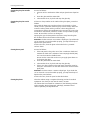
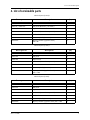
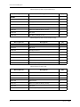
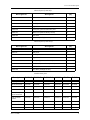
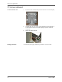
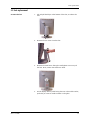
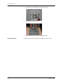
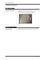
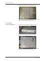
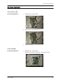
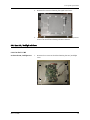
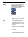
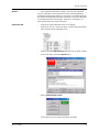
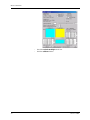
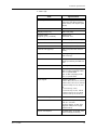
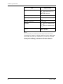
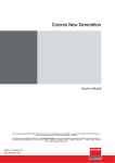
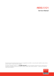
Nio 2-3-5 MP
Service Manual
Supported displays: E-2320 C, E-2320 C SE, E-2320 PA, E-2320 PA S, E-2320, E-3420, E-5420
This technical manual could include technical inaccuracies or typographical errors. BARCO n.v. reserves the right to modify the manual as
often as necessary to keep it as current and accurate as possible.
This manual is copyrighted by BARCO n.v. with all rights reserved. It may not be reproduced, transmitted, stored in a retrieval system, or
translated into any language, any form or by any means - electronic, magnetic, optical, manual or otherwise - in whole or part, without
prior written consent of BARCO n.v.
Orderno B4100444-02
Date November 2007
2
Nio 2-3-5 MP
Table of contents
1. Table of contents
Service precautions 4
Cleaning Instructions 5
List of serviceable parts 7
First level service 11
Front cover replacement 12
Foot replacement 13
Plastic rear cover replacement 15
Firmware: How to check the current version 16
Firmware: Uploading new firmware 17
Advanced service 18
Reading and saving display parameters 19
Writing display parameters in the display 20
LED board replacement 21
Rotary knob replacement 22
Signal board replacement 23
LCD panel replacement 27
BLOS calibration 32
Functional tests 35
Checking factory settings 36
Checking BLOS operation 37
Signature check 38
Visual checks 39
Packaging instructions 40
Troubleshooting 44
Technical specifications 45
Nio 2-3-5 MP
3
Service precautions
2. Service precautions
General
Precautions for assembling the
display
Handling Precautions for the LCD
panel
Caution: Remove the power plug from the mains outlet before
removing any cover
•
Opening the display must be done in a dust-poor environment, to
avoid dust particles on the glass plate or the panel.
•
Opening the display must be done in a dust-poor environment, to
avoid dust particles on the panel.
•
When assembling the display, place all the screws in their holes
without tightening them before they are all in place and the
metallic cover is resting without any mechanical stress on the
panel.
•
Color spots on the display might be observed during operation if
any mechanical stress would be applied to the panel.
•
When assembling the display, be sure to re-apply all the EMC
tapes and other EMC measures. Before applying the tape on metal
parts, degrease the metal using alcohol.
1.
Since the panel surface is easily damaged, pay attention not to
scratch it.
2.
Wipe off water drops immediately. Long contact with water may
cause discoloration or spots.
3.
When the panel surface is soiled, wipe it with absorbent cotton or
any other soft cloth.
4.
Since the panel is made of glass, it may break or crack if dropped
or bumped on hard surface.
5.
Since CMOS LSI is used in the LCD panel, take care of static electricity and ensure human earth when handling.
6.
Do not open nor modify the LCD panel assembly.
7.
When you insert or remove the Signal Interface Connector, be sure
not to rotate nor tilt the Interface Connector of the LCD panel.
8.
After installation of the LCD panel into the display frame, do not
twist nor bend the LCD panel even momentarily. Otherwise the TFT
Module may be damaged.
9.
The Backlight lamp contains mercury. Do not throw it in the trash.
Dispose of it as required by local ordinances or regulations.
10. Do not display the same pattern on the LCD panel for more than
10 hours, to avoid image retention.
4
Nio 2-3-5 MP
Cleaning Instructions
3. Cleaning Instructions
Precautions
The cleaning kit contains:
What else do you need?
•
Caution: Remove the power plug from the mains outlet before
removing any cover
•
Always wear clean protective gloves when handling and cleaning
the display
•
Since the LCD panel and the front glass are easily damaged, pay
attention not to scratch them.
•
Since the LCD panel is easily damaged, pay attention not to scratch
it.
•
Wipe off liquid drops from the LCD panel immediately. Long contact with liquid may cause discoloration or spots.
•
Since the LCD panel is made of glass, it may break or crack if
dropped or bumped on hard surface. Also, do not put any mechanical stress on the LCD panel.
•
3 soft, nonabrasive, dust-free cloths PN° B382816
•
2 pairs of gloves PN° B382818
•
1 touch-up paint bottle for the bezel PNº B1909152
•
1 touch-up paint bottle for the rear plastics PNº B1909151
•
•
•
Neutral glass cleaning product to clean the glass plate.
E.g.: Cleareen, a product of Certified Laboratories.
Prefer products based on alcohol (Ethylalcohol or Isopropylalcohol)
above other neutral glass cleaning products.
Be sure that the product does not contain products of the 'DO NOT
USE' section below.
Solution of 25% Isopropyl Alcohol and 75% de-ionized or distilled
water to clean the LCD panel.
As an alternative for the solution of IPA and water we can recommend “Klear Screen” (TM), a dedicated LCD display cleaner.
A duster or dust remover to blow away dust. E.g.,. DUST OFF 67
(KONTAKT Chemie)
A dust remover is composed of a blend of compressed liquid gases
functioning as propellant. They provide a jet of dry inert gas that
acts like compressed air for a quick and safe removel of dust particles and other dry contaminants on the surface of the lcd panel or
the glass panel.
DO NOT USE:
•
Strong alkalis lye
•
(Lye is a strong caustic alkaline solution of potassium salts,
obtained by leaching wood ashes. It is much used in making soap,
etc.)
Acid
•
Detergents with fluoride
•
Detergents with ammonia
•
Coarse tools:
- Detergents with abrasives
- Steel wool
- Sponge with abrasives
- Steel blades
- Cloth with thread made of steel
Nio 2-3-5 MP
5
Cleaning Instructions
Cleaning the glass plate- Outside
surface
Proceed as follows:
1. Take one of the nonabrasive cloths and put glass cleaner liquid on
it.
2.
Clean the glass with the moist cloth.
3.
Take another clean, dry cloth and wipe the glass dry.
Cleaning the glass plate- Inside
surface
If there are dust particles on the inside of the glass plate, proceed as
follows:
Spray with the duster gas onto the surface to be cleaned. For best
results, use the 'quick shot' method (Spray in short blasts). When the
aerosol is cooling down and the pressure is decreasing (internal
evaporation to restore the equilibrium in the aerosol can), wait a few
moments for the internal pressure to restore and repeat the spraying
action. Do not shake or move can during use.
Spraying the gas, the dust particles are blown away from the glass.
Do not blow them in the direction of the display.
Attention: The dust remover can contains a liquid gas. If you shake the
can or move the can too fast while spraying, you may blow drops of
liquid on the glass surface!
If this is the case, clean the glass as described in the § "Outside
surface" above.
Cleaning the LCD panel
Proceed as follows:
1. If the LCD panel is dirty, take one of the nonabrasive cloths and
moisten the cloth with a solution of 25% Isopropyl Alcohol (IPA)
and 75% de-ionized or distilled water.
2.
Do not use the same cloth as the one you apply glass cleaner to
for cleaning the glass.
Clean the panel with the moist cloth.
3.
Take another clean, dry cloth and wipe the glass dry.
4.
If there are dust particles on the LCD panel, blow them away by
using the dust remover. Do not blow them in the direction of the
glass plate.
Attention: The dust remover contains a liquid gas. If you shake the
can or move the can too fast while spraying, you may blow drops of
liquid on the panel surface!
If this is the case, clean the panel as described above.
Cleaning the plastics
6
Clean the cabinet using a recognized cleaning product for medical
equipment. The cloth you use must be moist, not wet!
The cabinet has been tested for resistance to the following products:
Cidex, Betadine, Alcohol (Isopropyl and Ethyl), Ammonia-based
cleaners (Windex) and Aquasonic Gel.
Nio 2-3-5 MP
List of serviceable parts
4. List of serviceable parts
Electrical parts (E-5420):
Barco part no
Description
Qty
BOARDS :
V322145 / V3221451
LCD panel (BlueBase / ClearBase)
1
K5800262
Signal board
1
K5800271
OSD board (USB and Rotary switch)
1
K5800272
Led board
1
K5800279
Unit BLOS (backlight sensor)
1
KM570057
Display controller (graphics board)
Nio 5 MP
1
Electrical parts (E-3420):
Barco part no
Description
Qty
BOARDS :
V3221372
LCD panel
1
K5800262
Signal board
1
K5800271
OSD board (USB and Rotary switch)
1
K5800272
Led board
1
K5800279
Unit BLOS (backlight sensor)
1
KM570055
Display controller (graphics board)
Nio 2-3 MP
1
Electrical parts (E-2320):
Barco part no
Description
Qty
BOARDS :
V3221613
LCD panel
1
K5800088
Signal board
1
K5800271
OSD board (USB and Rotary switch)
1
K5800287
Led board
1
K5800286
Unit BLOS (backlight sensor)
1
KM570055
Display controller (graphics board) Nio 2-3 MP
1
Nio 2-3-5 MP
7
List of serviceable parts
Electrical parts (E 2320 C up to revision 01):
Barco part no
Description
Qty
BOARDS :
V322301
LCD panel
1
K5800374
Backlight inverters
2
K5800365
Signal board
1
V685050
12V to 18V converter board on Signal board
1
K5800271
OSD board (USB and Rotary switch)
1
K5800272
Led board
1
K5800350
Unit BLOS (backlight sensor)
1
Electrical parts (E 2320 C from revision 02 on):
Barco part no
Description
Qty
BOARDS :
V3223011
LCD panel
1
K5800394
Backlight inverters
2
K5800365
Signal board
1
V685050
12V to 18V converter board on Signal board
1
K5800271
OSD board (USB and Rotary switch)
1
K5800272
Led board
1
K5800350
Unit BLOS (backlight sensor)
1
Electrical parts (E 2320 C SE):
Barco part no
Description
Qty
BOARDS :
8
V322300
LCD panel
1
K5801437
Backlight inverters
2
K5801399
Signal board
1
K5801271
OSD board (USB and Rotary switch)
1
K5801272
Led board
1
K5801350
Unit BLOS (backlight sensor)
1
Nio 2-3-5 MP
List of serviceable parts
Electrical parts (E 2320 PA):
Barco part no
Description
Qty
BOARDS :
V3221613
LCD panel
1
B557302
Backlight inverters
2
K5800097
Signal board
1
K5800096
Transpose (portrait accelerator) unit
1
K5800271
OSD board (USB and Rotary switch)
1
K5800287
Led board
1
K5800294
Unit BLOS (backlight sensor)
1
Electrical parts (E 2320 PA S):
Barco part no
Description
Qty
BOARDS :
V322147
LCD panel
1
B557302
Backlight inverters
2
K5800098
Signal board
1
K5800096
Transpose (portrait accelerator) unit
1
K5800271
OSD board (USB and Rotary switch)
1
K5800287
Led board
1
K5800350
Unit BLOS (backlight sensor)
1
Miscellaneous parts:
Description
E-2320 C
E-2320 PA
E-2320 PAS
E-2320
E-3420
E-5420
Tilt & swivel foot
B410038
B410038
B410038
B410038
B410038
B410038
Front bezel
V6225371
V6223592
V6225372
V6223590
V6224410
V6223640
Rear cover
V622349
V622349
V622349
V622349
V622349
V622349
Cover (door) for
input connectors
V622350
V622350
V622350
V622350
V622350
V622350
Push & Rotate
button
V622352
V622352
V622352
V622352
V622352
V622352
Power cord Euro
Z348791
Z348791
Z348791
Z3487350
Z348791
Z348791
Power cord US
Z348790
Z348790
Z348790
Z348735
Z348790
Z348790
Display:
Accessories:
Nio 2-3-5 MP
9
List of serviceable parts
Description
E-2320 C
E-2320 PA
E-2320 PAS
E-2320
E-3420
E-5420
Power cord China
Z3487500
-
-
Z3487504
Z3487500
Z3487500
Power cord UK
B195613
-
-
External power
supply
B5572297
B5572295
B5572295
B5572296
B557222
B557222
Accessory box
B590312
B590312
B590312
B590312
B590312
B590312
Foam block for
foot
V622416
V622416
V622416
V622416
V622416
V622416
Cardboard buffer
piece
V6046253
V6046253
V6046253
V6046253
V6046253
V6046253
Plastic bag for
display
C592904
C592904
C592904
C592904
C592904
C592904
Left foam buffer
piece
V6223531
V6223531
V6223531
V6223531
V6223531
V6223531
Right foam buffer
piece
V6223541
V6223541
V6223541
V6223541
V6223541
V6223541
Foam buffer
piece for behind
foot
V622411
V622411
V622411
V622411
V622411
V622411
Box for 1 display
V604755
V604755
V604755
V604755
V604755
V604755
Service gloves
B382818
B382818
B382818
B382818
B382818
B382818
Cleaning cloth
31x31 cm
B382816
B382816
B382816
B382816
B382816
B382816
Packing:
Other:
10
Nio 2-3-5 MP
First level service
5. First level service
Nio 2-3-5 MP
11
Front cover replacement
5.1 Front cover replacement
To remove the front cover:
Mounting instructions:
12
1.
Remove the four sunken fixing screws from the rear of the display.
2.
Carefully take the front cover a few centimeter from the display. It
is still connected to the rest of the display by means of the LED
connection.
3.
Unplug the LED connection.
To mount the parts again, follow the procedure in reverse order.
Nio 2-3-5 MP
Foot replacement
5.2 Foot replacement
To remove the foot:
Nio 2-3-5 MP
1.
Lift and pull both clips at the bottom of the foot, to release the
foot.
2.
Remove the rear cover from the foot.
3.
Remove the small screw fixing the small plastic cover on top of
the foot. Next, remove the small cover itself.
4.
Put the display with its panel facing down on a clean table surface,
preferably on a mat to avoid scratches on the glass.
13
Foot replacement
Mounting instructions:
14
5.
Unscrew the 2 screws fixing the round plastic cover.
6.
Lift up the round plastic cover.
7.
Remove the four screws while supporting the foot.
To mount the parts again, follow the procedure in reverse order.
Nio 2-3-5 MP
Plastic rear cover replacement
5.3 Plastic rear cover replacement
To remove the rear cover:
1.
Remove the tilt & swivel foot (see the procedure of the foot
replacement).
2.
Remove the six screws fixing the cover.
3.
Lift up the rear cover.
While lifting the cover, be careful not to damage the rotary knob on
the side of the display.
Mounting instructions:
Nio 2-3-5 MP
To mount the parts again, follow the procedure in reverse order.
15
Firmware: How to check the current version
5.4 Firmware: How to check the current version
To check the firmware version in the
display’s OSD menu:
You can check the current firmware version in the Information menu
inside the OSD main menu.
To check the firmware version with
Mfdcontrol:
1.
Start the program Mfdcontrol.exe.
2.
In the main menu, select the display of which you wish to check
the firmware version.
3.
In the main menu, click on the button General. The General information window appears.
4.
In the General Information window, click on Versions.
5.
In the Versions window, check the version in the Run line. This is
the current firmware version.
16
Nio 2-3-5 MP
Firmware: Uploading new firmware
5.5 Firmware: Uploading new firmware
To upload the firmware:
1.
Start the program Mfdcontrol.exe
2.
In the main menu, select the display of which you wish to check
the firmware version.
3.
In the main menu, click the Upload button
4.
Select "Upload Code" in the dialog box
5.
Select the folder and file with the new HEX code.
6.
7.
Proceed as follows:
Nio 2-3-5 MP
Remark : the hex-code for upload is of a different type than the
hex-code for programming the flash memory on a programmer !
Do not mix up the two or the display will become unusable.
During the upload, a dialog box is displayed with the status. The
display will reboot when the upload is finished.
When finished, a message is displayed. Press OK and Exit to
return to the main menu.
See Section “First level service”.
17
Advanced service
6. Advanced service
18
Nio 2-3-5 MP
Reading and saving display parameters
6.1 Reading and saving display parameters
To read the EDID PROM contents:
To read out the EEPROM data:
About the Nio 2MP EDID PROM
Nio 2-3-5 MP
1.
Start the software tool “Mfdcontrol.exe” (version August 12 2002
at least).
2.
In the main menu, select the proper display.
3.
In the main menu, click on EDID.
4.
Click on Read (EDID PROM) to read the PROM contents.
5.
Click on Save and save the file on the hard disk. As file name you
better use the serial no. of the display. The file extension is .dat.
1.
Start the software tool Mfdcontrol.exe.
2.
In the main menu, select the proper display.
3.
Click on Upload.
4.
In the Upload window, click on EEPROM to file.
5.
The data is saved on the PC as “EExxxxxx”, where xxxxxx is the
display serial number.
For Nio 2MP, it is not necessary to store the EDID-PROM content on PC.
The EDID PROM content is stored within the EEPROM. Each time the
display starts up, the EDID PROM content is loaded from the EEPROM.
19
Writing display parameters in the display
6.2 Writing display parameters in the display
To write the EDID PROM content:
To write the EEPROM data:
20
1.
Start the software tool “Mfdcontrol.exe” (version August 12 2002
at least).
2.
In the main menu, select the proper display.
3.
In the main menu, click on EDID.
4.
Click on Load and locate the proper file.
5.
Click Open to select the file.
6.
Click on Write (EDID PROM) to write the contents in the new EDID
PROM.
1.
Start the software tool Mfdcontrol.exe.
2.
In the main menu, select the proper display.
3.
Click on Upload.
4.
In the Upload window, click on File to EEPROM and locate the
proper file.
5.
Click Open to select the file.
6.
The data is written into the display EEPROM.
Nio 2-3-5 MP
LED board replacement
6.3 LED board replacement
6.3.1 LED board removal
To remove the LED board:
1.
Remove the front cover (see First level service).
2.
Unscrew the LED board.
3.
Replace the LED board.
4.
Put the bezel back in place.
6.3.2 Re-assembling the display
Mounting instructions:
Nio 2-3-5 MP
To mount the parts again, follow the procedure in reverse order.
21
Rotary knob replacement
6.4 Rotary knob replacement
6.4.1 Rotary knob removal
To remove the rotary knob unit:
1.
Remove the foot (see First level service).
2.
Remove the plastic rear cover (see First level service).
3.
Unscrew the 2 screws fixing the rotary knob unit.
4.
Replace the unit.
6.4.2 Re-assembling the display
Mounting instructions:
22
To mount the parts again, follow the procedure in reverse order.
Nio 2-3-5 MP
Signal board replacement
6.5 Signal board replacement
6.5.1 Read and save display parameters
To read the EDID PROM contents:
To read out the EEPROM data:
About the Nio 2MP EDID PROM
1.
Start the software tool “Mfdcontrol.exe” (version August 12 2002
at least).
2.
In the main menu, select the proper display.
3.
In the main menu, click on EDID.
4.
Click on Read (EDID PROM) to read the PROM contents.
5.
Click on Save and save the file on the hard disk. As file name you
better use the serial no. of the display. The file extension is .dat.
1.
Start the software tool Mfdcontrol.exe.
2.
In the main menu, select the proper display.
3.
Click on Upload.
4.
In the Upload window, click on EEPROM to file.
5.
The data is saved on the PC as “EExxxxxx”, where xxxxxx is the
display serial number.
For Nio 2MP, it is not necessary to store the EDID-PROM content on PC.
The EDID PROM content is stored within the EEPROM. Each time the
display starts up, the EDID PROM content is loaded from the EEPROM.
6.5.2 Remove foot
Proceed as follows:
See Section “First level service”.
6.5.3 Remove plastic rear cover
Proceed as follows:
See Section “First level service”.
6.5.4 Remove Signal board Cover
6.5.4.1 For Nio 3 & 5 MP
To remove the Signal board cover:
Nio 2-3-5 MP
1.
Remove the 2 screws and 2 bolts at the input connectors.
23
Signal board replacement
2.
Remove the 13 screws fastening the signal board cover.
3.
Carefully lift the signal board cover and slide it over the input connectors. Be careful not to damage the DVI connector.
1.
Remove the 2 screws and 4 bolts at the input connectors.
2.
Remove the 12 screws fastening the signal board cover.
3.
Carefully lift the signal board cover and slide it over the input connectors. Be careful not to damage the DVI connector.
6.5.4.2 For Nio 2MP
To remove the Signal board cover:
24
Nio 2-3-5 MP
Signal board replacement
6.5.5 Remove Signal board
6.5.5.1 For Nio 3 & 5 MP
To remove the Signal board:
1.
Disconnect the 9 signal cables.
2.
Remove the 6 screws fastening the board.
3.
Remove the board.
1.
Disconnect the 7 signal cables.
Remark: one cable is screwed with a clamp to the board.
6.5.5.2 For Nio 2MP
To remove the Signal board:
Nio 2-3-5 MP
25
Signal board replacement
2.
Remove the 11 screws fastening the board.
3.
Remove the board.
6.5.6 Re-assemble the display
Mounting instructions:
To mount the parts again, follow the procedure in reverse order.
6.5.7 Write display parameters in the display
To write the EDID PROM content:
To write the EEPROM data:
About the Nio 2MP EDID PROM
26
1.
Start the software tool “Mfdcontrol.exe” (version August 12 2002
at least).
2.
In the main menu, select the proper display.
3.
In the main menu, click on EDID.
4.
Click on Load and locate the proper file.
5.
Click Open to select the file.
6.
Click on Write (EDID PROM) to write the contents in the new EDID
PROM.
1.
Start the software tool Mfdcontrol.exe.
2.
In the main menu, select the proper display.
3.
Click on Upload.
4.
In the Upload window, click on File to EEPROM and locate the
proper file.
5.
Click Open to select the file.
6.
The data is written into the display EEPROM.
For Nio 2MP, it is not necessary to store the EDID-PROM content on PC.
The EDID PROM content is stored within the EEPROM. Each time the
display starts up, the EDID PROM content is loaded from the EEPROM.
Nio 2-3-5 MP
LCD panel replacement
6.6 LCD panel replacement
6.6.1 Read and save display parameters
To read the EDID PROM contents:
To read out the EEPROM data:
About the Nio 2MP EDID PROM
1.
Start the software tool “Mfdcontrol.exe” (version August 12 2002
at least).
2.
In the main menu, select the proper display.
3.
In the main menu, click on EDID.
4.
Click on Read (EDID PROM) to read the PROM contents.
5.
Click on Save and save the file on the hard disk. As file name you
better use the serial no. of the display. The file extension is .dat.
1.
Start the software tool Mfdcontrol.exe.
2.
In the main menu, select the proper display.
3.
Click on Upload.
4.
In the Upload window, click on EEPROM to file.
5.
The data is saved on the PC as “EExxxxxx”, where xxxxxx is the
display serial number.
For Nio 2MP, it is not necessary to store the EDID-PROM content on PC.
The EDID PROM content is stored within the EEPROM. Each time the
display starts up, the EDID PROM content is loaded from the EEPROM.
6.6.2 Remove front cover
Proceed as follows:
See Section “First level service”.
6.6.3 Remove foot
6.6.4 Remove plastic rear cover
Proceed as follows:
Nio 2-3-5 MP
See Section “First level service”.
27
LCD panel replacement
6.6.5 Remove Signal board Cover
6.6.5.1 For Nio 3 & 5 MP
To remove the Signal board cover:
1.
Remove the 2 screws and 2 bolts at the input connectors.
2.
Remove the 13 screws fastening the signal board cover.
3.
Carefully lift the signal board cover and slide it over the input connectors. Be careful not to damage the DVI connector.
1.
Remove the 2 screws and 4 bolts at the input connectors.
6.6.5.2 For Nio 2MP
To remove the Signal board cover:
28
Nio 2-3-5 MP
LCD panel replacement
2.
Remove the 12 screws fastening the signal board cover.
3.
Carefully lift the signal board cover and slide it over the input connectors. Be careful not to damage the DVI connector.
6.6.6 Open LCD / Backlight unit Cover
6.6.6.1 For Nio 3 & 5 MP
To release the LCD / Backlight cover:
Nio 2-3-5 MP
1.
Remove the 4 screws at the sides fastening the LCD / Backlight
cover.
29
LCD panel replacement
6.6.6.2 For Nio 2MP
To release the LCD / Backlight cover:
1.
Remove the 6 screws at the sides fastening the LCD / Backlight
cover.
6.6.7 Remove LCD / Backlight unit
6.6.7.1 For Nio 3 & 5 MP
To remove the LCD / Backlight
assembly:
1.
Carefully lift the LCD / Backlight cover.
2.
Now turn the cover like opening the cover of a box.
3.
Disconnect the cables from the backlight inverter and driver
boards.
4.
Remove the LCD / Backlight assembly.
1.
Carefully lift the LCD / Backlight cover while guiding the cables
through the opening.
2.
Now turn the cover like opening the cover of a box.
6.6.7.2 For Nio 2MP
To remove the LCD / Backlight
assembly:
Note: The E-2320 C SE has a different way of opening than the
other 2MP displays:
30
Nio 2-3-5 MP
LCD panel replacement
E-2320 C SE: Open from the short side
Other 2MP displays: Open from long side
3.
Disconnect the cables from the backlight inverter and driver
boards. Also remove the clamps fastening the cables.
4.
Remove the LCD / Backlight assembly.
6.6.8 Re-assemble the display
Mounting instructions:
To mount the parts again, follow the procedure in reverse order.
6.6.9 After replacing the LCD/Backlight unit
After replacing the LCD / Backlight
unit, proceed as follows:
Nio 2-3-5 MP
•
It is necessary to calibrate the BLOS after replacing the LCD / Backlight unit. See chapter “BLOS calibration”.
31
BLOS calibration
6.7 BLOS calibration
Introduction
The calibration must be performed using the Minolta CA 110 / 210
measurement instrument, the calibration cover and the BARCO
software tool Mfdcontrol.exe (IMPORTANT- internal use only).
You must use the metal calibration cover because it is the only way to
ensure that the lens of the Minolta is in the correct position and at the
right distance of the panel.
The calibration is best performed in a darkened room.
Calibration set-up
Warm-up times
Perform the CA- 110 / 210 0calibration
•
The Minolta must be warmed up for at least 15 min. before 0-calibration of the CA- 110 / 210 will be started (is needed to have the
accuracy of 2% when you measure luminance values less then 5
cd/m²).
•
The display must be warmed up for at least 2 hours without power
interruption.
For CA-110:
• Be sure the measuring probe is connected to the CA-110.
•
Power-on the CA-110.
•
Put the measuring/viewing selector in the viewing position (the
black spot on the knob must correspond with the white spot on
the measurement head).
•
•
In this position an image can be seen in the viewfinder, no light
will reach the sensor. The metal calibration cover must not be used
to darken the probe.
Press the 0-cal button on the CA-110.
Put the viewing selector back to the measuring position (no image
can be seen in the viewfinder). The 2 white spots corresponds in
the measuring position.
For CA-210:
• Be sure the measuring probe is connected to the CA-210.
32
•
Power-on the CA-210.
•
Turn the pointing ring to the “0-CAL” position.
•
Do not point the probe in the direction of high luminance. Be sure
the pointing ring is set to “0-CAL” and not to “POINTER”.
•
Press the “0-cal” button on the CA-210.
•
After 0-calibration, turn the pointing ring to the “MEAS” position.
Nio 2-3-5 MP
BLOS calibration
Remarks:
•
If the ambient temperature changes, redo the zero calibration
The zero calibration can be checked in normal working position by
putting the measurement head on a flat surface, so no light will reach
the sensor and the display will show 0.00 cd/m². If the zero calibration
is not well performed, the message “offset error” will appear or a
value greater then zero will be measured.
Calibrate the BLOS
Nio 2-3-5 MP
•
Connect the metal calibration cover to the display.
•
Connect the CA 110 / 210 to the PC by a proper cable (see illustration) and put it in the calibration cover.
•
Start the program Mfdcontrol.exe (version Sept. 29 2003 at least).
•
In the main menu, click the I-Guard button
•
Click on Monochrome I-Guard
•
In the next menu, the program will detect the BLOS.
33
BLOS calibration
34
•
Check the Include Backlight check box.
•
Click the Calibrate button
Nio 2-3-5 MP
Functional tests
7. Functional tests
Nio 2-3-5 MP
35
Checking factory settings
7.1 Checking factory settings
To check the factory settings:
1.
Start the program Mfdcontrol.exe.
2.
In the main menu, select the display of which you wish to check
the settings.
3.
In the main menu, click on the button General.
4.
The General information window appears
In the General information window, check the following items:
5.
6.
36
- Is the display serial number correct?
- Is the display stock number correct?
- Is the display type correct?
- Option DPMS must be checked.
- Option Stabilizer must be checked.
- Option Power LED must not be checked.
In the Backlight section at the bottom of the window, there is a
slider. Move the slider between minimum and maximum. The
backlight of the panel should change between minimum and
maximum. As another consequence, the Stabilizer option is deselected again.
Select the Stabilizer option again. The luminance value next to
the slider should go to the calibrated value (see Technical Specifications) again.
Nio 2-3-5 MP
Checking BLOS operation
7.2 Checking BLOS operation
To check the BLOS operation:
Nio 2-3-5 MP
1.
Run the tool Mfdcontrol.exe (Version Sept. 29 2003 at least).
2.
In the main menu, click on I-Guard.
3.
In the I-Guard Calibration window, select Monochrome I-Guard.
4.
In the Built in Sensor window, read out the Internal Device value.
This should be an acceptable value (see the technical specs - Luminance).
37
Signature check
7.3 Signature check
Introduction:
This test should be performed after replacing an Interface Board. The
Signature Check tests a part of the Video circuit on the Interface Board.
To perform the Signature check:
1.
Run the software tool Signature test.exe
2.
In the menu, select the head and click on the button Measure. The
signature check is running now, displaying a number of test patterns.
3.
After completion, the software returns if there were errors or not.
If there were errors, check the file Signature.log in the root directory of the software tool.
How to judge the information from
the log file
The Signature test actually consists of 2 signature checks. Signature 1 is
calculated at the input of the FPGA on the Signal board. Signature 2 is
calculated at the outputs of the FPGA.
So, the knowledge of which of the signature checks is faulty can give
an indication of where the problem resides.
• If Signature 1 and Signature 2 are both faulty, there is a problem
that can reside on the imaging board in the PC, a problem with the
video cable, or a problem with the display’s Signal board. So, first
figure out if the imaging board or video cable is not faulty.
•
38
In case Signature 1 should be OK, but Signature 2 is faulty, the
problem resides on the Signal board.
Nio 2-3-5 MP
Visual checks
7.4 Visual checks
Perform the following visual checks:
Nio 2-3-5 MP
•
No scratches on the panel surface or plastics?
•
No dust particles between the panel and the glass?
•
When you disconnect the signal cable, does the display go into
stand-by? (power LED turns orange)
•
Check the display quality by displaying some test patterns. A number of useful test patterns are bundled in the software tool Grayscale.exe.
39
Packaging instructions
8. Packaging instructions
Introduction
This procedure describes how to pack the display from the service
department to another location, e.g., to an MIS service hub.
To perform this procedure, be sure to use the original parts from the
packaging of the display.
To pack the display properly:
1.
Take the empty accessory box.
2.
If necessary, put the power and signal cables in a plastic bag. Put
the cables in the largest compartment of the accessory box.
3.
Remove the rear cover of the display foot. Wrap it in protective
foam.
Leaving the cover on the foot could result in damage to the cover.
4.
40
Put the wrapped foot cover on the cables in the largest compartment of the accessory box.
Nio 2-3-5 MP
Packaging instructions
5.
If necessary, wrap the power adapter in a plastic bag. Put the
adapter in the smallest compartment in the accessory box.
6.
Be sure the connector cover is mounted on the display.
7.
Push the display in the lowest position.
In case of a new type of foot, block its height positioning system
by means of the red fixation pin.
8.
Put a foam block between the cable guidance wings on the foot.
Fix the foam block by means of adhesive tape.
9.
Pull a plastic bag over the display.
10. Turn the display 90 degrees and put it in the proper foam buffer
piece.
Nio 2-3-5 MP
41
Packaging instructions
Attention: The buffer pieces are not identical.
11. Put the other buffer piece on the other side of the display.
12. Open the cardboard box and turn it 90 degrees.
13. Push a cardboard buffer piece in the cut-away in the foam buffers
at the front side of the display.
14. Slide the display into the cardboard box, with its foot going first.
Cardboard buffer
15. Put the box upright.
16. Put the T-shaped foam buffer piece behind the display in the box.
Push it down behind the display foot to fix the foot during transport.
17. Put the accessory box inside the box at the rear of the display.
There are cut-outs in the foam buffer pieces for the accessory box.
42
Nio 2-3-5 MP
Packaging instructions
18. Close the box and tape it.
Nio 2-3-5 MP
43
Troubleshooting
9. Troubleshooting
Sometimes if there is a problem, it is not obvious what is the origin of
the problem: The Interface board or the LCD panel.
There is a relatively easy way to test where lies the cause of the
problem. Therefore, replace the interface board by a spare board. This
is no problem if you do not perform a calibration.
If the problem persists after replacing the board, the cause is the LCD
panel. If the problem is solved after replacing the board, the cause is
the board.
44
Nio 2-3-5 MP
Technical specifications
10. Technical specifications
E-3420:
Item
Nio 2-3-5 MP
Specification
Picture panel
20.8-inch TFT AM-LCD IPS dual domain
Resolution
Native: 2048 x 1536
Display area (H x V)
423.9 x 318 (mm)
Viewing angle
(@ 10/1 contrast)
Vertical: 170º
Horizontal: 170º
Pixel Pitch
0.207 mm (H) x 0.207 mm (V)
Native color resolution
8 bits / sub-pixel
Luminance
500 cd/m² (calibrated)
Contrast ratio
600/1 (on/off in dark environment)
Response time
25 ms typical (@ 25° C after 30 min
warm-up)
Controls
Push / turn control wheel for stand-by
switching and OSD controls
Input connectors
DVI dual channel
Signal systems
DVI Digital
Video: Complying to DVI Rev 1.0 specifications
Sync: Complying to DVI Rev 1.0 specifications
USB standard supported
USB 1.1
Power source
Input for 12 VDC power supply unit: 90 ~
264 VAC
Input for display: 12 VDC. (The supplied
12VDC power supply must be used)
Power consumption
79 watts (max., at 90 VAC, maximum
backlight, USB load)
Dimensions (W x H x D)
In perpendicular vertical position, highest position, tilt = 0°, swivel = 0°:
229 x 358 x 143 mm
Net weight
13 kg
Operating Temperature
0°C to 40°C, 15°C to 35°C within specs
Storage Temperature
-20°C to 60°C
Humidity
8% - 80% (non-condensing) for operation
5% - 95% (non-condensing) for storage
45
Technical specifications
E-5420:
Item
46
Specification
Picture panel
20.1-inch Advanded-SFT
Resolution
Native: 2560 x 2048
Display area (H x V)
399.36 x 319.49 (mm)
Viewing angle
(@ 10/1 contrast)
Vertical: 85º
Horizontal: 85º
Pixel Pitch
0.156 mm (H) x 0.156 mm (V)
Native color resolution
8 bits / sub-pixel
Luminance
500 cd/m² (calibrated)
Contrast ratio
600/1 (on/off in dark environment)
Response time
30 ms typical (@ 25° C after 30 min
warm-up)
Controls
Push / turn control wheel for stand-by
switching and OSD controls
Input connectors
DVI dual channel
Signal systems
DVI Digital
Video: Complying to DVI Rev 1.0 specifications
Sync: Complying to DVI Rev 1.0 specifications
USB standard supported
USB 1.1
Power source
Input for 12 VDC power supply unit: 90 ~
264 VAC
Input for display: 12 VDC. (The supplied
12VDC power supply must be used)
Power consumption
80 watts (max., at 90 VAC, maximum
backlight, USB load)
Dimensions (W x H x D)
In perpendicular vertical position, highest position, tilt = 0°, swivel = 0°:
382 x 589 x 212 mm
Net weight
11.1 kg
Operating Temperature
0°C to 40°C, 15°C to 35°C within specs
Storage Temperature
-20°C to 60°C
Humidity
8% - 80% (non-condensing) for operation
5% - 95% (non-condensing) for storage
Nio 2-3-5 MP
Technical specifications
E- 2320 C (SE):
Item
Nio 2-3-5 MP
Specification
Picture panel
20.1-inch diagonal viewable
screen TFT (thin film transistor)
active matrix, color liquid crystal
display
Resolution
Native: 1600 x 1200
Display area (H x V)
408 x 306 (mm)
Viewing angle
(typical, @ 10/1 contrast)
Vertical: 176º
Horizontal: 176º
Pixel Pitch
0.255 mm (H) x 0.255 mm (V)
Native color resolution
24 bit color
Luminance
180 cd/m² (calibrated)
Contrast ratio (typical)
900/1 (on/off in dark environment)
Response time
8 ms typical (@ 25° C after 30
min warm-up)
Controls
Push / turn control wheel for
stand-by switching and OSD controls
Input connectors
DVI single link, D-Sub15 pin
Signal systems
DVI Digital, RGB Analog
Video on DVI: Complying to DVI
Rev 1.0 specifications
Sync on DVI: Complying to DVI
Rev 1.0 specifications
Input signals
Possible resolutions:
• 640 x 480 @ 60, 75, 85, 100 Hz
• 800 x 600 @ 60, 75, 85, 100 Hz
• 1024 x 768 @ 60, 75, 85, 100
Hz
• 1152 x 864 @ 75 Hz
• 1152 x 870 @ 60, 85, 100 Hz
• 1280 x 1024 @ 60, 75, 85 Hz
• 1600 x 1200 @ 59, 60 Hz (*)
USB standard supported
USB 1.1
Power source
Input for 12 VDC power supply
unit: 90 ~ 264 VAC
Input for display: 12 VDC. (The
supplied 12VDC power supply
must be used)
Power consumption
64 watts (max., at 90 VAC, maximum backlight, USB load)
47
Technical specifications
Item
Specification
Dimensions (W x H x D)
In perpendicular vertical position, highest position, tilt = 0°,
swivel = 0°:
385 x 585 x 250 mm
Net weight
12 kg
Operating Temperature
0°C to 40°C, 15°C to 35°C within
specs
Storage Temperature
-20°C to 60°C
Humidity
8% - 80% (non-condensing) for
operation
5% - 95% (non-condensing) for
storage
Altitude
7500 m storage
3000 m operation
Notice:
Due to our policy of continuous product improvement, the above
specifications are subject to change without prior notice. BARCO shall
not be liable for technical or editorial errors or omissions contained
herein; nor for incidental or consequential damages whatsoever
resulting from furnishing, performance or use of this material.
48
Nio 2-3-5 MP
Technical specifications
Nio 2-3-5 MP
49