1
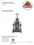
AirBossTM Evolution, AirBossTM Evolution Plus and ProAirTM Evolution Compressed Air Respiratory Protection Equipment Approvals TM TM Instructions for Use Open the cylinder valve slowly, but fully to pressurise the system, recheck the pressure gauge and proceed. TM AirBoss Evolution, AirBoss Evolution Plus and ProAir Evolution are positive pressure, open circuit, self contained compressed air respiratory equipment certified by NIOSH/MSHA. TM TM Use TM AirBoss Evolution, AirBoss Evolution Plus and ProAir Evolution must only be used in conjunction with compressed air cylinders approved by NIOSH/MSHA. For Your Safety TM TM Take gauge reading regularly. Whistle will sound at whistle warning unit pressure setting. Proceed to safe area, at least when whistle sounds, by shortest and safest route. TM AirBoss Evolution, AirBoss Evolution Plus and ProAir Evolution approved equipment incorporates Dräger pre-set, and sealed pressure reducer and balanced piston unit assemblies. Drägers’ guarantee is void should original seal caps be tampered with, removed, or broken. Correct operational condition is only valid if Dräger service, and re-seals pressure reducer and balanced piston unit. Use of this equipment requires wearer training, knowledge, observance of these User’s Instructions, and compliance with National Regulations, Laws and Standards, governing the use of respiratory equipment in the country of use. Use equipment only for the purpose specified in this manual, or as confirmed in writing by Dräger. Guidelines for proper use of equipment should be consistent with NFPA 1500 - standard on Fire Department Occupational Safety and Health Program. Trained personnel should inspect and service equipment at regular intervals and a record kept of such inspections and servicing. Dräger recommends a service contract be obtained from your Dräger Branch or Agent. Contact Dräger for details of Service Contracts and Service Training Courses. Use only original Dräger Spare Parts for service and maintenance. Notify Dräger in the event of component fault or failure. Use only Dräger Test Equipment for service and maintenance. Warranty and Liability Statement TM TM Terms and Conditions of warranty, for the AirBoss Evolution, AirBoss TM ProAir Evolution, can be obtained from Dräger on request. 11 6 1146 0017 Safety Notes: a. Additional Air Required If momentary additional airflow is required, press ‘red’ bypass button of lung demand valve. In the unlikely condition of low or blocked airflow, or if required to maintain additional airflow, press and rotate the ‘red’ bypass button to ‘lock’ the flow setting (80 - 130Litres/min). Duration of the air supply is reduced while the bypass is in operation. When set in this condition the wearer must evacuate to a safe area. If it is suspected that the apparatus is blocked then an investigation by a trained authorised person must be carried out before re-using the apparatus. Evolution Plus and Responsibility for reliable function of equipment transfers to the owner or operator when serviced, or repaired by untrained personnel, (not employed or authorised by Dräger) or when used in a manner not conforming to its intended use. Description Researched and designed to meet the TM specific needs of the end user, the AirBoss TM Evolution, AirBoss Evolution Plus and TM ProAir Evolution variants utilise the same high performance first stage pressure reducer, lung demand valve, carbon composite backplate and are fully compatible with a wide range of compressed air cylinders and facepieces. The above variants can be fitted with either a Mechanical Gauge, Flashing Gauge or Sentinel. Details of equipment variants and approved accessories are available from Dräger on request. Intended Use TM TM AirBoss Evolution, AirBoss Evolution TM Plus and ProAir Evolution positive pressure two stage compressed air respiratory protection equipment, used in approved cylinder, facepiece and demand valve combinations, provide the wearer with respiratory protection when working in a contaminated, or oxygen deficient gaseous atmosphere. Effective working duration of equipment is dependant on capacity (volume) of cylinder selected and breathing rate of wearer. Technical Data High Pressure Connection 2216 psi connection to CGA 346 4500 psi connection to CGA 347 Lung Demand Valve to Facepiece Connection Push-In - Positive Pressure with By-pass Pressure and Flow - Equipment Medium Pressure: 87 psi to 130 psig Air Flow: in excess of 1000 litres/minute. at 290 psig in excess of 500 litres/minute. Pressure and Flow - Airline Supply If equipment fitted to independent air supply, the following parameters should be noted: Air Supply Pressure: 90psig to 120psig Airline Hose Length: 5 feet to 300 feet Note: maximum working length of hose Must Not be made up of more than 12 individual hose lengths. Safety Note: Air quality Must conform to the minimum grade requirements for Type 1 Gaseous air as defined in Compressed Gas Association Commodity Specification for Air, G-71 (Grade D or higher quality). Use of airline connection by a second person, Buddy Breather, voids NIOSH approval. Whistle Setting (Flashing Gauge) Whistle setting for the following pressure units is as follows: 2216 psi Unit - setting 510 psig to 600 psig 4500 psi Unit - setting 1035 psig to 1215 psig The activation setting of the LED’s of the Flashing Gauge (if fitted) is also within the above setting parameters. WeightsTM TM AirBoss Evolution, AirBoss Evolution TM Plus and ProAir Evolution Self Contained Breathing Equipment (without cylinder) 8.5lbs. Charged Compressed Air Cylinders 4500psi/60 minutes (Carbon composite) 19.0lbs 4500psi/60 minutes (Kevlar composite) 22.0lbs 4500psi/60 minutes (Fibreglass composite) 26.5lbs 4500psi/45 minutes (Carbon composite) 14.8lbs 4500psi/45 minutes (Kevlar composite) 17.0lbs 2 7 0156 0016 4500psi/45 minutes (Fibreglass composite) 20.6lbs 4500psi/30 minutes (Carbon composite) 11.4lbs 4500psi/30 minutes (Kevlar composite) 12.4lbs 4500psi/30 minutes (Fibreglass composite) 13.2lbs 2216psi/30 minutes (Carbon composite) 12.0lbs 2216psi/30 minutes (Fibreglass composite) 13.9lbs 2216psi/30 minutes (Hoop Wrap, Fibreglass) 16.3lbs 2216psi/30 minutes (Full Aluminium) 21.4lbs 3 2 1 Equipment Dimensions Data indicated is less cylinder and with carrying harness folded in stowage condition. Length: approx. 24.5 inches Width: approx. 12.5 inches Height: approx. 6 inches Important Note: The activation setting of the LED’s of the Flashing Gauge (if fitted) is also within the whistle setting parameters. Audible and visual signals/warnings may however not activate at exactly the same time. The LED’s of the Flashing Gauge will switch off before the audible warning. 8 3 0018 0157 1 ProAirTM Evolution b. Excessive or Loss of Airflow In the unlikely condition of high or loss of airflow, close the cylinder valve then immediately begin to slowly re-open the valve, using it as an adjusting valve to set sufficient airflow to cover the maximum inhalation requirement. This action must only be carried out in an emergency situation to escape to a safe area. An investigation by a trained authorised person must be carried out before re-using the apparatus. Note: On SCBA having cylinders fitted with a locking (ratchet) valve, adjustment of the cylinder valve while wearing the SCBA must be performed as follows. Reach behind with the left hand to support the backplate and at the same time with the right hand, push and hold in the valve handwheel, rotating the handwheel clockwise to close the valve then immediately begin to slowly re-open the valve, using it as an adjustment valve to set sufficient airflow to cover the maximum inhalation requirement. Release the valve handwheel when the required airflow is achieved. Preparation for use Connecting to Independent Air Supply If Flashing Gauge fitted – fit new batteries as follows: Note: Ensure independent air supply source meets pressure and air quality requirements as defined in Technical Data section of this User’s Instruction. Flashing Gauge - Fitting Batteries Fold back rubber cover from the gauge to access the battery cover. Refer to Fig. 1. Using TORXTM - TX 8 unscrew the four captive screws and carefully remove the battery cover taking care not to damage the sealing gasket. Insert two new batteries into the battery compartment ensuring correct positioning of terminals. Check that sealing gasket is not damaged. Relocate battery cover and secure using the four captive screws. Do Not overtighten (max. 0.4Nm). Reposition rubber cover over the gauge. 2 AirBoss Evolution TM Press reset (1 Fig. 9) mechanism of the lung demand valve to switch ‘Off’ positive pressure. Open the cylinder valve slowly, but fully, to pressurise system. Note: If an immediate leak is indicated from the demand valve - press the centre of the rubber cover to release the positive pressure mechanism - press reset mechanism to switch ‘Off’ positive pressure. Repeat the action two or three times to eliminate the leak. If leak not eliminated return balanced piston unit to Dräger Service. Close the cylinder valve and observe the pressure gauge. Gauge reading shall not decrease more than 200psig in 1 minute. Whistle Warning Unit Test Cover the outlet of the demand with ball of the hand, press the centre of the rubber cover, turning ‘On’ positive pressure. Slowly vent system by carefully lifting the ball of the hand maintaining a slow decrease in pressure. Observe the gauge. Whistle should sound at the preset pressure. Note: Whistle pre-set by Dräger to the following values: 2216 psi Unit - 510psig to 600psig 4500 psi Unit - 1035psig to 1215psig Should whistle not sound at the required pressure, refer to Service Manual. 4 6 9 4 0584 Pull down shoulder adjusting straps (Fig. 5) until equipment is secure and comfortable. Do Not overtighten. Tuck strap ends under waistbelt. Extend facepiece head harness straps, leaving centre strap in position, (Fig. 7). Put neck strap over neck, insert neck strap stud into hole in centre strap of head harness. Carry out High Pressure Leak Test. Check valve port and the reducer handwheel threads are undamaged, connector O ring is in position, and undamaged. Place the backplate horizontal, extend the cylinder strap, slide cylinder through strap locating the valve port to the reducer handwheel. Lift unit upright, screw the handwheel into the valve port, (handtight). Do Not use tools. Place backplate horizontal, take up slack on cylinder strap (Fig. 2) pull strap over cylinder to activate Camlock (Fig. 3) secure strap to Velcro. High Pressure Leak Test 5 0020a/0163 Fitting Cylinder Pre Operational Checks 3 Turn ‘On’ the independent air supply then connect air supply hose to the coupling of the Buddy Breather connection. Close equipment cylinder valve and breathe normally from the independent air supply. Note: Cylinder pressure must not be less than 80% full. If pressure is below maximum charging pressure of the cylinder, this will reduce available duration to the wearer. 5 0153 Important Note: The activation setting of the LED’s of the Flashing Gauge (if fitted) is also within the above setting parameters. Audible and visual signals/warnings may however not activate at exactly the same time. The LED’s of the Flashing Gauge will switch off before the audible warning at the following approximate values, 2216 psi Unit – below 200psig 4500 psi Unit - below 400psig Following satisfactory whistle test, press reset mechanism to switch ‘Off’ positive pressure. Connecting Demand Valve to Facepiece Check that the facepiece port and the demand valve O ring are clean and undamaged. Push the demand valve into the facepiece port until it clicks into position. A slight turning motion of the LDV during pushing will aid connection. Check that the attachment is secure. Pull the demand valve away from facepiece - there should be no axial movement. Operation Putting on equipment Extend the waistbelt and shoulder adjusting straps. Put on equipment taking weight on shoulders by pulling on shoulder adjusting straps. Do Not tighten. Fasten waistbelt buckle. Pull ends of waistbelt adjusting straps (see Fig. 4) until waistbelt pad is secure and comfortable on hip. Tuck strap ends between body and waistbelt pad. Press the reset mechanism of the demand valve to switch ‘Off’ the positive pressure. Open the cylinder valve slowly, but fully, to pressurise the system. Check the gauge. IN AN EMERGENCY - If independent air supply ‘Fails’, proceed as follows: Open cylinder valve slowly but fully. Breathe normally. Disconnect air supply hose from Buddy Breather connection. If necessary leave hazardous area by shortest and safest escape route. Safety Warning: Do Not remove equipment until in safe area, clear of hazard. Release the side straps of the head harness, press the reset mechanism of the demand valve to switch ‘Off’ the positive pressure then remove the facepiece. Close the cylinder valve. Unbuckle the waistbelt, lift shoulder strap buckles to loosen, remove the equipment. Putting on Facepiece Safety Warning: Beards, side whiskers, facial stubble and/or spectacle frames will interfere with face seal of facepiece, and adversely affect protection of the wearer. Press centre of the rubber cover of the demand valve to vent system. Following venting press the reset mechanism of the demand valve to switch ‘Off’ positive pressure. Detach the neck strap stud from the centre strap of the head harness. Spread the harness, (Fig. 7) then place chin into the facepiece, position harness over the head locating the harness centre plate with the back of the head. Tighten both the lower, then the upper straps evenly towards back of the head. Fig. 8. Tuck in strap ends. On achieving a face seal the positive pressure demand valves will automatically activate on first breath inhalation. Breathe normally then prior to use perform function checks. Note: If the by-pass has been set in constant flow position, turn the ‘red’ button to unlock, and switch ‘Off’ the by-pass. Inhale and hold breath. Unit must balance, i.e. no audible leak. Continue breathing. Expired air should easily flow out of the exhalation valve. Press the ‘red’ by-pass button of the demand valve checking that an additional airflow is delivered into the facepiece. Close the cylinder valve. Breathe normally to vent the system. When the gauge indicates zero, hold breath. Facepiece should hold onto the face indicating a positive seal. Note: If a leak detected, open the cylinder valve, readjust the head harness and retest. 2216 psig Units 50 mg/cubic meter (4.99 x 10⁻⁵ ounce/ cubic feet. 4500 psig Units 35 mg/cubic meter (3.49 x 10⁻⁵ ounce/ cubic feet. Safety Warning: If moisture content exceeds recommended levels, ice particles can form reducing, or blocking air flow. Water content of breathing air must be checked. Recharge to the indicated pressure stamped on the neck, or shoulder of the cylinder. Visual Inspection Check integrity of: Carrying plate. All straps, buckles and harness. Valves, connectors and cylinder supports. Facepiece. Flashing Gauge – if fitted Replace batteries annually regardless, or when the brilliance of the LED’s is significantly reduced. Note: Use only approved batteries. Refer to the specifications detailed on the label of the gauge battery cover. Cleaning, Disinfecting, Drying Carefully clean, disinfect, and thoroughly dry contaminated dirty components as necessary. Use suitable baths for containing cleaning and disinfecting solutions. Immerse and manually agitate components in solutions. Dräger recommends that no form of mechanical, electrical or ultrasonic agitation be used. Safety Note: Refer to manufacturers’ usage instructions when using cleaning and disinfecting agents. It is important that attention be paid to concentration and reaction times. Do Not use organic solvents, such as Acetone, Alcohol, White Spirit, Trichloroethylene or similar. Dräger recommends the following: Cleaning Dräger Safety Wash. Do Not exceed a temperature of 86 degrees Fahrenheit. Disinfecting Incidur. Do Not exceed a temperature of 86 degrees Fahrenheit. Details of cleaning and disinfecting agents are available from Dräger on request. Rinsing and Drying Remove cleaning and disinfecting solutions by rinsing in clean water, followed by drying. Do Not exceed a temperature of 140 degrees Fahrenheit when drying components. Lung Demand Valves It is important to follow these instructions to internally clean and disinfect the lung demand valve. Refer to Fig. 9. After Use Note: Do Not drop or throw down equipment as damage could occur. Function Checks To prevent ingress of moisture into the cylinder, ensure that the cylinder valve remains ‘closed’ until connected to the charging unit. Dräger recommends that the moisture content in charged cylinder should not exceed the following: Pass equipment to the Service Department. Routine Maintenance To be performed after Use. See also Maintenance and Test Intervals Chart. Removal of cylinder Safety Warning: Cylinder valve should be closed and system vented. Lift free end of the cylinder strap against the Camlock to release, loosen the strap. Unscrew handwheel from cylinder valve. Slide cylinder away from reducer, remove from equipment. Recharge the cylinder. Charging Cylinders Safety Warning: Air quality for compressed air cylinders must conform to the minimum grade requirements for Type 1 gaseous air as defined in the Compressed Gas Association Commodity Specification for Air, G-7.1 (Grade D or higher quality). Fold the rubber cover (2) from the front of the demand valve body. Grip the bayonet cap (3), turn anticlockwise and remove the bayonet cap. Note: The positive pressure spring remains attached to the bayonet cap. Do Not remove, stretch or compress the spring. Take care not to damage the spring during cleaning and disinfecting procedures. Using the thumb and forefinger carefully grip centre plate of the diaphragm (4) then tilt the centre plate and lift the diaphragm from the body of the demand valve. Remove the slip ring (5). Note: The diaphragm must not be ultrasonically cleaned as this will affect the bonded area of the diaphragm. Clean and disinfect manually. Fold rubber cover back over the front of the demand valve body to protect the lever (6) of the balanced piston. Immerse, and manually agitate the demand valve, diaphragm, slip ring, and bayonet cap in cleaning fluid. (Refer to cleaning fluid instructions.) After cleaning, rinse components in clean water. Immerse and manually agitate components in disinfecting fluid. (Refer to disinfecting fluid instructions.) After disinfection fold the rubber cover from the front of the demand valve and rinse components in clean water. Take care not to damage the lever (6) of the balanced piston. Connect the hose of the demand valve to a medium pressure air supply. Press reset (1) then turn ‘ON’ the air supply. Gently press lever (6) blowing out fluid residue. Safety Note: Wear suitable eye protection. Disconnect from air supply, dry the components and, if necessary remove the excess fluid. After drying, carefully locate the outer bead of diaphragm into groove in the demand valve body. 3339135: 16th Edition : November 2009 : Subject to Modification - (A3-D-P) AirBossTM Evolution, AirBossTM Evolution Plus and ProAirTM Evolution Compressed Air Respiratory Protection Equipment Carefully locate tapered side of the slip ring into the recess in the bead of the diaphragm. Locate the spring of the bayonet cap into the centre of the diaphragm and refit bayonet cap. Fold the rubber cover back over the front of the demand valve. Press reset (1) to switch ‘Off’ positive pressure. Connect the demand valve to the equipment and perform Pre Operational Checks as detailed in the Instructions for Use for the equipment. Pressure Reducer and Hose Assemblies Unfasten the hose loops, releasing the hoses, and remove the reducer and hose assembly. Fold the rubber cover (2) from the front of the demand valve body. Grip the bayonet cap (3), turn anticlockwise and remove the bayonet cap. Note: Do Not immerse the pressure reducer in cleaning or disinfecting solutions. For cleaning and disinfecting, remove pressure reducer and hose assembly from the backplate. Remove the locknut, bolt and washers from the reducer mounting. Fold the rubber cover back over the front of the demand valve. Press reset (1) to switch ‘Off’ positive pressure. Connect the demand valve to the equipment and perform Pre Operational Checks as detailed in the Instructions for Use for the equipment. Note: The positive pressure spring remains attached to the bayonet cap. Do Not remove, stretch or compress the spring. Take care not to damage the spring during cleaning and disinfecting procedures. Using clean cloth, moistened in cleaning, or disinfecting solution, remove dirt and contaminants from the pneumatic assembly. Using clean cloth moistened in clean water remove disinfecting residue followed by drying. Storage - Ready for Use Fully extend shoulder straps, waistbelt and head harness of facepiece. Store equipment ‘ready for use’ in a cool dry environment, free from dust and dirt. Protect rubber parts from direct sunlight. Using thumb and forefinger carefully grip centre plate of diaphragm (4) then tilt the centre plate and lift diaphragm from the body of the demand valve. Remove slip ring (5). Discard diaphragm. Carefully locate the outer bead of the new diaphragm into groove in the demand valve body. Carefully locate tapered side of the slip ring into the recess in the bead of the diaphragm. Locate the spring of the bayonet cap into the centre of the diaphragm and refit bayonet cap. Note: Do Not exceed a temperature of 140 degrees Fahrenheit when drying components. Re-assemble reducer and hose assembly to backplate and harness. Note: Refer to For Your Safety. Instructions for Use Replacing Diaphragm See Maintenance and Test Intervals Chart. Refer to Fig. 9. Safety Note: Ensure equipment secured and supported by cylinder, and not backplate, when stored ‘ready for use’, on wall or bulkhead mounting, e.g. Fire Tender. Note: Refer to approved user instruction manual for complete list of sub-assembly component parts that make up approved assembly. FAULT, CAUSE, REMEDY Airline respirators can be used only when the respirators are supplied with respirable breathing air meeting the requirements of CGA G-71. Grade D or higher quality. Use only the pressure ranges and hose lengths specified in the user instructions. Contains electrical parts that have not been evaluated as an ignition source in flammable or explosive atmospheres by MSHA/NIOSH. Failure to maintain this product could result in injury or death. All approved respirators shall be selected, fitted, used and maintained in accordance with MSHA, OSHA and other applicable regulations. Never substitute, modify, add or omit parts. Use only exact replacement parts in configuration as specified by manufacturer. Refer to users instructions and/or maintenance manuals for information on the use and maintenance of these respirators. Special or critical users instructions and/or specific use limitations apply. Refer to instruction manual before donning. S - Special or Critical Users Instructions Approved for use at temperatures above minus 25 degrees Fahrenheit (minus 31.7 degrees Centigrade). When used as a Combination Self Contained breathing Apparatus, not more than 20 per cent of the air supply can be used during entry. During supplied air use, the cylinder valve must remain closed. If the supplied air fails, open the cylinder valve and immediately proceed to fresh air. Safety Warning: When equipment is fitted with Integrated Pass Unit - Do Not assemble equipment with 60 Minute (4500psig) Fibreglass composite cylinder, as NIOSH approved weight limit will be exceeded. MAINTENANCE AND TEST INTERVALS FAULT CAUSE Facepiece leakage (Leak test with equipment in position) Cautions and Limitations Carry out Inspection, Testing and Servicing of Equipment in accordance with this table. Record all data in Equipment Log Book. These instructions also apply to non-used (in Storage) Equipment. REMEDY 1. Faulty or missing sealing ring or O ring at demand valve connection 2. Exhalation valve leaking 3. Speech diaphragm defective 4. Headstraps not tight Fit or replace sealing ring or O ring Unsatisfactory communication Speech diaphragm defective Replace High pressure leak 1. Check tightness of connections 2. Check hose seals on hose connections Tighten as required Replace seals as required Safety relief valve venting Pressure reducer defective Return pressure reducer to Dräger Service Demand valve venting (constant flow) 1. Banjo O rings worn 2. Balanced piston leaking 3. Diaphragm incorrectly fitted 4. By-pass knob engaged Replace Return balanced piston unit to Dräger Service Re-assemble correctly Turn 'Off' By-pass Whistle not sounding correctly Whistle dirty Clean and re-test Whistle sounding continuously 1. Damaged sealing on H.P. capillary 2. Defective activation mechanism Replace sealing and re-test Return pressure reducer to Dräger Service Description Clean and re-assemble or replace Replace Tighten Complete Equipment After Use m Functional and Leak Testing as defined in Instructions for Use Flow and Static Tests per Manufacturer's instructions m Medium Pressure Check m Sintered Filter m m Replace H.P. Connector O-ring Cylinder Every Year nm Visual Inspection Pressure Reducer Every Month m Charge to correct pressure m Charged Pressure Check. Check Test Date Stamped on Cylinder Cylinder Pressure Test (According to National Standards). Re-Certification Cylinder Valve Basic Overhaul as necessary or at time of Cylinder Re-Certification. Dräger Recommendation Grease Demand Valve connector O-ring (Molykote 111) as required. tESTING eQUIPMENT Equipment should be tested as stated in the relevant User’s Instructions, with test equipment listed below, and/or by reference to appropriate Service/ Training Manual. Test Equipment Refer to Dräger Service Manual Contact Dräger for details of Service Contracts and Service Training Courses. DRAEGER PROAIR EVOLUTION AND AIRBOSS EVOLUTION (NFPA1981:1997) SERIES DRAEGER SAFETY INC PITTSBURGH, PENNSYLVANIA, USA 1-800-922-5518 DRAEGER SAFETY UK LIMITED BLYTH, NORTHUMBERLAND, ENGLAND +44 (0)1670 352891 DRAEGER CANADA LTD MISSISSAUGA, ONTARIO, CANADA (905) 821 8988 Draeger AirBoss Evolution Series and ProAir Evolution Series Open-Circuit, Pressure-Demand, Entry & Escape Self-Contained Breathing Apparatus or Combination Open-Circuit, Pressure-Demand, Entry & Escape Self-Contained Breathing Apparatus & Type "C" Supplied-Air Respirator. These respirators are approved only in the following configurations Respirator Components TC - 1 Alternate Facepieces Alt. LDV Alt. Hrnss Assy. Alternate Pneumatic Assys. Alternate Airline Connectors Alternate Cylinder and Valve Assemblies Alternate Airline Hose Assemblies (feet) Cautions & 2 Limitations Accessories R50092 R51350 R52972 R53070 4052609 4052719 4052955 R54450 R54694 R54696 R54697 R54699 4056621 4053038 4053039 4053040 R55080 3339401 3338712 3352571 3337850 3337851 3337791 3351264 3351499 3350607 3350608 3350609 3350610 3352609 3352610 3352611 3352612 3337827 3337829 3337846 3337848 3337792 3337794 3350467 3350468 3351564 3351565 3351350 3351349 4050189 4054747 4050180 4054748 4052015 3337060 4053267 4052004 4052238 4054841 3338040 3338041 3338042 3338043 4055964 3337890 3337650 3350946 3350947 3350948 4059357 4059357L 4059061 4059061L 4059062 4059062L 4054854 4054854L 4059063 4059063L 3336106 3339633 4053437 4054916 4054930 4057102 4054931 4054963 4054964 4055001 4056197 4056200 4055002 4055025 4055026 4055027 4055028 R51548 R53325 3337700 3337701 3337852 3337853 3337777 3351021 3339626 3337548 3337012 3339280 3337549 3351027 3338801 3350822 4056029 4056030 4055963 4056623 4056348 4056624 4056566 3350339 4056750 4056751 3354328 3335845 AIRLINE HOSE 5-24FT AIRLINE HOSE 5-24FT AIRLINE HOSE 25FT AIRLINE HOSE 25FT AIRLINE HOSE 50FT AIRLINE HOSE 50FT AIRLINE HOSE 75FT AIRLINE HOSE 75FT AIRLINE HOSE 100FT AIRLINE HOSE 100FT GAUGE LIGHT LDV HOLDER WELDING SHIELD WELDING SHIELD HAIRNET, PANORAMA NOVA NFPA HAIRNET, PANORAMA NOVA NFPA HAIRNET, PANORAMA NOVA HAIRNET, FUTURA NFPA HAIRNET, FUTURA VOICE AMPLIFIER VOICE AMPLIFIER RADIO INTERFACE RADIO INTERFACE RADIO INTERFACE RADIO INTERFACE RADIO INTERFACE RADIO INTERFACE SPECTACLE KIT PANORAMA NOVA SPECTACLE KIT FUTURA RAPID FILL FACILITY RAPID FILL FACILITY QUICK CONNECT QUICK CONNECT WAIST BELT WAIST BELT HOSE LOOP WAIST BELT LOOP CHEST STRAP CHEST STRAP ADJUSTING BELT ASSY (METAL) ADJUSTING BELT ASSY (METAL) SENTINEL ASSEMBLY SENTINEL ASSEMBLY SUPER I-PASS II SHOULDER SUPER I-PASS II WAIST METAL CYLINDER STRAP CYLINDER STRAP WITH ID NUMBER AIRLINE CONNECTOR HOSE POUCH HOSE LOOP WITH HOOK RUBBER HANDWHEEL COVER ALTERNATE WHISTLE ASSEMBLY SHOULDER SHEATH ( PSS100 ) SHOULDER SHEATH ( PSS100 ) US TELEMETRY PORTABLE UNIT ASSY PANORAMA NOVA MASK FRONT PORT SECURING CAP Protection 13F-377 SA / SC / PD 30 MIN 2216 PSIG X X X X X X X X X X X X X X X X X X X X X X X X X X X X X X X X X X X X X X X X X X X X X X X X X X X X X X X X X X X X 13F-378 SA / SC / PD 30 MIN 4500 PSIG X X X X X X X X X X X X X X X X X X X X X X X X X X X X X X X X X X X X X 13F-379 SA / SC / PD 45 MIN 4500 PSIG X X X X X X X X X X X X X X X X X X X X X X X X X X X X X X X X X X X X X X X X X X X X X X X X X X X X X X X X X X X X X X X X X X X X X X 13F-380 SA / SC / PD 60 MIN 4500 PSIG X X X X X X X X X X X X X X X X X X X X X X X X X X X X X X X X X X X X X X X X X X X X X DEIJ MNOS X X X X X X X X X X X X X X X X X X X X X X X X X X X X X X X X X X X X X X X X X X X X X X X X X X X X X X X X X X DEIJ MNOS X X X X X X X X X X X X X X X X X X X X X X X X X X X X X X X X X X X X X X X X X X X X X X X X X X X X X X X X X X X DEIJ MNOS X X X X X X X X X X X X X X X X X X X X X X X X X X X X X X X X X X X X X X X X X X X X X X X X X X X X X X X X X X DEIJ MNOS 1. PROTECTION SA - Supplied-Air SC - Self-Contained PD - Pressure-Demand 2 - CAUTIONS AND LIMITATIONS D - Air-line respirators can be used only when the respirators are supplied with respirable air meeting the requirements of CGA G-7.1, Grade D or higher quality. E - Use only the pressure ranges and hose lengths specified in the User's Instructions. I - Contains electrical parts that may cause an ignition in flammable or explosive atmospheres. J - Failure to properly use and maintain this product could result in injury or death. M - All approved respirators shall be selected, fitted, used, and maintained in accordance with MSHA, OSHA, and other applicable regulations. N - Never substitute, modify, add, or omit parts. Use only exact replacement parts in the configuration as specified by the manufacturer. O - Refer to User's Instructions and/or maintenance manuals for information on use and maintenance of these respirators. S - Special or critical User's Instructions and/or specific use limitations apply. Refer to User's Instructions before donning. Dräger, while endeavouring to ensure correctness of statements of fact and advice contained in this publication; gives no guarantee or warranty in respect thereof, and accepts no liability for any mis-statement or inaccuracy in publication, or for any omission therefrom. Draeger Safety, Inc. 101 Technology Drive Pittsburgh PA 15275 Phone: 800-922-5518 Fax: 800-922-5519 http://www.draeger.com Draeger Canada Ltd. Mississauga, Ontario, Canada (905) 821-8988 Dräger Safety UK Limited Ullswater Close Riverside Business Park Blyth Northumberland NE24 4RG Tel: +44 1670 352891 Fax: +44 1670 356266 3339135: 16th Edition : November 2009 : Subject to Modification - (A3-D-P) ProAir and AirBoss 97 certified configurations.xls