1
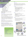
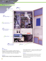
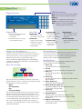
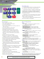
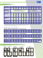
Another Innovation From Dual-Lite S p e c t r o n ® Continuous Power Compatibility Confidence lsn L i f e S a f e t y N e t w o r k Central Inverter System S p e c t r o n ® lsn L i f e S a f e t y N e t w o r k The Life Safety Network The Spectron LSN Life Safety Network is designed to provide: ● ● ● ● ● ● ● ● ● ● A simplified system approach to emergency lighting and power “ No break” power P ulse width modulated technology 1 00% load compatibility M aximized reliability R educed maintenance expense E nhanced security Improved building aesthetics M inimized space requirements C ommunications capability Most importantly, it delivers optimum safety for building occupants. Advanced Design The basic elements of an inverter system are batteries, an inverter, a charger and a transformer. Spectron LSN, however, is unlike traditional IPS, FT or UPS systems because of its innovative design. This pulse width modulated (PWM) high-frequency inverter utilizes the latest IGBT (Insulated Gate Bipolar Transistor) technology. The AC-in to AC-out operating efficiency is 98%, well above other central inverter system equipment. This outstanding efficiency translates to lower operating costs. Communications All Spectron LSN inverter systems are equipped with an RS232 communication interface designed to give the user greater flexibility in monitoring and controlling the system. Plus... Compatibility Spectron LSN systems provide 100% compatibility with all connected loads. “No break” sinusoidal output assures that even voltage-sensitive or frequency-sensitive loads will operate normally during emergency operation. Simplicity ● ● ● ● ● ● S ingle, centrally located power source Intelligent, easy-to-use interface panel A utomatic, programmable self-diagnostic operation U tilizes existing lighting fixtures for emergency illumination No secondary backup power or lighting equipment required C onnects into existing electrical panel — no special wiring required Safety ● ● ● ● ● A udio-visual service alarms M eets or exceeds all UL 924 and UL 1778 requirements D igitally generated sine wave output 4 2,000 RMS symmetrical ampere short-circuit rating B uilt-in backfeed relay to protect personnel from potential shock hazard Security ● ● ● S pectron LSN systems are normally installed in utility areas away from normal public access L ocking cabinetry prevents tampering Password-protected user interface prevents operation by unauthorized personnel Communications Big Performance...Small Footprint Spectron LSN inverter system’s feature-rich design is provided in an incredibly compact package. Spectron LSN system capacities under 5KVA require less than four square feet of floor space; all other systems up to 17.5KVA require less than eight square feet — the smallest footprints in the industry! Lighting Security The Spectron LSN Advantage... • Compatibility • Simplicity • Safety • Security It all adds up to confidence. 1 Support Functions Egress System Fire Protection Building Management New York City BEC Calendar No. 43323 Spectron LSN - A Major Advance In Life Safety PWM Technology Pulse width modulated (PWM) inverter control is designed to produce the output wave form by switching battery current at a high-frequency rate. The primary circuit of the inverter is made up of four Insulated Gate Bipolar Transistors (IGBT). IGBTs provide the multiple benefits of compactness, high efficiency, low maintenance and long equipment life, as well as maximum adaptability and control. The four IGBTs are sequenced on and off at a 16,000 Hz rate. Because of the inverter’s high-frequency switching response time, many compatibility problems with loads such as power factor-corrected ballasts, HID lighting and microprocessorcontrolled equipment are eliminated. Interruption-Free Power Spectron LSN provides continuous power to all critical life safety loads and other secondary support systems. This “no break” switching between utility and inverter power means that all connected equipment will continue to operate normally under emergency conditions. Voltage Regulation Spectron LSN’s Boost Tap Regulation protects your loads from “brownouts” and recurrent low-voltage transients by sensing any drop in voltage and “boosting” the voltage back up to nominal without drawing from the batteries and shortening their lives. Mixed Loads Spectron LSN’s “no break” design provides continuous operation to mixed loads. Capacitive, inductive or resistive loads will operate normally, as will voltage-sensitive or frequency-sensitive equipment. PWM design results in: igher efficiency, lower operating cost H Smaller, lighter, more compact design ● Quieter operation ● Improved load compatibility ● ● Self-Testing/Self-Diagnostic Operation Auto-Testing And Reporting Self-testing/self-diagnostic electronics perform continuous testing of subsystems, insuring performance to prescribed operating parameters. User-programmable discharge tests are automatically performed on a weekly, monthly and annual basis. Date, time and duration of these tests can be programmed to meet state, local authority and individual requirements. All testing events are automatically logged in memory and can be displayed on the user interface panel. Reduced Maintenance With the Spectron LSN system, a single inverter unit in a centralized location greatly simplifies maintenance, testing and service. With its standard self-testing/self-diagnostic feature, most routine testing is accomplished automatically without the need for manual intervention. In the event of system operation outside designed parameters, alarm functions automatically indicate and identify the component requiring service. Greater Reliability Tested to stringent NFPA 101 and NEC 700 requirements, Spectron LSN is listed to UL 924 and UL 1778 standards. Spectron LSN design technology meets “real world” performance demands and self-diagnostic operation means years of trouble-free, reliable operation. Alarms And Meters Spectron LSN features audible and visual alarms with automatic logging in memory of the 25 most recent alarm events. The conditions monitored include (but are not limited to): Charger failures Output overload warning ● High/low AC output voltage ● High/low output frequency ● High, low or near low battery voltage Ambient temperature Battery cabinet temperature ● Heatsink temperature ● Transformer temperature ● Temperature probe failure ● Internal communication failure ● System test failure ● ● ● ● Digital metering of system parameters and operating readings provide assurance of system readiness. Input AC volts Nominal AC frequency ● Output AC volts ● Output AC frequency ● Output AC amps ● Output watts ● Output volts-amps ● Load percentage ● Power factor ● Ambient temperature attery cabinet temperature B Heatsink temperature ● Transformer temperature ● Battery volts ● Battery amps ● Approximate runtime remaining ● Time/date ● System hours ● Inverter minutes ● ● ● ● 2 S p e c t r o n ® lsn L i f e S a f e t y N e t w o r k Design Excellence Inverter Control Board DC Input AC Input/Output Input EMI/RFI Filter Input and Battery Circuit Breakers Control Panel Optional Output Circuit Breakers Air Filters Plus... Cost Efficiency When all factors are considered, including equipment, installation, operating and maintenance costs, Spectron LSN becomes the clear choice to minimize a facility’s total expense for providing life safety power and lighting. Aesthetics Traditional solutions for life safety egress lighting include unit equipment on walls or ceilings. This approach detracts from 3 interior design aesthetics. Spectron LSN supplies power to existing lighting fixtures, eliminating the need for special emergency lighting fixtures. Security Centrally located in a utility area, Spectron LSN is secure and safe. Locked cabinetry and a password-protected control panel prevent tampering or system operation by unauthorized personnel. Control Panel LED Status Indicators Display Functions AC-On - AC power is present at output terminals Ready - Unit is ready for emergency operation Emergency Power - Unit is operating on battery power Charging - Unit battery is being charged Alarm - Operation outside of pre-programmed operating parameters detected Display Readout Control Keys Clear Key (CLR) Clears the last entered character and cancels or resumes scrolling display feature ● Large, easy-to-read characters ●2 -line x 40-character LCD display ●P rovides continuous scrolling of 20 metered functions Enter Key (ENT) Allows users to enter commands to the system Intuitive, User-Friendly Design Located on the inverter cabinet’s front door, the user interface panel allows the user to monitor and control the Spectron LSN system. The microprocessor-controlled display includes an array of LED indicator lights, a 2-line x 40-character digital display and a coded keypad to display over 250 system parameters, operating modes, alarms and stored logs. Menu-Driven Display Main Menu Meters User Programming Logs Factory Programming The Spectron LSN user interface provides a menu-driven display that allows access to all system information through the following four primary sub-menus: • Meters • User Programming • Logs • Factory Programming The menu-driven display provides users with a structured, intuitive method of accessing system information. The display is a user-friendly interface that eliminates the need for confusing manuals while allowing easy access to all system programming, operating parameters, meters and logs. The interface design also allows the selection of “Hot Keys” as an alternate means of accessing frequently requested information. Program Key (PRG) Allows authorized users to change system programming with the use of “Hot Keys” Previous Key (PRV) Returns the display to the previous menu screen Display Key (DSP) Allows users to use “Hot Keys” to display system parameters Main Menu Key (MAN) Returns the display to the main menu Password Protection To ensure that only authorized personnel operate the unit, every Spectron LSN system is password protected. No control functions can be accessed or operating parameter changes made without password authentication. Stored Test results The following system logs and reports are held in system memory and can be viewed at any time: 1 Service Log Logs password levels entered and FAX status 2 Test Log Logs start times and pass/fail status of all system tests 3 Alarm Log Logs last 40 system alarms, their time of activation and duration 4 Inverter Log Logs last 20 inverter events, including turn on/turn off times and run duration 5 Battery Voltage Log Logs battery system voltage hourly 6 Battery Discharge Voltage Log Logs battery voltage and system output VA every five minutes while in inverter mode 7 Power Log Continuously logs system power levels 8 Peak Value Report Maintains peak system parameter readings for input voltage, output voltage, output current, battery voltage and output VA 9 Diagnostic Status Report Continuously monitors and logs internal microprocessor communication status 4 S p e c t r o n ® lsn L i f e S a f e t y N e t w o r k System Features and Design System Operations AC Utility Input Solid-State Transfer Switch Energy Storage Transformer Filter Control Circuits and Utility Switch Microprocessor Pulse Width Modulated Inverter Battery Charger • A solid-state charger transforms the incoming utility voltage into a regulated DC supply voltage to charge the batteries. AC Emergency Power Battery System Features ● ● ● ● ● ● ● ● ● ● ● ● ● ● ● ● ● ● ● ● ● ● ● ● 5 True “no break” power to loads Pulse width modulated sine wave output Low input current distortion Unique “Off-Line” design increases efficiency to 98% and reduces heat output Up to 150% momentary overload capacity Surge and transient protection circuitry 42,000 RMS symmetrical ampere short-circuit rating Inverter load versatility — lighting (including fluorescent, incandescent, HID, electronic or power-factor corrected ballasts), fire, security, communication systems and other critical loads Provides computer and network backup M icroprocessor control allows completely automatic self-diagnostic operation to warn of potential problems Password protected to prevent unauthorized tampering Automatic self-testing and test logging as required by NFPA 101 Automatic logging of alarm and inverter events 2-line x 40-character digital display Inverter communication — intelligent, two-way communication capability provided through the system’s RS232 terminal B uilt-in backfeed relay to protect personnel from potential shock hazard S tandard 90-minute battery runtime (optional runtimes available) L oad flexibility and reliability — use of a building’s existing lighting elements for emergency reduces the likelihood of unknown lamp failure N o additional backup systems to maintain or test Intelligent, easy-to-use system D isplay panel monitors and controls all parameters Two-year, on-site electronics warranty covers parts and labor Batteries carry pro-rata warranty O nly front access required for service • A maintenance-free battery is provided on standard models to maintain power to the inverter. The batteries are fitted with a suitably rated DC switch and fuse to provide overload and short-circuit protection and also allow isolation from the system for maintenance purposes. • A high-frequency, pulse width modulated inverter transforms the battery energy into low-distortion, no break, sine wave AC voltage to supply the emergency load. • 90% boost tap for line regulation protects against brownouts and conserves batteries for emergencies. Electrical Specifications Input Input voltage: 120, 208, 240, 277, or 347 VAC +10-15%. Other voltages available on request ● Input frequency: 60Hz ±3% ● Synchronizing slew rate: 1 Hz per second nominal ● Operating temperature: 0°C to 40°C (32°F to 104°F) ● Input lightning protection: Meets ANSI 62.41, UL 924 and UL 1778 requirements ● Output Output voltage: 120, 240, 277, 120/240, 120/277, or 347 VAC. Other voltages available upon request ● Output regulation: (static) ±5% based on a 5% - 100% resistive load ● Output distortion: Less than 5% THD linear load ● Load power factor: .75 lag to .8 lead ● Output frequency: Normally, synchronized to utility, +.05 Hz during emergency ● Overload: 150% momentary. 120% for five minutes ● T ime to transfer to inverter after utility power failure: No break ● Battery Battery charger: Automatic with internal diagnostic indicators Recharge time: 24 hours. Meets UL 924 requirements ● Battery protection: Automatic low-battery voltage disconnect. Automatic restart upon utility return ● Battery switch: Also used as battery isolator ● Standard battery: S - Sealed lead-calcium 10-year life ● Optional batteries: G - Sealed lead-calcium 20-year life N - Wet nickel-cadmium 25-year life ● Battery voltage: 96VDC or 144VDC (system dependent) ● Runtimes: 90 minutes standard. Other runtimes available on request ● Relative humidity: 95% non-condensing ● ● Note: 100% battery capacity rated at 25°C (77°F). Optimum system performance between 20°C (68°F) and 29°C (85°F); temperatures outside of this range will affect battery performance and life. IMPORTANT: Features and specifications are subject to change without notice. Contact factory for most recent product information. Unit Specifications KVA/KW Rating 1.0K Power Factor Rating 2.0K 2.7K 3.7K 4.8K 5.5K 6.6K 8.3K 10.0K 12.5K 15.0K 17.5K .8 lead to .8 lead to .8 lead to .8 lead to .8 lead to .8 lead to .8 lead to .8 lead to .8 lead to .8 lead to .8 lead to .8 lead to .75 lag .75 lag .75 lag .75 lag .75 lag .75 lag .75 lag .75 lag .75 lag .75 lag .75 lag .75 lag Input/Output Voltage Combinations Available — Single Phase Input VAC: 120, 208, 240, 277, 347 Output VAC: 120, 240, 277, 347, 120/240(1), 120/277 Other voltages available; consult factory (2) AC Input Voltage/ Input Circuit Breaker Rating 120/20A 208/15A 240/15A 277/15A 347/15A 120/30A 208/20A 240/15A 277/15A 347/15A 120/70A 208/40A 240/35A 277/30A 347/25A 120/70A 208/40A 240/35A 277/30A 347/25A 120/80A 208/50A 240/45A 277/40A 347/30A — 208/70A 240/60A 277/50A 347/50A — 208/80A 240/70A 277/60A 347/50A Output Voltage and Maximum Output Current In Amperes 120/8.3 120/16.6 120/22.5 120/30.8 120/40.0 240/4.2 240/8.3 240/11.3 240/15.4 240/20.0 277/3.6 277/7.2 277/9.7 277/13.4 277/17.3 347/2.9 347/5.8 347/7.8 347/10.7 347/13.4 120/45.8 240/22.9 277/19.9 347/15.9 120/55.0 240/27.5 277/23.8 347/19.0 120/69.1 240/34.6 277/29.9 347/23.9 120/83.3 120/104.1 120/125 240/41.7 240/52.1 240/62.5 277/36.1 277/45.1 277/54.2 347/28.8 347/36.0 347/43.2 10 10 10 Standard Charger Size (amps) 5 120/40A 208/25A 240/20A 277/20A 347/20A 5 120/50A 208/30A 240/25A 277/25A 347/20A 5 5 10 Input VAC: 208, 240, 277, 347 (3) Output VAC: 120, 240, 277, 347, 120/240(1), 120/277 Other voltages available; consult factory (2) 10 — — 208/100A208/125A — 240/80A 240/100A — 277/70A 277/90A 277/100A 347/60A 347/80A 347/80A 15 15 120/146 240/72.9 277/63.2 347/50.4 15 System DC Voltage 96 96 96 96 96 96 96 144 144 144 144 144 Heat Output (BTU/Hr.) 175 350 473 648 840 963 1,155 1,453 1,750 2,188 2,625 3,063 (1)On systems with 120/240VAC output, loading may not exceed 50% of the system's total KVA rating on any 120V leg. Loading beyond 50% on any 120V leg will cause an unsafe condition and transformer failure will occur. Call our Service Line at 800-848-6439 for alternate load connection configurations. (2) An external transformer may be required with certain input/output voltage configurations. Consult factory for details. (3) Input voltage on 17.5KVA model limited to 277 and 347VAC only. Standard Battery Systems for 90-Minute Runtime Type S Battery – Maintenance-Free Sealed Lead-Calcium – 10-Year Design Life Expectancy System Capacity System Configuration Total Weight (lbs.) * 1.0K A 838 2.0K A 1,116 2.7K A 1,122 3.7K A 1,222 4.8K A 1,492 5.5K B 1,926 6.6K B 2,130 8.3K B 2,475 10.0K B 2,829 12.5K B 2,861 15.0K C 4,121 17.5K C 4,393 5.5K B 2,062 6.6K B 2,630 8.3K B 2,679 10.0K B 3,589 12.5K C 3,657 15.0K D 4,885 17.5K D 5,491 5.5K C 2,532 6.6K C 2,812 8.3K D 3,481 10.0K D 3,940 12.5K E 4,720 15.0K E 5,505 17.5K Consult Factory Type G Battery – Maintenance-Free Sealed Lead-Calcium – 20-Year Design Life Expectancy System Capacity System Configuration Total Weight (lbs.) * 1.0K A 1,365 2.0K A 1,384 2.7K A 1,390 3.7K A 1,472 4.8K B 1,684 Type N Battery – Wet-Cell Nickel-Cadmium – 25-Year Design Life Expectancy 1.0K B 1,075 Systems Capacity System Configuration Total Weight (lbs.) * 2.0K B 1,486 2.7K B 1,644 3.7K B 1,894 4.8K B 2,232 * Approximate system weights Cabinet Configurations (90-Minute Runtime) Configuration “A” Configuration “C” Configuration “B” Configuration “E” Configuration “D” Depth 18 5/8" 92'' 92'' 92'' 46'' 30'' 60'' 60'' 90'' 90'' 6 S p e c t r o n ® lsn L i f e S a f e t y N e t w o r k Options Batteries Note: Batteries for all Spectron LSN inverter systems are shipped separately. Batteries must be installed and energized within 90 days of shipment or warranty is void. Spectron LSN’s batteries provide sufficient power to maintain the output voltage of the inverter for a minimum of 90 minutes. All batteries are enclosed in lockable cabinets. Adequate space is provided to ensure easy routine maintenance. Standard Batteries Sealed Lead-Calcium — Type S Spectron LSN’s standard lead-calcium battery is completely sealed and requires no addition of water over its life expectancy. It is constructed with a polypropylene case and cover, which include UL-recognized, low-pressure safety release vents. No gassing will occur in normal use. The elements utilize calcium grid alloy, and the electrolyte is trapped in absorbent glass mat (AGM) separators. Designed life expectancy is 10 years at 77°F/25°C. Long Life Sealed Lead-Calcium — Type G This optional battery is completely sealed and requires no addition of water over its life expectancy. Quick inspection and installation are possible because the electrical connections are located at the front of the battery. The battery case and lid are constructed of flame retardant ABS material. The plates are separated by a highly porous fiberglass mat, which functions as the electrolyte retainer and provides the highest possible oxygen recombination efficiency. Type G batteries have a life expectancy of 20 years at 80°F/27°C. Longest Life, Wet-Cell Nickel-Cadmium — Type N This optional battery is maintainable and requires the addition of distilled water over its life expectancy. The nickel-cadmium battery provides operation over the widest range of temperatures, from 0°C/32°F to 60°C/140°F. Translucent polypropylene containers are standard. Each cell is provided with a flip-top, flame-arresting, UL-recognized vent cap. Interior cell construction consists of pocket plate nickel-cadmium elements in an alkaline electrolyte. Covers are supplied to provide dead-top isolation. Type N batteries have a 25-year life expectancy at 77°F/25°C. 7 Options Communication Options Fax Modem Option (FAX) The Computer Fax Modem is an option that automatically notifies the user of system test results and alarm conditions. This is accomplished by sending a detailed fax to up to six preprogrammed phone numbers. Fax Modem can establish communication via RS232 to perform any system function. The Fax Modem Option is comprised of a single board computer with factory-installed software, modem card and associated cables. The Fax Modem Option allows for remote monitoring via modem connection, notification of alarm conditions by fax to technical support and five additional fax machines, and faxed reports of all UL 924-required system tests of the system. Entire system is factory installed. ●R equires customer supplied dedicated analog phone line ●F ax machine phone numbers can be programmed locally using the unit keypad or computer terminal or remotely via modem. Numbers can also be programmed at time of installation The facsimile-modem automatically sends a fax to the numbers programmed whenever: ● The unit performs a monthly or annual system test ● The unit sounds an alarm Remote Status Panel (RSP) The Remote Status Panel provides remote annunciation for the Spectron LSN to indicate inverter and alarm status. The remote status panel is supplied in a 4-inch x 53/4-inch electrical box. It consists of five LEDs and an alarm beeper. Criteria for installation: ● Must be installed within 1,000 feet of the Spectron LSN ●S even-conductor-minimum, 22AWG wire for connection from options board to Remote Status panel must be supplied by installer System Monitoring Terminals (SMT) The SMT option provides three functional terminal blocks: ● Connection points for Inverter and Alarm relays. Low power contacts change status with either inverter or alarm events. ● Connection points for a Remote Status Panel to allow the addition of an RSP at any time. ● Connection points for an Emergency Power Off (EPO) switch to allow for safe remote shut-down of system regardless of operating mode. Alternate Runtime (AR) Runtimes other than the standard 90 minutes may be specified. When ordering alternate runtimes, specify discharge time required in minutes. Example: AR30 Short Battery Cabinet (SBC) For applications where headroom is limited, the Short Battery Cabinet (SBC) can be used to reduce the overall installation height by 15 inches. The Short Battery Cabinet is available on systems with ratings from 1.0kVA to 6.6kVA. Dimensions are 31” H x 30” W x 18 5/8” D. Circuit Breaker Options Output Circuit Breakers with Alarms A maximum of 14 positions (20 positions without alarms) are available for all models. Single pole, 120VAC and 277VAC breakers occupy one position each. Double pole 240VAC breakers occupy two positions each. See page 10 for ordering information. Normally-Off Output Circuit Breakers Used when connected loads are to be energized only during emergency inverter operation. Normally-off circuit breakers are user programmable for a delay of up to 999 seconds. Single pole, 120VAC and 277VAC breakers occupy one position each. Double pole 240VAC breakers occupy two positions each. See page 10 for ordering information. Internal Bypass Switch (IBS) The Internal Bypass Switch is a threeposition “make before break” service switch mounted inside the cabinet. The IBS is compatible with all input/output combinations and works with any combination or quantity of output circuit breakers. Accessories Multiplexer (MX) The multiplexer is an external device that enables a single phone line to communicate with up to 16 Spectron LSN units via their built-in RS232 communication ports. This is accomplished by installing a phone line and FAX option in only one of the systems to be monitored. Systems can be installed up to 100 feet away from the Master without the use of Short Haul Modems. The use of a Multiplexer reduces the number of phone lines needed for remote communications, dramatically reducing the cost. Communications with the Multiplexer are identical to those of a Fax Modem. Short Haul Modem (SHM) Short Haul Modems are devices that boost signal levels when RS232 communications are installed more than 100 feet away from Spectron LSN. One device is installed next to the Spectron LSN and the other is installed next to the computer communicating with Spectron LSN. Maintenance Bypass Switches The Maintenance Bypass Switch is a device that enables power to be removed from the inverter system and remain connected to the load. This allows the inverter system to be completely removed, replaced or repaired without interruption to the load. External Bypass Switch (MBB and BBM) The External Maintenance Bypass Switch is supplied in a wall mounted, NEMA 1 type enclosure which cannot be used in conjunction with more than one singlepole output circuit breaker, on units with dissimilar input and output voltages or on models with mixed output voltages. Description: MBB = Make-before-break BBM = Break-before-make 8 S p e c t r o n ® lsn L i f e S a f e t y N e t w o r k Service and Support Field Support During or after installation, our Systems Service Department is available to provide expert assistance. Our service representatives are available to answer customers’ questions or solve their problems. Toll-Free Number A toll-free phone has been set up for Spectron LSN service questions. The number is: 1-800-848-6439 For our customers’ convenience, this phone number is printed on the inside of the unit’s cabinets. Application Support Dual-Lite’s representatives provide application assistance and customer support to meet your needs. Through training, technical support literature and the assistance of factory application engineers, representatives will work with the engineer and end-user to select the proper system. Application support is also available directly on our toll-free “Inverter Life Line” at 1-877-888-6658, Monday through Friday, 8:00AM to 5:00PM EST. Factory Start-Up (FS) Factory Start-Up is designed to insure proper operation and installation of the Spectron LSN inverter system. It provides for a highly trained factory-authorized technician to administer an on-site, point-by-point visual check of the system. Included is a check of all internal electrical connections, AC and battery connections, system voltages and all system operating parameters. The system is then powered up and all system parameters are tested, calibrated and recorded. The technician will also perform a battery discharge test to insure proper battery capacity. If any malfunctions are detected, the technician will remedy them while on site (depending on the availability of parts), or make arrangements to do so. The technician will instruct on-site personnel about the operation and maintenance of the equipment. Warranty of the equipment will commence on the start-up date. WARRANTY The system is guaranteed, under normal and proper use, against defects in workmanship and materials for a period of two years from the date of shipment. Batteries supplied as part of the system are covered under a separate pro-rata warranty as described below: Batteries - 1 year plus pro-rata period Pro-Rata Period - Lead-Calcium (Type S) - 9 years Lead-Calcium (Type G) - 14 years Nickel-Cadmium (Type N) - 14 years IMPORTANT Failure to connect system batteries to an energized charging circuit within 90 days from the date of shipment will void the warranty. 9 Service Agreement (SA) Provides for an annual visit by a factory-authorized technician to test all system options and related accessories. Technician will perform a physical and mechanical inspection of all batteries and battery connections. Included will be a test, calibration and recording of the system charger output, battery float voltages and all input/output settings. Technician will also perform a simulated power outage, discharging the batteries to 87.5% of nominal voltage and record readings of individual battery voltages. Monitoring Program (MP) Requires Factory Start-Up (FS) and Fax Modem (FAX) options. It provides for the continuous monitoring of the equipment by our Technical Support Group. All monthly and yearly system tests will be reviewed and analyzed for early warning signs of system malfunctions. Any failures will be automatically relayed to our Service Department where corrective action can be taken. This Monitoring Program is the only automated failure reporting system in the industry. It requires a dedicated analog telephone line, to be provided by the customer. Extended Warranty (EW) Extends the normal two-year warranty of the electronics portion of the system up to an additional three years. Available in one-year increments, extended warranty requires the Factory Start-Up (FS) and Fax Modem (FAX) options to be ordered with the system. The extended warranty provides for the continuous monitoring of the equipment by our factory technical support group. It also provides for a yearly jobsite visit by a factoryauthorized technician to perform a battery discharge test, as well as a visual and electrical check of the equipment. Upon detection of any system failures, the problem will be remedied via the remote connection or by sending a factoryauthorized technician to the jobsite. This automatic response process insures the highest degree of system reliability and minimizes owner involvement. All parts (except batteries) and labor are included in the extended warranty. Batteries carry their own pro-rata warranty. Requires a dedicated analog telephone line, to be provided by the customer. Ordering Guide How To Develop A Spectron LSN System Control Number The Spectron LSN system control number provides a description of the emergency lighting power system through a meaningful shorthand. Follow the six simple steps outlined below to specify a Dual-Lite Spectron LSN System. Six Steps To Developing A Dual-Lite Spectron LSN System Control Number D Dual-Lite 1 Input Voltage 2 Capacity Rating (KVA) 3 Battery Type 4 Output Voltage(s) 5 Optional Output Circuit Breakers 6 Options D120-01S120/240-NB2002U-RSP Dual-Lite D Input Voltage (VAC) 120 208 240 277 347 Capacity Rating 01=1.0 KVA 02=2.0 KVA 27=2.7 KVA 37=3.7 KVA 48=4.8 KVA 55=5.5 KVA 66=6.6 KVA 83=8.3 KVA 10=10.0 KVA 12=12.5 KVA 15=15.0 KVA 17=17.5 KVA* * 277 and 347VAC input only Battery Type S = 10-year Sealed Lead-Calcium G = 20-year Sealed Lead-Calcium N = 25-year Nickel-Cadmium Output Voltage (1)(2) (VAC) 120 120/240(3) 277 347 120/277 (1)Other voltages available. consult factory. (2) External transformer may be required. (3) Loading may not exceed 50% of the system’s total KVA rating on any 120V leg. Optional Output Circuit Breakers Options Options FAX = Fax Modem RSP = Remote Status Panel SMT = System Monitoring Terminal AR = Alternate Runtime* SBC = Short Battery Cabinet IBS = Internal Maintenance Bypass Switch (Make Before Break) Accessories SHM = Short Haul Modem MX = Multiplexer MBB = E xternal Maintenance Bypass Switch (Make Before Break) BBM = E xternal Maintenance Bypass Switch (Break Before Make) Service Options FS = Factory Start-up SA = Service Agreement MP = Monitoring Program EW = Extended Warranty * Specify runtime in minutes when ordering. Example: AR120 Voltage Ampere Type Rating Rating Quantity (1) Supervision 15 01 to 20 Blank = Monitored Blank = Normally “On” A = 120 VAC N = Normally “Off” (2) B = 240 VAC 20 U = Unmonitored C = 277 VAC 25 D = 208 VAC 30 35 40 50 60 (1) A maximum of 14 monitored or 20 unmonitored normally “on” circuit breakers may be specified. A maximum of eight normally “off” circuit breakers may be specified. (2) Maximum rating of normally “off” circuit breakers is 20 amperes. 10 S p e c t r o n ® lsn L i f e S a f e t y N e t w o r k Dual-Lite ● www.dual-lite.com A Hubbell Lighting Inc. brand with representatives’ offices in principal cities throughout North America. Copyright© Dual-Lite, All Rights Reserved - Specifications subject to change without notice. Printed in U.S.A. 0601734 10/06