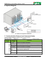
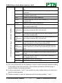
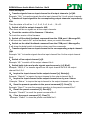
1
RGBHV/Stereo Audio Matrix Switcher 16x16 USER MANUAL MRG1616A PTN RGBHV/Stereo Audio Matrix Switcher 16x16 Version: MRG1616A2013V1.1 PTN Electronics Limited www.PTN-electronics.com RGBHV/Stereo Audio Matrix Switcher 16x16 NOTICE: Please read this user manual carefully before using this product. This manual is for operation instruction only, not for any maintenance usage. The functions described in this version are updated till May 2013. Any changes of functions and parameters since then will be informed separately. Please refer to the dealers for the latest details. This manual is copyright PTN Electronics Limited. All rights reserved. No part of this publication may be copied or reproduced without the prior written consent of PTN Electronics Limited. All product function is valid till 2013-05-29. Update History Version 1.0 1.1 Date 2010.01.01 2013.05.29 PTN Electronics Limited Update Content First Version. Modified the system diagram. www.PTN-electronics.com RGBHV/Stereo Audio Matrix Switcher 16x16 Table of Contents 1. Introduction ...............................................................................................................1 1.1. Introduction of MRG1616A ............................................................................1 1.2. Package Contents.......................................................................................... 1 1. Features .................................................................................................................... 1 2. Specification ..............................................................................................................1 3. Operations of the Control panel and the Remote Controller .....................................3 4.1. Operation of the Control Panel ......................................................................3 4.2. Usage of the Remote Controller ....................................................................4 5. External Connection ..................................................................................................6 5.1. Interface Introduction ..................................................................................... 6 5.2. RGBHV connection ........................................................................................ 6 5.3. Audio Signal Connection ................................................................................7 5.4. Connection with RS232 Communication Port ................................................8 5.5. Connection with Computer.............................................................................8 6. System Diagram........................................................................................................9 7. Communication Protocol and Command Codes ....................................................... 9 8. Safety Operation Guide ........................................................................................... 12 9. Troubleshooting & Maintenance .............................................................................. 13 10. After-sales Service .................................................................................................. 14 PTN Electronics Limited www.PTN-electronics.com RGBHV/Stereo Audio Matrix Switcher 16x16 1. Introduction 1.1. Introduction of MRG1616A MRG1616A is a 16x16 RGBHV matrix switcher following with stereo audio. It supports audio follow and audio breakaway switching. With bandwidth up to 450MHz (-3db), it supports cross-point switching. It shows a good application in broadcast room, television teaching room, commanding center etc. 1.2. Package Contents 1 x MRG1616A 1 x Power cord 1 x IR remote (The cell battery is not included) 32 x Captive screw connectors 4 x Plastic cushions 1 x RS232 cable 1 x User manual 1. Features Video bandwidth up to 350MHz. Audio follow or audio breakaway switching. Fast switching speed in 200ns. Power-fail protection, allows switcher restore to previous settings. 10 presets to save and recall switching patterns. Front panel lockout. Controllable via button, IR & RS232. 2. Specification Video Input Input Input Connector Return Loss Input Level Input Impedance DC Offset Video Output Output Output Connector Return Loss Output Level Output Impedance Switching Type 16 RGBHV Female BNC <-30dB@5MHz 0.5 ~ 2.0Vp-p 75Ω/510Ω(switchable) 1.5V 16RGBHV Female BNC -30dB@5MHz 0.5 ~ 2.0Vp-p 75Ω/510Ω(switchable) Vertical interval Video General Gain 0 dB Bandwidth Video Signal RGBHV, RGBS, Video Type PTN Electronics Limited 1 450MHz (-3dB), fully load RGBHV, RGBS, www.PTN-electronics.com RGBHV/Stereo Audio Matrix Switcher 16x16 RGsB, RsGsBs, component video, S-video, and composite video. Switching Speed Audio Input Input Input Connector Input Impedance Audio General Frequency Response Stereo Channel Separation Control Parts Serial Control Port IR Remote Options General Power Supply Temperature Case Dimension RGsB, RsGsBs, component video, S-video, and composite video . 200ns (Max.) Crosstalk <-80dB@5MHz Audio Output 16 stereo, balanced/unbalanced Captive screw connectors, 5 pole Output Output Connector Output Impedance >10KΩ 16 stereo, balanced/unbalanced Captive screw connectors, 5 pole 50Ω 20Hz ~ 20KHz CMRR >90dB@20Hz~20KHz >80dB@1KHz THD + Noise 0.03%@1KHz at nominal level RS232, 9-pin female D connector Pin 2 = TX, 3 = RX, 5 = Configurations GND Front Panel Default IR remote Buttons Control TCP/IP control by PTNET(PTN's programmable interface) 100VAC ~ 240VAC, 50/60Hz -20 ~ +70℃ W483 x H270 x D266mm (6U high, full rack wide) PTN Electronics Limited Power Consumption Humidity Product Weight 2 40W 10% ~ 90% 9.3Kg www.PTN-electronics.com RGBHV/Stereo Audio Matrix Switcher 16x16 3. Operations of the Control panel and the Remote Controller 4.1. Operation of the Control Panel ① Input Channel ②Output Channel ③Function Buttons F4-1 Front Panel Detailed Description: Buttons INPUTS OUTPUTS AV VIDEO AUDIO ALL ④Power indicator & IR Function Description Input buttons, ranging from "0" to "9". 16 channels in total. Output buttons, ranging from "0" to "9".16 channels in total. AV synchronal button: To transfer video and audio signal synchronously by the switcher. Example: To transfer both the video and the audio signals from input channel No.3 to output channel No.4. Operation: Press buttons in this order “AV”, “3”, “4””. Video button: To transfer only video signals from input channel to output channel Example: To transfer video signals from input channel No.3 to output channel No.4. Operation: Press buttons in this order “VIDEO”, “3”, “4”. Audio button: To transfer only audio signals from input channel to output channel Example: To transfer audio signals from input channel No.2 to output channel No.3. Operation: Press buttons in this order “AUDIO”, “2”, “3” All button: To transfer an input channel to all output channels. Example1: To transfer video and audio signals from input PTN Electronics Limited 3 www.PTN-electronics.com RGBHV/Stereo Audio Matrix Switcher 16x16 UNDO channel No.7 to all output channels. Operation: Press buttons in this order “7”, “ALL”. Example2: To transfer all input signals to the corresponding output channels respectively. In another word, to switch to this status: 1->1, 2->2, 3->3, 4->4……16->16. Operation: Press buttons in this order “ALL”, “THROUGH”. Undo button: To resume to the status before the command just performed. Backspace button: To backspace the latest input button. Through button: To transfer the signals directly to the corresponding output channels. THROUGH Example: To transfer the signals from input channel No. 3 to their corresponding output channels. Operation: Press buttons in this order “3”, “THROUGH”. Note: With the front control panel, the switcher could be control directly and rapidly by pressing the buttons under below format. “Switch Mode” +“Input Channel” +“Output Channel” 1) “Switch Mode”: “AV”, “VIDEO”, “AUDIO” 2) “Input Channel”: Fill with the number of input channel to be controlled. 3) “Output Channel”: Fill with the number of output channels to be controlled. 4.2. Usage of the Remote Controller With the infrared remote controller, the matrix switcher could be control remotely. Because the function buttons on the remote controller are the same with the ones on the front control panel, the remote controller shares the same control operation and command format with the control panel. Operations of the remote controller are showed as follows. PTN Electronics Limited 4 www.PTN-electronics.com RGBHV/Stereo Audio Matrix Switcher 16x16 The inputs channels, from 0~9, and plusing “10+” for more. Menu, for switching source and function. The outputs channels, from 0~9, and plusing “10+” for more. F4-2 Panel of the Remote Controller PTN Electronics Limited 5 www.PTN-electronics.com RGBHV/Stereo Audio Matrix Switcher 16x16 5. External Connection 5.1. Interface Introduction ① ② ③ ④ ⑤ F5-1 Rear panel ⑥ Detailed description: No. ① Name RGBHV INPUTS ② AUDIO INPUTS ③ ④ RGBHV OUTPUTS AUDIO OUTPUTS ⑤ ⑥ RS232 AC100V~240V Description RGBHV input channels, 16 in total. Female BNC connector. Audio input channels, 16 in total. 5-pole captive screw connector. RGBHV output channels, 16 in total. Female BNC connector. Audio output channels, 16 in total. 5-pole captive screw connector. Serial control port, 9-pin female connector. Alternating current for power supply. 5.2. RGBHV connection The MRG matrix switchers support the Composite Video, Component Video (YPbPr), Super Video (YC) and VGA signal source. RGBHV signal output terminals or YC output terminals are needed in AV device; RGBHV signal output terminals are needed in VGA device. The BNC connector is shown as the figure below. PTN Electronics Limited 6 www.PTN-electronics.com RGBHV/Stereo Audio Matrix Switcher 16x16 Tip (+) Sleeve ( ) BNC Connector If the VGA device doesn’t with RGBHV output terminals, please convert the signals with a VGA to RGBHV switcher for getting high quality MRG output effects. Please use the special five core RGBHV signal cord to connect the input and output devices and connect the BNC connector R(red)、G(green) 、B(blue) 、H(horizontal) 、 V(vertical)carefully. Attention: Please make sure the RGBHV connectors from the source and to the destination should be in the same order, otherwise it world cause color loss or no output signal at all. 5.3. Audio Signal Connection Audio connection is little complicated than video. It has two kinds of connection: balanced and unbalanced. The balanced connection transmits a pair of balanced signals with two signal cords. Because interferences will have the same intensity and the opposite phases on the two signal cords, it will be counteracted in the end. For the low frequency extent of the audio signal, it would be easily interfered under long distance transmission. Therefore, as an anti-interference connection, it is mostly used in audio connection of special device. The unbalanced connection transmits signals only with a signal cord. Without counteraction, it can be interfered more easily. Accordingly, it is adopted for household appliance or some cases with low technical demand. The two kinds of connection are shown below. Tip Tip Sleeve Sleeves Tip Tip Sleeve Unbalanced Input Unbalanced Output Tip Ring Tip Ring Sleeves Tip Ring Sleeves Tip Ring Balanced Input Balanced Output Balanced/unbalanced Connection on Captive Screw Connector The connection should be selected is up to the interface of the device. When available, the balanced connection is the first choice. Before connection, please read the command or relevant demand in the user manual carefully. In some cases, maybe there PTN Electronics Limited 7 www.PTN-electronics.com RGBHV/Stereo Audio Matrix Switcher 16x16 is balanced in source signal end but unbalanced in the destination end. If in a nonstandard case, it is done to connect balanced for the balanced end and unbalanced for unbalanced end. But if in a standard one, the converter must be used to switch the signals as the same, balanced or unbalanced. 5.4. Connection with RS232 Communication Port Except the front control panel, infrared remote controller (Optional) and the Ethernet control (Optional), the MVG matrix switcher can be controlled from far-end control systems via the RS232 communication port. This RS232 communication port is a female 9-pin D connector. The definition of its pins is as the table below. No. 1 2 3 4 5 6 7 8 9 F5-2 9HDF Pin N/u Tx Rx N/u Gnd N/u N/u N/u N/u Function Unused Transmit Receive Unused Ground Unused Unused Unused Unused 5.5. Connection with Computer When the switcher connects to the COM1 or COM2 of the computer with control software, users can control it by that computer. To control the switcher, users may use the RS232 software. F 5-3 Connection between MRG matrix switcher and the computer PTN Electronics Limited 8 www.PTN-electronics.com RGBHV/Stereo Audio Matrix Switcher 16x16 6. System Diagram F6-1 MRG1616A system connection 7. Communication Protocol and Command Codes System Command Communication protocol: RS232 Communication Protocol Baud rate: 9600 Data bit: 8 Stop bit: 1 Parity bit: none Command Command Functions Types Codes /*Type; Inquire the models information. /%Lock; Lock the keyboard of the control panel on the Matrix. /%Unlock; Unlock the keyboard of the control panel on the Matrix. /^Version; Inquire the version of firmware /:Message Turn off the feedback command from the com port. It will Off; only show the “switcher OK”. /:Message Turn on the feedback command from the com port. On; Undo. To cancel the previous operation. PTN Electronics Limited 9 www.PTN-electronics.com RGBHV/Stereo Audio Matrix Switcher 16x16 Demo. [x1]All. All#. All$. [x1]#. [x1]$. [x1] V[x2]. Operation Command (PTN2.0 Command System) [x1] V[x2],[x3],[ x4]. [x1] A[x2]. [x1] A[x2],[x3],[ x4]. [x1] B[x2]. [x1] B[x2],[x3],[ x4]. Status[x1]. Status. Save[Y]. Recall[Y]. Clear[Y]. Switch to the “demo” mode, 1->1, 2->2, 3->3 … and so on. Transfer signals from the input channel [x1] to all output channels. Transfer all input signals to the corresponding output channels respectively. Switch off all the output channels. Transfer signals from the input channel [x1] to the output channel [x1]. Switch off the output channel [x1]. Transfer the video signals from the input channel [x1] to the output channel [x2]. Transfer the video signals from the input channel [x1] to the output channels [x2], [x3] and [x4]. Transfer the audio signals from the input channel [x1] to the output channel [x2]. Transfer the audio signals from the input channel [x1] to the output channels [x2], [x3] and [x4]. Transfer both the video and the audio signals from the input channel [x1] to the output channel [x2]. Transfer both the video and the audio signals from the input channel [x1] to the output channels [x2], [x3] and [x4]. Inquire the input channel to the output channel [x1]. Inquire the input channel to the output channels one by one. Save the present operation to the preset command [Y]. [Y] ranges from 0 to 9. Recall the preset command [Y]. Clear the preset command [Y]. Note: 1) [x1], [x2], [x3] and [x4] are the symbols of input or output channels ranged according to the model of the matrix switcher. If the symbols exceed the effective range, it would be taken as a wrong command. 2) In above commands, “[”and “]” are symbols for easy reading and do not need to be typed in actual operation. 3) Please remember to end the commands with the ending symbols “.” and “;”. PTN Electronics Limited 10 www.PTN-electronics.com RGBHV/Stereo Audio Matrix Switcher 16x16 Detail Examples: 1、Transfer signals from an input channel to all output channels: [x1]All. Example: “3All.” to transfer signals from the input channel No.3 to all output channels. 2、Transfer all input signals to the corresponding output channels respectively: All#. Then the status of it will be: 1->1, 2->2, 3->3, 4->4…, 16->16. 3、Switch off all the output channels: All$. Then there will be no signals on all the output channels. 4、Check the version of the firmware: /^Version; To check the version of the firmware. 5、Switch off the detail feedback command from the COM port: /:MessageOff; It will leave the “switch OK” as the feedback, when you switch the matrix. 6、Switch on the detail feedback command from the COM port: /:MessageOn; It will show the detail switch information when send the commands. 7、Transfer signals from an input channel to the corresponding output channel: [x]#. Example: “4#.” to transfer signals from the input channel No.4 to the output channel No.4. 8、Switch off an output channel: [x]$. Example: “4$.” to switch off the output channel No.4. 9、Switch both video and audio signals synchronously: [x1] B[x2]. Example: “2B2,3,4.” to transfer signal from the input channel No.2 to the output channel No.2,3,4. 10、 Inquire the input channel to the output channel [x]: Status[x]. Example: “Status3.” to inquire the input channel to the output channel No.3. 11、 Inquire the input channel to the output channels one by one: Status. Example: “Status.” to inquire the input channel to the output channels one by one. 12、 Save the present operation to the preset command [Y]: Save[Y]. Example: “Save7.” to save the present operation to the preset command No.7. 13、 Recall the preset command [Y]: Recall[Y]. Example: “Recall5.” to recall the preset command No.5. 14、 Clear the preset command [Y]: Clear[Y]. Example: “Clear5.” to clear the preset command No.5. PTN Electronics Limited 11 www.PTN-electronics.com RGBHV/Stereo Audio Matrix Switcher 16x16 8. Safety Operation Guide In order to guarantee the reliable operation of the equipments and safety of the staff, please abide by the following proceeding in installation, using and maintenance. The system must be earthed properly. Please do not use two blades plugs and ensure the alternating power supply ranged from 100v to 240v and from 50Hz to 60Hz. 1) Do not put the switcher in a place of too hot or too cold. 2) As the power generating heat when running, the working environment should be maintained fine ventilation, in case of damage caused by overheat. 3) Cut off the general power switch in humid weather or left unused for long time. 4) Before following operation, ensure that the alternating current wire is pull out of the power supply: Take off or reship any components of the equipment. Take off or rejoin any pin or other link of the equipment. 5) As to non-professional or without permission, please DO NOT try to open the casing of the equipment, DO NOT repair it on your own, in case of accident or increasing the damage of the equipment. 6) DO NOT splash any chemistry substance or liquid in the equipment or around. PTN Electronics Limited 12 www.PTN-electronics.com RGBHV/Stereo Audio Matrix Switcher 16x16 9. Troubleshooting & Maintenance 1) When the output image in the destination device connected to the MRG Matrix has ghost, such as the projector output with ghost, please check the projector’s setting or try another high quality connection cord. 2) When user cannot control the switcher by computer through its COM port, please check the COM port number in the software and make sure the COM port is in good condition. 3) When switching , there is no output image: Check with oscilloscope or multimeter if there is any signal at the input end. If there is no signal input, it may be the input connection cord broken or the connectors loosen. Check with oscilloscope or multimeter if there is any signal at the output end. If there is no signal output, it may be the output connection cord broken or the connectors loosen. Make sure the destination device is exactly on the controlled output channel. If it is still the same after the above checking, maybe there is something wrong in the switcher. Please send it to the dealer for fixing. 4) If the POWER indicator doesn’t work or no respond to any operation, please make sure the power cord connection is good. 5) If the output image is interfered, please make sure the system is earthed well. 6) If the static becomes stronger when connecting the video connectors, it may be due to the incorrect earthling of the power supply, Please earth it again correctly, and otherwise it would bring damage to the switcher. 7) If the Matrix cannot be controlled by the keys on the front panel, RS232 port or remote controller, the unit may has already been broken. Please send it to the dealer for fixing. PTN Electronics Limited 13 www.PTN-electronics.com RGBHV/Stereo Audio Matrix Switcher 16x16 10. After-sales Service 1) If there appear some problems when running the switcher, please check and deal with the problems reference to this user manual. Any transport costs are borne by the users during the warranty. 2) You can email to our after-sales department or make a call, please tell us the following information about your cases. Product version and name. Detailed failure situations. The system connections. 3) We offer products for all three-year warranty, which starts from the first day you buy this product (The purchase invoice shall prevail). 4) Any problem is same with one of the following cases listed, we will not offer warranty service but offer for charge. Beyond the warranty. Damage due to incorrectly usage, keeping or repairing. Damage due to device assembly operations by the maintenance company non-assigned. No certificate or invoice as the proof of warranty. The product model showed on the warranty card does not match with the model of the product for repairing or had been altered. Damage caused by force majeure. Remarks: For any more questions or problems, please try to get help from your local distributor, or email PTN at [email protected]. PTN Electronics Limited 14 www.PTN-electronics.com