1
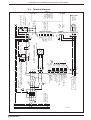
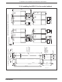
4. Control circuits
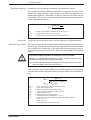
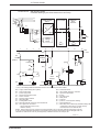
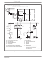
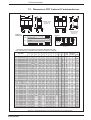
Control circuit: • without dynamic brake
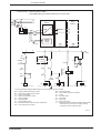
• controlled braking by the drive electronics in an E-stop
L1
L2
L3
Q10
T1
F1
L1
L2
L3
additional
drive
module
drive module
Supply module
KDV 2
power
section
Leistungsteil
L-
L-
L-
L+
L+
L+
K1
L1
L3
F2
1
control
voltage
supply
3
2
Bb
4
Bb
5
6
7
K3
S2
end
position
S1
E-Stop
+24V
+/- 10%
X10/6
KDV/Bb1
a
K1
T1
X10/7
1) K4
S4
OFF
NC
RF
b
Y1
U
S5
ON
K1
K1
K10
RF
drive
module
K3
U
Bb
K4
K4
U
U
K10
K4
0V
1) Only for feed drive holding brakes which are not controlled by the drive module.
Bb1 = supply module ready (drive system)
Bb = drive ready contact of drive module
F1 = fuse for input power
F2 = electronics and blower fuses
K1 = mains contactor
K3 = decoupling Bb1
K4 = holding brake control
K10 = decouple thermal contact for power transformer
NC = error signal from the control
Q10 = mains disconnect
RF = drive enable signal from controller
S1 = E-Stop
S2 = axis limit switch
S4 = power OFF
S5 = power ON
T1 = power transformer
Y1 = Take delay time of electrically released holding brake
of feed axes into account! Do not apply velocity
command until 100 ms after RF-ON!
SKDV23/2
Figure 4.5: Control circuits for KDV 2.3 without dynamic braking
• DOK-POWER*-KDV*2.3****-ANW1-EN-E1,44 • 06.97
33