1
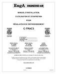
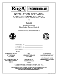
A
INSTALLATION, OPERATION
AND MAINTENANCE MANUAL
FOR
109 INTERFACE
MODULATING “ DG” BURNER CONTROL
INDOOR AND OUTDOOR MODELS
LIST E D
R
UNIT MODEL NO. ______________________________
UNIT SERIAL NO. ______________________________
SERVICED BY: __________________________________
TEL. NO: ______________________________________
CANADIAN
HEAD OFFICE
AND FACTORY
USA
HEAD OFFICE
AND FACTORY
CANADIAN
EASTERN
FACTORY
1401-HASTINGS CRES. S.E.
CALGARY, ALBERTA
T2G-4C8
32050 W. 83rd ST.
DESOTO, KANSAS
66018
1175-TWINNEY DRIVE
NEWMARKET, ONTARIO
L3Y-5V7
SALES OFFICES ACROSS CANADA AND USA
RETAIN INSTRUCTIONS WITH UNIT AND MAINTAIN IN A LEGIBLE CONDITION
PLEASE GIVE MODEL NO. & SERIAL NO. WHEN CONTACTING
FACTORY FOR INFORMATION AND/OR PARTS
FORM #109 INTERFACE 4.93
ENG A 109 INTERFACE
TO V9055
24V POWER SUPPLY
T T 8 9 B R W
W
1
R
140 OHM
POTENTIOMETER
B
1 2 3 4 5 6 7
*
2
INPUT
MAXITROL SERIES 14
* NOTE: If using a Maxitrol
system on a 109-1, terminals
1 and 2 need to be jumpered.
These terminals do not need
to be jumpered on the 109-2
The 109-1 and the 109-2 have the ability to accept a number of different control signals.
The 109 will process this signal and modify it to control a Honeywell V9055 valve.
The 109-1 and the 109-2 will accept the following input signals.
1
A 104 ohm slide wire system such as a Honeywell T991A.
2
A Maxitrol signal (usually series 14).
Further to this the 109-2 will accept a direct signal from a BMS system.
(4-20 MA or 0-10 VDC). Refer to the enclosed.
A 109 can be modified to accept this signal but is is recommended a 109-2 be substituted
for this application.
INSTALLATION, OPERATION
AND MAINTENANCE MANUAL
INDEX
PAGE
PURPOSE .........................................................................................................................1
OPERATION .....................................................................................................................1
CONTROL CONNECTIONS..............................................................................................3
TEMPERATURE CONTROL INPUT TERMINALS: ..........................................................3
MAXITROL SERIES 14 SYSTEM...............................................................................................3
MAXITROL SERIES 44 SYSTEM...............................................................................................3
T991A HONEYWELL OR OTHER SERIES 90 CONTROL .........................................................4
W973 and W7100 HONEYWELL CONTROLS...........................................................................4
CTRAC CONTROL ....................................................................................................................4
4 TO 20 ma INPUT FROM CONTROL DEVICE OR BMS SYSTEM ...........................................4
0 TO 10 VDC INPUT FROM CONTROL DEVICE OR BMS SYSTEM .........................................4
TROUBLESHOOTING ......................................................................................................5
NO FIRE ............................................................................................................................5
LOW FIRE BUT NO MODULATION .................................................................................6
OTHER NOTES.................................................................................................................6
Page i
109 INTERFACE
PURPOSE
The 109-2 Interface gives improved temperature control to a Engineered Air DG model unit. The
DG style unit uses a power burner that requires modulating air as well as modulating gas.
Therefore a valve such as a Honeywell V9055 or a motor such as a M9185 will be used to
modulate the flow of gas and air to the burner head. At periods when the temperature rise during
low fire setting is too high to properly control the discharge temperature, the 109 will cycle the
burner on and off.
There are two versions of the 109 interface. The original 109 will operate with a Honeywell series
90 temperature controller such as the fast response T991A. It will also operate with a Maxitrol
system such as the series 14. NOTE: when using the Maxitrol system on the 109, a jumper is
required on the 109 terminals 1 and 2. The 109 series 1 will also accept a signal from a
Honeywell W973 system.
The 109-2 is clearly marked as a 109-2. The 109-2 interface will allow the gas valve system to be
controlled by a Honeywell T991A fast response control, a Maxitrol system, a Honeywell W973
system, a signal from a Engineered Air Megatrac control, a 0-10 VDC or a 4-20ma control.
NOTE: only the 109-2 will handle the latter signals.
OPERATION (SIMPLIFIED)
Once the DG unit is running and the prepurge timing system has completed its cycle, the control
of the discharge temperature is handled by the 109 interface. The 109 uses a 24 volt AC power
supply that is connected to terminals “H” and “N”. In most applications the burner motor will run
continuously when outside ambients are below about 60°F.
1.
On initial call for heat, the 109 closes a set of internal relay the heat call (usually labelled
“1HR”), which in turn closes its contacts (usually labelled “1HR1”). In most applications this
will energise the flame relay if the pre-purge relay is closed. The prepurge relay is located in
a separate circuit that begins a timing cycle after the combustion fan begins to run. In some
installations with a constant pilot, “1HR1” contacts will energise the gas valve contacts that
are located between the 109 terminals “8” and “9”. This gives power to the relay that controls
directly. The gas valve is usually a Honeywell V9055.
2.
Upon completing ignition and proving pilot, the modulation of the gas valve is controlled by a
discharge control feeding a signal into the 109. The 109 modifies this signal and in turn puts
out a signal to the gas valve. The valve will usually overshoot before the discharge control
begins to close the gas valve back towards a modulated fire. Depending on the temperature
rise required, the 109 will modulate the gas valve to maintain the desired setpoint
temperature. Note that the valve will not go to a setting and remain there. There are tow
styles of gas valve in use, the Honeywell V9055 and the servo-motor controlled Neo valve.
Due to the “step” control of the Honeywell V9055, it is not possible to lock on to a setting.
This valve will modulate constantly, usually through a stroke of 3/8” or less.
Page 1
Recently there has been the introduction of a servo-motor that is being used to modulate the
gas flow. The servo-motor operates a modified Neo valve. This will reduce hunting of the gas
modulating valve but it will not totally eliminate it. There will be a separate shutoff device
such as the Honeywell V4055.
3.
The nature of the DG burner does not allow it to go to a high turndown ratio. For this reason
it is necessary to control temperature rise at the low end of the burner by cycling the burner
on and off. After the 109 has modulated the burner to low fire, it will keep the contacts
between 8 and 9 closed for about 1 ½ minutes. This is to allow the discharge control to
modulate the burner just above low fire if required. If temperature rise is too high to “lock on”
to a low fire control point, the relay contacts between 109 terminals 8 and 9 will then open.
This shuts off the main control valve. Note that if the discharge control call for the modulating
valve to open above low fire after the valve has modulated back to low fire, this cancels any
timing that has begun. The 109 will begin the full 1½ minute timing again each time the
signal drives to low fire.
4.
Once the heat call has been completed and the 109 has timed out, the next call for heat will
begin at point 1 above. The 109 will allow a large number of ignitions to occur on the DG
unit, especially when it is cycling at minimum firing condition. There can be ignitions
occurring every 2 minutes. If one ignition fail, the flame supervision relay will lock out. This
will require manual resetting of the flame relay.
Page 2
CONTROL CONNECTIONS
24 VOLT SUPPLY – to 109 terminals T and T
INTERNAL RELAY TERMINALS – used to cycle the signal to the flame relay (or the gas valve)
are terminals 8 and 9 on the 109.
TEMPERATURE CONTROL INPUT TERMINALS:
Note – the 109 system is designed to operate with only one of the following discharge air control
signals connected at a time.
MAXITROL SERIES 14 SYSTEM
The Maxitrol system outputs a DC voltage signal from its terminals 5 and 6. This signal is
put into the 109 at the 109 terminals 5 and 6 respectively. This signal will vary as per the
following:
0-3 VDC low fire
3-13 VDC modulating fire
above 13 VDC is high fire
Note - the 109 requires a jumper across the 109 terminals 1 and 2 to operate with the
Maxitrol system. The 109-2 does not require this jumper as it is done internally.
The following readings were taken from a maxitrol system connected to a 109-2
High fire output from the Maxitrol system = about 34 VDC
High fire output not connected to the 109 = about 36.15 VDC
Full heat call, mod valve disconnected R – W = 1.9 VDC
R – B = 0 VDC
B – W = 1.9 VDC
Low fire, all the above go to 0 VDC
Full heat call, V9055 connected R – W = 1.9 VDC
R – B = 0 VDC
B – W =2.9 VDC
Low fire with V9055 connected R – W = 0.37 VDC
R – B = 1.1 VDC
B – W = 1.4 VDC
MAXITROL SERIES 44 SYSTEM
This is similar to the series 14 system above, but the series 44 output terminals “6” and
“7” connect to the 109 terminals “5” and “6” respectively. The Maxitrol system offers a
linear space reset feature. Most of the above series 14 readings will apply.
Page 3
T991A HONEYWELL OR OTHER SERIES 90 CONTROL
The series 90 controls are a 135-ohm control system that usually uses a liquid filled
capillary to move a wiper over the surface of the resistor to change the values between
two points. The T991 centre tap (R) connects to the 109 terminal 2. The T991 terminal
“W” connects to the “W” terminal on the 109 interface. The T991 terminal “B” connects to
the 109 interface terminal 4.
W973 and W7100 HONEYWELL CONTROLS
Output from the W973 heating terminals “R” and “W” can be connected to the 109
interface terminals “6” and “2” respectively. The 109 is also available to interface the
W7100 but requires a jumper across interface terminals 6 and 7 to speed up the interface
by making it more sensitive to the slow reacting heat ramp from the W7100.
CTRAC CONTROL
The Engineered Air CTRAC control is designed to operate with a heat output ramp from
CTRAC terminals “HT” and “B”. This is a 0 to 8 VDC signal with terminal 8 being the
positive terminal.
4 TO 20 ma INPUT FROM CONTROL DEVICE OR BMS SYSTEM
A separate underground transformer should be used on the 109-2 interface terminals “T
and T” to avoid any possible feedback signal from the 4-20ma device through a ground
signal. The input terminals on the 109-2 are 2 and 7 with 7 being the positive terminal.
When the input signal to the 109 is at the full 20ma, the voltage reading across 109
terminals “2” and “W” should read 2 volts + or – 0.25 volts.
0 TO 10 VDC INPUT FROM CONTROL DEVICE OR BMS SYSTEM
A separate underground transformer should be used on the 109-2 interface terminals “T
and T” to avoid any possible feedback signal from the 0-10 VDC device through a ground
signal. The input terminals on the 109-2 are terminals 1 and 7 with terminal 7 being the
positive terminal. When there is a 10 volt signal input to 109 terminals “1” and “7”, there
should be a reading across 109 terminals “2” and “W” of 2 volts + or – 0.25 volts.
Page 4
TROUBLESHOOTING
All the following steps are assuming the unit is not having flame failure problems. If the problem
you are trying to rectify is one that requires the flame relay needs to be reset, it is not likely the
109 is related. The only exception would be if the 109 relay contacts at the 109 terminals “8” and
“9” are intermittent. If you are having temperature control problems or not establishing power to
the flame relay because the 109 relay terminals are not closing, then the following is relevant.
In mot instances troubleshooting the 109 is a matter of determining if the problem is with the 109
or another component. It is usually best to determine this by breaking the system into component
sections. We recommend the following steps.
1.
Ensure there is a proper 24 VAC power supply to the 109 at the “T and T” terminals.
2.
Disconnect the temperature control device from the 109. After this is complete connect a
potentiometer to the 109 series 90 terminals. If possible use a 135-ohm or a 270-ohm pot. If
none of these are available you can use a slightly larger value pot or a series 90 modulating
control such as a T991A or T991E. The purpose of this is to prove the 109 and the
associated components connected downstream of it are working correctly. In most instances,
internal 109 failures will be revealed with this step.
Connections for the pot are as follows:
- Connect the pot centre tap to 109 terminal “2”.
- Connect the pot end terminals to the 109 terminals “4” and “W” respectively.
- Turning the pot one direction should create a call for heat and turning the pot the
other direction should stop the call for heat. It should be possible to modulate the
control in between these points to obtain any mid range firing position.
3.
Assuming the above works properly, the 109 and the components located downstream
(relays, gas valves etc.) are all operating to satisfaction. If a problem returns when the
original temperature control device is connected, check the temperature control device for
faults. If the system still did not operate to satisfaction when operated as in step 2 above,
shut the unit off and go to step 4.
4.
If the 109 did not modulate the gas valve properly, remove the pot from the 109 and connect
the pot to the modulating section of the gas valve. The centre tap of the pot will connect to
the “R” terminal of the modulating valve. Connect the other two pot terminals to the “W” and
“B” terminals of the modulating valve. When the unit is again fired and power is reestablished to the modulating valve, the modulating valve should now be able to be
modulated by the pot. Turning the pot up and down should cause the valve to open and shut.
NO FIRE
This test is to ensure the 109 relay terminals “8” and “9” are closing. Insure 24 VAC supply is to
the 109. Disconnect the discharge control wires and simulate a call for full heat by the following.
Jumper 109 terminals “2” and “4”, or set the test potentiometer (described at point 2 above) on
the 109 to the setting that reduces the resistance across the 109 terminals “2” and “4” to zero.
This should cause the 109 to go to a call for high fire and close the relay terminals “8” and “9” to
energize the heat relay. Note there are other relays in the heat circuit that must also be closed to
activate the flame relay. If the flame relay got proved pilot, then the burner should go to at least a
low fire setting when the flame relay activates the main valve. If the 109 did not close the relay
terminals “8” and “9”, replace the 109.
Page 5
LOW FIRE BUT NO MODULATION
The modulating valve should be able to be modulated to any position after the 109 contacts are
closed and the main flame is established. If the valve will modulate when a potentiometer is
connected to the 109 as described in point 2 above but it will not modulate from the normal
temperature controller, it is likely the normal temperature controller is at fault.
OTHER NOTES
A) If using a 0-10 VDC or a 4-20 ma signal to the 109, ensure the 24 VAC power to the 109
terminals “T and T” is from a separate underground transformer. The wires to the BMS
supply signal should be run in a separate shielded cable with the shield grounded at the unit
end only. This is to reduce interference.
B) With all wires except the “T and T” terminals disconnected and 24 volt power to those
terminals, the 109 should have about 15 VDC across the 109 terminals “4” and “W”.
C) With a 135 ohm pot connected as in point 3 above, the voltage across 109 terminals “4” and
“W” (-) should modulate between 1.75 and 4.5 VDC depending on the pot setting.
D) With a 135 ohm pot connected as in point 3 above, the voltage across 109 terminals “2” and
“w” (-) should modulate between 0 and the reading found in point ‘C’ above. (0 = low fire).
E) With a 135 ohm pot connected as in point 3 above, the voltage across 109 terminals “R” and
“W” (-) should modulate between 0 VDC and 2.5 volts at high fire, depending on the pot
setting.
F) Adjust the pot setting. When the voltage across the 109 terminals “R” and “W” is in excess of
about 1 VDC, the 109 relay contacts “8” and “9” should close. These contacts should remain
closed for about 1 ½ minutes after the voltage is reset to 0 and the internal timer completes
its cycle.
Page 6