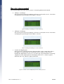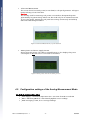
1
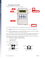
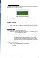
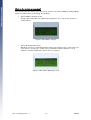
A511 Sensor & SolarPanel Test box
This document describes the A511 Sensor & Solar Test box. It will facilitate rapid
testing of Adcon compatible sensors and solar panels, and assist you in
configuring SDI-12 sensors.
A511 User Manual, Rev. 1.1
08/2007
Table of Content:
1.
Description of the A511.......................................................................... 3
2.
Switching the A511 ON and OFF............................................................ 4
3.
Quick Start ............................................................................................. 4
4.
5.
3.1.
How to test analog sensors........................................................................4
3.2.
How to test the power consumption of Sensors ........................................5
3.3.
How to test a solar panel ...........................................................................5
3.4.
Changing the address of SDI-12 sensors....................................................5
The operating modes of the A511 .......................................................... 6
4.1.
Analog Measurement Mode.......................................................................7
4.2.
Configuration settings of the Analog Measurement Mode ........................9
4.3.
SDI-12 Address Change Mode .................................................................11
Technical Specifications ........................................................................ 13
A511 User Manual, Rev. 1.1
-2-
08/2007
1.
Description of the A511
The image shows the major elements of the A511:
Port 2
Display
Port 3: Solar Panel &
SDI-12 Connector
Port 1
Foil Keypad
In the rear:
Battery Case
Port 1: a female 7-pin M9 connector on the left side of the device for testing analog sensors
Port 2: a female 7-pin M9 connector on the upper right side of the device for testing analog
sensors
Port 3: a female 5-pin M9 connector on the lower right side of the device used for a) checking or
changing SDI-12 addresses and b) testing solar panels
Connectors on the A511 are identical to those used with all Adcon A720, A723, A732 and A733
RTUs so all Adcon analog sensors and solar panels can be connected without any adapters.
The 7-pin connectors are used for analog readings as described in Section 4.1. These connectors
have the same pin-out as the RTU’s mentioned above:
•
3 analog inputs: Cabling 1, Cabling 2, Cabling 3
•
1 counter input “CNT”
•
1 digital input “DIG”
Pin out of the two connector types:
Switched Battery
Digital I/O
Cabling 1
Cabling 2
Ext. Power
7 1
6
2
5 4 3
Pulse
Counter
5
4
1
Battery
Cabling 3
RxD
3 2
TxD
Ground
Ground
Figure 1: Pin out of Ports 1 and 2
Figure 2: Pin out of Port 3
A511 User Manual, Rev. 1.1
-3-
08/2007
The A511 features two 7 pin testing ports. The outputs from each port are assigned different
names to properly identify the readings. For uniformity we will therefore stick throughout this
manual with the naming conventions as outlined in the following table:
7-pin connector on A511’s
Port 1 (left)
Port 2 (right)
analog inputs
Cabling 1, 2, 3
Cabling 4, 5, 6
counter inputs
Counter1
Counter2
DIG1
DIG2
digital inputs
2.
Switching the A511 ON and OFF
The A511 is switched ON by pushing the “Menu ON” key.
(Due to the layout of the keypad pushing the “F3” key can also turn on the A511, but this is not
recommended.)
By default the A511 will turn itself OFF after 60 seconds of inactivity that is with no keys pressed.
When this occurs you will receive a message stating “Turn off the device! To abort press any
key.” You have three seconds to press a key to stop shutdown.
To turn the A511 OFF manually simply push and hold down the “Menu ON” key for at least 2
seconds. You will get the same message to have a chance to abort the shutdown.
Attention:
Auto-Shut-OFF will not work with the unit set to permanent monitoring mode!
3.
Quick Start
This section of the manual will give you a quick overview of the most frequently used functions.
3.1. How to test analog sensors
•
Make sure a standard 9V battery is inserted into the battery case in the rear of the
device.
•
Switch the unit on by pushing the “Menu ON” key.
•
Skip “Loading last Menu settings” by pressing the “F3” key.
•
Connect your sensor to Port 1 on the left hand side of the A511. You will
immediately see how the readings in the display will change.
Note: As long as no sensors are connected the readings will remain at 0.0%.
Attention:
If you are using Port 2 rather then Port 1, you will have to switch to the corresponding
display by pressing the “F2” key.
For detailed information please check chapter 4.1.
A511 User Manual, Rev. 1.1
-4-
08/2007
3.2. How to test the power consumption of Sensors
Testing for sensor power consumption is useful if you observe the RTU battery not charging
normally. If the solar panel is located in a sunny location and oriented properly then it is
possible that a defective sensor or short may cause excessive power draw.
The A511 will let you test how many mA either analog or SDI-12 sensors are drawing
•
Turn the A511 on by pressing the “Menu ON” key.
•
Skip “Load last Menu settings?” by pushing the “F3” key.
•
Press the “F2” key. The display will now show the power consumption screen. In the
top line of the screen you can see the voltage rating of the internal battery, while
the second line will show you the current uptake of aLL currently attached sensors.
•
Example: an Adcon SEN-R combi-sensor for air temperature and humidity has a
typical uptake of less than 4mA. The display will show a value like 0.004 A or less.
Note: An aging battery as well as an aging or dirty solar panel could cause similar
symptoms. If the sensor power consumption is normal then see the next section
for testing solar panels.
3.3. How to test a solar panel
•
Turn the A511 on by pressing the “Menu ON” key.
•
Skip “Load last Menu settings?” by pushing the F3 key.
•
Press the F1 key. The display will show the solar panel test screen.
•
Connect the solar panel to Port 3 at the right side of the A511.
•
Now watch for the change on the A511 display (also see Fig. 8, page 9).
Note: To see the full capacity of your solar panel the test must be performed on a sunny day.
Make sure to orient the panel perpendicular to the to the sun (an angled orientation
will diminish the solar panel output).
The following table will give you a few examples of what you can expect from a properly
performing solar panel on a moderately sunny and a rather cloudy day:
Model
Sunny (~950W/m²)
Cloudy (~50W/m²)
120mA
2,5 V / 111mA
0,3V / 28mA
300mA
6.8V / 309mA
2V / 95mA
460mA
9.2 V / 420mA
4.4V / 180mA
Scratched or weathered solar panels have diminished charging capability. Charging
capability can be maintained/improved by polishing the surface with Adcon Solar Cell
Cleaner (item number 800.000.400.)
3.4. Changing the address of SDI-12 sensors
The A511 provides the ability to check and modify addresses on SDI-12 sensors. You will
need the SDI-12 adapter cable (optional; item number. 800.511.001).
A511 User Manual, Rev. 1.1
-5-
08/2007
Caution:
Please check the specification of your SDI-12 device. Unless you are using an SDI-12 sensor
with internal battery packs, it will be powered by the A511, and will therefore have to work
with a supply voltage lower than specified in the SDI-12 standard (also see Section 5 – SDI-12
sensor specification).
How to determine and change SDI-12 settings:
•
Switch the A511 ON by pushing the “Menu ON” key.
•
Skip “Load last Menu settings?” by pressing the “F3” key.
•
Connect your SDI-12 sensor to Port 3 NOW, prior to pushing any other key, by
means of your SDI-12 adapter cable.
•
Push the “SDI Mode” key on the A511. The A511 will connect to the SDI-12 sensor,
read its address and display it on the screen.
Note: If an error message occurs, press the “SDI Mode” key again. Such an error usually
occurs because the sensor is in low-power mode and is not responding fast enough.
•
•
Modify the sensor’s address settings by pushing either the “F1” or the “F3” key.
Pushing “F1” will get you to the next higher addressPushing the “F3” key will lower
the address by one step. Each keystroke will get your address one step up or down.
Repeat until you see the desired address on the display.
Once you have set the desired address push the “F2” key. The A511 will transmit
the new address setting to the SDI-12 sensor, request an acknowledgment and
display its new address in the top line of the A511 display.
Note: As defined in the SDI-12 specification all addresses must be alphanumerical. While
the A511 provides the full range according to the standard, some SDI-12 sensors
also support non-standard address settings. An error will occur if you attempt to
send an illegal address to the sensor.
4.
The operating modes of the A511
Two different screens will be displayed during the startup sequence of the A511. The initial
startup screen will show the firmware version of your A511, which you will need to know in case
you need support with your A511.
Figure 3: Initial Startup Screen
The second screen will ask you if you want to load the last menu settings saved. By default the
settings will automatically be saved once you are exiting the menu for analog measurements (see
below for further information). Should you want to load the previous settings push “F1”, else
push “F3” to start with default settings.
A511 User Manual, Rev. 1.1
-6-
08/2007
Figure 4: Load settings screen at startup sequence of A511
The A511 has two operating modes:
•
The Analog Measurement Mode
•
The SDI-12 Sensor Address Changer Mode.
4.1. Analog Measurement Mode
This mode is for measuring analog sensors, which are connected to Ports 1 and 2, and for
solar panels connected to Port 3. By default the A511 will start up in this mode.
In order to see the readings of all three ports you need to toggle between the various
screens as described below.
The way measurements are being taken is corresponding to the settings in the Analog
Measurement Menu as described in section 4.1. By default the device is set to
• no permanent supply – auto-shutdown function of A511 activated
• permanent measurement of sensors
• no Averaging
Caution:
This is the right setting for most sensors, which are capable of continuously updating and
outputting their readings, like temperature or wind speed settings. Since ADCON RTU’s do
not use such a setting, we have also implemented the Adcon measurement procedure,
which can be activated through the Analog Measurement Menu. Certain sensors, like the
Watermark sensor and the WindMAX device, need to be triggered to output a value.
Using the Keypad to toggle between functions and screens
The A511 has a 6-key keypad due to limited space. Thus most keys support at least two
functions. To toggle between functions just press again.
•
“F1”: Function 1: shows “Cabling 1 to Cabling 3” (Figure 5)
Function 2: shows “Solar panel measurement” ( 8)
•
“F2”: Function 1: shows “Cabling 4 to Cabling 6” (Figure 6)
Function 2: shows “Battery Status & Current Sensing” (Figure 9)
•
“F3”: Function 1: shows “Counter and digital input 1 & 2” (Figure 7)
Function 2: will reset counters 1 and 2 (hold key down for two seconds!)
•
“SDI Mode”: Switches to “SDI-12 Address Changer Mode”
•
“Menu ON”: Function 1: Enters or Exits the Configuration Menu.
Function 2: Shuts the device OFF. Hold key down for two seconds!
A511 User Manual, Rev. 1.1
-7-
08/2007
What do the various screens show?
The following figures show the various screens of the Analog Measurement Mode.
•
Cabling 1 to Cabling 3
This screen shows the analog readings of all sensors connected to Port 1. The values
are displayed as percentages, where 100% = 2.5 Volts.
Figure 5: Cabling 1 to Cabling 3, no sensors attached
•
Cabling 4 to Cabling 6
This screen shows the analog readings of all sensors connected to Port 2. The values
are displayed as percentages, where 100% = 2.5 Volts.
Figure 6: Cabling 4 to Cabling 6, no sensors attached
•
Counter and digital inputs
Shows the sum of all pulses that were detected while a pulse output device (like a
rain gauge or a water meter) was connected to Port 1 and/or 2. It also shows
whether the digital input is active (“1”) or inactive (“0”). By default when connecting
a digital TTL status signal generator the display will show a “1” when a signal is
detected, and a “0”, when no signal is detected.
Figure 7: Counters 1 & 2 and digital inputs 1 & 2, nothing attached
A511 User Manual, Rev. 1.1
-8-
08/2007
•
Solar Panel Measurement
This screen shows how much power (in V and mA) a solar panel generates. Voltage is
measured using a load of 22 Ohm.
Caution:
The circuitry used for measuring solar power is not made to dissipate the power
generated by long term testing. Please use this mode only for an instantaneous test
of your solar panel! Leaving the solar panel test running continuously can build up
heat and could damage the A511.
Figure 8: Solar Panel Measurement, no panel attached
•
Battery Status and Sensor Supply Current
Shows the power status of the A511’s internal battery. It also displays the power
consumption of ALL the sensors connected to the device.
Figure 9: Battery status and current used by sensors
4.2. Configuration settings of the Analog Measurement Mode
The Default Settings of the A511:
• „Perm.Supply“ = Permanent Operation OFF - auto-OFF after 60 seconds ON
• „Meas.“ Measuring Method = Permanently Update sensor readings
• „AVG“ Averaging = OFF, do not average readings
A511 User Manual, Rev. 1.1
-9-
08/2007
Customizing the Default Settings:
To start the configuration Menu press the “Menu ON” key once. You will see the following
three parameters on the screen of your A511:
Figure 7: Analog Measurement option screen
The top entry displays the status of the Permanent Power Supply setting,
the centerline displays the status of the Measurement Mode, and
the bottom entry displays the status of the Average Measurement Mode.
Permanent Power Supply:
Toggle between the two options by pushing the F1 key:
•
“OFF” – the A511 will auto-shut down after 60 seconds, if no keys are pushed.
•
“ON” – the A511 will not shut down automatically. To shut if OFF press the “Menu
ON” key for 2 seconds and release. This mode is useful for tasks like
normalizing C-Probes.
Measurement Mode:
Toggle between the two options by pushing the F2 key:
•
“permanent” – the device will permanently sample sensors, about 60 - 70 times per
second, and display each reading.
•
“after 2s” – the supply voltage of the sensors will be turned on for approx.
2 seconds and afterwards turned off for approx. 3 seconds. The
measurement will be started at approx. 1.8 seconds, and the very last
reading prior to turning the supply voltage off again is displayed. This
simulates the way an Adcon RTU samples sensors. It avoids quickly
fluctuating values, and facilitates the recognition of erroneous sensor
behavior. The fluctuations of values should be limited to overall accuracy
of the sensor.
Average Measurement Mode:
Toggle between the two options by pushing the F3 key:
•
“OFF” – only the last reading will be taken and displayed.
•
“ON” – ten readings will be taken and the arithmetical average value will be
displayed.
A511 User Manual, Rev. 1.1
- 10 -
08/2007
Combination of Modes
You can certainly combine measurement methods. Setting Measurement Mode “Meas.” to
“after 2s” and turning “AVG” ON will cause the A511 to power the sensor, warm it up for
1.8 seconds, take 10 readings, display their average, and turn the sensor off again. This cycle
will then repeat after 3 seconds.
Exit and Save the Configuration Menu
To exit the configuration Menu press the “Menu ON” key once. The A511 will go back to the
Analog Measurement Mode. The settings will automatically be saved. The next time you
switch the device ON again you will be asked if you want to restore these settings.
4.3. SDI-12 Address Change Mode
To change the address of an SDI-12 sensor attach the optional cable 800.511.001 to Port 3.
The SDI-12 Address Changer is conforming to the SDI-12 standard, Ver. 1.3. However, the
sensor attached needs to adhere to Adcon’s extended SDI-12 supply voltage specification
(see Section 5 – SDI-12 sensor specification) if you want to A511 to power the sensor.
Caution:
Do not operate with more than one SDI sensor simultaneously, else the Address Change
Mode will not work
Entering SDI-12 Address Change Mode
Switching to the SDI-12 Address Changer Mode is done by pushing the “SDI Mode” key
while being in the Analog Measurement Mode. Be sure that a sensor is connected by means
of the 800.511.001 adapter cable, else an error message will be displayed.
Using the Keypad to toggle between functions and screens
Again, keys have different functionality. Here is what they will do:
•
“F1”: Increases the sensor address by one step per push.
(see SDI–12 Ver.1.3 specification for conforming sensor addresses)
•
“F2”: Will commit the sensor address you chose to the SDI-12 sensor and return an
acknowledgement of the newly set address.
•
“F3”: Decreases the sensor address by one step per push.
(see SDI–12 Ver.1.3 specification for conforming sensor addresses)
•
“Meas. Mode”: Pushing this key will end the “SDI-12 Address Change Mode” and
switch the A511 into the Analog Measurement Mode.
•
“SDI Mode”: When being in SDI Mode a short push on this key will again send an
address request to the sensor.
A511 User Manual, Rev. 1.1
- 11 -
08/2007
What do the various screens show?
The following Figures will show you the various screens of the SDI-12 Address Change Mode.
(Please note that values and settings are variable!)
•
SDI-12 Address Change screen
Change and commit the new address by pushing the “F1”, “F2” and “F3” keys as
outlined above.
Figure 8: SDI address changer
•
SDI-12 Error Message screen
Will show if an error occurred during the transaction with the sensor. This is the case
if the sensor is reacting too slowly to the commands issued by the A511 or if an
address is committed which the sensor does not support.
Figure 9: SDI-12 Error Message screen
A511 User Manual, Rev. 1.1
- 12 -
08/2007
5.
Technical Specifications
Power Supply
•
A 9 volt block, alkaline or rechargeable battery
Maximum ratings
Inputs
•
7 pin Ports 1 and 2:
Input
•
max.
unit
Analog Inputs (Cablings 1 through 6)
3.3
V
Counter Inputs (Counter1 and Counter 2)
3.3
V
Digital Inputs (DIG1 and DIG2)
3.3
V
max.
unit
Solar Panel Input
15
V
Digital Input (SDI Data)
10
V
5-pin Port 3
Input
Outputs (SBAT)
The SBAT voltage depends on the current energy status of the battery. (get status via
the energy status and sensor supply current).
Recommended ratings
Input
unit
Analog Inputs (Cablings 1 through 6)
Counter Inputs (Counter1 and Counter 2)
0 - 2.5V
V
3.3 pull-up
V
Digital Inputs (DIG1 and DIG2)
3.3
V
Solar Panel Input
12
V
SDI sensor specifications
Parameter
Sensor Supply Voltage (Vs)
min.
max.
unit
5,5
16
V
500
mA
5.5
V
Sensor Supply Current (Is)
Digital Input (SDI Data)
3.5
The SDI address changer supports sensor addresses between:
•
“0” and “9”
•
“A” and “Z”
•
“a” and “z”
Special characters are not supported.
For details or further information see the SDI -12 standardization datasheet
(http://www.sdi-12.org).
A511 User Manual, Rev. 1.1
- 13 -
08/2007