1
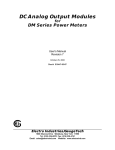
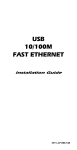
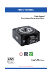
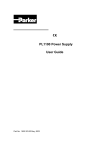
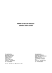
Compumotor VM24 Series User Guide External Input/Output Interface Module for 6000 Series Controllers Compumotor Division Parker Hannifin Corporation p/n 88-015965-01A July 1997 VM24 I/O Module Information in this document is subject to change without notice and does not represent a commitment on the part of Parker Hannifin Corporation. No part of this document may be reproduced or transmitted in any form or by any means, electronic or mechanical, including photocopying, recording, or information storage and retrieval systems, for any purpose other than the purchaser's personal use, without permission of Parker Hannifin Corporation. VM24 is a trademark of Parker Hannifin Corporation. Microsoft is a registered trademark and Windows is a trademark of Microsoft Corporation. Copyright 1997 by Parker Hannifin Corporation. All rights reserved. Printed in the United States of America. WARNING The VM24 I/O Module sends and receives signals for controlling your system's electrical and mechanical components. Therefore, you should test your system for safety under all potential conditions. Failure to do so can result in damage to equipment and/or serious injury to personnel. Technical Assistance: Contact your local ATC, or ... North America Europe Parker Hannifin Corporation Compumotor Division 5500 Business Park Drive Rohnert Park, CA 94928 Telephone: (800) 358-9070 or (707)584-7558 Fax: (707) 584-3793 BBS: (707) 584-4059 FaxBack: (800)936-6939 or (707) 586-8586 Internet: www.compumotor.com E-mail: [email protected] Parker Hannifin plc Electromechanical Division - Digiplan 21 Balena Close Poole, Dorset. BH17 7DX UK Telephone: +44(0)1202 69 9000 Fax: +44(0)1202 69 5750 Parker Hannifin GmbH & Co. KG Electromechanical Division - Hauser Rober-Bosch-Str. 22 D-77656 Offenburg, Germany Telephone: +49 (0)781 509-0 Fax: +49 (0)781 509-176 Product Feedback Welcome Motion & Control E-mail: [email protected] C O N T E N T S Chapter 1. Installation What You Should Have (ship kit) ...................................................2 Overview — VM24 .....................................................................3 Specification Summary ...............................................................4 VM24 Assembly Configuration......................................................7 I/O Pin Out Table .......................................................................8 Electrical Connections................................................................9 Jumper Configuration ............................................................... 11 Ribbon Cable Connection .......................................................... 12 Input Connection ..................................................................... 15 Output Connection................................................................... 16 VM24 Module Configuration Summary .......................................... 17 Chapter 2. Troubleshooting Troubleshooting Basics ............................................................ 20 SIM Board Installation and Removal ............................................ 23 1 C H A P T E R O N E Installation What You Should Have (ship kit) Part Name Part Number One of the following line items: VM24S single axis I/O module ...................................... VM24S VM24IN multi axis I/O module ...................................... VM24-IN VM24OUT multi axis I/O module.................................. VM24-OUT VM8/16 multi-axis I/O module....................................... VM8/16 VM16/8 multi-axis I/O module....................................... VM16/8 Ship Kit: This user guide (VM24 User Guide)............................. 88-015965-01A One of the following cables: Standard 50-pin ribbon cable ....................... 71-013016-01 (For VM-24S, VM24-IN, and VM24-OUT) Split 50-pin ribbon cable............................... 71-013016-01 (For VM8/16 and VM16/8) If an item is missing, call the factory (see phone numbers on inside front cover.) Options/Accessories Part Number Module base with Standard cable and User Guide ........................ VM24-Base1 Module base with Split cable and User Guide................................ VM24-Base2 Output SIM card (8 outputs)............................................................ SIM8-OUT Input SIM card (8 inputs)................................................................. SIM8-IN Input/Output SIM card (4 inputs, 4 outputs)..................................... SIM8-4X4 2 VM24 I/O Module Overview — VM24 The VM24 external I/O modules act as an interface for the general-purpose programmable inputs and outputs of all the 6000 Series servo and microstepping products. The VM24 module consists of a base board and one to three SIM (single in-line module) style boards that can be inserted to provide the user with a scaleable solution for their input and output needs. • The outputs are enhanced by an undervoltage lockout circuit and a thermal shutdown protection circuit. These outputs operate over 5VDC to 24VDC, will sink 50 mA to 0.4VDC or 300mA to 2.5VDC, and will source 50 mA to a voltage level of Vo – 2VDC (user-supplied voltage level Vo minus 2 volts, e.g. for Vo=24V, output is 22V) or 300 mA to a voltage level of Vo – 2.5VDC (user-supplied voltage level Vo minus 2.5 volts, e.g. for Vo=24V, output is 21.5V). • The inputs are enhanced by decompression, hysteresis, high-frequency filtering, and overvoltage clamping. These inputs, capable of operating in sinking or sourcing mode, have a range from 5VDC to 24VDC. The switching level for inputs is based on the user-supplied voltage Vi, such that OFF ≤1/3 (Vi) and ON ≥ 2/3 (Vi), with hysteresis of 1/3(Vi). (For example, with Vi of 24VDC, OFF ≤ 8VDC and ON ≥ 16VDC, with 8VDC of hysteresis.) Jumpers are used to configure the inputs as sinking or sourcing. Each of the three SIM sockets has its own corresponding jumper, allowing each input SIM to be independently configured. The VM24 module accepts a 50-pin ribbon cable from the 6000 Series product and provides screw terminal connections for easier interface with the user's application. The 24 I/O signals to/from the 50-pin DIN connector and the 50-pin screw terminal are interrupted by three SIM sockets (each SIM interrupts an 8-bit group of signals). Optical isolation is inherited from the 6000 product, except for OEM products. (I/O ground is isolated from microprocessor ground, but inputs and outputs are not isolated from each other.) Installing the VM24 3 Specification Summary Parameter Specification Power Requirements V o ........................ User-supplied voltage that drives output circuitry. Vo does not affect input circuitry, so it is not necessary for the VM24-IN. V o Range................ 5-24VDC Vo Current.............. 144mA, plus the sum of the load currents outputs that are in sourcing mode. V i .......................... User-supplied voltage that drives input circuitry & determines switching levels for inputs. Does not affect output circuitry, so it is not necessary for the VM24-OUT. Vi Range ................ 5-24VDC V i Current............... 1.5mA per volt of Vi (e.g., 15mA for Vi=10V) +5V ....................... Supplied by the 6000 Series Controller/Indexer through the 50-pin ribbon cable to connector J4. The VM24 draws 0.25mA per active output and 0.5mA per active input. Also provides the +5V output power available through the VM24 screw terminal block J5. Inputs Switching levels ....... LOW ≤ 1/3 (V i ) HIGH ≥ 2/3 (Vi) Voltage Range.......... 0-24V. Voltage of input signals should not exceed voltage level of Vi. (Input circuitry of VM24 has diodes to protect against voltages that exceed Vi, but performance may degrade.) Sinking Current:....... Connect jumper for desired socket to position 3 (default) Sourcing Current: ..... Connect jumper for desired socket to position 1 4 VM24 I/O Module Impedance................ 6 kΩ, minimum. Requires input current (sourcing or sinking) of 0.111mA per volt of user-supplied voltage Vi. (e.g., 1.11mA for Vi=10V). Status:.................... Check with the TIN or INFNC command. Active Level: ........... Set by 6000 Series Controller/Indexer. Default is active low, but can be changed to active high with the INLVL command. Input frequency......... 50 kHz (the maximum frequency is limited practically to 500 Hz by the 2 ms update rate of the 6000 Series. Outputs Voltage ................... Sourcing Current Output voltage level is 2 volts less than the usersupplied voltage Vo when sourcing up to 50mA. (Vo – 2 VDC for 50 mA e.g. for Vo=24V, output is at 22V) Output voltage level is 2.5 volts less than the user-supplied voltage Vo when sourcing up to 50mA. (Vo – 2.5VDC for 300 mA e.g. for Vo=24V, output is at 21.5V) Sinking Current Output voltage level is less than or equal to 0.4VDC when sinking up to 50mA. (≤ 0.4 VDC for 50 mA) Output voltage level is less than or equal to 2.5VDC when sinking up to 300mA. (≤ 2.5 VDC for 300 mA) Current ................... 300mA maximum per output, continuous duty at 50°C ambient temperature Status:.................... Check with the TOUT or OUTFNC command. Active Level: ........... Default is active low, but can be changed to active high with the OUTLVL command. Rise Time ............... Load dependent; typically 40ns per 1000 pF Fall Time................ Load dependent; typically 40ns per 1000 pF Installing the VM24 5 Undervoltage Protection......... The under-voltage lockout circuit is meant to prevent the output driver from sinking or sourcing unless the user-supplied voltage Vo is between 5VDC and 24VDC. Thermal Shutdown.... The thermal shutdown protection is intended to protect the device from marginal environmental factors. It must not be considered short circuit protection. The thermal resistance between the FET junction and the thermal protection circuit on the SIM cards is great enough that the rapid rise in junction temperature caused by a short circuit will not transfer fast enough to protect the device from damage. +5V Output............. Supplied by the 6000 Series Controller/Indexer through the 50-pin ribbon cable to connector J4. Accessed on the VM24 through the screw terminals (J5). Refer to the User/Installation Guide for the 6000 Series Controller/Indexer being used for the load limit of its +5V Output. Subtract any loads being drawn from the +5V Output at the 6000 Series unit level. The VM24 draws 0.25mA per active output and 0.5mA per active input from the +5V supply. Use this information to calculate the load limit available for the +5V Output on the screw terminal of the VM24. NOTE: Outputs are not short-circuit protected. Environmental Operating Temp........ 32 to 122°F (0 to 50°C) Storage Temp........... -22 to 185°F (-30 to 85°C) Humidity................. 0 to 95% non condensing Dimensions SIM board ............... 1.1 inches x 4.25 inches (28 mm x 108 mm) VM24 module.......... 2.84 inches x 5.215 inches (72 mm x 132 mm) 6 VM24 I/O Module VM24 Assembly Configurations The VM24 is available in five different configurations, as shown in the following table. Each configuration uses the same base unit. The combination of SIM boards installed in the base unit determine the I/O configuration. Description P/N I/O Boards Cable Type Single Axis (16 IN / 8 OUT) VM24S 2 SIM8-4X4 1 SIM8-IN Regular 24 IN VM24IN 3 SIM8-IN Regular 24 OUT VM24OUT 3 SIM8-OUT Regular 16 IN/8 OUT VM16/8 1 SIM8-OUT 2 SIM8-IN Split 8 IN / 16 OUT VN8/16 1 SIM8-IN 2 SIM8-OUT Split The VM24 uses Single Inline Module (SIM) style boards and sockets. The board types are color-coded for easy identification. Board Type Color SIM8-IN SIM8-OUT SIM8-4X4 Red Blue Green P/N: SIM8-OUT PARKER COMPUMOTOR Fig. 1: Typical I/O Board Installing the VM24 7 I/O Pin Out Table Screw Terminal Number 8 VM24IN VM24OUT VM24S VM16/8 VM8/16 1 IN #1 OUT #1 IN #1 OUT #1 IN #1 2 IN #2 OUT #2 IN #2 OUT #2 IN #2 3 IN #3 OUT #3 IN #3 OUT #3 IN #3 4 IN #4 OUT #4 IN #4 OUT #4 IN #4 5 IN #5 OUT #5 OUT #1 OUT #5 IN #5 6 IN #6 OUT #6 OUT #2 OUT #6 IN #6 7 IN #7 OUT #7 OUT #3 OUT #7 IN #7 8 IN #8 OUT #8 OUT #4 OUT #8 IN #8 9 IN #9 OUT #9 IN #5 IN #1 OUT #1 10 IN #10 OUT #10 IN #6 IN #2 OUT #2 11 IN #11 OUT #11 IN #7 IN #3 OUT #3 12 IN #12 OUT #12 IN #8 IN #4 OUT #4 13 IN #13 OUT #13 OUT #5 IN #5 OUT #5 14 IN #14 OUT #14 OUT #6 IN #6 OUT #6 15 IN #15 OUT #15 OUT #7 IN #7 OUT #7 16 IN #16 OUT #16 OUT #8 IN #8 OUT #8 17 IN #17 OUT #17 IN #9 IN #9 OUT #9 18 IN #18 OUT #18 IN #10 IN #10 OUT #10 19 IN #19 OUT #19 IN #11 IN #11 OUT #11 20 IN #20 OUT #20 IN #12 IN #12 OUT #12 21 IN #21 OUT #21 IN #13 IN #13 OUT #13 22 IN #22 OUT #22 IN #14 IN #14 OUT #14 23 IN #23 OUT #23 IN #15 IN #15 OUT #15 24 IN #24 OUT #24 IN #16 IN #16 OUT #16 VM24 I/O Module Electrical Connections J6 J4 J1 1 JU2 1 JU3 1 17–24 9–16 1–8 JU1 J3 J5 Fig. 2: Top View of the VM24 (shown without boards inserted) J1 ..... SIM socket for I/O board 1, screw terminals 1-8. J2 ..... SIM socket for I/O board 2, screw terminals 9-16. J3 ..... SIM socket for I/O board 3, screw terminals 17-24. J4 ..... Input connector for cable from 6000 Series Controller/Indexer J5 ..... I/O Screw Terminals J6 ..... Power & Ground Screw Terminals Each configuration of the VM24 requires a specific mounting order for the I/O boards, as shown in the following table: Description J1 J2 J3 VM24S (Single Axis) SIM8-4x4 SIM8-4x4 SIM8-IN VM24IN SIM8-IN SIM8-IN SIM8-IN VM24OUT SIM8-OUT SIM8-OUT SIM8-OUT VM16/8 SIM8-OUT SIM8-IN SIM8-IN VM8/16 SIM8-IN SIM8-OUT SIM8-OUT Installing the VM24 9 J1 J2 J3 J4 J5 JU1 JU2 JU3 Fig. 3: Left-Side View of the VM24 (shown with boards inserted) JU1 JU2 JU3 Jumper for SIM slot J1. Jumper for SIM slot J2 Jumper for SIM slot J3 See page 11 for the description of jumper configurations. J3 J2 J1 J6 J5 GND Vo Vi RIGHT SIDE Fig. 4: Right-Side View of the VM24 (shown with boards inserted) 10 VM24 I/O Module Jumper Configuration The jumpers are used to configure the inputs for the I/O boards as sinking or sourcing. Each socket has its own corresponding jumper, allowing each board with inputs to be independently configured for sinking or sourcing. Sinking Inputs: Sourcing Inputs: Position 3 (shown) Jumps pull-up to Vi (pin 3) Position 1 Jumps pull-up to Ground (pin 1) The default jumper position when shipped from the factory is position 3, as shown below. The jumper positions only affect inputs on the VM24. Jumper position does not affect the outputs. Jumper position is irrelevant for SIM8-OUT boards. JU1 Pin 3 = Vi Pin 2 = Pull Up (connection to SIM socket) 1 JU2 Pin 1 = Ground 1 JU3 1 Figure 5: VM24 Jumpers Installing the VM24 11 Ribbon Cable Connection Caution Remove power to the VM24 before attaching or removing the cable. The VM24 is shipped with a 2-foot ribbon cable, with mating connectors. Connectors are keyed to ensure that they are inserted into mating connectors correctly. Cable installation for the VM24S, VM24-IN, and VM24-OUT consists of simply inserting the connector from one end of the cable into the Programmable I/O connector of the 6000 Series Controller/Indexer, then inserting the connector at the other end of the cable into connector J4 of the VM24. Multi-axis 6000 Series Controller/Indexers have separate input and output connectors. Therefore, the two multi-axis configurations of the VM24 which offer both inputs and outputs, listed below, require a split cable to access both of these connectors. • VM16/8 • VM8/16 The connector that is attached to the portion of the ribbon cable with the red stripe corresponds to the I/O boards in sockets J2 and J3 — either 16 IN or 16 OUT. This connector should be inserted into its corresponding Input or Output connector on your 6000 Series Controller/Indexer. See Figures 6 and 7. The connector that is attached to the smaller width of ribbon cable corresponds to the I/O board in J1 — either the SIM8-IN or SIM8-OUT. This connector should be inserted into its corresponding Input or Output connector on your 6000 Series Controller/Indexer. 12 VM24 I/O Module Connect to Input Connector on 6000 Controller Connect to Output Connector on 6000 Controller Red Stripe Connect to J4 Connector on VM16/8 Fig. 6: Split Cable for the VM16/8 Installing the VM24 13 Connect to Output Connector on 6000 Controller Connect to Input Connector on 6000 Controller Red Stripe Connect to J4 Connector on VM8/16 Fig. 7: Split Cable for the VM8/16 14 VM24 I/O Module Input Connections Caution Remove power to the VM24 before making any connections. Sinking External Supply (up to 24VDC) + – VM24 Electronic Device (J6) Ground (J6) Connection Out 5-24 Volts Output 20.0 KΩ 2 Ground Connection 1 (J4) 18.2 KΩ Iso GND 6000 Series Controller IN-P JUMPER 3 Vi The output should be able to sink at least 3mA of current. +5V 10.0 KΩ ISO Ground Iso GND 6.81 KΩ Input (J5) Connection Input Connection 12.1 KΩ + (J4) Vi 30.1 KΩ 1500 pF Ground (J5) Connection Ground Iso GND Iso GND Sourcing External Supply (up to 24VDC) – + VM24 +5V JUMPER 3 IN-P Electronic Device Vi Out 5-24 Volts (J6) 2 Ground (J6) Connection 1 20.0 KΩ Ground Connection V1 R1 Output (J4) 18.2 KΩ Iso GND 6000 Series Controller 10.0 KΩ Iso GND Iso GND 6.81 KΩ Input (J5) Connection Input Connection 12.1 KΩ + (J4) Vi Ground (J5) Connection 1500 pF Ground 30.1 KΩ Iso GND Iso GND Installing the VM24 15 Output Connections Caution Remove power to the VM24 before making any connections. Connect the output pull-up pin OUT-P of the 6000 Series unit to Vo on the VM24 module to ensure the proper sequencing of output signals upon application of power to the VM24. The Output, Ground, and +5V connections between the 6000 Controller and the VM24 are made with the 50-pin ribbon cable to the J4 connector. Use an external diode when driving inductive loads. Connect the diode in parallel to the inductive load, attaching the anode to the VM24 output and the cathode to the supply voltage of the inductive load. Sinking External Supply (up to 24VDC) + VM24 6000 Series Controller Electronic Device Vo OUT-P +5V – (J6) +5V Input Ground (J6) Connection (J4) Iso GND Output Connection Output (J5) Connection (J4) Ground (J5) Connection Ground Connection (J4) Iso GND Iso GND Sourcing External Supply (up to 24VDC) + 6000 Series Controller VM24 Vo OUT-P +5V – (J6) +5V Electronic Device Ground (J6) Connection (J4) Iso GND Output Connection Output (J5) Connection Input Ground (J5) Connection Ground (J4) Ground Connection (J4) Iso GND Iso GND Note: Make sure the jumper between OUT-P and +5V on the 6000 Series unit is removed to avoid damage to the VM24 16 VM24 I/O Module VM24 Module Configuration Summary The VM24 is shipped with the SIM8 boards already installed. 1. Mount the VM24 module (standard DIN rail). 2. Set the jumpers to position 3 (default) for sinking inputs or to position 1 for sourcing inputs. (See page 11). 3. Connect the 50-pin ribbon cable to the I/O connector(s) of the 6000 Series Controller/Indexer (see page 12). Connect the other end of the cable to the J4 connector of the VM24 module. Make sure that power is off to the 6000 Series unit before making these connections because the 50-pin ribbon cable provides +5V to the VM24 from the I/O connector. 4. Connect the output pull-up pin OUT-P of the 6000 Series unit to Vo (J6) of the VM24 module. This ensures the proper sequencing of outputs upon application of power. Make sure the jumper between OUT-P and +5V on the 6000 Series unit is removed to avoid damage to the VM24. (This step is not necessary for the VM24-IN.) 5. Connect the desired power supply to Vo at connector J6. Do not apply power until all connections are made. (This step is not necessary for the VM24-IN.) 6. Connect the desired power supply to Vi at connector J6. Do not apply power until all connections are made. (This step is not necessary for the VM24-OUT.) 7. Make connections to the desired input and/or output signals using the screw terminals. (J5). See Pin-Out Table on page 8. 8. Apply power to the VM24 module. The power-up sequence is not important as long as OUT-P is connected to Vo. Installing the VM24 17 2 C H A P T E R T W O Troubleshooting Basic Troubleshooting When your system does not function properly (or as you expect it to operate), the first thing that you must do is identify and isolate the problem. When you have accomplished this, you can effectively begin to resolve the problem. • Is the 50-pin ribbon cable connected properly to the 6000 Series Controller / Indexer? If it's a split cable, is the input connector of the cable connected to the input connector of the 6000 Series unit? Is the output connector of the cable connected to the output connector of the 6000 Series unit? (See pages 12-14.) • Is the 50-pin ribbon cable connected properly to connector J4 of the VM24? • Is the OUT-P pin on the 6000 Series Controller/Indexer connected to Vo? (Not applicable for the VM24-IN.) • Is the IN-P pinon the 6000 Series Controller/Indexer connected to +5V (or other power supply)? (Not applicable for the VM24-OUT.) • Are the Vo and Vi power supplies connected to the VM24? See pages 4 and 10. • Are the voltage values and polarities correct for Vo and Vi? (The output circuitry of the SIM8-OUT and SIM8-4X4 cards are susceptible to damage from improperly applied power. The VM24 is not short circuit protected.) • Are the jumpers set properly to select sinking or sourcing mode for the inputs? (Not applicable for the VM24-OUT.) See page 11. • Are the input and output devices connected to the proper inputs or outputs on the screw terminal (J5). Verify with the I/O pin out table on page 8. • Is the +5V Output load limit being exceeded? (Any connections to the +5V Output on the screw terminal [J5]? Any connection to the +5V Output on the 6000 Series unit? See the Specification Summary on page 6 for how to calculate the load limit.) • Are the SIM8 boards installed in the proper slots? (See page 9.) • Are the SIM8 boards seated properly in their designated slots? (See pg. 23.) 20 VM24 I/O Module 6000 Series Controller/Indexer First, verify that 6000 Series Controller/Indexer I/O is functioning properly to aid in isolating the problem. Disconnect the 50-pin ribbon cable, or just disconnect the cable from connector J4 of the VM24, before performing this test. Outputs: Use the Transfer Output Status (TOUT) command to check the status of the outputs. Use the Output State (OUT) command to change the outputs. Use a voltage meter to check individual outputs at the I/O connector of the 6000 Series unit to verify that the voltage level toggles between Ground and Vo. Inputs: Use the Transfer Input Status (TIN) command to check the status of the inputs. Use the Input Active Level (INLVL) command to define the active state of all programmable inputs. Alternate between applying supply voltage Vi to an input and grounding it, using the TIN command to verify that the input toggles as you do so. If the inputs or outputs do not appear to be functioning properly at the 6000 Controller level, refer to the Common Problems & Solutions section of the Troubleshooting chapter in the User Guide or Installation Guide for the 6000 Series Controller/Indexer being used in the application. Specific I/O problems are addressed in the table. Note: For additional information on 6000 Series commands, refer to the 6000 Series Software Reference. Troubleshooting 21 50-pin Ribbon Cable Next, verify that the ribbon cable is relaying the signals properly. Connect the 50-pin ribbon cable to the 6000 Series unit, but do not connect the other end of the cable to the VM24. Repeat the above test, applying and checking voltages at the connector that would plug into J4. (The red stripe on the ribbon cable corresponds to pin 50 on the 6000 Series Controller/Indexer I/0 connectors.) As an alternative, disconnect the 50-pin ribbon cable from the 6000 Series unit and the VM24. Use a volt meter and a voltage source to verify the continuity of the 50-pin ribbon cable. VM24 Caution Remove power to the VM24 before making any connections. Remember to turn off power to the 6000 Series unit before connecting the 50-pin ribbon cable to the VM24. (The ribbon cable provides +5V to the VM24 from the 6000 Series unit I/O connector.) Once it has been verified that the 6000 Series unit and 50-pin ribbon cable are operating properly, check the VM24 to isolate the problem. Reconnect the 50-pin ribbon cable to the 6000 Series, and the other end to connector J4. Turn on power. Power Use a volt meter to check the voltage level and polarity of Vo. Use a volt meter to check the voltage level and polarity of Vi. Use a volt meter to verify the voltage level of the +5V output on the screw terminal block (J5). (The +5V is supplied by the 6000 Series unit, and is used to power the input and output circuitry on the SIM8 cards.) 22 VM24 I/O Module Outputs Use the Transfer Output Status (TOUT) command to check the status of the outputs. Use the Output State (OUT) command to change the outputs. Use a voltage meter to check individual outputs at the screw terminals (J4) of the VM24 to verify that the voltage level toggles between Ground and (Vo-2). [The output level should be approximately 2 volts less than the user supplied voltage Vo.] If one output does not appear to toggle, check all other outputs. If none of the outputs will toggle, check Vo again. If some outputs will toggle, and some won't (after verifying that they toggle properly at the 6000 Series unit I/O connector), the corresponding SIM8-OUT or SIM8-4X4 board isn't seated properly or has been damaged. (See page 9.) Inputs Use the Transfer Input Status (TIN) command to check the status of the inputs. Use the Input Active Level (INLVL) command to define the active state of all programmable inputs. Alternate between applying supply voltage Vi to an input and grounding it, using the TIN command to verify that the input toggles. If one input does not appear to toggle, check all other inputs. If none of the inputs will toggle, check Vi again. If some inputs will toggle, and some won't (after verifying that they toggle properly at the 6000 Series unit I/O connector), the corresponding SIM8-IN or SIM8-4X4 board isn't seated properly or has been damaged. (See page 9.) SIM Board Insertion and Removal In the event that an I/O board needs to be replaced, the I/O boards must be inserted and removed from the VM24 in a particular order due to the limited clearance between the sockets. Remove all power to the VM24 before removing or inserting an I/O board, including the +5V from the connection to the 6000 Series Controller/Indexer at connector J4. When removing I/O boards, remove the board from the J1 slot first, J2 second, and then J3. When inserting I/O boards, insert the board into the J3 slot first, J2 second, and then J1. Troubleshooting 23 P/N: SIM8-OUT PARKER COMPUMOTOR Notch Fig. 9: I/O Board and Socket To Insert I/O Boards 1. Insert the I/O board into the socket, as shown in Fig. 9 above, and in Fig. 10 below. Start the I/O board at an angle of approximately 30°. 2. Firmly press the board into the socket and rotate it forward until it snaps underneath the metal clips. 3. Make sure both clips have snapped into place to secure the I/O board. 2 1 30 Fig. 10: I/O Board Insertion Caution Remove power to the VM24 before removing or inserting boards. 24 VM24 I/O Module 3 To Remove I/O Boards 1. Gently depress or push the metal socket clamps (see Fig. 11 below) to release the I/O board from the socket. 2. Tilt the I/O board toward the back of the socket and lift it out gently. Never force the I/O board out of the socket without releasing the clamps. Failure to release the clamps may break the socket, causing damage which is not covered by warranty. Depress - or - Push Fig. 11: SIM Socket Clip - Top View Caution Remove power to the VM24 before removing or inserting boards. Troubleshooting 25 VM24 I/O Module Pin Out Table Screw Terminal Number VM24IN VM24OUT VM24S VM16/8 VM8/16 1 IN #1 OUT #1 IN #1 OUT #1 IN #1 2 IN #2 OUT #2 IN #2 OUT #2 IN #2 3 IN #3 OUT #3 IN #3 OUT #3 IN #3 4 IN #4 OUT #4 IN #4 OUT #4 IN #4 5 IN #5 OUT #5 OUT #1 OUT #5 IN #5 6 IN #6 OUT #6 OUT #2 OUT #6 IN #6 7 IN #7 OUT #7 OUT #3 OUT #7 IN #7 8 IN #8 OUT #8 OUT #4 OUT #8 IN #8 9 IN #9 OUT #9 IN #5 IN #1 OUT #1 10 IN #10 OUT #10 IN #6 IN #2 OUT #2 11 IN #11 OUT #11 IN #7 IN #3 OUT #3 12 IN #12 OUT #12 IN #8 IN #4 OUT #4 13 IN #13 OUT #13 OUT #5 IN #5 OUT #5 14 IN #14 OUT #14 OUT #6 IN #6 OUT #6 15 IN #15 OUT #15 OUT #7 IN #7 OUT #7 16 IN #16 OUT #16 OUT #8 IN #8 OUT #8 17 IN #17 OUT #17 IN #9 IN #9 OUT #9 18 IN #18 OUT #18 IN #10 IN #10 OUT #10 19 IN #19 OUT #19 IN #11 IN #11 OUT #11 20 IN #20 OUT #20 IN #12 IN #12 OUT #12 21 IN #21 OUT #21 IN #13 IN #13 OUT #13 22 IN #22 OUT #22 IN #14 IN #14 OUT #14 23 IN #23 OUT #23 IN #15 IN #15 OUT #15 24 IN #24 OUT #24 IN #16 IN #16 OUT #16