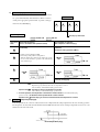
1
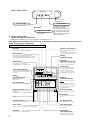
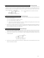
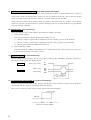
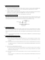
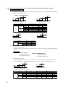
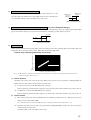
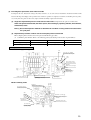
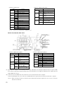
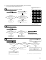
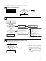
A I R C O N D I T I O N I N G & H E AT P U M P S Y S T E M S
SERVICE GUIDE
Including outdoor unit (FDC 6 Series and 8 Series)
FDT 4-Way Cassette
FDEN Ceiling Suspended
FDKN Wall Mounted
FDR Ducted Cassette
FDU Ducted - High Static
This guide is to assist
site service engineers
with commissioning
of systems and to
provide information
for maintenance and
fault finding.
CONTENTS
Operation
Pages 1 - 15
Wireless Remote Controller
Page 1
Wired Remote Controller
Page 2
Outline of Microcomputer Control Function
Page 3
Operation Control Function by the Wired Remote Controller
Page 11
Operation Control Function by the Outdoor Controller
Page 12
Safety Precautions
Page 16
Maintenance
Pages 17 - 31
Servicing
Page 17
Troubleshooting for Refrigeration Circuit
Page 18
Diagnosing of Microchip Circuit
Page 19
8.4
OUTLINE OF OPERATION CONTROL BY MICROCOMPUTER
(1) Wireless remote controller
Models FDTN (P), FDEN (P), FDKN (P) series
(a)
Remote controller
Signal sender
OPERATION MODE indicator
Signals are sent to the air conditioner
from here.
Indicates selected operation mode
CAUTION
Cooling only air-conditioner has the display of “COOL”, “DRY” and “FAN” only.
Filter reset indicator
Fan speed
The FILTER mark is indicated when the
FILTER RESET button is pressed.
Indicates the selected fan speed
Auto swing
Temperature indicator
Indicates the selection of swing louver.
AUTO COOL DRY FAN HEAT
FAN HI LO
FILTER
°C
Timer ON time
ON AM
PM
Indicates the timer ON time.
When the timer mode is “CONT” or “OFF”,
the present time is indicated.
MODE
OFF AM
PM
TEMP
Set temperature is indicated.
Timer OFF time
Indicated the timer OFF time.
When the timer mode is “CONT” or
“OFF”, there is no indication.
ON/OFF
OPERATION MODE select button
ON/OFF button
This button, whenever pressed, changes the
mode in the following order.
AUTO ➞ COOL ➞ DRY
HEAT FAN
When the button is pressed, the air conditioner
is started, and when the button is pressed once
again, it is stopped. (When the air conditioner
is stopped, the present time only is indicated.
When the air conditioner is operating, details
of setting are indicated.)
➞
FAN SPEED
CAUTION
AIR FLOW
FILTER
Cooling only air-conditioner changes the mode in the following order.
ROOM TEMP. button
FAN SPEED button
Room temperature is set within the
range of 18-30˚C by operating the ∆ ,
∇ or button.
COOL➞DRY➞FAN
TIMER
ACL
Every time when the button is pressed, the
mode is sequentially changed HI →LOW.
SET
TIME
Filter button
Used to reset (turn off) the filter sign.
(Press for more than 1 second.)
Press the button only after completing
the filter cleaning.
Air flow direction button
Used to start or stop the swing louver.
Timer mode button
TIME button
Every time when the button is pressed, the
mode is sequentially changed CONT → ON
→ OFF → PROGRAM.
Used to set the present time and the timer
operation time.
Set button
Reset switch
Used to reset the microcomputer when something is wrong on the remote controller display.
Used to switch from the hour to minute or vice
versa when setting the present time or timer
operation time.
• Above figure shows all indications for the
purpose of explanation, but practically
only the pertinent parts are indicated.
Clock switch
Press this before setting the present time.
(b) Indoor unit indicators
Model FDTN(P) series
Model FDKN (P) series
Remote controller
signal receiver.
RUN LAMP (GREEN)
Light up : Air conditioner is operating.
TIMER/CHECK (YELLOW)
Light up : Timer mode operating.
Flashing : When some error occurs.
1
Model FDEN (P) series
Heavy Duty
RUN CHECK ON/OFF
Remote controller
signal receiver
RUN LAMP (GREEN)
BACK UP SWITCH
When the remote controller is missing or defective, this switch can start
and stop the air conditioner.
Use the back up switch when the battery is exhausted, or when the remote controller is missing or defective.
Usually operate the air conditioner
with remote controller.
Illuminates during operation.
CHECK LAMP (YELLOW)
When a malfunction occurs,
the lamp flashing.
(2) Wired remote controller
Models FDT, FDR, FDU, FDFL series
FDR, FDU and FDFL series are not provided with AUTO SWING switch.
Panel shown below will appear if you open the cover. All contents of display on the LCD are indicated simultaneously for the purpose of explanation.
Pull the knob on the cover to this side to open it downward.
Filter sign
Operation mode display
When this sign is indicated, clean the filter.
Remote display
Displays the operation mode that has
been selected.
(Cooling only air-conditioner has the display
of "COOL" ,"DRY" and "FAN" only.)
This is displayed when the unit is controlled
with an individual controller during normal operation.
(Also displayed when the air conditioner is stopped.)
Heating
preparation display
Central display
Operation/
Inspection indicator lamp
This is displayed when the unit is
controlled with the optional central console.
During operation: Green lamp flashes.
In case of error: Red lamp flashes.
On/Off switch
Timer operation display
Contents of timer operation are displayed.
(Also displayed when the air conditioner
is stopped.)
CENTER REMOTE FILTER
PROGRAM TIMER
ON
Setting
temperature display
OFF
A M
P M
HOT
AUTODRYCOOLFANHEAT HEAT KEEP
SET TEMP
E
°C
FAN
Hi
Mi
Lo
Outdoor No.
°C
Return air
temperature display
Displays the temperature
that has been set.
FILTER
RESET
TIMER
CHECK
SET
TEMP
TIME
Fan speed display
Displays the fan speed that has been set.
Use this switch to start or stop the
air conditioner.First push on the
switch starts the unit and second
push stops it. (The switch can be
operated without opening the cover.)
Filter reset switch
Use this switch to reset (erase) the filter
sign display.
(Press the switch after cleaning the air filter.)
F A N
SPEED
AUTO
SWING
Displays the return air temperature.
MODE
Note
Indicated value may be different
from actual reading on a thermometer
or other instrument but this is not
necessarily an error.
Auto swing display
Indicates the swing louver condition.
Mode switch
Cover
Use this switch to select operation
modes.
Inspection switch
Fan speed switch
Use this switch when servicing the unit.
Use this switch to set a fan speed.
Timer switch
Auto swing switch
Use this switch when selecting contents of timer operation.
Use this switch to operate or stop
the swing louver.
Set switch
Temperature/
Time setting switch
Use this switch to set a time for the timer.
Use this switch to set the room
temperature or time on the timer.
2
(3) Outline of microcomputer control function
(a)
Operation control function by the indoor controller
1)
Automatic operation (Only heat pump type)
If the Auto mode is selected on the remote control device, the selection of cooling or heating can be made automatically
depending on the room temperature (and the temperature of indoor heat exchanger). (When the switching between the
cooling and the heating is made within 3 minutes, the compressor will not operate for 3 minutes.) This will make much
easier the switching of cooling/heating at the change of season and can be adapted to the unmanned operation at bank
cash dispenser.
Cooling operation
Heating operation
Setting room temp.
Room temp. (detected at Th1-A) [deg]
Suspended heating operation
Ready for
heating
Notes (1) During the automatic switching of cooling/heating the
room temperature is controlled based on the setting
of room temperature (DIFF:±}1 deg)
(2) If the temperature of indoor heat exchanger rises beyond 63˚C during the heating operation, it is switched
automatically to the cooling operation. For an hour
after this switching, the heating operation is suspended
regardless of the temperature as shown at left.
Indoor heat exchanger temperature (˚C)
2)
Room temperature control (Differential of thermostat)
Heating operation
Cooling operation
ON (52C)
OFF (52C)
+1
Set temp.by thermostat
-1
3)
OFF (52C)
+1
Set temp.by thermostat
-1
Temperature difference between thermostat set temp.
Temperature difference between thermostat set
and return air temp. (Detected by ThI-A)
temp. and return air temp. (Detected by ThI-A)
Control parts operation during cooling and heating
Function
Control part
Compressor
4-way valve
Outdoor fan
Cooling
Thermostat Thermostat
ON
OFF
×
×
Fan
–
×
Thermostat
ON
Heating
Thermostat
Defrost
OFF
×
×
×
×
×
×
×
×
×
/×
Louver motor
Note(1)
×
×
/×
Indoor fan
Condensate motor
×
Dry
Thermostat Thermostat
HOT START
ON
OFF
×
× (2min. ON) × (2min. ON)
× (2min. ON)
× (2min. ON)
:ON
× :OFF
/ × :According to control other than temperature control.
3
4)
Dehumidifying operation (“THERMAL DRY”)
The compressor, the indoor fan motor and the outdoor fan motor
Operation block
are operated intermittently under thermistor (ThI-A) control according to the appropriate operation block, to provide cooling operation for the dehumidifying.
D
C
B
-2
Low
A
+3
High
Pattern of operation
Set temp. by thermostat
CM, FMO: ON
Operation
block
FMI : ON
Thermal drying starting
(for 8 or 16 minutes after operation started)
Normal thermal dry operation
(after completion of thermal drying)
(16 minutes)
(8 minutes)
Continuous cooling operation (FMI:Lo)
A
B
• Cooling operation (Thermostat ON)
• Indoor fan operating with the setting air flow.
• When the thermostat is turned off, the indoor fan operates
for 30 seconds with the Lo operation in the wind blowing
mode and then stops.
(8 minutes)
CM, FM0
FMI
(8 minutes)
(8 minutes)
CM, FM0
FMI
CM, FM0
FMI
C
D
(8 minutes) All stoppage
Notes (1) Operation block A B : Normal cooling operation for 16 minutes after operation is started.
Operation stops by thermostat when the set temperature is reached.
After 16 minutes, normal thermal drying operation starts.
Operation block C D : Operation as above is performed for 8 minutes.
After 8 minutes, normal thermal drying operation starts.
(2) In normal operation, the temperature is checked at 8 minute intervals after normal thermal drying
operation is started, to determine which operation block is to the selected.
Operation block A thermal drying is carried out if the thermostat set temperature is constant.
5)
Hot spurt (Only heat pump type)
In the hot spurt mode, the control is conducted at the level +2 higher than the setting temperature at the start of heating operation.
The hot spurt is canceled either after the initial thermostat OFF, when the indoor heat exchanger temperature reaches 61˚C or 60
minutes after the start of the mode.
Room temperature (deg)
4
6)
FM control with the heating thermostat turned off (For cold draft prevention) (Only heat pump type)
In order to prevent a cold draft while the heating thermostat is turned off, the indoor blower is controlled in response to the
temperature of the indoor heat exchanger as illustrated below. It should be noted that if SW3-4 on the indoor PCB is turned off, the
indoor blower will stop so far as the temperature of the indoor heat exchanger is lower than 40˚C. It will be turned to the Lo
operation 5 minutes later.
(Setting air flow)
Note (1) After the thermostat is reset, it returns to the hot start
control.
Lo
40
7)
45
Hot start (Cold draft prevention during heating) (Only heat pump type)
1)
If the indoor heat exchanger temperature is lower than 30˚C when the heating operation has started, the following indoor
blower control is performed.
(1)
In case of the thermostat off condition: Lo operation
(2)
In case of the thermostat on condition : Stop
(3)
If the indoor heat exchanger temperature exceeds 30˚C or 7 minutes after the beginning of hot start, the hot start
terminates and it returns to the setting airflow of the blower.
2)
If the indoor heat exchanger temperature is lower than 30˚C when the unit is heating under the thermo-ON condition, the
indoor fan operates in the Lo mode. As the temperature rises higher than 30 ˚C or 7 minutes after the beginning of hot start,
the hot start terminates and it returns to the setting air flow.
8)
Indoor fan control during defrost operation (Only heat pump type)
1)
The indoor fan operation is changed from the setting airflow to the Lo operation 40 seconds before the start of defrost
operation (when the defrost thermostat is turned ON) and stops if the indoor heat exchanger temperature drops below 20˚C.
2)
After the stop as described in 1)-above, the control will be conducted as illustrated below depending on the indoor heat
exchanger temperature.
Lo
Stop
20
30
Indoor heat exchanger temperature(˚C)
3)
If the indoor heat exchanger temperature rises beyond 30˚C of 7 minutes after the end of defrosting, the indoor fan control
related to the defrosting is completed.
5
9)
Condensate pump motor (DM) control (Only FDTN (P), FDT, FDR models)
During the cooling or Dehumidifying operation, the condensate pump motor (DM) is synchronized with the start of compressor
operation. If the operation is switched from the operation stop, error stop, thermostat stop and the cooling of defrosting operation
to the fan or heating operation, the drain motor continues to operate for 2 minutes after the switching.
Overflow detection by means of the float switch is always on regardless of the operation mode. If an overflow occurs (or the float
switch is not connected or the wire is broken), the operation is interrupted as the error stop and the drain motor is operated until the
state of float switch is normalized.
10) Defrost control (FDC 6 series only)
Defrost operation is precisely controlled with the defrost thermostat (23DH1, 2) and a timer.
a)
Defrost starting conditions
Defrost operation will start only when all of following conditions are met.
b)
1)
When the compressor operation time accumulated after the start of heating operation exceeds 30 minutes.
2)
When the compressor operation time accumulated after the end of defrost operation exceeds 45 minutes.
3)
When the defrost thermostat (23DH1) is turned ON (-6˚C)
Defrost terminating condition
If the defrost thermostat (23DH2) is turned OFF (12˚C) or 12 minutes after the start of defrost operation, the defrost operation is canceled and it returns to the heating operation.
11) 4-way valve control (1 phase models only)
In order to maintain the pressure balance after the stop of compressor during cooling, dehumidifying and heating operation. the 4way valve is controlled repeatedly as illustrated below.
Compressor
(During cooling, heating)
ON
OFF
(During cooling)
ON
OFF
ON
OFF
4-way valve
(During heating)
120 sec.
50 sec.
180 sec. or over
12) Frost prevention during cooling (For indoor heat exchanger)
In order to prevent the frosting during cooling operation, the temperature of indoor unit heat exchanger (detected by ThI-R) is
checked 9 min, after the compressor operation start and the unit operation.
This cycle is not operated for 9 min. after the resetting of this frost prevention mechanism.
Cooling operation
OFF (52C)
2.5˚C
10˚C
Indoor heat exchanger (ThI-R)
6
13) Compressor inching prevention control
a)
Compressor 3 minutes delay control
The compressor will remain in stop state for three minutes. When the compressor is stopped by thermostat, ON/OFF switch,
and/or by occurrence of trouble. When the power source is turned ON, the three-minute delay timer is cancelled.
b)
Compressor 3 minutes forced operation control
Compressor cannot be stopped for 3 minutes after it started. However, it will be stopped immediately when the thermostat is
turned off due to the operation stop initiated by the ON/OFF switch or the change of operation mode.
Note (1) Both the error control and the protective control take priority over this control.
14) Overload protection during heating
If an overload condition has been detected by the indoor heat exchanger temperature and it has continued for more than 2 seconds
during heating, the compressor is stopped. The compressor is started after a delay of 3 minutes and, if the overload condition is
detected again whithin 60 minutes after the initial detection, the compressor is stopped with the error stop.
Heating operation
68
61
Indoor heat exchanger
temperature(˚C)
15) Automatic restart control
If there is interruption of power while the unit is operating, the unit operates after power restoration under the same condition as
prior to the power interruption. However the compressor will only be able to start three minutes after the power restoration.
Furthermore, if the timer was operating prior to the power interruption, the unit remains stopped even after the restoration of
service.
Note (1)
Becomes invalid if the dip switch SW3-1 on the indoor PC board is at OFF (SW3-1 is set at ON when unit is shipped
from the factory).
16) Thermistor disconnection detection control
a)
Detection of indoor return air thermistor disconnection
¡ If there is detection of a disconnection on the return air thermistor in 10 seconds after turning the power ON, the compressor is stopped. If there is a second disconnection on the return air thermistor detected within 60 minutes, there is emergency stop.
Note (1) If the first disconnection on the return air thermistor is detected for a period of 6 continuous minutes, there is emergency
stop. If there is no detection of a second disconnection on the return air thermistor whithin 60 minutes, the first detection
becomes invalid.
b)
Detection of heat exchanger thermistor disconnection
¡ If a disconnection is detected on the heat exchanger thermistor in 20 seconds after the compressor has been operating for
2 minutes, the compressor is stopped. If a second disconnection on the heat exchanger thermistor line is detected within
60 minutes, there is emergency stop.
Note (1) If the first disconnection on the heat exchanger thermistor is detected for a period 6 continuous minutes, there is emergency stop.
If there is no detection of second disconnection on the heat exchanger thermistor within 60 minutes, the first detection
becomes invalid.
7
17) Drain detection
a)
(Only FDTN(P), FDT, FDR models)
If there is detection of a drain abnormality during cooling operation, the drain pump goes ON for 5 minutes and the compressor which had been running comes to a stop.
Overflow detection is carried out at all times with the float switch regardless of operational mode. If an overflow is generated
(or if the float switch is not yet connected or has been disconnected). there is emergency stop (while the Check lamp (yellow)
blinks 4 times) the drain motor operates until reset of the float switch.
b)
If a drain abnormality is detected during cooling operation, there is emergency stop (while the Check lamp (yellow) blinks 4
times) to stop the compressor, and the drain pump is operated with the drain motor until reset of the float switch.
c)
If a drain abnormality is detected during a stop state or fan operation, there is forced operation of the drain pump for 5
minutes. After 5 minutes have elapsed, the drain motor stops if the float switch is reset. Otherwise, there is emergency stop
(wile the Check lamp (yellow) blinks 4 times) and the drain motor operates until the float switch is reset.
d)
If the float switch is not connected or if there is a disconnection, there is emergency stop.
18) Low voltage guard control
If the power source voltage remains at a value of 80% of rating or less for 3 continuous minutes during operation of the compressor,
the compressor stops (52C OFF). Furthermore, if the power source voltage remains at a figure of 15% of rating or greater after 3
minutes have elapsed since stopping the compressor, there is restarting of the compressor (52C ON). Moreover, during stoppage of
the compressor, the Run lamp (green) blinks 2 times.
Note (1) When starting the compressor for the first time after turning the operational switch ON, there is starting regardless
of the power source voltage. Furthermore, if dip switch SW 3-2 on the internal substrate is OFF, this becomes
invalid. (Switch SW 3-2 is set to ON upon shipment from the factory).
19) Refrigerant shortage error
When 52C is ON when operating in cooling (including automatic cooling), if heat exchanger sensor temperature for the indoor
unit (ThI -R) does not drop to 25 °C or less for 40 minutes 5 minutes or more after the start of operation, an abnormal stop due to
insufficient refrigerant is performed.
20) External control (remote display)/control of input signal
¡ External control (remote display) output
Following output connectors (CNT) are provided on the control circuit board of indoor unit.
¡ Operation output: Power to engage DC 12V relay (provided by the customer) is outputted during operation.
¡ Heating output: Power to engage DC 12V relay (provided by the customer) is outputted during the heating operation.
¡ Compressor ON output: Power to engage DC 12V relay (provided by the customer) is outputted while the compressor is
operating.
¡ Error output: When any error occurs, the power to engage DC 12V relay (provided by the customer) is outputted.
¡ Control of input signal
(Make sure to connect the standard remote control unit. Control of input signal is not available without the standard remote
control unit.)
Control of input signal (switch input, timer input) connectors (CNT) are provided on the control circuit board of the indoor
unit.
However, when the operation of air conditioner is under the Center Mode, the remote control by CnT is invalid.
8
¡ At shipping from factory [FDTN (P), FDEN (P), FDKN (P) models : J3 (SW5-3), FDT, FDR, FDU, FDFL models : J5 (SW5-2) ]
on PCB OFF]
¡ Input signal to CnT OFF → ON [Edge input] ... Air conditioner ON
¡ Input signal to CnT ON → OFF [Edge input] ... Air conditioner OFF
ON
CnT input
ON
OFF
ON
OFF
OFF
ON
ON
OFF
Unit A
ON
OFF
Remote controller
operation OFF
Remote controller
operation ON
(Last operation has priority.)
¡ When J3 (SW5-3) [FDTN (P), FDEN (P), FDKN (P) models] or J5 (SW5-2) [FDT, FDR, FDU, FDFL models] on the PCB of
indoor unit is turned on at the field.
Input signal to CnT becomes Valid at OFF Æ ON only and the motion of air conditioner [ON/OFF] is inverted.
ON
CnT input
ON
OFF
OFF
ON
ON
Unit A
ON
OFF
OFF
ON
OFF
Remote controller
operation OFF
OFF
Remote controller
operation ON
(Last operation has priority.)
21) Auto Swing Control (Excepted FDR, FDU, FDFL models)
¡ Have a louver motor to move the louvers up and down for the so called “auto swing” function.
¡ The louver auto swing starts when the AUTO SWING key is pressed once and stops when the AUTO SWING key is pressed
again. The louver position is displayed on the LCD on the remote controller. During auto swing, the position displayed on the
LCD changes, but the positions of the louvers and the display are not coordinated. (The louvers swing 3 - 4 times per minute but
the display changes once per second.)
¡ Stopping the louvers
When the AUTO SWING key is pressed to stop the louver movement, the LCD louver-position display stops and the louvers
stop when they come to the position displayed on the LCD. There are four louver stop position on the LCD. (When jumper wire
J7 [FDTN (P), FDEN (P) models] or J3 [FDT model] on the indoor unit printed circuit board is cut, the louvers stop immediately
at the AUTO SWING key is pressed to stop them and the LCD display changes to show this position. (Excepted FDKN (P)
model)
¡ Movement of louver when the power supply to the controller controlling 4 positions of the louver is switched
on. (Only FDT model)
When power supply is switched on, the louver will automatically swing about 2 times (without operating remote controller).
This is an action for the microcomputer to confirm the louver position in order to input the cycle of the louver motor (LM) to the
microcomputer with the limit switch (LS) pushing the louver motor (LM). If the LS action is not input to the microcomputer,
the louver will stop within 1 minute after the power supply is switched on and will not move from then on.
9
¡ Keeping the louvers horizontal during heating (Only heat pump type)
While HOT KEEP is displayed (during hot start operation or when the thermostat has turned off during heating operation), the
louvers stay in the horizontal position to prevent cold drafts, independent of the setting of the AUTO SWING key (auto swing
or stop). The louver position display of LCD displays continuously the original position before this control operation.
When the HOT KEEP display goes out, both the louvers and the LCD display return to their previous position.
(However, after the power supply to the unit is switched on, the louvers swing two times as a check of the power source
frequency, regardless of the settings of the ON / OFF or AUTO SWING keys).
22) Using 1 remote controller to control multiple units (indoor units - up to 16 units) (Only FDT, FDR, FDU, FDFL models)
a)
Function
A single remote control switch can be used for group control of multiple units (indoor units - up to 16 units). All units in the
group that have had the remote control switch set at [Operating Mode] can be turned on and off in order of the unit number.
This functions independently of the thermostat and protection functions of each unit.
Notes (1) The unit number is set by a switch (SW1) on the circuit board for the indoor unit.
Set SW1 : 0~F
Outdoor unit
0
1
2
3
4
Indoor/Outdoor connection wire
F
Refrigerant piping
0
1
2
3
4
F
indoor unit
Remote controller
Remote controller wire
(2) If unit number is not important, random can be used. However, setting in order from 0, 1, 2, to F will ensure setting without error.
b)
Display to remote controller
(i)
Return air temperature, by remote or center and heating preparation: Displays for the youngest unit for the
remote mode (center mode if there is no remote mode) of the units in operation.
(ii)
c)
Inspection and filter sign: Displays either to the first corresponding unit.
Confirmation of connected units
Each push of the inspection switch on the remote control displays the units connected in sequential order from the youngest
unit.
d)
Error
(i)
If an error occurs (protection device activation) with some of the units in the group, those units will have an error stop,
but the properly operating units will continue operation.
(ii) Wiring outline
Route the wire connecting each of the indoor and outdoor units as it would be for each unit. Use the terminal block (X,
Y, Z) for the remote control for the group controller and use a jumper wire among each of the rooms.
10
(b) Operation control function by the wired remote controller
(i)
The following is the sequence of operation for the remote controller operation mode switch.
DRY
(ii)
COOL
FAN
HEAT
AUTO
CPU reset
This functions when the " inspection " and " filter reset switch " on the remote controller are pushed simultaneously. It
operates in the same manner as the power reset.
(iii) Power outage compensation function.
¡ This is enabled by setting dip switch SW3 on the remote control circuit board to ON.
¡ It records the normally used remote control modes. Once power has been restored, it restarts operation by using the
contents of the memory. Note that the stop positions for auto swing and the timer mode are cancelled.
Parts layout on the remote controller PCB
Z
X
Y
WHITE
R18
RED
IC4
IC5
BLACK
R5
R3
IC3
R4
Q3
IC1
R7
R28
Q2
TYPE
R12
R11
R13
Q1
SW1
REMOTE
THERMO
SW2
POWEP OFF
GUARAMTY
DIP switched
(SW1 ~ SW4)
SW3
TEMP DISP.
FAN SPEED
J1
SWING
DISP.
TIMER FUNC.
J2
J4
J3
Jumper wires (J1 ~ J4)
• Function of DIP switched
Switch
SW1
SW2
SW3
ON
OFF
ON
OFF
ON
OFF
• Function of Jumper wires
Function
Cooling only type
Heat pump type
Remote control sensor - Enabled
Remote control sensor - Disabled
Power outage compensation - ON
Power outage compensation - OFF
Switch
J1
J2
J3
J4
Wich
None (1)
Wich
None (1)
Wich
None (1)
Wich
None (1)
Function
Inlet temperature display - Enabled
Inlet temperature display - Disabled
Fan display - 3 speeds
Fan display - 2 speeds
Timer function - Enabled (Normal)
Timer function - Disabled
Auto swing display - ON
Auto swing display - OFF
Note (1) 'None' means that jumper wire is not provided
on the PCB or the connection ic cut.
11
(c) Operation control function by the outdoor controller (Only FDC(P)208~508 type, FDC808, 1008 type)
1) Control for outdoor unit fan
a) Cooling Operation
The speed of the fan for the outdoor unit is controlled by the temperature of the heat exchanger (Tho-R detection) and
the outdoor air temperature (Tho-A).
Models FDC(P)208~508 type
F Zone
C Zone
A Zone
D Zone
B Zone
E Zone
15
18
31
33
Outdoor air temperature (°C)
32
48
57
63
Heat exchanger temperature (°C)
Description of control for fan for outdoor unit
Model
Fan motor
A Zone
Zone
B Zone
C
D
E
C
D
E
Zone
Zone
Zone
Zone
Zone
Zone
F Zone
FDC(P)208~308 type
FM0
Hi
Hi
Hi
Hi
Hi
Lo
Hi
FDC(P)408, 508 type
FM01(Up)
FM02(Lo)
Hi
Hi
Hi
OFF
Hi
OFF
Hi
Hi
Hi
OFF
Lo
OFF
Hi
Hi
Models FDC808, 1008 type
C Zone
A Zone
D Zone
B Zone
44
48
Heat exchanger temperature (°C)
20
25
Outdoor air temperature (°C)
Description of control for fan for outdoor unit
Fan motor
FM01(Left)
A Zone
Hi
Zone
C Zone
Hi
B Zone
D Zone
Lo
b)
FM02(Right)
Hi
OFF
OFF
Heating Operation
1 Stop control for outdoor fan
When the high pressure switch (63H2) operates, the fan for the outdoor unit is stopped to control the high pressure
switch.
63H2 settings
Models FDC208~1008 type
Models FDCP208~508 type
2.5 OFF/2.06 ON (MPa)
2.79 OFF/2.26 ON (MPa)
[25.5 OFF/21 ON (kgf/cm2)]
[28.5 OFF/23 ON (kgf/cm2)]
2 Tap control for outdoor fan
When the high pressure switch (63H2) is closed, the outdoor fan is controlled by the detected heat of the outdoor
heat exchanger thermistor (Tho-R) and the detected heat of the outdoor air temperature thermistor (Tho-A).
E Zone
A Zone
C Zone
D Zone
B Zone
9
11
17
19
Outdoor air temperature (°C)
Description of control for fan for outdoor unit
Model
FDC(P)208~308 type
Fan motor
FM0
Hi
C Zone
A Zone
Hi
D Zone
Zone
Hi
B Zone
C Zone
Lo
E Zone
Hi
D Zone
-3
0
Heat exchanger temperature (°C)
FDC(P)408, 508 type
FM01(Up)
FM02(Lo)
Hi
OFF
Hi
Hi
Hi
Hi
Lo
OFF
Hi
OFF
FDC808,1008 type
FM02(Right)
FM01(Left)
Hi
OFF
Hi
Hi
Hi
Hi
Hi
OFF
Hi
Hi
Note (1) When the fan for the outdoor unit is started when the outdoor air temperature is more than 12 °C, it will operate at high speed for 3
seconds and then switch to low speed. After operating a low speed for 4 minutes, it will be transferred to controlled speed.
12
2)
Control of fan for outdoor unit for de-icing
If DIP switch SW5-2 on the printed circuit board for the outdoor unit is set to on, the
Outdoor fan
operates
at Hi speed
fan on the outdoor unit which has been stopped will operate for 10 seconds at Hi speed
Outdoor fan
stopped
every 10 minutes when the outdoor air temperature is 3 °C or less.
3
5
Outdoor air temperature (°C)
3)
Discharge temperature control during cooling/heating (Only case of FDC(P)208~508 type)
As the discharge gas temperature (detected with ThO-D) rises during cooling/heating operation, the capillary bypass and the liquid
bypass solenoid valve (SV1) are opened so that the abnormal rise of discharge gas temperature is prevented.
SV -open
SV -close
108
115
Discharge gas temp (°C)
Defrost control
Defrost operation will start when the temperature of the heat exchanger for the outdoor unit (Tho-R detection) and the outdoor air
temperature (Tho-A detection) enter the start of defrost range shown in the figure below.
Initiation temp. of defrosting (Detected by Tho-R, Tho-A)
Heat exchanger temperature
4)
-5
-10
-15
tia
Ini
(°C) -20
[Th0-R]
-20
-15
t
ion
p.
em
o
ost
efr
fd
ing
Zone for initiate temp. of defrost
t
-10
-5
0
5
10
Outdoor air temperature (°C) [Th0-A]
Note (1)
If DIP switch SW5-1 on the printed circuit board for the outdoor unit is set to on, defrost operation will begin when temperature of the heat
exchanger for the outdoor unit reaches -7 °C.
a)
Defrost Operation
Switching of the control of the 4-way selector valve during defrost operation can be performed by enabling/disabling the
jumper wire (J17) on the printed circuit board for the outdoor unit.
(i)
J17 None (4-way selector valve ON during heater operation)
Defrost operation is performed with the compressor on, the fan for the outdoor unit off and the 4-way selector valve off.
(ii)
J17 With (4-way selector valve OFF during heater operation)
Defrost operation is performed with the compressor on, the fan for the outdoor unit off and the 4-way selector valve on.
b)
Defrost finished
(i)
Once defrost operation has started, it will finish after the cumulative operating time of the compressor has reached 12
minutes (factory setting: SW5-1 OFF).
Note (1) This time will become 14 minutes if the DIP switch (SW5-1) on the printed circuit board on the outdoor unit is set to on.
(ii)
Switching of the defrost recovery time can be performed by enabling/disabling the jumper wire (J18) on the printed
circuit board for the outdoor unit.
J18 (SW6-2) With: 14 °C, J18 (SW6-2) None: 18 °C
13
5)
Compressor protecting function (Microcomputer and phase protection relay)
a)
Overcurrent control
(i)
When a 52C secondary L1-phase continues for 0.5 seconds and when it is more than the set value (detection at current
sensor CT), the compressor is stopped. The compressor is restarted after a 3-minute delay if the detection current is less
than 1.5 to 2A. If this condition is re-detected 5 times within 60 minutes of the first occurrence, an abnormal stop of the
unit is performed.
(ii)
If 60 minutes passes and the detected current after the first to the fourth stoppage is not less than 1.5~2A, an abnormal
stop of the unit is performed.
b)
Open-phase protection
When a 52C secondary detection current continues for 4 seconds when the compressor is on and when it is less than 1.5 to 2
A, it is determined to be a open-phase of the 52C secondary N-phase, and the compressor is stopped. The compressor is
restarted after a 3-minute delay and if this condition is re-detected within 60 minutes of the first occurrence, an abnormal stop
of the unit is performed.
c)
Detection of abnormal discharge temperature (Only case of FDC(P)208~508 type)
(i)
When an abnormally high temperature is detected at the discharge pipe of the compressor (Tho-D detection), the
compressor is stopped. The compressor is restarted after a 3-minute delay and if this condition is re-detected 5 times
within 60 minutes of the first occurrence, an abnormal stop of the unit is performed.
Operable
Error stop
90
135
Discharge pipe temp. (°C)
(ii)
If 60 minutes passes and the detected temperature after the first to the fourth stoppage is not less than 90 °C, an
abnormal stop of the unit is performed.
Note (1) Once an abnormal discharge temperature has occurred, restarting cannot be performed for 45 minutes. [Detection temperature less than 3 °C]. (In failure mode, resetting cannot be performed by remote control.)
Operation is possible after 45 minutes. (Cleared by resetting power source.)
d)
Cooling overload protection
State of overload during cooling operation is detected (with Tho-R) based on the temperature of outdoor heat exchanger and
the unit operation is stopped / Immediate reset after repair
Operable
Error stop
60°C 70°C
Outdoor heat exchanger temp.
e)
Thermistor [Discharge piping (Only case of FDC(P)208~508 type), Heat exchanger and outdoor air thermistor] disconnected wire
(i) If there is a disconnected wire or if there is a big difference in performance characteristics, an abnormal stop of the unit is
performed. e Restore after repairing.
14
6)
High-pressure protection by high-pressure make-or-break device (63H1)
(Only case of FDCP208~508 and FDC808, 1008 type)
a)
If the pressure rises and 63H1 is operated (opened), the compressor is stopped. After a 3-minute delay, the compressor is
restarted. An abnormal stop is performed when 63H1 is opened five times within 60 minutes of the first operation. e Restore
after repairing.
b)
An abnormal stop is performed at the first occurrence if 63H1 remains open after 60 minutes have passed from the first time
the compressor was stopped.
Note (1) Once 63H1 has been restored after an abnormal stop, the unit can be restarted using the remote control.
7)
Compressor motor protection (Only case of FDC808, 1008 type)
The same detection control as 63H1 will be performed when the internal thermostat 49C operates due to a rise in the windings of
the compressor motor. The setting values of the internal thermostat 49C are 90 °C open and 73 °C close.
8)
Control of the closing and opening of the service valve (Only heat pump type)
a)
When the compressor is ON for the first time after turning on the power, the heating operation starts regardless of any setting.
b)
If the 63H2 turns OFF(open) within 10 seconds after the compressor is ON, the power will turn off as abnormal stop.
c)
To recover from the abnormal stop, turn on the power again after the 63H2 is ON(closed).
d)
If the 63H2 doesn't turn OFF(open) within 10 seconds after the compressor is ON, the operation immediately changes to the
“set mode” to start normal operation.
9)
Test run
a)
For a test run, it is possible to use the dip switches SW5-3 and SW5-4 on the printed circuit board in the outdoor unit.
SW5-3
ON SW5-4
OFF Test run for cooling
ON Test run for heating
OFF Normal
b)
Test run time is 30 minutes. Protective devices are effectively controlled.
15
8.5
APPLICATION DATA
SAFETY PRECAUTIONS
• Please read these “Safety Precautions” first then accurately execute the installation work.
• Though the precautionary points indicated herein are divided under two headings. WARNING and CAUTION , those
points which are related to the strong possibility of an installation done in error resulting in death or serious injury are listed
in the WARNING section. However, there is also a possibility of serious consequences in relationship to the points listed
in the CAUTION section as well.
In either case, important safety related information is indicated, so by all means, properly observe all that is mentioned.
• After completing the installation, along with confirming that no abnormalities were seen from the operation tests, please
explain operating methods as well as maintenance methods to the user (customer) of this equipment, based on the owner’s
manual.
Moreover, ask the customer to keep this sheet together with the owner’s manual.
WARNING
• This system should be applied to places of office, restaurant, residence and the like. Application to inferior
environment such as engineering shop could cause equipment malfunction.
• Please entrust installation to either the company which sold you the equipment or to a professional contractor. Defects from improper installations can be the cause of water leakage, electric shocks and fires.
• Execute the installation accurately, based on following the installation manual. Again, improper installations can result in water leakage, electric shocks and fires.
• When a large air-conditioning system is installed to a small room, it is necessary to have a prior planned
countermeasure for the rare case of a refrigerant leakage, to prevent the exceeding of threshold concentration.
In regards to preparing this countermeasure, consult with the company from which you perchased the
equipment, and make the installation accordingly. In the rare event that a refrigerant leakage and exceeding of threshold concentration does occur, there is the danger of a resultant oxygen deficiency accident.
• For installation, confirm that the installation site can sufficiently support heavy weight. When strength is
insufficient, injury can result from a falling of the unit.
• Execute the prescribed installation construction to prepare for earthquakes and the strong winds of typhoons
and hurricanes, etc. Improper installations can result in accidents due to a violent falling over of the unit.
• For electrical work, please see that a licensed electrician executes the work while following the safety
standards related to electrical equipment, and local regulations as well as the installation instructions, and
that only exclusive use circuits are used.
Insufficient power source circuit capacity and defective installment execution can be the cause of electric
shocks and fires.
• Accurately connect wiring using the proper cable, and insure that the external force of the cable is not
conducted to the terminal connection part, through properly securing it. Improper connection or securing
can result in heat generation or fire.
• Take care that wiring does not rise upward, and accurately install the lid/service panel. Its improper installation can also result in heat generation or fire.
• When setting up or moving the location of the air-conditioner, do not mix air etc. or anything other than the
designated refrigerant (R22) within the refrigeration cycle.
Rupture and injury caused by abnormal high pressure can result from such mixing.
• Always use accessory parts and authorized parts for installation construction. Using parts not authorized
by this company can result in water leakage, electric shock, fire and refrigerant leakage.
CAUTION
• Execute proper grounding. Do not connect the ground wire to a gas pipe, water pipe, lightning rod or a
telephone ground wire. Improper placement of ground wires can result in electric shock.
• The installation of an earth leakage breaker is necessary depending on the established location of the unit.
Not installing an earth leakage breaker may result in electric shock.
• Do not install the unit where there is a concern about leakage of combustible gas.
The rare event of leaked gas collecting around the unit could result in an outbreak of fire.
• For the drain pipe, follow the installation manual to insure that it allows proper drainage and thermally
insulate it to prevent condensation. Inadequate plumbing can result in water leakage and water damage to
interior items.
16
8.6
MAINTENANCE DATA
8.6.1
Servicing
(1) Evacuation
The evacuation is a procedure to purge impurities, such as noncondensable gas, air, moisture from the refrigerant equipment by
using a vacuum pump. Since the refrigerant R22 and R407C is very insoluble in water, even a small amount of moisture left in the
refrigerant equipment will freeze, causing what is called ice clogging.
Evacuation procedure
Make sure that the both service valves of gas and liquid line are fully opened.
(a)
Check to ensure that there is no internal pressure in the unit. If there is an internal pres-
Indoor unit
Outdoor unit
sure, it should be relived through the service
port.
(b)
Liquid line
Connect the charging hose of the gauge manifold to the service port of the gas piping.
Gas line
service port
Close high pressure valve 2 of gange manifold.
(c)
Flare connection
Connect the charging hose A to a vecuum
pump.
Repeat evacuation in the following sequence.
Service hoses
1
Charging hose
2
Gauge
manifold
A
3
Start the vacuum pump.
h
Compond pressure gauge indicates -0.1 MPa (-76 cmHg)
h
Operate the vacuum pump for more than 10 minutes after -0.1MPa
(-76 cmHg) Hg is indicated.
h
Close low pressure valves 1 of gauge manifold.
h
Stop the vacuum pump.
Notes (1) Do not use the refrigerant pressure to expel air.
(2) Do not use the compressor for evacuation.
(3) Do not operate the compressor in a vacuum condition.
17
Lo Hi
Vacuum
pump
Refrigerant
cylinder
Notes (1) Refer to the exterior-view drawing for the position
of the service valve.
(2) When connecting of the service valve, flare connection for both the indoor and outdoor unit.
(2) Refrigerant charging
(a)
After the evacuation shown in the above, change the connection of the charge hose A to the refrigerant cylinder.
(b)
Purge air from the charge hose A .
First loosen the connecting portion of the charge hose at the gauge manifold side and open valve 3 for a few seconds, and
then immediately retighten it after observing that gas has blown out from loosened connecting portion.
(c)
Open valves 1 and 3 then gas refrigerant begins flowing from the cylinder into the unit.
When refrigerant has been charged into the unit to some extent, refrigerant flow becomes stagnant. When that happens, start
the compressor in cooling cycle until the system is filled with the specified amount of gas, then close valves 1 and 3 and
remove the gauge manifold. Cover the service port with caps and tighten them securely.
(d)
Check for gas leakage by applying a gas leak detector around the piping connection.
(e)
Start the air conditioner and make sure of its operating condition.
8.6.2
Trouble shooting for refrigerant circuit
(1) Judgement of operating condition by operation pressure and temperature difference
Making an accurate judgement requires a skill that is acquired only after years of experience, one trouble may lead to an another
trouble from a single trouble source and several other troubles may exist at the same time which comes from a undetected different
trouble source.
Filtering out the trouble sources can be done easier by comparing with daily operating conditions. Some good guides are to judge
the operating pressure and the temperature difference between suction air and delivery air.
Following are some pointers,
High side
Low side
High side
Low side
High side
Low side
High side
Low side
High side
Low side
Too high
A little
high
Normal
A little low
Circuit
Too low
Pressure
Indication
¡
¡
¡
¡
¡
¡
¡
¡
¡
¡
Trouble cause
1) Excessive overcharging of refrigerant
2) Mixture of non condensable gas (air etc.)
Ineffective compression
(defective compressor)
1) Insufficient refrigerant in circuit
2) Clogging of strainer
3) Gas leakage
4) Clogging of air filter (in cooling)
5) Decrease in heat load (in cooling)
6) Locking of indoor fan (in cooling)
1) Locking of outdoor unit fan (in cooling)
2) Dirty outdoor heat exchanger (in cooling)
3) Mixture of non condensable gas (air etc.)
1) Too high temperature of room
18
8.6.3
Diagnosing of microcomputer circuit
(1) Selfdiagnosis function
(a)
Indoor unit side
(i)
Only case of wireless remote control model.
Check indicator table
Failure mode on the indoor unit indicated by flashing Yellow LED and Green LED.
Indoor unit LED
Yellow
Green
1 time flash
–
2 time flashes
–
4 time flashes
–
Failure at:
Contents of the failure
Indoor unit heat exchanger
thermistor
Indoor unit circuit board
Indoor unit air return thermistor
Indoor unit circuit board
Failure in drainage
Float switch
Indoor circuit board
5 time flashes
–
6 time flashes
–
–
Insufficient refrigerant
Indoor unit heat exchanger thermistor
Indoor unit circuit board
Installation and operating conditions
Indoor unit heat exchanger thermistor
Indoor unit circuit board
• When the power source voltage is 80% of rating or lower.
2 time flashes Low voltage protection
Note (1)
• Indoor unit heat exchanger thermistor defective (element defective or broken wire).
Defective connection of connector for thermistor.
• Indoor unit circuit board defective (defective thermistor input circuit)?
• Indoor unit return thermistor defective (element defective or broken wire).
Defective connection of connector for thermistor.
• Indoor unit circuit board defective (defective thermistor input circuit)?
• Failure with the condensate pump (DM), or open circuit or disconnection of connector with the condensate pump.
• Malfunctioning of the float switch (erroneous functioning)
• Indoor unit circuit board defective (defective float switch input circuit)
• Indoor unit circuit board defective (defective DM driving output circuit)
• Gas leak.
• Indoor unit heat exchanger thermistor defective (short circuit).
• Indoor unit circuit board defective (defective thermistor input circuit)?
• Heating overload (temperature of heat exchanger for indoor unit abnormally high)
• Indoor unit heat exchanger thermistor defective (short circuit)?
• Indoor unit circuit board defective (defective thermistor input circuit)?
Inspection LED display has a cycle of 8 seconds (flashing time of 0.5 seconds).
(ii) Only case of wired remote control model.
Table of inspection items based on error codes
Error Code
E1
E6
E7
E8
E9
Failure at:
Operating switch wire
(signal noise)
Circuit board for operating
switch or indoor unit
Indoor unit heat exchanger
thermistor
Indoor unit circuit board
Indoor unit circuit board
• Indoor unit return thermistor defective (element defective or broken wire). Defective connection
of connector for thermistor.
• Indoor unit circuit board defective (defective thermistor input circuit)?
Installation and operating conditions
• Heating overload (temperature of heat exchanger for indoor unit abnormally high)
Indoor unit heat exchanger thermistor
• Indoor unit heat exchanger thermistor defective (short circuit).
Indoor unit circuit board
• Indoor unit circuit board defective (defective thermistor input circuit)?
Failure in drainage
• Failure with the condensate pump (DM), or open circuit or disconnection of connector with the condensate pump.
Float switch
• Malfunctioning of the float switch (erroneous functioning)
Indoor unit air inlet thermistor
• Indoor unit circuit board defective (defective float switch input circuit)
Indoor circuit board
E10
E57
19
Contents of the failure
• Defective connection or broken wire for operating switch signal wire.
• Signal noise has entered the operating switch wire.
• Is the circuit board for the operating switch or the circuit board for the indoor unit is defective
(communication circuit defective)?
• Indoor unit heat exchanger thermistor defective (element defective or broken wire). Defective
connection of connector for thermistor.
• Indoor unit circuit board defective (defective thermistor input circuit)?
• Indoor unit circuit board defective (defective DM driving output circuit)
Number of indoor units connected
• 1 Remote controller for multiple unit control, 17 or more indoor units connected
Insufficient refrigerant
• Gas leak.
Indoor unit heat exchanger thermistor
• Indoor unit heat exchanger thermistor defective (short circuit).
Indoor unit circuit board
• Indoor unit circuit board defective (defective thermistor input circuit)?
(3) Error diagnosis procedures at the indoor unit side
To diagnose the error, measure the voltage (AC, DC), resistance, etc. at each connector around the circuit board of indoor unit
based on the inspection display or the operation state of unit (no operation of compressor or blower, no switching of 4-way valve,
etc.). If any defective parts are discovered, replace with the assembly of parts as shown below.
(a)
Single-unit replacement parts for circuit board of indoor unit. (Peripheral electric parts for circuit board.)
Indoor unit printed circuit board, thermistor (return, heat exchanger), operating switches, limit switches,
transformers, fuses.
Note (1) Use normal inspection methods to determine the condition of strong electrical circuits and frozen cycle parts.
(b) Replacement procedure of indoor unit microcomputer printed circuit board
Microcomputer printed circuit board can be replaced with following procedure.
(i)
Confirm the parts numbers. (Refer to the following parts layout drawing for the location of parts number.)
Model
FDKN(P)258, 308
FDT, FDR, FDU, FDFL
Parts number
PJA505A069
PHA505A007
Model
FDTN(P), FDEN(P)
FDKN(P)208
Parts number
PHA505A008
PJA505A092Z
Parts layout on the indoor unit PCB
Models: FDTN (P), FDEN (P) series
SW3
SW2 (Only case of FDTN)
(Optional : For auto lift panel)
9
7
6
3
4
8
SW4
13
SW2
CNE
11
SW3
10
For test mode selection
(Shortcircuit : Test mode)
SW4
52X6
52X5
52X4
52X7
52X1
52X2
52X3
Thermistor
(Return air, heat exchanger)
CNN
SW5
SW5
Power
supply
CNL
Receiving unit
Backup switch
Indiction lamps
(
1
CNV
Transformer, primary side
)
CNT
Transformer, secondary side
External input /
output function
supply connector
( Power
)
for PCB
Model: FDKN (P) series
Thermistor
(Return air, heat exchanger)
For test mode selection
(Shortcircuit : Test mode)
SW5
SW3
Transformer, secondary side
Power supply connector
for PCB
(
SW4
)
External input /
output function
Transformer, primary side
Receiving unit
switch
( Backup
Indiction lamps )
Power
supply
20
• Function of jumper wires
Name
J1(SW5-1)
J2(SW5-2)
J3(SW5-3)
J4(SW4-1)
J5(SW4-2)
J6(SW4-3)
J7(SW4-4)
*1
J7(SW4-4)
• Function of DIP switched (SW3)
Function
1 Phase model
3 Phase model
Cooling only type
Heat pump type
Pulse input
Step input
With
None
With
None
With
None
With
None
With
None
With
None
With
None
With
None
Switch
ON
OFF
ON
SW3-1
SW3-2
OFF
ON
OFF
ON
SW3-3
—
Antifrost 2.5˚C
Antifrost 1˚C
With abnormality resetting
Without abnormality resetting
4 position louver control: valid
4 position louver control: invalid
FDKN208 type
FDKN258, 308 type
SW3-4
OFF
Function
Power off guaranteed
No power off guaranteed
With low-voltage detection
control
Without low-voltage detection
control
Power up mode (UHi-Lo)
Mild mode (Hi-Lo)
Indoor fan is Lo when heating
thermostat is OFF.
Indoor fan is OFF when
heating thermostat is OFF.
Note (1) *1 J7 (SW4-4) is for switching models on the FDKN (P) Series.
Model: FDT, FDR, FDU, FDFL series
SW4
9
7
6
3
4
8
SW2 (Only case of FDT)
(Optional : For auto lift panel)
SW3
13
11
SW2
SW3
SW4
10
SW1
SW5
52X6
CNQCNS
52X5 52X4 52X7 52X1 52X2 52X3
CNV
Transformer, primary side
Transformer, secondary side
supply connector
( Power
)
for PCB
• Function of DIP switched (SW3)
Switch
SW3-1
SW3-2
SW3-3
SW3-4
ON
OFF
ON
OFF
ON
OFF
ON
OFF
Function
Power off guaranteed
No power off guaranteed
With low-voltage detection
control
Without low-voltage detection
control
Power up mode (UHi-Lo)
Mild mode (Hi-Lo)
Indoor fan is Lo when heating
thermostat is OFF.
Indoor fan is OFF when
heating thermostat is OFF.
CNH CNN
CNE
Power
supply
CNT
SW1
unit number
( Indoor
)
address switch
SW5
For test mode selection
(Shortcircuit : Test mode)
Thermistor
(Return air)
Thermistor
(Heat exchanger)
External input /
output function
• Function of DIP switched (SW4, 5)
Switch
SW4-1(J1)
SW4-2(J2)
SW4-3(J3)
SW5-1(J4)
SW5-2(J5)
ON
OFF
ON
OFF
ON
OFF
ON
OFF
ON
OFF
Function
Antifrost 2.5˚C
Antifrost 1˚C
With abnormality resetting
Without abnormality resetting
4 position louver control: valid
4 position louver control: invalid
1 Phase model
3 Phase model
Step input
Pulse input
(ii) Please match the settings of control switching switches (SW3, SW4, SW5) to the settings they had before they were replaced. With
these switches, if the printed circuit had a jumper wire before being replaced, set to jumper wire ON if there was a jumper wire and
jumper OFF is these was not.
(iii) Connect the fast-on terminals and connectors that are to the circuit board for the micro-computer.
Connect by matching the wire color of the fast-on terminal with the color printed on the circuit board for the micro-computer.
Note (1) When connecting to the fast-on connection for the circuit board for the micro-computer, use care so as not to excessively
distort the circuit board.
21
(c) Inspection method when there are fault lamps (display lamps on indoor unit).
(i)
Return air thermistor (ThI-A)
Indoor unit heat exchanger thermistor
(ThI-R)
Resistance temperature characteristics
Defective indoor unit heat exchanger thermistor
Indoor unit
Check Lamp (yellow)
Defective indoor unit PCB Replacement (Defective indoor unit heat
exchanger thermistor input circuit)
1 time flash
15
Resistance (kΩ)
1
Only case of wireless remote control model
YES
Is the indoor
unit heat exchanger
thermistor connector
connection OK?
Are characteristics
of indoor unit heat
exchanger thermistor OK
or is not there any
broken wire?
YES
10
5kΩ at 25˚C
5
NO
NO
Defective indoor unit heat exchanger
thermistor Replacement
Correction
0
10
20
30
40
50
Temperature (˚C)
Note (1) 22.5 kΩ at -6˚C
2
Defective return air thermistor
Indoor unit
Check Lamp (yellow)
2 time flashes
Is the return air
thermistor connector
connection OK?
Is the return air
thermistor characteristics
OK or is there a
broken wire?
YES
NO
NO
Note (1) Characteristics as per the above graph.
Defective return air
thermistor Replacement
Correction
3
Defective indoor unit PCB
Replacement (Defective return air
thermistor input circuit)
YES
Drain abnormality
Defective indoor unit PCB
Replacement (Defective condensate motor output
circuit)
Indoor unit
Check Lamp (yellow)
4 time flashes
NO
(1)
Is there any
overflow?
YES
Is the angle of
drain piping good. Is there
any problem?
NO
Is the float
switch tripper?
YES
Repair
YES
Repair or replace the
float switch
Is there output
for condensate motor
(DM)?
YES
¡Check DM broken wire, burning, locking.
¡Are there any DM connector loose.
¡Are there any PCB faston terminal loose.
¡Are there any DM wire broken.
NO
Defective indoor unit PCB Replacement (Defective DM driving output circuit, defective float switch input circuit)
Note (1) Check if power source is there between DM connectors.
22
4
Abnormality casued by insufficient refrigerant.
Are the
characteristic values for
the heat exchanger
thermistor OK?
Indoor unit
Check Lamp (yellow)
5 time flashes
NO
Replace heat exchanger thermistor.
YES
Is the
amount of refrigerant
circulation good? (If refrigerant is insufficient, the capillary tubes may be
plugged.)
NO
Charge with refrigerant.
Replace capillary tubes.
YES
Note (1) Refer to previous page for heat exchanger thermistor temperature resistance characteristic values.
5
Printed circuit board for indoor
unit no good
replace.
Heating overload
Indoor unit
Check Lamp (yellow)
6 time flashes
Note (1) To see whether or not it is overloaded, check the following:
YES
Is the air filter
clogged?
(
Washing
NO
Is the indoor
unit heat exchanger
thermistor connector
connection OK?
YES
Are the heat
exchanger thermistor
characteristics OK, is
there no short
circuit?
NO
uIs the inside/outside air temperature too high?
uIs there any short circuit?
uIs the refrigerant excessive?
(1)
YES
Is the heating
under overload?
YES
Adjustment
NO
NO
Defective heat exchanger
thermistor Replacement
Correction
)
Defective indoor unit PCB
Replacement (Defective indoor unit heat
exchanger thermistor input circuit)
(ii) Only case of wired remote control model
1
Error display :
e1
[Communication error between control switch ~ Indoor unit PCB]
• Normal voltage for control switch wiring (DC)
Between X and Z : 10.5 ~ 10.8 V
Between Y and Z : 5 ~ 10.8 V
Is there
DC 10.8V
between control
YES
switch circuit board connector (CnB) X
(Red) to Z
(Black)?
NO
Is there
DC 10.8V
between indoor unit
PCB connector (CNB)
1 (Red) to 3
(Black)?
Does the
voltage oscillate
between DC6 and 10V
between control switch
circuit board connector
(CnB) Y (White)
to Z (Black)?
NO
Defective control
switch PCB
YES
23
YES
YES
Does the
voltage oscillate
between DC6 and
10V between indoor unit
PCB connector (CNB)
2 (White) to 3
(Black)?
YES
NO
The control switch wiring
(white) or (black) is broken or
have a defective connection.
Power
supply
reset
Is it
normalized?
NO
(1)
Defective control switch
PCB Replacement
Defective indoor unit PCB
Replacement
Note (1) If it is normalized by changing PCB, judge the control switch or indoor
unit PCB (Communication error between control switch and unit) is
detective.
NO
Defective indoor
unit PCB
Unit is normal
(Intrusion of accidental
noise on the control switch
cord)
The control switch wiring (red)
or (black) is broken or have a
defective connection.
2
e6
Error display :
[Defective indoor unit heat exchanger thermistor]
Return air thermistor (ThI-A)
Indoor unit heat exchanger thermistor
(ThI-R)
Resistance temperature characteristics
Defective indoor unit PCB Replacement (Defective indoor unit heat
exchanger thermistor input circuit)
Resistance (kΩ)
15
YES
Is the indoor
unit heat exchanger
thermistor connector
connection OK?
Are characteristics
of indoor unit heat
exchanger thermistor OK
or is not there any
broken wire?
YES
10
5kΩ at 25˚C
5
NO
NO
Defective indoor unit heat exchanger
thermistor Replacement
Correction
0
10
20
30
40
50
Temperature (˚C)
Note (1) 22.5 kΩ at -6˚C
3
e7
Error display :
[Defective return air thermistor]
Is the return air
thermistor connector
connection OK?
Is the return air
thermistor characteristics
OK or is there a
broken wire?
YES
NO
NO
Defective return air
thermistor Replacement
Correction
4
Error display :
e8
Is the air filter
clogged?
Defective indoor unit PCB
Replacement (Defective return air
thermistor input circuit)
YES
Note (1) Characteristics as per the above
graph.
[Heating overload]
YES
Washing
NO
Is the indoor
unit heat exchanger
thermistor connector
connection OK?
NO
Correction
YES
Are the heat
exchanger thermistor
characteristics OK, is
there no short
circuit?
(1)
YES
Adjustment
NO
NO
Defective heat exchanger
thermistor Replacement
YES
Is the heating
under overload?
Defective indoor unit PCB
Replacement (Defective indoor unit heat
exchanger thermistor input circuit)
Note (1) To see whether or not it is overloaded, check the following:
(
s Is the inside/outside air
temperature too high?
sIs there any short circuit?
sIs the refrigerant excessive?
)
24
5
e9
Error display :
[Failure in drainage]
Defective indoor unit PCB
Replacement (Defective condensate motor output
circuit)
NO
(1)
YES
Is there any
overflow?
Is the angle of
drain piping good. Is there
any problem?
NO
YES
Is there output
for condensate motor
(DM)?
Repair
YES
Is the float
switch tripped?
Repair or replace the
float switch
YES
¡Check DM broken wire, burning, locking.
¡Are there any DM connector loose.
¡Are there any PCB faston terminal loose.
¡Are there any DM wire broken.
NO
Defective indoor unit PCB Replacement (Defective DM driving output circuit, defective float switch input circuit)
6
Error display :
e 10
Are
17 or more unites
connected to 1 remote
controller?
Note (1) Check if power source is there between DM connectors.
[1 Remote controller for multiple unit control
units or more)]
YES
Exceeding connected units (17
Change to 16 units or less.
NO
Remote controller defective
Replace
7
Error display :
e 57
[Insufficient refrigerant]
Inspect at the unit side.
(1)
Are the
heat exchanger
YES Insufficient refrigerant
thermistor characteristic
normal?
NO
Inspect at the unit side.
Recharge with (weighed amount)
of refrigerant.
During cooling
• Is indoor fan operating?
• Is the service valve (gas and
liquid side) opened fully?
• Is there no short circuit?
Defective heat exchanger
thermistor Replacement
Is the unit
normalized?
NO
Defective indoor unit PCB
Replacement (Defective
indoor unit heat exchanger
thermistor input circuit)
25
Note (1) Refer to previous page for heat exchanger thermistor heat resistance
characteristic values.
(4) Outdoor unit side (FDC(P)208~508 type, FDC808, 1008 type)
Check Indicator Table
Failure mode on the outdoor unit is indicated by flashing both Green LED (LED-G) and Red LED (LED-R) on the printed circuit board.
Outdoor unit LED
Failure at:
Green
Red
Keeps flashing
Stays OFF
Stays OFF
1 time flash
Stays OFF
Stays OFF
Stays OFF
Stays OFF
Contents of the failure
Normal/Power is supplied.
Power wiring
• The outdoor power wiring is in reversed phase.
• Open phase at L3 phase (primary side).
• Incorrect set-up of outdoor unit PCB.
2 time flashes
Installation or
operation status
• Over current of the compressor motor.
• Open phase at L2 phase (secondary wiring of 52C) of compressor.
• Defective outdoor unit PCB.
3 time flashes
CM wiring
• The wiring (secondary wiring of 52C) to the compressor is open.
Installation or
operation status
• The outdoor heat exchanger temperature is too high [70°C or over].
Outdoor heat
exchanger thermistor
• Failure with the outdoor heat exchanger thermistor.
Installation or
operation status
• The discharge gas temperature is too high.
Discharge gas
thermistor
• Failure with the discharge gas thermistor.
4 time flashes
5 time flashes
1 time flash
1 time flash
Outdoor heat
exchanger thermistor
• Failure or open circuit with the outdoor heat exchanger thermistor or
imperfect connection of the connector.
1 time flash
2 time flashes
Outdoor temperature
thermistor
• Failure or open circuit with the outdoor temperature thermistor or
imperfect connection of the connector.
1 time flash
3 time flashes
Discharge gas
thermistor
• Failure with the discharge gas thermistor or imperfect connection of the
connector.
1 time flash
4 time flashes
Installation or
operation status
• The high pressure is too high or it went up (63H1, 49C).
1 time flash
5 time flashes
Failure to open the
service valve
• Closing of the service valve on the liquid/gas side.
“Check Indicator” is resetted when power supply is turned off once and the failure is fixed.
Procedure for diagnosing trouble for outdoor unit
When diagnosing trouble for the outdoor unit, check the flashing and turns of the inspection indicator lamp (red LED) and
fault indicator lamp (green LED) to obtain a general concept of the nature of the problem. Then inspect and perform repair.
1)
Unit replacement parts related to printed circuit board for outdoor unit.
Micro-computer for outdoor unit, microcomputer, printed circuit board, thermistor (heat exchanger, discharge piping
and outdoor air), fuses and transformer.
Summary of replacement for micro-computer for outdoor unit
a) Check the following part number
Model
1 phase model
Parts No.
Model
PCA505A046ZN
3 phase model
Parts No.
Model
Parts No.
PCA505A046ZS
FDC808, 1008 model
PCA505A046ZC
b) Set the overcurrent value using the overcurrent setting switch (SW3) for CM. Refer to the following table at the setting.
• Table of switch (SW3) setting
FDC208HEN3A FDC258HEN3A FDC308HEN3 FDC308HES3 FDC408HES3 FDC508HES3
FDC808HES3 FDC1008HES3
FDCP208HEN3A FDCP258HEN3A FDCP308HEN3 FDCP308HES3 FDCP408HES3 FDCP508HES3
6
4
3
2
1
ON
1
ON
2
3
4
5
6
34
5
6
1
ON
2
3
4
5
6
5
3
1
ON
2
3
2
1
ON
24
15
4
5
6
12
4
5
4
1
ON
2
3
4
3
2
1
9
6
23
5
6
5
4
3
2
Table of switch
setting
Make ON/OFF
setting for each
switch No.
( : ON, : OFF)
15
6
12
Setting value (A)
ON
Model
1
2)
ON
(a)
26
PCB power supply connector
Parts layout on the outdoor unit PCB
(Primary side)
63H1
63H1
63H2
Inspection display lamp
(LED·Red)
63H2
CNR
PCB power supply connector
52C
CF2
CF2
CF1
CF1
52C
SV
20S
SV
SV2
X03
CNF
(Secondary side)
X02
X07
(LED·Green)
SV2
X05
X08
CNA2
X09
LED-R
LED-D
Inspection display lamp
20S
X01
F1
R3
R4
R1
R2
R5
R6
R7
R8
R11
R3
R12
R10
CNA1
X04
SW3
CNL
SW4
OFF
2
(J4)
OFF
ON
1
(J17)
OFF
2
(J18)
OFF
3
(J19)
OFF
4
(J20)
OFF
27
ON
ON
ON
SW6
SW4
SW5
1
1
2
2
3
3
4
4
J3
J4
J5
J9
1
2
3
4
SW5
3
OFF
ON
ON
OFF
1
3 Phase model
OFF
–
ON
(J5)
ON
ON
Compressor Rotary
unit
Reciprocal
switching
Scroll
2
OFF
Spare
3
OFF
4
Defrost Circulation
Temperature Switching
Defrost Switching
Snow protection control
Actual spot
Ordinary
Enabled
Disabled
Test run
Test run Switch
Normal
Test run for heating
Test run for cooling
OFF
• Function of jumper wire
Function
4-Way Valve Control
Function
ON
ON
• Function of DIP switched (SW6)
SW6
SW5
• Function of DIP switched (SW5)
1 Phase model
OFF
4 (J9)
SW4
Function
ON
1 (J3)
ON
CT1
CNQ
SW6
• Function of DIP switched (SW4)
J17
J18
J19
J20
SW3
1
2
3
4
5
6
CNE
Name
Enabled
Disabled
14˚C
18˚C
Enabled
63HI Abnormal
detection switching
Disabled
3 minute delay when power
is turned on Switching
Disabled
Enabled
With
J21
None
Function
Service valve open/close check control enabled.
Service valve open/close check control disabled.
(b) Inspection method when there are fault lamps (outdoor unit LED)
1
Open phase at L3 phase (Primary side)
Outdoor unit
Red LED
1 time flash
Green LED
Stays OFF
Is L3 phase at
primary side at open
phase
YES
Correction
NO
Defective outdoor unit PCB
Replacement
2
Overcurrent of the compressor motor
Outdoor unit
Red LED
2 time flashes
Green LED
Stays OFF
Power supply
checked at L1 - L2 , L1 - L3
or L2 - L3 phase of 52C
secondary side?
NO
YES
(1)
Compressor
overcurrent?
YES
NO
• 3 Phase: Open phase at
or L2 phase
L1
• Is the power supply voltage correct
(not too low)?
• Are the power supply wires appropriate (not too thin)?
• Is the overcurrent setting correct
(SW3 setting)?
• Is not it operated under overload?
Defective outdoor unit PCB
Replacement (Defective
CT input circuit)
• Defective 52C
• 3 phase: Broken wire at L1 or L2
phase between 52C ~ CM or
TB1 ~ 52C
Inspect at the unit side.
• During cooling: Is FM0 operating?
• At heating:
Is FM1 operating?
Is the service valve (gas side) opened
fully?
Is the filter clogged?
• Is it overcharged?
• Is the installation space of indoor
outdoor unit adequate?
• Is there any short circuit on the indoor/
outdoor unit?
Note (1) Measure and check the current value.
Confirm that the overcurrent setting by SW3 of outdoor
unit PCB is correct.
3
The wiring (secondary wiring of 52C) to the compressor is open.
Outdoor unit
Red LED
3 time flashes
Green LED
Stays OFF
(1)
YES
52C secondary side
or L3 phase open?
L2
NO
(2)
Defective outdoor unit PCB
Replacement
(Defective CT circuit)
Repair
Notes (1) When voltage is detected at 52C primary side L2 or L3
phase but not at the secondary side, check also 52C (broken coil, poor contact).
(2) When voltage is detected at 52C primary side L2 or L3
phase and there is no error at 52C (52C is energized if TB1
L2 or L3 terminal and 52C coil secondary side connector
are short circuited), the outdoor unit PCB (defective X01
circuit or X01 ) or indoor unit PCB (defective thermostat
circuit) is defective.
28
4
The outdoor heat exchanger temperature is too high (70°C or over)
(1)
Are the heat
exchanger thermistor
Charateristisc
Normal?
Outdoor unit
Red LED
4 time flashes
Green LED
Stays OFF
Check the unit side closely
(1)
YES
Cooling, overload
operation?
NO
Heart exchanger thermistor
replacement
• Is outdoor fan motor operating?
• Is the outdoor unit shortcircuited?
• Is the installation space adequate?
• Is there too much refrigerant?
Note (1) Outdoor unit heat exchanger thermistor detects
the state of cooling overload operation.
Is the unit
normalized
Error stop
Reset
NO
Defective outdoor unit
PCB
Replacement
(Defective heat exchanger
thermistor input circuit)
5
60°C
70°C
Outdoor unit heat exchanger temperature
The discharge gas temperature is too high. (Only case of FDC(P)208~508 type)
Outdoor unit
Red LED
5 time flashes
Green LED
Stays OFF
Is the
discharge gas thermistror characteristics
normal?
YES
Discharge gas
temperature error?
(At cooling/heating
operation)
Check the unit side.
NO
Discharge pipe thermistor replacement
Is the unit
normalized
• During cooling: Is FMo operating?
• During heating: Is FMI operating?
Are control valves (both liquid,
gas) fully opened during both
cooling and heating.
• Is the installation space of indoor/
outdoor units adequate?
• Is there any short circuit air flow
for indoor/outdoor units?
Error stop
Operable
NO
Defective outdoor unit
PCB
Replacement
(Defective discharge gas
thermistor input circuit)
6
Check the unit side.
• Insufficient refrigerant
Charge the refrigerant (measure)
• Is it the overload operation?
90°C 135°C
Discharge pipe temp.
Defective outdoor unit heat exchanger thermistor
Outdoor unit
Red LED
1 time flash
Green LED
1 time flash
Outdoor unit heat exchanger
thermistor (ThO-R) Resistance
temperature characteristics
15
Is the outdoor
unit heat exchanger
themistor connector
OK?
YES
Are the outdoor
unit heat exchanger themistor
characteristics OK, is there
any broken wire?
Defective outdoor unit PCB
YES
Replacement (Defective
outdoor unit heat exchanger
thermistorinput circuit)
NO
Repair
NO
Defective outdoor unit
heat exchanger thermistor
Replacement
Resistance (kΩ)
10
5
5kΩ at 25°C
0°C 10°C 20°C 30°C 40°C 50°C
Temperature
Note (1) 22kΩ at -6°C
29
7
Defective outdoor temperature thermistor
Outdoor unit
Red LED
2 time flashes
1 time flash
Is the outdoor
air temperature thermistor
connector connection
OK?
YES
Is the outdoor
temperature thermistor
characteristics OK, is there
no broken wire?
Defective outdoor unit PCB
Replacement (Defective outdoor
temperature thermistor input
circuit)
YES
Temperature-resistance
characteristics of outdoor
temperature thermistor (ThO-A)
NO
NO
Defective outdoor temperature thermistor
Replacement
<0]
Thermistor resistance (kΩ)[T=
Repair
400
40
300
30
200
>0]
Thermistor resistance (kΩ)[T=
Green LED
20
< 0°C
T=
> 0°C
T=
100
10
0
–50°C
0°C
50°C
0
Temperature [T]
Defective discharge gas thermistor (Only case of FDC(P)208~508 type)
Outdoor unit
3 time flashes
Green LED
Is the
discharge gas thermistor
connector connection
OK?
NO
Repair
1 time flash
YES
Are the discharge
gas thermistor characteristics
OK, is there no
broken wire?
Defective outdoor unit PCB
Replacement (Defective discharge gas thermistor input
circuit)
YES
Temperature-resistance
characteristics of discharge
gas thermistor (ThO-D)
NO
Defective discharge gas
thermistor
Replacement
100
10
T< 80°C
T> 80°C
50
0
0°C 20°C
5
50°C
80°C 100°C 120°C
0
Thermistor resistance (kΩ)[T > 80°C]
Red LED
Thermistor resistance (kΩ)[T < 80°C]
8
Temperature [T]
30
9
High pressure error [63H1] (Only case of FDCP208~508 type)
Outdoor unit
Red LED
4 time flashes
Green LED
1 time flash
YES
Did 63H1 operate?
At 63H1 opration
• Is the outdoor unit fan motor operating?
• Is there no shortcircuit in the outdoor unit?
• Is sufficient space reserved for suction or discharge?
• Is not the refrigerant charge excessive?
NO
Defective outdoor unit PCB
Replacement (Defective 63H1,
input circuit)
63H1, 49C operation (Only case of FDC808, 1008 type)
Outdoor unit
4 time flashes
Red LED
Green LED
1 time flash
At 63H1 operation
Did 63H1,operate?
NO
Defective outdoor unit PCB
Replacement (Defective 63H1,
input circuit)
YES
1. During cooling
• Is the outdoor unit fan motor operating?
• Is there no short circuit air circulation for thr outdoor
unit?
• Is there sufficient space for air inlet & outlet?
2. During heating
• Is the gas side service valve fully opened?
• Is the indoor unit heat exchanger sensor detached
from the detector case?
• Is the filter clogged?
• Is the outdoor unit fan controlled by due to defective
63H2?
3. During colling/heating
• Is the refrigerant charge excessive?
At 49C operation
During cooling/heating
• Isn't there insufficient refrigerant?
(Isn't there gas leakage?)
• Isn't there a missing phase ( L1 or L2 phase)?
10
Failure to open the service valve
Outdoor unit
Red LED
Green LED
5 time flashes
1 time flash
This abnormality will be indicated only when the compressor is ON for the time after turning on the power. (Refer to page 331)
31
AIR CONDITIONING AND HEAT PUMP SYSTEMS
NOTICE
The installation of this equipment must comply with all
NATIONAL, STATE and LOCAL CODES.
This Service Guide does not cover all installation circumstances
and is meant for guidance only and therefore will not form part
of any legally binding contract. An installation guide is provided
with the air conditioning equipment.
CE
This Air Conditioner complies with: EMC Directive 89/336/EEC
LV Directive 73/23/EEC
3D Air Sales Ltd
Sales & Marketing Office
850 Brighton Road,
Purley, Surrey, CR8 2BH
Telephone: 020 8668 1112
Facsimile: 020 8668 1113
3D Air Sales (Ireland) Ltd
Unit 21, Western Industrial Estate,
Nass Road, Dublin12, Ireland
Telephone: 01 450 9433
Facsimile:
01 450 9799
3D Air Sales Ltd
Warehouse, Sales Admin., Spares, Warranty
Anglia House, Priors Way,
Coggeshall, Essex, CO6 1TL
Telephone: 01376 565 505
Facsimile: 01376 565 525
3D Air Sales Ltd
Scottish Sales Office
McGregor House, Southbank Business Park,
Kirkintilloch, Glasgow, G66 1XF
Telephone: 0141 777 5007
Facsimile: 0141 777 5009