1
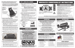
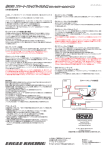
step 4–transmitter adjustments
[amount of throw at full throttle]
B. Set LOW ATV, EPA, or ATL to maximum setting.
[amount of throw at full brakes]
C. Set EXPONENTIAL to zero setting. [throttle channel linearity]
D. Set THROTTLE CHANNEL REV. SWITCH to either position.
E. Set THROTTLE CHANNEL TRIM to middle setting.
[adjusts neutral position/increases or decreases coast brakes]
F. Set ELECTRONIC TRIGGER THROW ADJUSTMENT to 70%
throttle and 30% brake throw (or 7:3)--best for reversible ESCs.
[adjusts trigger throw electronic/digital pistol-grip transmitters]
G. Set MECHANICAL TRIGGER THROW ADJUSTMENT to position
with 1/2 throttle and 1/2 brake throw.
[adjusts trigger throw on mechanical/analog pistol-grip transmitters]
•NOT ALL TRANSMITTERS HAVE THESE ADJUSTMENTS •
For proper ESC operation, adjust transmitter as follows:
A. Set HIGH ATV or EPA to maximum setting.
trouble-shooting guide
Steering Channel Works But Motor Will Not Run
• Red status LED blinking when throttle is applied. Check motor sensor harness
connection at ESC (make sure all metal sockets are fully inserted into the connector’s
plastic housing)––check for damaged wires.
• Red status LED on solid & Green LED blinking. Check input signal harness & motor
sensor harness connections at ESC. Check input signal harness wiring sequence &
connection at throttle channel of receiver. Check throttle channel operation with servo.
Motor sensor harness connected while in Brush-Mode––disconnect sensor harness.
• Blue & Green status LEDs both blinking. Possible ESC shut-down due to locked rotor
detection––return throttle to neutral position to regain motor control––check vehicle’s
drive train for free operation.
• Blue & Red status LEDs blinking. Possible ESC thermal shut-down––Check gear ratio
& free operation of drive train for possible overloading/ESC is being severely overloaded––allow system to cool & return throttle to neutral position to regain motor
control. LEDs will continue to blink until system is cooled down.
• Blue & Amber status LEDs blinking. Possible motor thermal shut-down––Check gear
ratio & free operation of drive train for possible overloading/motor is being overloaded––allow system to cool & return throttle to neutral position to regain motor
control. LEDs will continue to blink until system is cooled down.
• Blue & Green (Locked Rotor Detection), Blue & Red (ESC Thermal Shut-Down), or
Blue & Amber (Motor Thermal Shut-Down) status LEDs blinking. ESC may have shutdown & ESC’s neutral point is too far off to sense that transmitter throttle has
been returned to neutral––Refer to Steps 4 & 5.
• Possible receiver damage––Check operation with a different receiver.
• Possible internal damage––Refer to Service Procedures.
step 5– one-touch programming
With ESC connected to (at least) a receiver & a charged battery pack:
1. TURN ON THE TRANSMITTER’S POWER
2. PRESS & HOLD ESC’S ONE-TOUCH/SET BUTTON
3. TURN ON THE SPEED CONTROL’S POWER
Motor and Steering Servo Do Not Work
• Check wires, receiver signal harness wiring & color sequence, radio system, crystals,
battery/motor connectors, & battery pack.
• Possible receiver damage––Check operation with a different receiver.
• Possible internal damage––Refer to Service Procedures.
4. CONTINUE HOLDING SET BUTTON UNTIL RED LED COMES ON
5. RELEASE SET BUTTON AS SOON AS LED TURNS RED
6. PULL TRANSMITTER THROTTLE TO FULL-ON POSITION
Hold it there until the green status LED turns solid green.
Note: Motor will not run during programming even if connected.
Speed Control Runs Excessively Hot
Model Runs Slowly/Slow Acceleration
Hold it there until the green status LED blinks green.
• Gear ratio too high––Reduce gear ratio (see ‘GEAR SELECTION’).
• Check battery connectors––Replace if needed.
• Incorrect transmitter/ESC adjustment––Refer to Steps 4 & 5.
• External Power Capacitor damaged/not installed––Replace Power Capacitor.
8. RETURN TRANSMITTER THROTTLE TO NEUTRAL
Red status LED will turn solid red, indicating that speed control is at
neutral and that proper programming has been completed.
NOTE: If transmitter settings are changed, One-Touch Programming must be
repeated. If you experience any problems, turn off ESC & repeat One-Touch.
ESC Is Melted Or Burnt/ESC Runs With Switch Off
• Internal damage––Refer to Service Procedures.
REMEMBER: Whenever One-Touch set-up is performed, ESC automatically reverts to
factory default settings & the Throttle Profile reverts to #1 when in Brushless-Mode.
*For more assistance call our Customer Service Department or check our website.
service procedures
using a receiver battery pack
Before sending your speed control or brushless motor system in for
service, review Trouble-Shooting guide and instructions. System may
appear to have failed when other problems exist.
After reviewing instructions, if you feel that your ESC/system requires
service, please obtain the most current product service options and
pricing by the following ways:
If you are planning to use an external receiver battery pack to power the
electronics you need to do the following:
1. Plug the external 5 cell (1.2VDC/cell) receiver battery pack into the
battery slot of the receiver.
2. Leave the ESC’s ON/OFF switch in the OFF position, and use receiver
battery pack’s ON/OFF switch to turn the system power on and
off––Do not use the ESC’s switch.
WEBSITE: Print a copy of the PRODUCT SERVICE FORM from the CUSTOMER SERVICE
section of the website. Fill out the needed information on this form and return it with
the Novak product that requires servicing.
PHONE/FAX: If you do not have access to the internet, please contact our customer
service department by phone or fax as listed below.
WARRANTY SERVICE: For warranty work, you MUST CLAIM WARRANTY on
PRODUCT SERVICE FORM & include a valid cash register receipt with purchase date
and dealer name & phone# on it, or an invoice from previous service. If warranty
provisions have been voided, there will be service charges.
sensor harness wiring
•ESCs returned without a serial number will not be serviced under warranty•
Should any of the 26G Teflon wires pull out of the connector on the
end of the motor’s sensor harness, re-insert them in the appropriate
slot in the connector as shown below. There is a small plastic tab that
grabs a small raised barb on the back of the metal socket crimped onto
the Teflon wire’s end. The plastic tab should be checked to make sure it
has not deformed excessively before inserting the metal socket into the
plastic connector housing with the barb toward to plastic tabs.
If the motor’s
sensor harness
gets damaged,
please contact
our Customer
Service Dept.
orange
blue
white
green
plastic
tabs
metal
barbs
Input Voltage .......................................... 4-7 cells (1.2 volts DC/cell)
ESC Case Size ...................... 1.32”x1.75”x1.05” [33.5x44.4x26.7mm]
ESC Weight (w/o wires) .................................... 1.70 ounce [48.2 grams]
B.E.C. Voltage/Current ............................... 6.0 volts DC/3.0 amps
Power Wire (Battery/Motor) ............................ 14G Super-Flex Silicone
On-Resistance (Brushless-Mode).................. 0.0019Ω @25°C trans.temp.
On-Resistance (Brush-Mode) ....................... 0.0006Ω @25°C trans.temp.
Rated Current (Brushless-Mode) ....... 160A [Fwd & Rev.] @25°C trans.temp.
Rated Current (Brush-Mode) ......... 480A [Fwd & Brakes] @25°C trans.temp.
Motor Limit (Brushless-Mode) ..................... 225 watts @25°C trans.temp.
Motor Limit (Brush-Mode) ....................................................... 12-turn
Throttle Programs (Brushless-Mode) .............. 5 [3 w/Rev. & 2 Fwd/Brake]
Throttle Program (Brush-Mode) ....................................... 1 [Fwd/Brake]
#55-1705-1
2-2005
Brush & brushless motor control and programmability all in one!
The Super Sport Plus programmable electronic speed control gives you the best of both worlds--brush & sensor-based brushless motor control.
Combine this with on-board programming of Minimum Drive, Minimum Brake, Drag Brake, & Deadband, and you’ve got extreme versatility.
The Super Sport Plus is factory-loaded with 6 throttle programs to choose from (including a limited reverse Marine Mode), Novak’s Smart Braking II (you
don’t go into reverse until you shift into reverse by returning the trigger to neutral and then back to reverse), Thermal Overload Protection, high-power B.E.C. for
strong/fast servo response, Polar Drive & Digital Anti-Glitch circuitries for cool & smooth operation, and Radio Priority circuitry for the ultimate in control,
right down to the end of the charge. Add to this the user-replaceable battery wires, power capacitor, & input harness, and the Super Sport Plus has it all!
To benefit from all of the technical features of the Super Sport Plus, PLEASE READ ALL INSTRUCTIONS
• Gear ratio too low––Increase gear ratio (see ‘GEAR SELECTION’).
7. PUSH TRANSMITTER THROTTLE TO FULL-BRAKES
red
SPECIFICATIONS
Receiver Glitches/Throttle Stutters During Acceleration
• Receiver or antenna too close to ESC, power wires, battery, or motor.
• Bad connections––Check wiring, connectors, & sensor harness.
• External Power Capacitor damaged/not installed––Replace Power Capacitor.
With transmitter throttle at neutral, and still pressing the SET button,
slide the ESC’s ON/OFF switch to ON position.
black
super sport plus--INstructIons
ADDITIONAL NOTES:
• Dealers/distributors are not authorized to replace Novak products thought to be defective.
• If a hobby dealer returns your brushless system for service, submit a completed
PRODUCT SERVICE FORM to the dealer and make sure it is included with the product.
• Novak Electronics, Inc. does not make any internal electronic components (transistors,
resistors, etc.) available for sale.
raised
metal
barb
metal socket
on end of Teflon
sensor harness wires
P4
PRECAuTIONS
WATER & ELECTRONICS DON’T MIX!
REPLACEMENT POWER CAPACITOR [Novak kit #5677]
Never allow water, moisture, or other foreign materials to get inside
ESC, motor, or on the PC Boards. Water damage will void the warranty!
Schottky diodes must NOT be used when using ESC in Brushless-Mode
(Schottky diodes are never used with reversible ESCs, including brushless).
Schottky diode usage in Brushless-Mode will damage ESC & void warranty.
The Super Sport Plus comes with a factory-installed Power Capacitor, and
MUST BE USED to maintain cool and smooth operation. Direct-replacement
Super Sport Plus Power Capacitor is available in Novak kit #5677.
Note: We highly recommend using Novak Power Capacitors, as we have done
extensive testing & research to find Power Capacitors with the very best quality
factors––other capacitors with similar ratings will not provide equal protection.
TAKE CARE WHEN SWITCHING ESC MODES
SUPER-FLEX SILICONE 14G WIRE [Novak kits #5500 & 5508]
NO SCHOTTKY IN BRUSHLESS-MODE!
Severe ESC damage can occur if proper procedures are not followed
when switching ESC between Brush-Mode & Brushless-Mode.
Refer to PROGRAMMING/GEARING sheet page 5 for detailed instructions.
Novak Super-Flex wire for power wiring. 14 gauge silicone wire in kit #5500
(36”red & 36”black) and kit #5508 (2 each of 9”red/black/blue/yellow/orange).
INPUT SIGNAL HARNESS [Novak kits #5315 & 5320]
DISCONNECT BATTERIES WHEN NOT IN USE
User-replaceable input signal harness is available in both short and long
lengths. 4.5” harness in Novak kit#5315, and 9.0” harness in Novak kit #5320.
Always disconnect the battery pack from the speed control when not
in use to avoid short circuits and possible fire hazard.
SS-SERIES MOTOR END BELL & BEARING SET
4 TO 7 CELLS ONLY
After extensive use, the ball bearings in the end bells of your brushless motor may need to be replaced. Replacement front end bell with bearing factoryinstalled & rear bearing are available in Novak kit #5905.
Never use fewer than 4 or more than 7 cells (4.8-8.4VDC, 1.2VDC/cell)
in the vehicle’s main battery pack(s).
NOVAK BRUSHLESS MOTORS ONLY
The Super Sport Plus ESC is specially designed for use with sensorbased Novak SS-Series Brushless Motors Only! You may replace motor
with Novak sensored motor rated up to 225W (ESC’s rating).
At the time of printing, there are no other brushless motor’s available that work
with the Super Sport Plus––check our website for further updates & compatibilities.
product warranty
The Super Sport Plus Brushless ESC is guaranteed to be free from defects in materials or workmanship for a
period of 120 days from the original date of purchase (verified by dated, itemized sales receipt). Warranty does
not cover incorrect installation, components worn by use, damage to case or exposed circuit boards, damage
from using fewer than 4 or more than 7 cells (1.2 volts DC/cell) input voltage, cross-connection of battery/
motor power wires, overheating solder tabs, reverse voltage application, damage resulting from thermal overload
or short-circuiting motor (or connecting a brushless motor sensor harness while operating in Brush-Mode),
damage from incorrect installation of FET servo or receiver battery pack, not using or incorrect installation of a
Power Capacitor on the ESC or from using a damaged Power Capacitor, using a Schottky diode in BrushlessMode, using non-Novak Power Capacitor or motor, splices to input, ON/OFF switch, or sensor harnesses,
damage from excessive force when using the One-Touch/SET button or from disassembling case, tampering
with internal electronics, allowing water, moisture, or any other foreign material to enter ESC or get onto the
PC board, incorrect installation/wiring of input plug plastic, allowing exposed wiring or solder tabs to shortcircuit, or any damage caused by a crash, flooding, or act of God.
NO REVERSE VOLTAGE!
Reverse battery polarity can damage ESC & void warranty. Disconnect
battery immediately if a reverse connection occurs.
POWER CAPACITOR REQUIRED
An external power capacitor is installed and MUST be used with your
ESC. Failure to use Power Capacitor will result in higher ESC operating
temperatures & possible thermal shut-down.
TRANSMITTER ON FIRST
Novak Electronics, Inc.
Always turn on the power of the transmitter first so that you will have
control of the vehicle when you turn it on.
(949) 833-8873 • FAX (949) 833-1631
Customer Service e-mail: [email protected]
Monday-Thursday: 8:00am-5:00pm (PST)
Friday: 8:00am-4:00pm (closed every other Friday)
Always insulate exposed wiring with heat shrink tubing or electrical
tape to prevent short circuits, which can damage ESC.
www.teamnovak.com
optional accessories
Because Novak Electronics, Inc. has no control over the connection & use of the speed control or other
related electronics, no liability may be assumed nor will be accepted for any damage resulting from the
use of this product. Every Novak speed control & motor is thoroughly tested & cycled before leaving our
facility and is, therefore, considered operational. By the act of connecting/operating speed control, user
accepts all resulting liability. In no case shall our liability exceed the product's original cost. We reserve the
right to modify warranty provisions without notice.
©2005 Novak Electronics, Inc. • All Rights Reserved • No part of these instructions may be reproduced
without the written permission of Novak Electronics, Inc. • Super Sport Plus ESC, Smart Braking II, Polar
Drive Technology, Radio Priority Circuitry, & One-Touch Set-Up are all trademarks of Novak Electronics,
Inc. • All Novak speed controls & motors are designed & manufactured in the U.S.A.
INSULATE WIRES
NO CA GLUE
Exposure to CA glue or its fumes can cause damage to internal
components of the speed control and result in premature failure.
P1
The Super Sport Plus has the industry-standard receiver input connector
on a user-replaceable input harness & works with all major radio brand’s
new receivers. However, some very old receivers must have the wiring
sequence in the plastic 3-pin connector housing changed. This is important,
& battEry cONNEctiON
bRuSH-typE mOtOrS
mOtOrS--Note: You MUST switch ESC to Brush-Mode (see Programming/Gearing sheet)
NOvak bRuSHlESS mOtOrS (Fig.5)
1. MOTOR CAPACITORS NOT NEEDED
1. MOTOR CAPACITORS
because receiver & servo electronics may be damaged if the sequence is incorrect.
Novak brushless motors do not require external motor capacitors.
changing wiring sequence @ receiver end
2. DO NOT USE SCHOTTKY DIODES IN BRUSHLESS-MODE
Schottky diodes must NOT be used with reversible ESCs (including
brushless). Schottky diode usage will damage the ESC & void warranty.
JR • Hitec • Futaba • New KO • Airtronics Z
The Super Sport Plus comes with a factory-installed Power Capacitor,
and it MUST be used during both brushless & brush-type motor usage.
white
red
black
FIGURE 2
FIGURE 1
New KO (with tabs)
tabs
4. CHECK FOR PROPER GEARING
Refer to the ‘GEAR SELECTION’ portion of the PROGRAMMING/GEARING
Sheet (Pg.5) to determine proper gearing & avoid overheating.
*If motor has no ground tab (below), solder the capacitors to motor can.
5. SOLDER MOTOR POWER WIRES TO MOTOR
Old KO (no tabs)
no tabs
a. Cut the Super Sport Plus’ BLUE, YELLOW, & ORANGE silicone motor
power wires to the desired length, and strip 1/8-1/4” of insulation
from the end of each wire. Tightly twist the exposed strands of wire.
b . Insert the ESC’s BLUE Phase ‘A’ motor wire into the hole in the motor’s
‘A’ solder tab & solder. Use a soldering iron to apply heat to exposed
wire that extends through the PCB, and begin adding solder to tip of
soldering iron and to the wire. Add just enough solder to form a
clean & continuous joint from the plated area of the solder tab up
onto the wire. Use side cutters to trim remaining (now soldered) wire
extending beyond the solder tab (about 1/16” above PCB).
IMPORTANT NOTE: DO NOT OVERHEAT SOLDER TABS
white
black
red
Old-style KO • Old-style Sanwa/Airtronics
If you have an older KO or Sanwa/Airtronics, you must change the
sequence of the ESC’s input harness wires--Old Sanwa/Airtronics cases
are black color & Old KO cases do not have tab openings, as in Figure 2 above.
• Using a small flat blade screwdriver, remove the red & black wires from the
plastic housing at the receiver end of the input harness as in Figure 3 below.
• Interchange the red and black wires in the plastic 3-pin connector housing
at the receiver end of the input harness.
• Insert modified end of the harness into the THROTTLE CHANNEL (#2) of
receiver with the RED wire toward the outside edge of receiver case.
• Plug the other end of the input harness into the ESC with the WHITE wire
toward the ‘S’ (signal) marking on the ESC’s case.
Note: Make sure no wire strands have strayed to an adjacent solder tab, this will
result in short-circuiting & severe ESC damage, which will void the warranty.
6. PROTECT SENSOR WIRES WITH SPIRAL WRAP
Use the included spiral wrap to protect the 6 Teflon sensor harness
wires between the ESC & motor.
mount channel on the back of the ESC’s case can be used to hold the ON/OFF
switch or Power Capacitor. Be sure receiver & antenna are mounted as far from
ESC, power wires, battery, & servo as possible--these components all emit RF noise
when throttle is applied. On graphite or aluminum chassis vehicles, it may help to
place receiver on edge with crystal & antenna as far above chassis as possible.
Note: Mount antenna as close to receiver as possible--trail any excess wire off top
of antenna mast (cutting or coiling excess antenna wire will reduce radio range).
STATUS LEDs (Fig.6)
2. SECURE POWER CAPACITOR TO SLIDE-MOUNT BRACKET OR CHASSIS
Use included P.Cap bracket to
mount Power Capacitor to the
Power Cap.
tie-wrapped
ESC’s slide-mount channel or
to bracket
tape it to the chassis with the
included double-sided tape
(Capacitor can also be tie-wrapped
to the power wires) . To use slide
mount channel, slide P.Cap
bracket into channel on the ESC
& secure Power Capacitor to the
bracket with tie-wraps.
3. INSTALL ON/OFF SWITCH
using a screw or the included
double-sided tape where it will
be easy to access.
The switch is also designed to be
installed into the ESC’s slide
mount channel.
Slide
mount
ON/OFF
switch
P2
User-replaceable input
signal harness (Ch.2)
Servo
plugged
into
steering
ch. (#1)
4 to 7 cell
battery pack
PowerCap
wires
One-Touch
Set-Up
button
Sensor
Harness
bundled with
Spiral Wrap
(–)
Tamiya-style
battery connector
(+)
Blue
LED
Red
LED
Amber Green
LED
LED
Novak
sensor-based
brushless motor
Black power wire
(battery negative)
BRUSH-MODE
‘Y’ Method (Fig.8)
BRUSHLESS-MODE SET-UP
PHOTO (FIGURE 5)
flow, it will run cooler; and that means it will be more efficient, and you will go faster!
1. MOUNT ESC IN VEHICLE using included double-sided tape. The slide-
Orange power wire
(motor phase ‘C’)
Status LEDs
FF
/O ch
ON wit
s
Mount ESC with power wires away from other electronics & moving parts.
Select a location that allows airflow through heat sinks--If the ESC gets air
Blue power wire
(motor phase ‘A’)
Yellow power wire
(motor phase ‘B’)
Red power wire
(battery positive)
brush-type
motor
(+)
(–)
using a single wire method
method (Fig.7)
a. Strip 1/4-3/8” piece of insulation from the mid-section of the ESC’s
RED silicone power wire where you will solder it to either battery
pack POSITIVE (+) or the POSITIVE (+) motor tab (whatever component
is in the middle). Tin the exposed section of wire with solder.
b. Solder the exposed section of the ESC’s power wire to battery pack
POSITIVE (+) or the POSITIVE (+) motor tab.
c. Strip & tin the end of the ESC’s RED power wire (after the first
connection), and solder it to the final component--either battery pack
positive (+) or the positive (+) motor tab.
4. SOLDER ESC’S BLACK WIRE TO BATTERY PACK NEGATIVE (–)
5. PREP & SOLDER ESC’S BLUE, YELLOW, & ORANGE WIRES
With brush-type motors, the Super Sport Plus’s BLUE, YELLOW, & ORANGE
motor phase power wires must all go to the NEGATIVE (–) motor tab.
a. Strip 1/8-1/4” of insulation from the end of the BLUE, YELLOW, &
ORANGE motor phase wires. Twist & tin the end of each of the wires.
b. Solder all of the motor phase wires (BLUE, YELLOW, & ORANGE) to
the NEGATIVE (–) motor tab.
Racing Schottky Motor Modules are available in Novak kit #5636.
Trail excess wire off top
of antenna mast
Power Capacitor tie-wrapped to
slide-mount bracket
:
Ground / motor can
If Schottky diode is installed backwards it will be destroyed. Replace only with
Schottky diodes with a minimum rating of 35 volts/8 amps.
Connect the speed control’s Tamiya-style JST battery connector to a
charged 4 to 7 cell (1.2VDC/cell) battery pack.
ESC
Schottky diode
Positive (+) motor tab
The Super Sport Plus does not require an external Schottky diode under
most brush motor conditions. Note that an external Schottky will optimize
the ESC’s braking and motor performance in applications with heavy or
repeated braking (lap after lap), or when using lower turn modified motors.
• If using an axial lead Schottky diode as shown in the photo above (older
Novak style--35V/8A min.), solder lead CLOSEST to the silver stripe on the
Schottky diode’s body to the POSITIVE (+) motor tab. Solder the lead
OPPOSITE the silver stripe on the body to the NEGATIVE (–) motor tab.
• If using the Novak Racing Schottky Motor Module (this is the best performing
Schottky diode available), solder the RED wire from the module to the
POSITIVE (+) motor tab. Solder the BLACK wire from the Schottky module
to the NEGATIVE (–) motor tab.
7. CONNECT SPEED CONTROL TO BATTERY PACK
step 2– MOUNTiNG
0.1µF Capacitors
2. INSTALLING OPTIONAL SCHOTTKY DIODE (Brush-Mode Only)
Prolonged/excessive heating of solder tabs (motor or ESC) will damage PCB.
With a small standard screwdriver, gently lift plastic
prong until wire and metal socket easily slide out of plastic housing.
Negative (–) motor tab
Extra 0.1µF capacitors are available in Novak kit #5620.
c . Solder the ESC’s YELLOW Phase ‘B’ motor wire to the motor’s ‘B’ solder
tab as described in Step 5B above.
d. Solder the ESC’s ORANGE Phase ‘C’ motor wire to the motor’s ‘C’
solder tab as described in Step 5B above.
FIGURE 3
:
using a “y” wiring method
method (Fig.8)
a. Strip 1/4-3/8” piece of insulation from the mid-section of the ESC’s
RED silicone power wire where you want to split and go to the motor
& battery. Tin the exposed section of wire with solder.
b. Slide the supplied piece of heat shrink tubing over the ESC’s RED
power wire, and slide it all the way to the ESC.
c. Strip 1/4” of insulation from the end of another piece of RED silicone
power wire. Twist & tin the wire, then solder it to the tinned section
along the ESC’s RED power wire & shrink the tubing over the solder
joint with a heat gun (a lighter or match also works well).
d. Strip & tin the end of the ESC’s RED power wire (after the “Y”), and
solder it to the POSITIVE (+) motor tab.
e. Cut the other RED power wire (after the “Y”), to the proper length so
it will reach battery pack POSITIVE (+). Strip & tin the end of the wire
and solder it to battery pack POSITIVE (+).
Solder 0.1µF (50V) capacitors between:
• POSITIVE (+) motor tab & NEGATIVE (–) motor tab.
• POSITIVE (+) motor tab & GROUND tab*.
• NEGATIVE (–) motor tab & GROUND tab*.
If Power Cap. becomes dented or damaged, ESC failure can occur--replace immediately.
Longer Power Capacitor wires will decrease performance.
• Plug one end of the input signal harness into the THROTTLE CHANNEL (#2)
of receiver with the BLACK wire toward the outside edge of receiver case.
• Plug the other end of the input harness into 3-pin header inside the ESC’s
case with the WHITE wire toward the ‘S’ (signal) marking on the ESC’s case
above the rectangular signal harness opening.
To use the Super Sport Plus with brush-type motors, the RED power wire
must go to both battery POSITIVE (+) & the POSITIVE (+) motor tab.
Note: Some motors come with built-in capacitors. If your motor only has 2 capacitors,
you need to install a capacitor between the positive & negative motor tabs––If you
experience radio interference with built-in capacitors only, install external ones.
3. FACTORY-INSTALLED POWER CAPACITOR REQUIRED
JR, Hitec, Futaba, new KO, & Airtronics Z receivers do not need input
harness re-wiring. Airtronics Z receivers have blue plastic cases & new KO
cases have tabs on the input harness openings as in Figure 1.
3. PREP & SOLDER SPEED CONTROL’S RED WIRE
Electric brush-type motors generate RF noise that causes interference.
The included 0.1µF (50V) non-polarized, ceramic capacitors must be used
on all motors to reduce motor noise & prevent ESC damage.
(+)
(–)
‘Y’ type
connection of
Red power wire
(battery & motor
positive)
BRUSH-MODE SET-UP PHOTO
Single Wire Method (FIGURE 7)
step 3– motor
input harness
FIGURE 4
step 1 – connect
brush-type
motor
Power Capacitor
tie-wrapped to
slide-mount bracket
Trail excess wire off top of antenna mast
ON/OFF switch
Status LEDs
Sensor Harness
disconnected
One-Touch
Set-Up
button
User-replaceable input
signal harness (Ch.2)
(+)
Black power wire
(battery negative)
Blue, Yellow,
and Orange
motor phase
wires connect to
motor negative
Servo
plugged
into
steering
ch. (#1)
4 to 7 cell
battery pack
(–)
(–)
(+)
In-Line connection
of Red power wire
(battery & motor
positive)
connector usage
If you are going to use connectors, we suggest Dean’s Ultra or other
low-loss connectors--do not use crimp types. To prevent possible crossconnection of motor phase wires, we do not recommend using connectors
on the motor power wires of sensor-based brushless motors.
• Use connectors that cannot be plugged in backwards. Reverse voltage
will damage the ESC and void warranty.
• Use a female connector on battery packs to avoid shorting.
For additional information on connector usage, visit our website.
P3
www.teamnovak.com