1
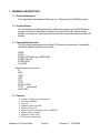
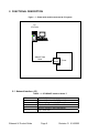
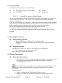
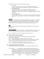
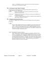
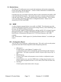
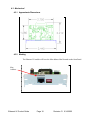
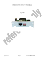
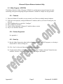
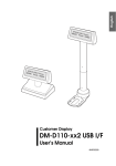
ETHERNET IV
PRODUCT GUIDE
010620A / 020415C
Documentation Version D
Description
CyberData Number
010620
020415
760430C
760431C
990414
Procurement Number
BOM Number
PROG,ETHERNET IV,DONGLE LOAD
PROG,ETHERNET IV,TFTP LOAD
PCB Number
Revision
Level
A
C
V1.02
V1.02
A
Date
12/05/02
07/24/03
01/12/04
01/12/04
1/23/03
Appendices Revisions
Appendix
A
B
C
D
Description
Ethernet IV Printer Compatibility Matrix
Epson Host Applications
Epson Ethernet Interface Utility
Epson Ethernet IV Connect-it™ Module Installation
Revision
Level
Rev: E
Rev: 6
Rev: B
Rev: C
Date
04/05/05
04/17/03
07/30/03
08/30/04
TABLE OF CONTENTS
1.
GENERAL DESCRIPTION .................................................................................................4
1.1
Product Description .....................................................................................................................4
1.2
Product Design.............................................................................................................................4
1.3
Compatability Overview..............................................................................................................4
1.4
Features........................................................................................................................................4
1.5
Device Identification ...................................................................................................................5
2.
FUNCTIONAL DESCRIPTION............................................................................................6
2.1
Network Interface (J3)................................................................................................................6
2.2
LED Indicator ..............................................................................................................................7
2.3
Dip Switch Settings .....................................................................................................................7
2.4
Junper Settings.............................................................................................................................8
2.5
Operating Environment ...............................................................................................................8
2.5.1
Host Operating Systems ......................................................................................................8
2.5.2
Supported Printers ...............................................................................................................8
2.6
Printing Functionality ..................................................................................................................8
2.6.1
Epson Host Applications .....................................................................................................8
2.6.2
Basic Communications Protocols ........................................................................................9
2.6.3
Printing Communications Protocols ....................................................................................9
2.6.4
Configuration and Control Protocols.................................................................................10
2.6.5
Address Assignment Protocols ..........................................................................................10
2.7
Module Configuration ...............................................................................................................11
2.7.1
Remote Configuration .......................................................................................................11
2.8
Module Status ............................................................................................................................13
2.8.1
SNMP ................................................................................................................................13
2.8.2
Configuration Report .........................................................................................................13
2.8.3
Epson Self-Test..................................................................................................................15
3.
PRINTER INTEGRATION AND OPERATION ..................................................................16
3.1
Printer setup. ..............................................................................................................................16
3.2
Programming the Flash Memory ...............................................................................................16
3.3
Serial Number and Mac Address Pprogramming ......................................................................16
4.
REQUIREMENTS .............................................................................................................17
4.1
Maximum Ratings .....................................................................................................................17
4.2
Electrical ....................................................................................................................................17
4.2.1
DC Characteristics .............................................................................................................17
4.3
Mechanical.................................................................................................................................18
4.3.1
Approximate Dimensions ..................................................................................................18
4.3.2
Marking..............................................................................................................................18
4.4
Environmental............................................................................................................................19
4.4.1
Operating Conditions.........................................................................................................19
Ethernet IV Product Guide
Page 2
Revision: D 6/14/2005
4.4.2
Storage Conditions.............................................................................................................19
4.5
Regulatory..................................................................................................................................19
4.5.1
Safety .................................................................................................................................19
4.5.2
Emissions...........................................................................................................................19
4.5.3
Immunity............................................................................................................................19
5.
APPENDICES ...................................................................................................................20
5.1
Ethernet IV Printer Compatibility Matrix..................................................................................20
5.2
Ethernet IV Host Applications.....................................................................................................1
5.3
Utility Program – EEIUTIL4.......................................................................................................2
5.3.1
Features................................................................................................................................2
5.3.2
Printers Supported ...............................................................................................................2
5.3.3
Start Up................................................................................................................................2
5.3.4
Screen Description...............................................................................................................3
5.3.5
Device Listing Area.............................................................................................................4
5.4
Module Installation.................................................................... Error! Bookmark not defined.
Ethernet IV Product Guide
Page 3
Revision: D 6/14/2005
1. GENERAL DESCRIPTION
1.1 Product Description
This specification describes the Ethernet Ver. IV Module for the EPSON printers.
1.2 Product Design
The E4 product is the latest generation of Ethernet products for the EPSON line of
printers. The E4 was designed to replace the function limited E3 and the higher
priced E2 modules all a cost objective that meets the same delivered price as the E3
module.
1.3 Compatability Overview
The E4 module was designed for a Retail POS specific environment. Compatibility
with Retail applications interfaces include:
OPOS
JPOS
EPSON TM Flash Logo (TMFLOGO)
EPSON Tool Kit
EPSON APD
Port 9100
Supported protocols include:
IP
ARP
ICMP
UDP
TCP
HTTP
DHCP CLIENT
TFTP
(download)
ARP-PING
1.4 Features
10 Base-T Ethernet Communications
Field Programmable
Low cost
Standard UIB size module
High speed Sync I/F
Discovery and configuration utility (EEIUtil4)
Offline report generation
Diagnostic Status LED
Web based configuration
Ethernet IV Product Guide
Page 4
Revision: D 6/14/2005
1.5 Device Identification
Product name: Ethernet IV (E4)
Board Identification: 990414A
Part Number: 010620A / 020415C
Ethernet IV Product Guide
Page 5
Revision: D 6/14/2005
2. FUNCTIONAL DESCRIPTION
Figure – 1 - Printer with module connected to PC system
PC
STATION
10BaseT Data
Cable
E IV
Module
Printer
2.1 Network Interface (J3)
TABLE – 3 – ETHERNET Interface 10base-T
PIN
1
2
3
6
4,5,7,8
Ethernet IV Product Guide
DESCRIPTION
Transmit Positive side Differential
Transmit Negative side Differential
Receive Positive side Differential
Receive Negative side Differential
No Connection
Page 6
Revision: D 6/14/2005
2.2 LED Indicator
When the module comes up it will initially blink at a rapid rate – After that, there are 5
modes of blinking:
1. 3 Blinks per second means there is no Ethernet Cable connected.
2. 20 Blinks per second on module initialization unless 10base-T connection.
3. Solid ON means that there IS a LINK 10base-T (but no data).
4. 50ms blink for data.
5. Solid OFF means the unit is NOT functioning.
2.3 Dip Switch Settings
The E4 has 4 user accessible dipswitches (SW1) on the front panel of the module.
These switches allow different functions depending on the position of the switch.
DSW1
DSW2
DSW3
DSW4
ON – Prints configuration report on power up
OFF – Normal
ON – Not Defined
OFF – Not defined
ON – Not Defined
OFF – Not defined
ON – Change device settings (IP Address, Gateway, Subnet mask,
DHCP enable/disable, Device name, Print port) via web interface, ARP/PING, or
configuration protocol or any future methods.
OFF – Lock settings
Figure – 3 – Component Locations
SW1
JP1
JP2
DS1
U3
TP3
U2
U4
XT1
L1
D3
J2
VR2
TP2
VR1
TP1
C1
TP5
J1
Ethernet IV Product Guide
TP6
TP4
Page 7
Revision: D 6/14/2005
2.4 Junper Settings
The E4 has 2 on-board jumpers as shown in Figure 3.
JP1
JP2
ON – Reconfigure to factory default settings
ON – Not Defined
OFF – Normal
OFF – Not Defined
2.4.1.1.1
Using JP1 to Return to Default Settings
JP1-ON forces the module to use the factory default settings for configuration. All settings are
returned to their default values. The unique, factory assigned Ethernet Address and Serial
Number are maintained.
To use JP1, turn the power off to the printer. Remove the E4 module from the printer. Install the
jumper across JP1. Install the module back into the printer. Power on the printer. Wait for the
printer to initialize (printer feeds paper once), then power down the printer again.
Remove the E4 module from the printer and remove the jumper from JP1.
Re-install the E4 back into the printer and power back up.
The E4 is now running with default settings and can be configured using the various utilities
provided.
2.5 Operating Environment
2.5.1 Host Operating Systems
• Microsoft Windows 95, Windows 98, and Windows 2000
Windows NT, Windows XP, Linux (via raw TCP sockets, no driver or utilities
available)
2.5.2 Supported Printers
The Ethernet IV module will operate in the following Epson POS printers:
• See Appendix A for specific printer support
Note: Only Sync I/F printers are supported
2.6 Printing Functionality
2.6.1 Epson Host Applications
• The Ethernet IV module is designed to support and enhance communications with
host printing processes developed under the following Epson Application
Development environments:
OPOS
OLE for Retail POS provides an open device driver architecture that allows Point-of-Sale
hardware to be easily integrated into POS systems based on the Microsoft Windows
environment.
The goals include:
• Define an architecture for Win32-based POS device access.
• Define a set of POS device interfaces sufficient to support a range of POS
solutions.
Ethernet IV Product Guide
Page 8
Revision: D 6/14/2005
The OPOS architecture is based on the following constructs:
• Device Class
A device class is a category of POS devices that share a consistent set of
properties, methods, and events. Examples are Cash Drawer and POS Printer.
• Control Object (CO)
A Control Object exposes a set of properties, methods, and events to an
application for its device class. This allows the CO to be developed
independently of the SO's for the same class – including development by different
companies.
• Service Object (SO)
A Service Object is called by a Control Object to implement the OPOS-prescribed
functionality for a specific device. It exposes a set of methods that are called by a
CO.
ESC/POS
A POS printer command system consisting of Epson proprietary commands. Compatible
with all types of Epson POS printers and displays, ESC/POS is designed to reduce the
processing load on the host computer in POS environments. It comprises a set of highly
functional and efficient commands fully realizing the potential of Epson printers.
APD
The Epson Advanced Printer Drivers allow Windows applications to talk to Epson TM
POS printers.
Custom Applications
Any custom application can use the Ethernet V, without JPOS, OPOS, or APDs as long as
it has a working TCP/IP stack and can make use of the Epson ESC/POS commands.
Note: see Appendix B for Version level support of Host system drivers
2.6.2 Basic Communications Protocols
The Ethernet IV module supports the following industry standard underlying
communication mechanisms:
• IP
Internet Protocol provides end-to-end network connectivity
• ARP Address Resolution Protocol provides media access control address resolution
• ICMP Internet Control Message Protocol provides error and control reporting
• UDP User Datagram Protocol provides connection-less service
• TCP Transmission Control Protocol provides connection-oriented service
2.6.3 Printing Communications Protocols
The Ethernet IV module receives print data on a user configurable TCP port number:
• TCP Port 9100
raw data and ESC/POS information is transferred by direct
streaming socket communication. This type of connection is used to transfer all
POS receipt text and printer control data. TCP provides a reliable mechanism
ensuring that all print data is received. The Ethernet IV module allows one active
TCP Port 9100 connection at a time. Subsequent connection attempts to port
9100 are denied at the transport protocol level until the active connection is
Ethernet IV Product Guide
Page 9
Revision: D 6/14/2005
closed. A configurable parameter is provided to allow receipt of this type of
connection on an alternate port number.
2.6.4 Configuration and Control Protocols
The Ethernet IV module supports the following communications protocols for its
configuration and control applications:
• HTTP
Hyper-Text Transfer Protocol provides connectivity for web-page
formatted communication
• Discovery
Network discovery protocol – The Discovery Protocol for Ethernet IV is
available upon request.
• TFTP
Trivial File Transfer Protocol provides the communication mechanism for
upgrading the Ethernet IV firmware
2.6.5 Address Assignment Protocols
The Ethernet IV supports the following protocols for IP address and network parameter
assignment:
• DHCP
Dynamic Host Configuration Protocol is a method to automatically obtain an IP
Address, subnet mask, gateway and other TCP/IP related parameters on system
restart. In order to use this method successfully, a DHCP compliant server must
be properly configured somewhere on the network. Using DHCP excludes the use
of manual IP Address assignment options.
• ARP / Ping Method for setting IP Address
ARP / Ping provides a proprietary mechanism for changing an Ethernet IV IP
Address. This method is useful for initially configuring a device or recovering an
incorrectly configured device. Sending the module a special ICMP echo request
command changes the Ethernet IV IP Address. This mechanism is able to correct
the configuration of modules that are configured incorrectly, with addressing that
does not match their current network. This functionality may be enabled or
disabled by dipswitch setting on the module.
Ethernet IV Product Guide
Page 10
Revision: D 6/14/2005
2.7 Module Configuration
2.7.1 Remote Configuration
The Ethernet IV provides two mechanisms for module configuration.
•
EEIUtil4
EEIUtil4 is a Windows based utility program used for test, firmware upgrade, and
parameter configuration.
•
Epson printer Web interface configuration
The interface’s Web configuration supports Ethernet IV module configuration via
standard Internet browser.
2.7.1.1
EEIUtil4 (Epson Ethernet Interface Utility)
See Appendix C for EEIUtil4 instructions
2.7.1.1.1
Operating Environment
EEIUtil4 runs with the following versions of Windows:
• Windows 98/NT/2000/XP
When using OS later then Windows 98, user should be set up with administrator
privileges.
2.7.1.1.2
Functionality
EEIUtil4 provides the following functionality:
• Discovery of Printers.
All CyberData Ethernet IV connect-it modules are discovered via the
Network discovery protocol. Discovered printers are conveniently
displayed in the EEIUtil4 discovery window. Any of the displayed printers
may be easily selected for configuration, test, or upgrade.
• Printer general information display.
By clicking on a discovered printer and then clicking on the configure
button, a dialog box appears with all important module configuration
parameters.
• Printer Test.
A test button is provided to easily initiate status report generation to any of
the discovered printers.
• Programming of ROM image for firmware upgrade
• Module firmware can be easily upgraded over the network via TFTP.
Ethernet IV firmware is programmed and stored into the module’s internal
flash memory.
• IP Address modification/
Ethernet IV Product Guide
Page 11
Revision: D 6/14/2005
2.7.1.2
Printer Setup Web Configuration
2.7.1.2.1
Operating Environment
The Epson Printer Setup Web Configuration interfaces with the following Internet
browsers:
• Microsoft Internet Explorer 5.0 or greater
• Netscape Navigator 7.0 or greater
2.7.1.2.2
Functionality
The Epson Printer Setup Web Configuration provides the following functionality:
(The configurable module parameters are password protected)
Network Settings Configuration page
• Protocol Enable/Disable
DHCP
•
Manual IP Address settings
IP Address
Netmask
Gateway
• Application Settings Enable/Disable
Port 9100 printing
Alternate port printing
Printer Status page
• Test of printer/module functionality by initiating status report generation
Ethernet IV Product Guide
Page 12
Revision: D 6/14/2005
2.8 Module Status
The Ethernet IV module passes most control and maintenance information transparently
between the printer and the application. A subset of status information is maintained and
reported by the Ethernet IV module.
On printer power-up, the module solicits the printer for basic information and enables ASB
(Auto Status Back) functionality. This instructs the printer to transmit status information
when the status changes. The module maintains these statuses and others. These statuses
can be queried by the printing application or configuration utilities. Statuses can be
obtained by ESC/POS, and SNMP.
2.8.1 SNMP
A subset of printer-managed objects is accessible via SNMP. This information provides
operational information required to increase networking efficiency, status monitoring, error
recovery, and EPSON printing performance.
The EIV provides support for agent operations as defined in RFC1157 (A Simple Network
Management Protocol), encoding of information as defined in RFC1155 (Structure and
Identification of Management Information for TCP/IP-based Internets), and a MIB
compiler.
Note: The document “ SNMP support for CyberData Ethernet Modules” is available upon
request.
2.8.2 Configuration Report
There are four ways to generate a configuration report. This can be used to test the printer
operational status and to obtain important module and printer parameters.
DIP Switch 1
Set DIP switch 1 on the Ethernet IV module to ON.
A configuration report will be automatically generated during module firmware
initialization. This report is generated each time on power-up as long as dip 1 is
ON.
EEIUTIL4 Test.
Click the TEST button in the program screen to initiate a configuration report.
Cover Open
Open the printer cover, press the FEED button, and then close the printer cover.
For this option, the printer must have a cover sensor (TM-U200 series does not).
Web Page
Click the printer status button on the web page.
Ethernet IV Product Guide
Page 13
Revision: D 6/14/2005
Figure – 4 – Status Report
EPSON TM-L90
EthernetIV Interface
IP ADDRESS:
GATEWAY:
SUBNET MASK:
DHCP:
192.168.1.227
192.168.1.1
255.255.255.0
DISABLED
DEVICE NAME:
MAC ADDRESS:
PRINT PORT:
Epson L90
00:20:F7:CB:00:00
9100
DIP SWITCHES:
1 2 3 4
: : : :
I/F FW VER:
I/F SERIAL NO:
1.01 10/01/03
620000000
PRINTER FW VER:
1.04 ESC/POS
PRINTER SERIAL NO: DEJK000151
LINES PRINTED:
ENERGIZE COUNT:
NUMBER OF CUTS:
OPERATION TIME:
Ethernet IV Product Guide
Page 14
25056
472536
115
21
Revision: D 6/14/2005
2.8.3 Epson Self-Test
By holding down the “FEED” button while powering on the printer, the Epson printer prints
a printer self test. This provides more detailed printer information and – on select printers –
also provides some basic module information.
Figure – 5 – Epson Self-Test
Firmware Version 7.00 ESC/POS
Interface Ethernet IV v1.01
Name :CyberData Ethernet IV
(010620A)
SN :620000000
MAC :00:20:F7:CB:00:00
Buffer Capacity
4K bytes
Handshaking Operation (busy condition)
Receive buffer full
Resident Character
Alphanumeric
Print Density
LIGHT [ 1 2 3 ] DARK
^
If you want to continue SELF-TEST
printing, please press FEED button.
Ethernet IV Product Guide
Page 15
Revision: D 6/14/2005
3. PRINTER INTEGRATION AND OPERATION
3.1
Printer setup.
Note: See appendix D for Specific Printer configuration information
3.2 Programming the Flash Memory
Firmware updates can be uploaded by use of EEIUtil4
3.3 Serial Number and Mac Address Pprogramming
The product serial number and MAC address is programmed during the manufacturing process by use of
a special utility. This is an “at time of manufacturing” feature only.
Ethernet IV Product Guide
Page 16
Revision: D 6/14/2005
4. REQUIREMENTS
4.1 Maximum Ratings
The following ratings shall not be exceeded:
Storage temperature
-40° C to +60° C
Operating temperature
0° C to +50° C
Relative Humidity
20% to 80% without condensation
Maximum supply voltage 5.5 VDC (Vcc to Vss)
30.0 VDC Printer Supply Voltage
4.2 Electrical
4.2.1 DC Characteristics
+5 volts as supplied by the Epson Printer to use less than 100ma.
Ethernet IV Product Guide
Page 17
Revision: D 6/14/2005
4.3 Mechanical
4.3.1 Approximate Dimensions
4.3.2 Marking
The Ethernet IV module will have the Mac address label located on the front Panel.
Mac
Address
Ethernet IV Product Guide
Page 18
Revision: D 6/14/2005
The Ethernet IV module will have the 01-02 assembly numbers, The Serial Number
and firmware version number located on the back of the Panel.
Serial
Number
01-02 #s
Firmware
Version
Example
4.4 Environmental
4.4.1 Operating Conditions
Temperature: 5° C to 55° C
Relative Humidity: 10% to 90%
4.4.2 Storage Conditions
Temperature Range: -10° C to 50° C (14° F to 120° F)
Temperature Change: 15° C (27° F) per hour
Humidity Range: 10% to 90% R.H.
4.5 Regulatory
4.5.1 Safety
Ul 60950 (Recognized Component) IEC/EN 60950
4.5.2 Emissions
FCC Class A – EN55022
4.5.3 Immunity
EN55024
Ethernet IV Product Guide
Page 19
Revision: D 6/14/2005
5. Appendices
5.1 Ethernet IV Printer Compatibility Matrix
Ethernet IV Printer Compatibility Matrix
Part Number:
Firmware Version:
Hardware Version:
010620A
0.20T
990414A
Printer Information
Printer Type
APD Information
OPOS Information
Model
BIOS Revision
OPOS Version
Device Type
Rcpt Health Slip Health Check
Check
MICR
Health
Check
Tscan Check
Capabilities
Version
Device
Windows Test Print Port 9100
Direct
Notes
TM-T88III
M129C
7.00 ESC/POS
2.30E UPOS 1.7
TM-T88IIIE
Pass
N/A
N/A
N/A
Pass
2.09E
TM-T88III Receipt
Pass
Pass
*4
TM-U200B
M119B
1.27 ESC/POS
2.30E UPOS 1.7
TM-U200BE
Pass
N/A
N/A
N/A
Pass
2.09E
TM-U210B Receipt
Pass
Pass
*1 *2
TM-T90
M165A
1.06 ESC/POS
2.30E UPOS 1.7
TM-T90E
Pass
N/A
N/A
N/A
Pass
2.09E
TM-T90 Receipt
Pass
Pass
*4
TM-L90
M165B
1.04 ESC/POS
2.30E UPOS 1.7
TM-L90E
Pass
N/A
N/A
N/A
Pass
2.09E
TM-L90 Receipt
Pass
Pass
*4
TM-U220
M188B
3.03 ESC/POS
2.30E UPOS 1.7
TM-U220BE
Pass
N/A
N/A
N/A
Pass
2.09E
TM-U220B Receipt
Pass
Pass
*2, *3
TM-U230
1.02 ESC/POS
2.30E SP3
TM-U230E
Pass
N/A
N/A
N/A
Pass
2.09E
TM-U230 Receipt
Pass
Pass
TM-H6000II (781)
M147E
7.01 ESC/POS
2.30E UPOS 1.7
TM-H6000IIE
Pass
Pass
Pass
Pass
Pass
2.09E
TM-H6000II Receipt
Pass
Pass
TM-H6000II (781)
M147E
7.01 ESC/POS
-
-
-
-
-
-
-
2.09E
TM-H6000II Slip
Pass
Pass
TM-H6000II (781)
M147E
7.01 ESC/POS
-
-
-
-
-
-
-
2.09E
TM-H6000II Endorse
Pass
Pass
TM-U325
M133A
1.03 ESC/POS
2.09E
TM-U325 Receipt
Pass
Pass
TM-U325
M133A
1.03 ESC/POS
2.09E
TM-U325 Validation
Pass
Pass
TM-U675
M146A
1.30 ESC/POS
TM-U675
M146A
1.30 ESC/POS
2.30E UPOS 1.7
2.30E UPOS 1.7
-
TM-U325E
Pass
TM-U675E
Pass
-
Pass
-
Pass
-
N/A
-
N/A
-
Pass
-
Pass
Pass
TM-U675 Slip
Pass
Pass
-
2.09E
TM-U675 Validation
Pass
Pass
2.09E
TM-J7100 Receipt
Pass
Pass
1.30 ESC/POS
1.01 ESC/POS
TM-J7100
M184A
1.01 ESC/POS
-
-
-
-
-
-
-
2.09E
TM-J7100 Slip
Pass
Pass
TM-J7100
M184A
1.01 ESC/POS
-
-
-
-
-
-
-
2.09E
TM-J7100 Endorse
Pass
Pass
Pass
-
TM-U675 Receipt
2.09E
M146A
Pass
-
2.09E
-
M184A
Pass
-
Pass
TM-J7100
TM-J7100E
-
N/A
TM-U675
2.30E UPOS 1.7
-
N/A
N/A
N/A
*1 APD not available for this model
*2 Capabilities not available: Toolkit was used to print receipt from template
*3 Capabilities run as model U200
*4 Capabilities run as T88II
*5 Capabilities not available; instead form validation tests were performed from toolkit
*6 Capabilities not available; instead batch report and validation self test run from toolkit
Other Compatible Programs
Program Name
TMNet WinConfig
Version
1.00
TMFlashWriter for Windows
TM Flash Logo
2.00
2.0.1
Appendix A
Caveats
“Firmware update” function not supported. Configuring a module with invalid IP settings from offnetwork, requires participating routers to permit IP broadcast address 255.255.255.255
Fully Compatible
Fully Compatible
Page 1
Revision: E 6/14/2005
*6
*5
*4
5.2 Ethernet IV Host Applications
Application
Epson Toolkit
OPOS
JPOS
ADV. Printer
Drivers
Appendix B
Version
Version Unknown
2.2.0E SP3
All
2.09E
Status
See Appendix A
See Appendix A
Not Tested
See Appendix A
Page 1
Revision: 6 6/14/2005
ETHERNET IV UTILITY PROGRAM
July 2003
Appendix C
Page 1
Revision: B 6/14/2005
Ethernet IV Epson Ethernet Interface Utility
5.3 Utility Program – EEIUTIL4
The Ethernet Interface Utility 4 Program (EEIUtil4) is a multipurpose program designed to make
interfacing, testing and configuring the Epson Ethernet IV module in a simple one step procedure.
5.3.1 Features
1) Discovers Ethernet IV modules on your network even if there are multiple network adapters.
2) Will find even improperly configured Ethernet IV modules, and let you fix the IP setting for your
network.
3) Select highlighted device and click “Configure”
4) Has a simple test procedure.
5) Can be used to reprogram a Ethernet IV modules (future version)
6) Easy to use Windows interface.
5.3.2 Printers Supported
See appendix A
5.3.3 Start Up
1) Run the Utility Program by either double clicking on the EEIUTIL4.EXE program, or selecting it
from the RUN – Browse Dialog box.
2) Click “Scan” to discover Ethernet IV modules on the network
3) If (when) the list fills in with discovered modules and the “Configure Selected” button becomes
available, click the “Configure Selected” button to configure the module.
Appendix C
Page 2
Revision:B 6/14/2005
Ethernet IV Epson Ethernet Interface Utility
5.3.4 Screen Description
Figure 2A & 2B & 2C & 2D are examples of an initial screen view. This views may vary, depending on
how many modules are on the same network as the device.
Figure – 2A – Initial Screen for the EEIUTIL (EEICP)
Title Bar and
Version Number
General Message
Area
Device Listing
Area
Action
Buttons
Figure – 2b – Initial Screen for the EEIUTIL (EEICP)
Title Bar and
Version Number
Device Listing Area
– Notice T88 Printer
is selected
(highlighted)
Action
Buttons
Figure – 2c – Initial Screen for the EEIUTIL (EEICP)
Window for Configure selected button
Appendix C
Page 3
Revision:B 6/14/2005
Ethernet IV Epson Ethernet Interface Utility
5.3.5 Device Listing Area
To select a device click on it in the device list area
The Test, and Configure buttons control the selected device. A programming button will be available in
a future version,
5.3.5.1 Exit Button
When you are finished with the EEIUtil4, click the Exit Button to terminate the program and return to
Windows.
5.3.5.2 Test Button
The Test button causes a configuration report to be printed on the selected device.
5.3.5.3 Configure Button
The Configure button brings up a dialog box allowing the user to change the selected module’s settings.
After the device has been configured, EEIUtil4 will allow some time for the module to reconfigure itself
and will then rescan the network to find the reconfigured device as well as any other Ethernet IV
modules.
5.3.5.4 Program Button
Not available now. Will be available on future version.
Appendix C
Page 4
Revision:B 6/14/2005
Ethernet IV Connect-it™ Module Installation
5.4 Module Installation
J7100
Switch Bank 1
The Ethernet IV Module works with the following EPSON printers: TM-T88III, TMU200B/D, TM-90, TM-L90, TM-U230, TM-U220,
TM-H6000II, TM-U325, TM-U675, and TM-J7100. OPOS 2.20E SP3 compatibility
is verified with TM-T88III, TM-U200B, TM-T90/L90, TM-U230, TM-H6000II, TMU325, TM-U675 and the TM-J series.
All
TM-T90, TM-L90
Switch Bank 1
Various
Memory Switch 1
Transmit Power On Information
Receive Buffer Size
Condition for BUSY
Data processing for receive error
Automatic line feed
Pin #31 reset
Pin #6 reset
Pin #25 reset
2-1
2-2
All others
Reserved
Autocutter
Reserved
On
Off
On
Off
Off
On
On
On
On
User
Off
Various
Reserved
Autocutter
Reserved
8-8
Printer cover open recovery
All others
1-8
All others
Condition for BUSY
Various
2-1
2-2
2-3
2-4
2-5
2-6
2-7
2-8
Characters per line
Autocutter
Reserved
Pin #31 reset
Reserved
Reserved
Reserved
Reserved
On
Off
Off
Switch Bank 2
2-1
2-2
2-3
2-4
2-5
2-6
2-7
2-8
Condition for BUSY
Reserved
Print density
Print density
Busy release
Reserved
Reserved
Pin #31 reset
Appendix H
On
User
Off
On
Off
On
Off
Switch Bank 2
TM-T88III
Switch Bank 1
All
2-1
2-2
All others
On
Off
On
Off
Off
User
On
On
TM-U200B/D
Switch Bank 1
Memory Switch 8
Printer cover open recovery
All others
Transmit Power On Information
Receive Buffer Size
Condition for BUSY
Data processing for receive error
Automatic line feed
DM-D connection
Pin #6 reset
Pin #25 reset
Memory Switch 8
Memory Switch 2
8-8
1-1
1-2
1-3
1-4
1-5
1-6
1-7
1-8
Memory Switch 2
Off
1-1
1-2
1-3
1-4
1-5
1-6
1-7
1-8
Off
Memory Switch 1
DIP SWITCH AND MEMORY SWITCH SETTINGS FOR – THESE MUST BE SET
CORRECTLY. EPSON PRINTERS:
All
Various
User
User
Off
On
Off
Off
Off
Off
TM-U325D
Switch Bank 1
On
Off
User
User
Off
Off
Off
On
All
Various
Off
Switch Bank 2
2-1
2-2
2-3
2-4
2-5
2-6
2-7
2-8
Page 1
Condition for BUSY
Reserved
Characters per line
Reserved
Reserved
Reserved
Reserved
Pin #31 reset
Revision C: 08/30/04
On
Off
User
Off
Off
Off
Off
On
Ethernet IV Connect-it™ Module Installation
TM-U675
Switch Bank 1
All
Various
TM-U230B/D
Switch Bank 1
Off
Switch Bank 2
2-1
2-2
2-3
2-4
2-5
2-6
2-7
2-8
Condition for BUSY
Reserved
Characters per line
TM-U375 print width
Reserved
Reserved
Reserved
Pin #31 reset
On
Off
User
User
Off
Off
Off
On
1-2
All others
Condition for BUSY
Various
2-1
2-2
2-3
2-4
2-5
2-6
2-7
2-8
Characters per line
Autocutter
Reserved
Pin #31 reset
Paper out blink patter
Reserved
Reserved
Internal buzzer
On
Off
Switch Bank 2
User
User
Off
On
User
Off
Off
User
TM-H6000II
Switch Bank 1
All
Various
Off
Installation Steps
Switch Bank 2
2-1
2-2
2-3
2-4
2-5
2-6
2-7
2-8
Condition for BUSY
Reserved
Print density
Print density
Reserved
Reserved
Reserved
Pin #31 reset
1.
On
Off
User
User
Off
Off
Off
On
2.
3.
4.
5.
6.
Running a Configuration Report
There are three different ways to generate a configuration report with the Ethernet-IV. The
first is to have SW-1 (on the EEI-IV) on when the printer is powered on. The second is to
click on the ‘Test’ button in the eeiutil.exe program. The third is to open the cover, press
feed and then close the cover quickly.
Configuring the Interface
TM-U220B (US)
Switch Bank 1
1-8
All others
Condition for BUSY
Various
2-4
All others
Pin #31 reset
Various
On
Off
Switch Bank 2
On
Off
Each EEI module has a 'Base' Ethernet Address programmed into the Serial EPROM. A unique
Ethernet Address and Serial Number are programmed into the EEPROM at the factory, and cannot
be changed. Labels with both the Ethernet address and serial number are affixed to the module.
These numbers are important when configuring the EEI - It is advisable to make a note of these
values in a secure place.
TM-U220B (STD)
Switch Bank 1
1-8
All others
Condition for BUSY
Various
Disconnect power and connected other cables from the EPSON printer, and remove the printer
DIPswitch cover plate.
Remove the existing interface board from the printer by unscrewing 2 screws.
Properly align and push the new module into the printer. Fasten the two mounting screws
through the faceplate of the new interface.
Set DIPswitches as necessary; then attach the access cover.
Connect the power cable to the printer and apply power.
Run a configuration report. This shows that the printer, module, and firmware are all installed
and operating correctly and shows how the communication parameters are set.
On
Off
Configuration of this module should only be attempted by a qualified network administrator.
Switch Bank 2
2-8
All others
Appendix H
Pin #31 reset
Various
On
Off
Configuration
Use the supplied printer discovery program, EEI Configuration Program (ver. 1.3 or greater). Insert
the floppy disk into the drive and run x:\eeiutil.exe (where x is the drive letter of your 3.5” floppy
drive). The program will discover all Epson Ethernet printers on your network and allow you to test
and reconfigure them.
2
Revision C: 8/30/2004