1
HVAC SUBMITTAL
Split Systems
Annapolis Towne Centre
Annapolis, Maryland
8-20-07
4133 Southerland
Houston, TX. 77092
(713) 460-7300
Annapolis Towne Centre at Parole - Unit Tabulation
Equipment
Manufacturer
Carrier
Carrier
Carrier
Carrier
Carrier
Carrier
Carrier
Carrier
Carrier
Carrier
Carrier
Carrier
Carrier
Carrier
Carrier
Carrier
Carrier
Carrier
Carrier
Carrier
Carrier
Carrier
Carrier
Carrier
Carrier
Carrier
Carrier
Carrier
Carrier
Carrier
Carrier
Carrier
Carrier
Carrier
Carrier
Carrier
Carrier
Carrier
Carrier
Carrier
Carrier
Carrier
Carrier
Carrier
Carrier
Carrier
Carrier
Carrier
Model
25HBA318
25HBA318
25HBA318
25HBA318
25HBA318
25HBA324
25HBA318
25HBA318
25HBA318
25HBA318
25HBA318
25HBA324
25HBA336
25HBA318
25HBA324
25HBA318
25HBA318
25HBA324
25HBA330
25HBA324
25HBA324
25HBA330
25HBA330
25HBA342
25HBA324
25HBA324
25HBA330
25HBA324
25HBA330
25HBA336
25HBA330
25HBA336
25HBA318
25HBA318
25HBA324
25HBA318
25HBA324
25HBA318
25HBA342
25HBA330
25HBA324
25HBA330
25HBA336
25HBA336
25HBA348
25HBA330
25HBA330
25HBA336
Manufacturer
Carrier
Carrier
Carrier
Carrier
Carrier
Carrier
Carrier
Carrier
Carrier
Carrier
Carrier
Carrier
Carrier
Carrier
Carrier
Carrier
Carrier
Carrier
Carrier
Carrier
Carrier
Carrier
Carrier
Carrier
Carrier
Carrier
Carrier
Carrier
Carrier
Carrier
Carrier
Carrier
Carrier
Carrier
Carrier
Carrier
Carrier
Carrier
Carrier
Carrier
Carrier
Carrier
Carrier
Carrier
Carrier
Carrier
Carrier
Carrier
Model
FF1ENP018005
FF1ENP018005
FF1ENP018075
FF1ENP018075
FF1ENP018005
FF1ENP024005
FF1ENP018005
FF1ENP018005
FF1ENP018005
FF1ENP018075
FF1ENP018075
FF1ENP024075
FY4ANF036010
FF1ENP018075
FY4ANF024010
FF1ENP018005
FF1ENP018005
FF1ENP024075
FF1ENP030075
FF1ENP024075
FF1ENP024075
FF1ENP030075
FF1ENP030075
FY4ANF042010
FF1ENP024075
FF1ENP024075
FF1ENP030075
FF1ENP024075
FF1ENP030011
FF1ENP036011
FF1ENP030011
FF1ENP036011
FF1ENP018075
FF1ENP018075
FF1ENP024011
FF1ENP018075
FF1ENP024011
FF1ENP018075
FY4ANF042015
FF1ENP024075
FF1ENP024075
FF1ENP030075
FF1ENP036075
FY4ANF036010
FY4ANF048010
FY4ANF030010
FY4ANF030010
FY4ANF036010
CFM
600
600
600
600
600
800
600
600
600
600
600
800
1200
600
800
600
600
800
1000
800
800
1000
1000
1400
800
800
1000
800
1000
1200
1000
1200
600
600
800
600
800
600
1400
800
800
1000
1200
1200
1600
1000
1000
1200
Unit
Typicals
A1
A1a
A2
A2a
A3
A3
A4
A4a
A4HCP
A4a Loft
A5
A5
A5 Loft
A5a
A5a Loft
A6
A7
B1
B1a
B2
B2 HCP
B2
B2 HCP
B2 Loft
B3
B3a
B3a
B4
B4a
B4a
B5
B5
B6
B6a
B6a
B6b
B6b
B7
B7 Loft
B8
B8a
B8a
B8a
C1
C1a
C2
C2 HCP
C2
Floor
1
2
25HBA360
25HBA342
25HBA330
25HBA318
25HBA318
38BNE024
Carrier
Carrier
Carrier
Carrier
Carrier
Carrier
Carrier
Carrier
Carrier
Carrier
Carrier
AAON
AAON
Friedrich
Friedrich
Friedrich
FY4ANB060010
FY4ANF042010
FY4ANF030010
FY4ANF018005
FY4ANF018005
40BNE024
50HJQ007
50JZ024
50JZ024
50HJQ008
50HJQ008
PDE15K
PDE07K
PDE07K
2000
1600
1000
600
600
1000
1800
700
700
3000
3000
2100
1900
350
250
250
L-1
L-2
MS
H1
H2
EE
RTU-1
RTU-2
RTU-3
RTU-4
RTU-5
RTU-0A1
RTU-0A2
PTAC-1
PTAC-4
PTAC-5
Total Common area units per floor
8/21/2007
4
1
5
1
6
7
8
9
10
1
1
1
1
1
1
1
1
1
1
1
3
1
1
1
1
1
1
1
1
3
4
4
3
1
1
4
4
4
4
4
4
2
1
2
4
4
4
4
2
2
1
1
1
1
1
1
1
1
1
2
1
2
1
2
1
2
1
2
1
2
1
2
2
1
1
1
1
2
1
2
1
1
2
2
2
2
2
1
1
1
1
1
1
1
1
1
1
1
1
1
1
1
1
1
2
2
2
1
1
1
1
1
1
1
1
1
1
1
1
1
1
1
1
1
1
1
1
1
1
1
1
1
1
1
1
1
1
1
1
1
1
1
1
1
1
1
1
1
1
1
1
1
1
Total Typical Units per floor
Carrier
Carrier
Carrier
Carrier
Carrier
Carrier
3
1
26
27
26
28
26
26
26
Unit
Club Roof Totals
3
5
3
5
9
1
14
14
2
2
28
2
2
7
1
1
16
6
2
1
1
12
1
2
3
3
2
6
1
1
7
1
6
4
1
4
1
6
1
3
3
1
1
6
2
6
1
1
26
211
1
2
1
1
1
1
1
1
1
1
1
1
1
1
1
1
1
5
5
2
6
1
1
1
1
1
3
1
1
1
1
1
1
1
1
1
1
18
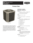
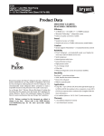
25HBA3
BasetSeries 13 Heat Pump
with Puronr Refrigerant
Product Data
INDUSTRY LEADING
FEATURES / BENEFITS
Efficiency
S 13 SEER/ 10.1 -- 10.8 EER/ 7.7 -- 8.3 HSPF (nominal)
S Microtube Technologyt refrigeration system
S Indoor air quality accessories available
Sound
S Sound level as low as 74 dBA
Comfort
S System supports Thermidistatt or standard thermostat
controls
Reliability
S Puronr refrigerant -- environmentally sound, won’t
deplete the ozone layer and low lifetime service cost.
A04030
the environmentally sound refrigerant
Carrier’s heat pumps with Puron r refrigerant provide a
collection of features unmatched by any other family of
equipment. The 25HBA has been designed utilizing Carrier’s
Puron refrigerant. The environmentally sound refrigerant allows
consumers to make a responsible decision in the protection of the
earth’s ozone layer.
As an Energy Starr Partner, Carrier Corporation has determined
that this product meets the Energy Starr guidelines for energy
efficiency. Refer to the combination ratings in the Product Data
for system combinations that meet Energy Starr guidelines.
S Front--seating service valves
S Scroll compressor
S Internal pressure relief valve
S Internal thermal overload
S High pressure switch
S Loss of charge switch
S Filter drier
S Balanced refrigeration system for maximum reliability
Durability
WeatherArmort protection package:
S Solid, Durable sheet metal construction
S Dense wire coil guard
S Baked--on, complete coverage, powder paint
Applications
S Long--line -- up to 250 ft. total equivalent length, up to
200 ft. condenser above evaporator, or up to 80 ft.
evaporator above condenser (See Longline Guide for
more information.)
S Low ambient (down to --20_F) with accessory kit
Warranty
S 5 year limited compressor warranty
S 5 year limited parts warranty
MODEL NUMBER NOMENCLATURE
1
N
2
N
3
A
4
A
5
A/N
6
N
7
N
8
N
9
A/N
10
A/N
11
A/N
12
N
13
N
2
5
H
B
A
3
3
6
A
0
0
3
0
Product
Series
Product
Family
Tier
Major
Series
SEER
Variations
Open
Open
Voltage
Minor
Series
25 = HP
H = RES HP
B=Base
A = Puron
A = Standard
0=Not
Defined
0=Not
Defined
3=208/230 ---1
Cooling
Capacity
3=13 SEER
0, 1, 2...
ISO 9001:2000
the environmentally sound refrigerant
25HBA3
REGISTERED
As an Energy Star® Partner, Carrier
Corporation has determined that this
product meets the ENERGY STAR®
guidelines for energy efficiency.
Refer to the combination ratings in
Product Data for system combinations that
meet Energy Star guidelines.
STANDARD FEATURES
Feature
18
24
30
36
42
48
60
Puron Refrigerant
X
X
X
X
X
X
X
13 SEER
X
X
X
X
X
X
X
Scroll Compressor
X
X
X
X
X
X
X
Dense Wire Coil Guard
X
X
X
X
X
X
X
Field Installed Filter Drier
X
X
X
X
X
X
X
Front Seating Service Valves
X
X
X
X
X
X
X
Internal Pressure Relief Valve
X
X
X
X
X
X
X
Internal Thermal Overload
X
X
X
X
X
X
X
Long Line capability
X
X
X
X
X
X
X
Low Ambient capability with Kit
X
X
X
X
X
X
X
Suction Line Accumulator
X
X
X
X
X
X
X
High Pressure Switch
X
X
X
X
X
X
X
Loss of Charge Switch
X
X
X
X
X
X
X
2
PHYSICAL DATA
18 ---30
146
169
24 ---30
162
189
30 ---30
203
235
5.25
5.9
2196
1/10
1100
2614
1/10
1100
36 ---30
42 ---30
207
246
239
278
Scroll
Puron® (R--- 410A)
TXV (Puron Hard Shutoff)
7.6
7.65
8.4
Propeller Type, Direct Drive
Vertical
2614
3365
3810
1/10
1/4
1/5
1100
1100
800
48 ---30
263
293
60 ---30
279
311
11.75
12.35
4046
1/5
800
4046
1/5
800
13.13
25
1
4
15.09
20
1
5
25.87
20
1
6
25.87
20
1
6
25.15
20
1
6
20.12
20
2
8
22.63
20
2
8
5/8
5/8
3/4
3/4
3/8
7/8
7/8
7/8
5/8
5/8
3/4
3/4
3/8
7/8
7/8
1--- 1/8
25HBA3
UNIT SIZE SERIES
Operating Weight (lb)
Shipping Weight (lb)
Compressor Type
REFRIGERANT
Control
Charge (lb)
COND FAN
Air Discharge
Air Qty. (CFM)
Motor HP
Motor RPM
COND COIL
Face Area (Sq. ft.)
Fins per In.
Rows
Circuits
VALVE CONNECT. (In. ID)
Vapor
Liquid
REFRIGERANT TUBES* (In. OD)
Vapor (0 ---80 ft. Tube Length)
Liquid (0 ---80 ft. Tube Length)
* For tubing sets between 80 and 200 ft. horizontal or 20 ft. vertical differential, consult the Longline Guideline.
Note: See unit Installation Instruction for proper installation.
VAPOR LINE SIZING AND COOLING CAPACITY LOSS
PURON 1--STAGE HEAT PUMP APPLICATIONS
LONG LINE APPLICATION: An application is considered
”Long line” when the total equivalent tubing length exceeds 80
ft. or when there is more than 20 ft. vertical separation between
indoor and outdoor units. These applications require additional
accessories and system modifications for reliable system
operation. The maximum allowable total equivalent length is 250
ft. The maximum vertical separation is 200 ft. when outdoor unit
is above indoor unit, and 80 ft. when the outdoor unit is below
the indoor unit. Refer to Accessory Usage Guideline below for
required accessories. See Longline Application Guideline for
required piping and system modifications. Also, refer to the table
below for the acceptable vapor tube diameters based on the total
length to minimize the cooling capacity loss.
Acceptable
Vapor Line
Diameters
(In. OD)
25
50
80
80+
100
125
150
175
200
225
250
18000
1 ---Stage Puron HP
1/2
1
2
3
3
4
6
7
8
9
10
12
5/8
0
0
1
1
1
1
2
2
3
3
3
24000
1 ---Stage Puron HP
5/8
0
1
1
1
2
3
3
4
4
5
6
3/4
0
0
0
0
0
1
1
1
1
1
2
5/8
1
2
3
3
3
4
5
6
7
8
9
3/4
0
0
1
1
1
1
2
2
2
3
3
7/8
0
0
0
0
0
1
1
1
1
1
1
5/8
1
2
4
4
5
6
7
9
10
11
13
3/4
0
0
1
1
1
2
2
3
3
4
4
7/8
0
0
0
0
0
1
1
1
1
2
2
42000
1 ---Stage Puron HP
3/4
0
1
2
2
2
3
4
4
5
6
6
7/8
0
0
1
1
1
1
2
2
2
3
3
48000
1 ---Stage Puron HP
3/4
0
1
2
2
3
4
5
5
6
7
8
7/8
0
0
1
1
1
2
2
2
3
3
4
3/4
1
2
4
4
5
6
7
9
10
11
12
7/8
0
1
2
2
2
3
4
4
5
5
6
1 1/8
0
0
0
0
1
1
1
1
1
1
2
Unit Nominal Size (Btuh)
30000
1 ---Stage Puron HP
36000
1 ---Stage Puron HP
60000
1 ---Stage Puron HP
Cooling Capacity Loss (%)Total Equivalent Line Length (ft.)
Standard Application
Long Line Application Requires Accessories
Standard Length = 80 ft. or less total equivalent length
Applications in this area are long line. Accessories are required as shown recommended on Long Line Application Guidelines
Applications in this area may have height restrictions that limit allowable total equivalent length, when outdoor unit is below indoor unit See
Long Line Application Guidelines
3
ACCESSORIES
25HBA3
ORDER NUMBER
HC34GE239
HC34GE240
HC38GE228
HC40GE226
HC40GE228
KAACH1201AAA
KAACH1401AAA
KSACY0101AAA
KAAFT0101AAA
KSAHS1701AAA
KHAIR0101AAA
KSALA0301410
KSALA0601AAA
KHAOT0201SEC
KHAOT0301FST
KHALS0401LLS
KSASH0601COP
KSASH2101COP
KAACS0201PTC
KSASF0101AAA
KAATD0101TDR
KSATX0201PUR
KSATX0301PUR
KSATX0401PUR
KSATX0501PUR
DESCRIPTION
18 ---30
BALL BEARING MOTOR
BALL BEARING MOTOR
BALL BEARING MOTOR
BALL BEARING MOTOR
BALL BEARING MOTOR
CRANKCASE HTR
CRANKCASE HTR
CYCLE PROTECTOR
FREEZE THERMOSTAT
HARD START
ISOLATION RELAY
LOW AMBIENT PSW
MOTORMASTER 230V
OUTDOOR THERMOSTAT
OUTDOOR THERMOSTAT
SOLENOID VALVE
SOUND BLKT
SOUND BLKT
START ASSIST PTC
SUPPORT FEET
TIME DELAY RELAY
TXV PURON HSO
TXV PURON HSO
TXV PURON HSO
TXV PURON HSO
24 ---30
30 ---30
X
X
36 ---30
42 ---30
48 ---30
60 ---30
X
X
S
X
S
X
X
X
X
X
X
X
X
X
X
X
X
X
X
X
X
X
X
X
X
X
X
X
X
X
X
X
X
X
X
X
X
X
X
X
X
X
X
X
X
X
X
X
X
X
X
X
X
X
X
X
X
X
X
X
X
X
X
X
X
X
X
X
X
X
X
X
X
X
X
X
X
X
X
X
X
X
X
X
X
X
X
X
X
X
X
X
X
X
X
X
X
X
X
X
X
X
X
X
X
X
X
X
X
X
x = Accessory S = Standard
ACCESSORY THERMOSTATS
THERMOSTAT / SUBBASE
PKG.
TSTATCCPRH01--- B*
TSTATCCPHH01--- B*
TSTATCCPHP01--- B
TSTATCCNHP01--- C
TSTATCCSHP01
TSTATCCBHP01--- B*
TSTATXXSEN01--- B**
TSTATXXNBP01
TSTATXXPBP01
TSTATXXSBP01
TSTATXXBBP01
TSTATXXCNV10{
DESCRIPTION
Thermidistatt Control — Non--- Programmable/Programmable Thermostat with Humidity Control (For use in
Dual Fuel, AC, HP, and 2S applications. Includes Outdoor Air Temperature Sensor.)
Hybrid Heatt (Dual Fuel) Thermostat — Auto Changeover, 7--- Day Programmable, °F/°C, Includes Outdoor
Sensor (TSTATXXSEN01--- B)
Thermostat — Auto Changeover, 7--- Day Programmable, °F/°C, 2--- Stage Heat, 1--- Stage Cool
Thermostat — Auto Changeover, Non--- Programmable, °F/°C, 2--- Stage Heat, 1--- Stage Cool
Standard Programmable Thermostat—Manual Changeover, 5--- 2 Day Programmable, °F/°C, 1--- Stage Heat/
1--- Stage Cool
Builder’s Thermostat — Heat Pump, Non--- Programmable, °F/°C, 2--- Stage Heat, 1--- Stage Cool, Manual
Changeover
Outdoor Air Temperature Sensor
Backplate for Non--- Programmable Thermostat
Backplate for Programmable Thermostat and Thermidistatt Control
Backplate for Standard Programmable Thermostat
Backplate for Builder’s Thermostat
Thermostat Conversion Kit (4 to 5 Wire) — 10 Pack
* Do not use in zoning heat pump applications.
** Outdoor temperature sensor is an accessory for all Carrier electronic thermostats, except the non ---programmable air conditioner version and builder;s
thermostats. It allows the temperature at a remote location (outdoors) to be displayed on the thermostat. The outdoor air temperature sensor must be used
with the dual fuel thermostat.
{ Thermostat conversion kit is a 24 ---vac accessory that can turn a 4 ---wire thermostat application into a 5 ---wire application. This kit can also be used to
replace a broken thermostat wire, or add an extra wire when needed.
The outdoor air temperature sensor is included with the Thermidistat Control and dual fuel thermostat.
4
ACCESSORY USAGE GUIDELINE
ACCESSORY
Yes
Yes
Standard
Yes
REQUIRED FOR
LONG LINE
APPLICATIONS*
(Over 80 Ft.)
Yes
No
Standard
Yes
REQUIRED FOR
SEA COAST
APPLICATIONS
(Within 2 miles)
No
No
Standard
No
REQUIRED FOR LOW---AMBIENT
COOLING APPLICATIONS (Below 55°
F)
Crankcase Heater
Evaporator Freeze Thermostat
Accumulator
Compressor Start Assist Capacitor and Relay
Motor Master® Control
or
Low---ambient Pressure Switch
Support Feet
Yes
No
No
Recommended
No
Ball Bearing Fan Motor
Yes{
No
See Long --- Line Application Guideline
No
Recommended
Liquid Line Solenoid Valve
No
No
* For tubing line sets between 80 and 200 ft. and/or 20 ft. vertical differential, refer to Residential Split---System Longline Application Guideline.
{ Required for Low ---Ambient Controller (full modulation feature) and MotorMasterr Control only.
6. Isolation Relay
An SPDT relay which switches the low--ambient controller out of
the outdoor fan motor circuit when the heat pump switches to
heating mode.
Usage Guideline:
Required in all heat pumps where low ambient kit has
been added.
7. Liquid--Line Solenoid Valve (LLS)
An electrically operated shutoff valve which stops and starts
refrigerant liquid flow in response to compressor operation. It is
to be installed at the outdoor unit to control refrigerant off cycle
migration in the heating mode.
Usage Guideline:
An LLS is required in all long line heat pump
applications to control refrigerant off cycle migration in
the heating mode. See Long Line Guideline.
8. Low--Ambient Pressure Switch Kit
A long life pressure switch which is mounted to outdoor unit
service valve. It is designed to cycle the outdoor fan motor in
order to maintain head pressure within normal operating limits.
The control will maintain working head pressure at low--ambient
temperatures down to 0_F when properly installed.
Usage Guideline:
A Low--Ambient Pressure Switch or MotorMasterr
Low--Ambient Controller must be used when cooling operation is
used at outdoor temperatures below 55_F (12.8_C).
9. MotorMasterr Low--Ambient Controller
A fan--speed control device activated by a temperature sensor,
designed to control condenser fan motor speed in response to the
saturated, condensing temperature during operation in cooling
mode only. For outdoor temperatures down to --20_F (--28.9_C),
it maintains condensing temperature at 100_F ±10_F (37.8_C ±
--12_C).
Usage Guideline:
A MotorMasterr Low Ambient Controller or
Low--Ambient Pressure Switch must be used when
cooling operation is used at outdoor temperatures
below 55_F (12.8_C).
Suggested for all commercial applications.
1. Ball--Bearing Fan Motor
A fan motor with ball bearings which permits speed reduction
while maintaining bearing lubrication.
Usage Guideline:
Required on all units when using MotorMasterr
2. Compressor Start Assist -- Capacitor and Relay
Start capacitor and relay gives a ”hard” boost to compressor
motor at each start up.
Usage Guideline:
Required for reciprocating compressors in the
following applications:
Long line
Low ambient cooling
Hard shut off expansion valve on indoor coil
Liquid line solenoid on indoor coil
Required for single--phase scroll compressors in the
following applications:
Long line
Low ambient cooling
Suggested for all compressors in areas with a history of
low voltage problems.
3. Compressor Start Assist — PTC Type
Solid state electrical device which gives a ”soft” boost to the
compressor at each start--up.
Usage Guideline:
Suggested in installations with marginal power supply.
4. Crankcase Heater
An electric resistance heater which mounts to the base of the
compressor to keep the lubricant warm during off cycles.
Improves compressor lubrication on restart and minimizes the
chance of liquid slugging.
Usage Guideline:
Required in low ambient cooling applications.
Required in long line applications.
Suggested in all commercial applications.
5. Evaporator Freeze Thermostat
An SPST temperature--actuated switch that stops unit operation
when evaporator reaches freeze--up conditions.
Usage Guideline:
Required when low ambient kit has been added.
5
25HBA3
Accessory Description and Usage (Listed Alphabetically)
25HBA3
Accessory Description and Usage (Listed Alphabetically) -- CONTINUED
10. Outdoor Air Temperature Sensor
Designed for use with Carrier Thermostats listed in this
publication. This device enables the thermostat to display the
outdoor temperature. This device also is required to enable
special thermostat features such as auxiliary heat lock out.
Usage Guideline:
Suggested for all Carrier thermostats listed in this
publication.
11. Outdoor Thermostat
An SPDT temperature--actuated switch which turns on
supplemental electric heaters when outdoor air temperature drops
below a user--selected set point.
Usage Guideline:
Electric supplemental heat applications in non--variable
speed indoor units when electric heat staging is desired.
12. Secondary Outdoor Thermostat
An SPDT temperature--actuated switch which turns on
third--stage of supplemental electric heaters when outdoor air
temperature drops below the second--stage set point.
Usage Guideline:
Outdoor thermostat applications where electric heater is
capable of 3--stage operation.
13. Sound Hood
Wraparound sound reducing cover for the compressor. Reduces
the sound level by about 2 dBA.
Usage Guideline:
Suggested when unit is installed closer than 15 ft. to
quiet areas, bedrooms, etc.
Suggested when unit is installed between two houses less
than 10 ft. apart.
14. Thermostatic Expansion Valve (TXV) Bi--Flow
A modulating flow--control valve which meters refrigerant liquid
flow rate into the evaporator in response to the superheat of the
refrigerant gas leaving the evaporator.
Usage Guideline:
Accessory required to meet ARI rating and system
reliability, where indoor not equipped.
Required in all heat pump applications designed with
Puron refrigerant.
15. Time--Delay Relay
An SPST delay relay which briefly continues operation of indoor
blower motor to provide additional cooling after the compressor
cycles off.
Note: Most indoor unit controls include this feature. For those
that do not, use the guideline below.
Usage Guideline:
Accessory required to meet ARI rating, where indoor
not equipped.
6
ELECTRICAL DATA
V/PH
OPER VOLTS*
MAX
MIN
COMPR
LRA
FAN
RLA
FLA
MCA
MIN WIRE
SIZE{
MIN
WIRE
SIZE{
MAX
LENGTH
(ft.)}
MAX
LENGTH
(ft.)}
60° C
75° C
60° C
75° C
MAX FUSE**
or CKT BRK
AMPS
18--- 30
48
9.0
0.75
12
14
14
66
62
20
24--- 30
58.3
12.8
0.75
16.8
14
14
47
45
25
30--- 30
77
14.1
0.75
21.4
12
12
58
56
30
79
16.7
1.4
22.2
12
12
56
54
35
42--- 30
109
19.9
1.2
26
10
10
77
73
40
48--- 30
117
21.8
1.2
35.4
8
8
88
84
50
60--- 30
134
26.3
1.2
34.1
8
8
91
87
50
36--- 30
208--- 230/1
253
197
* Permissible limits of the voltage range at which the unit will operate satisfactorily
{ If wire is applied at ambient greater than 30° C (86° F), consult table 310 ---16 of the NEC (ANSI/NFPA 70). The ampacity of non ---metallic---sheathed cable
(NM), trade name ROMEX, shall be that of 60° C (140° F) conditions, per the NEC (ANSI/NFPA 70) Article 336 ---26. If other than uncoated (no ---plated), 60
or 75° C (140 or 167° C) insulation, copper wire (solid wire for 10 AWG or smaller, stranded wire for larger than 10 AWG) is used, consult applicable tables
of the NEC (ANSI/NFPA 70).
} Length shown is as measured 1 way along wire path between unit and service panel for voltage drop not to exceed 2%.
** Time ---Delay fuse.
FLA --- Full Load Amps
LRA --- Locked Rotor Amps
MCA --- Minimum Circuit Amps
RLA --- Rated Load Amps
NOTE: Control circuit is 24 ---V on all units and requires external power source. Copper wire must be used from service disconnect to unit. All
motors/compressors contain internal overload protection.
A--WEIGHTED SOUND LEVEL (DBA)
UNIT SIZE
18--- 30
24--- 30
30--- 30
36--- 30
42--- 30
48--- 30
60--- 30
STANDARD
RATING
75
75
74
76
77
78
76
125
54
54.5
52
60
55.5
57
58.5
TYPICAL OCTAVE BAND SPECTRUM (without tone adjustment)
250
500
1000
2000
4000
63
68.5
71.5
68
63.5
64
69
69.5
67.5
64
62.5
66.5
68.5
65
63.5
64
69.5
70
68.5
65.5
60
63.5
71.5
65
62.5
64
68
74
67
63
63
68
70.5
66.5
64.5
8000
57
58
59
60.5
59
58.5
59.5
A--WEIGHTED SOUND LEVEL (DBA) WITH SOUND SHIELD
UNIT SIZE
18--- 30
24--- 30
30--- 30
36--- 30
42--- 30
48--- 30
60--- 30
STANDARD
RATING
74
74
74
76
75
75
75
125
53.5
54.0
51.5
58.5
55.0
57.5
58.5
TYPICAL OCTAVE BAND SPECTRUM (without tone adjustment)
250
500
1000
2000
4000
63.0
68.0
70.0
67.5
63.0
63.5
69.0
69.0
67.5
63.5
62.0
66.5
67.5
64.5
62.0
63.5
69.5
70.5
69.0
65.5
60.5
63.5
69.0
64.5
61.5
63.0
67.5
71.5
65.5
60.5
62.5
67.5
69.0
64.5
61.5
CHARGING SUBCOOLING (TXV--TYPE EXPANSION DEVICE)
UNIT SIZE ---SERIES
18--- 30
24--- 30
30--- 30
36--- 30
42--- 30
48--- 30
60--- 30
REQUIRED SUBCOOLING (_F)
10
12
11
10
11
11
12
7
8000
56.5
57.5
57.5
60.5
56.0
54.5
56.0
25HBA3
UNIT SIZE
8
0
0
0
0
0
0
0
25HBA318
25HBA324
25HBA330
25HBA336
25HBA342
25HBA348
25HBA360
18
24, 30, 36
42, 48, 60
UNIT SIZE
SERIES
UNIT
MINIMUM MOUNTING
PAD DIMENSIONS
26” X 26”
31 1/2” X 31 1/2”
35” X 35”
0
0
0
X
0
0
0
0
0
0
208--- 230--- 1--- 60
0
0
0
0
0
0
230--- 1--- 60
0
0
0
0
0
0
ELECTRICAL
CHARACTERISTICS
208/230--- 3--- 60
X
X
X
X
X
X
DIMENSIONS
460--- 3--- 60
28 15/16”
45 15/16”
45 15/16”
39 1/8”
32 5/16”
35 3/4”
31 3/16”
31 3/16”
35”
35”
35”
X = YES
0 = NO
3 3/4”
31 13/16”
25 3/4”
31 3/16”
3 7/8”
3 7/8”
3 7/8”
3 3/4”
3 3/4”
3 3/4”
C
B
A
7/8”
7/8”
7/8”
3/4”
3/4”
5/8”
5/8”
D
6 9/16”
6 9/16”
6 9/16”
6 9/16”
6 9/16”
6 9/16”
4 7/16”
E
28 7/16”
28 7/16”
28 7/16”
24 11/16”
24 11/16”
24 11/16”
21 1/4”
F
9 1/8”
9 1/8”
9 1/8”
9 1/8”
9 1/8”
9 1/8”
9 1/8”
G
1 1/8”
1 1/8”
1 1/8”
1 1/8”
1 1/8”
1 1/8”
1 1/8”
H
2 15/16”
2 15/16”
2 15/16”
2 13/16”
2 13/16”
2 13/16”
2 13/16”
K
5/8”
5/8”
5/8”
1/2”
1/2”
1/2”
1/2”
L
19”
19”
17 1/4”
17”
20 1/4”
15 5/8”
10 1/4”
M
19”
19”
19 1/8”
14 3/4”
17 3/8”
16 3/4”
10 3/4”
N
19”
14 1/2”
15 3/4”
20 3/8”
18 3/4”
14 1/2”
14”
P
4. Center of gravity
3. Series designation is the 13th position of the unit model number.
2. Minimum outdoor operating ambient in cooling mode is 55 _F, max. 125_ F .
on remaining side, and 24” between units for proper airflow.
1. Allow 30” clearance to service side of unit, 48” above unit, 6” on one side, 12”
3 13/16”
3 13/16”
3 13/16”
3 13/16”
3 13/16”
3 13/16”
3 13/16”
J
25HBA3
9
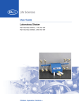
BUILDING HEAT LOSS, UNIT INTEGRATED
HEATING CAPACITY, MBTUH
0
10
20
30
40
50
60
70
80
--10
0
10
20
40
OUTDOOR TEMPERATURE, ºF
30
50
25HBA3 BALANCE POINT WORKSHEET
CFM
25HBA3
60
70
BASED ON INDOOR ENT. AIR AT 70 ºF AND AT RATED
FY4ANF018
25HBA318A
FY4ANF024
25HBA324A
25HBA330A
FY4ANF030
FY4ANF042
25HBA336A
25HBA342A
FY4ANF042
25HBA348A
25HBA348A
FY4ANF048
FY4ANB060
25HBA360A
80
A05007
0.0
2.9
5.9
8.8
11.7
14.6
17.6
20.5
23.4
kW
COMBINATION RATINGS
Unit
Size --Series
Indoor Model
Cooling
Capacity
Factory
Enhance
Standard
Rating
17,100
17,100
17,400
17,700
17,500
17,700
17,200
TDR&TXV
TDR&TXV
TDR&TXV
TDR&TXV
TDR&TXV
TDR&TXV
TDR&TXV
13.00
13.00
13.20
14.00
14.00
14.00
13.00
CAP**1814A**
CAP**1814A**
17,000
17,000
TDR&TXV
TXV
14.00
CAP**2414A**
CAP**2414A**
17,300
17,400
TDR&TXV
TXV
14.00
CAP**2417A**
CAP**2417A**
CAP**2417A**
17,400
17,300
17,400
TDR&TXV
TDR&TXV
TXV
14.00
14.00
CNPF*2418A**
17,400
TXV
CNPH*2417A**
CNPH*2417A**
CNPH*2417A**
CNPH*2417A**
CNPH*2417A**
CNPH*2417A**
17,300
17,400
17,300
17,300
17,400
17,400
TDR&TXV
TDR&TXV
TDR&TXV
TDR&TXV
TDR&TXV
TXV
14.00
14.00
14.00
14.00
14.00
CNPV*1814A**
CNPV*1814A**
17,000
17,000
TDR&TXV
TXV
14.00
CNPV*2414A**
CNPV*2414A**
17,300
17,400
TDR&TXV
TXV
14.00
CNPV*2417A**
CNPV*2417A**
CNPV*2417A**
17,400
17,300
17,400
TDR&TXV
TDR&TXV
TXV
14.00
14.00
CSPH*2412A**
CSPH*2412A**
CSPH*2412A**
CSPH*2412A**
CSPH*2412A**
CSPH*2412A**
*FY4ANF024
FF1ENP024
FF1ENP030
FV4BNF002
FV4BNF003
FX4CNF024
FX4CNF030
FY4ANF030
17,300
17,300
17,300
17,300
17,300
17,400
22,600
22,800
22,800
23,200
23,400
23,000
23,400
23,000
TDR&TXV
TDR&TXV
TDR&TXV
TDR&TXV
TDR&TXV
TXV
TDR&TXV
TDR&TXV
TDR&TXV
TDR&TXV
TDR&TXV
TDR&TXV
TDR&TXV
TDR&TXV
14.00
14.00
14.00
14.00
14.00
CAP**2414A**
CAP**2414A**
22,600
22,800
TDR&TXV
TXV
14.00
CAP**2417A**
CAP**2417A**
CAP**2417A**
22,800
22,800
22,800
TDR&TXV
TDR&TXV
TXV
14.00
14.00
CAP**3014A**
CAP**3014A**
23,000
23,000
TDR&TXV
TXV
14.00
CAP**3017A**
CAP**3017A**
CAP**3017A**
23,000
23,000
23,000
TDR&TXV
TDR&TXV
TXV
14.00
14.00
CNPF*2418A**
22,800
TXV
CNPH*2417A**
See note on pg. 17
22,600
TDR&TXV
25HBA3
*FY4ANF018
FF1ENP018
FF1ENP024
FV4BNF002
FX4CNF018
FX4CNF024
FY4ANF024
18 ---30
24 ---30
ARI Standard Ratings
Heating
Cooling
SEER
TDR
10.50
10.50
10.70
12.00
11.70
12.00
10.50
High Temp
E
E
Capacity
COP
18,000
3.36
18,000
3.38
17,900
3.44
17,200
3.64
17,600
3.60
17,400
3.66
17,900
3.38
Low Temp
H
H
Capacity
COP
10,900
2.24
10,900
2.26
10,900
2.28
10,500
2.48
10,500
2.38
10,500
2.42
11,000
2.26
HSPF
Furnace Model
7.7
7.7
7.7
8.2
8.0
8.1
7.7
11.70
10.50
17,100
18,000
3.34
3.32
10,200
10,900
2.30
2.24
7.7
7.7
58CV(A,X)070---12
13.00
11.70
10.80
17,300
18,000
3.50
3.48
10,300
11,000
2.36
2.30
7.8
7.7
58CV(A,X)070---12
13.00
17,200
17,300
18,000
3.54
3.52
3.48
10,300
10,300
11,000
2.38
2.36
2.30
7.8
7.9
7.7
58CV(A,X)090---16
58MVB060---14
13.00
12.00
11.70
10.80
13.00
10.80
18,000
3.54
11,000
2.30
7.8
13.00
11.70
11.70
11.70
11.70
11.70
10.80
17,300
17,300
17,300
17,300
17,300
18,000
3.54
3.58
3.56
3.58
3.58
3.54
10,300
10,300
10,300
10,300
10,300
11,000
2.38
2.38
2.38
2.38
2.38
2.30
7.8
7.9
7.9
7.9
7.9
7.8
58CV(A,X)070---12
58CV(A,X)090---16
58MVB040---14
58MVB060---14
58MVB080---14
13.00
11.70
10.80
17,100
18,000
3.48
3.48
10,300
10,900
2.34
2.28
7.7
7.7
58CV(A,X)070---12
13.00
11.70
10.80
17,300
18,000
3.54
3.54
10,300
11,000
2.38
2.30
7.8
7.8
58CV(A,X)070---12
17,300
17,300
18,000
3.60
3.56
3.54
10,300
10,300
11,000
2.38
2.38
2.30
7.9
7.9
7.8
58CV(A,X)090---16
58MVB060---14
13.00
11.70
11.70
10.80
11.70
12.00
11.70
12.00
11.70
10.80
10.50
10.70
10.40
11.70
12.00
11.40
11.70
10.60
17,300
17,300
17,300
17,300
17,300
17,800
24,000
24,000
24,200
23,200
23,000
23,800
23,600
24,000
3.56
3.58
3.58
3.58
3.58
3.50
3.54
3.56
3.56
3.80
3.78
3.72
3.84
3.64
10,300
10,300
10,300
10,300
10,400
11,000
15,000
15,200
15,100
14,400
14,300
14,600
14,600
15,100
2.38
2.38
2.38
2.38
2.38
2.32
2.48
2.46
2.48
2.66
2.66
2.60
2.66
2.52
7.9
7.9
7.9
7.9
7.9
7.8
8.2
8.2
8.0
8.5
8.5
8.3
8.5
8.4
58CV(A,X)070---12
58CV(A,X)090---16
58MVB040---14
58MVB060---14
58MVB080---14
11.50
10.50
23,400
24,400
3.62
3.60
14,300
15,100
2.58
2.50
8.3
8.3
58CV(A,X)070---12
13.00
13.00
11.70
11.70
10.50
23,400
23,400
24,400
3.66
3.64
3.60
14,300
14,300
15,100
2.60
2.58
2.50
8.4
8.4
8.3
58CV(A,X)090---16
58MVB060---14
13.00
11.70
10.60
23,000
23,400
3.64
3.56
14,400
15,200
2.60
2.52
8.4
8.3
58CV(A,X)070---12
13.00
11.70
11.70
10.60
23,000
23,000
23,400
3.68
3.68
3.56
14,300
14,300
15,200
2.62
2.62
2.52
8.5
8.5
8.3
58CV(A,X)090---16
58MVB060---14
13.00
10.50
24,400
3.68
15,200
2.52
8.5
11.50
23,600
3.68
14,400
2.58
8.4
13.00
13.00
13.00
13.00
14.00
14.00
14.00
14.00
13.20
14.00
EER
10
58CV(A,X)070---12
COMBINATION RATINGS CONTINUED
Indoor Model
Cooling
Capacity
Factory
Enhance
Standard
Rating
CNPH*2417A**
CNPH*2417A**
CNPH*2417A**
CNPH*2417A**
CNPH*2417A**
CNPH*2417A**
CNPH*2417A**
CNPH*2417A**
CNPH*2417A**
CNPH*2417A**
CNPH*2417A**
22,800
22,800
22,800
22,800
22,800
22,800
22,800
22,800
22,800
22,600
22,800
TDR&TXV
TDR&TXV
TDR&TXV
TDR&TXV
TDR&TXV
TDR&TXV
TDR&TXV
TDR&TXV
TDR&TXV
TDR&TXV
TXV
14.00
14.00
14.00
14.00
14.00
14.00
14.00
14.00
14.00
14.00
CNPH*3017A**
CNPH*3017A**
CNPH*3017A**
CNPH*3017A**
CNPH*3017A**
CNPH*3017A**
CNPH*3017A**
CNPH*3017A**
CNPH*3017A**
CNPH*3017A**
CNPH*3017A**
CNPH*3017A**
23,000
23,000
23,000
2,300
23,000
23,000
23,000
23,000
23,000
23,000
23,000
23,000
TDR&TXV
TDR&TXV
TDR&TXV
TDR&TXV
TDR&TXV
TDR&TXV
TDR&TXV
TDR&TXV
TDR&TXV
TDR&TXV
TDR&TXV
TXV
14.00
14.00
14.00
14.00
14.00
14.00
14.00
14.00
14.00
14.00
14.00
CNPV*2414A**
CNPV*2414A**
22,600
22,800
TDR&TXV
TXV
14.00
CNPV*2417A**
CNPV*2417A**
CNPV*2417A**
22,800
22,800
22,800
TDR&TXV
TDR&TXV
TXV
14.00
14.00
CNPV*3014A**
CNPV*3014A**
23,000
23,000
TDR&TXV
TXV
14.00
CNPV*3017A**
CNPV*3017A**
CNPV*3017A**
23,000
23,000
23,000
TDR&TXV
TDR&TXV
TXV
14.00
14.00
CSPH*2412A**
CSPH*2412A**
CSPH*2412A**
CSPH*2412A**
CSPH*2412A**
CSPH*2412A**
CSPH*2412A**
CSPH*2412A**
CSPH*2412A**
CSPH*2412A**
CSPH*2412A**
CSPH*2412A**
22,600
22,600
22,600
22,600
22,600
22,600
22,600
22,600
22,600
22,600
22,600
22,800
TDR&TXV
TDR&TXV
TDR&TXV
TDR&TXV
TDR&TXV
TDR&TXV
TDR&TXV
TDR&TXV
TDR&TXV
TDR&TXV
TDR&TXV
TXV
14.00
14.00
14.00
14.00
14.00
14.00
14.00
14.00
14.00
14.00
14.00
CSPH*3012A**
CSPH*3012A**
CSPH*3012A**
CSPH*3012A**
CSPH*3012A**
CSPH*3012A**
CSPH*3012A**
CSPH*3012A**
CSPH*3012A**
CSPH*3012A**
CSPH*3012A**
CSPH*3012A**
*FY4ANF030
FF1ENP030
FF1ENP036
30 ---30
FV4BNF002
FV4BNF003
FV4BNF005
FX4CN(B,F)036
See note on pg. 17
23,000
23,000
23,000
23,000
23,000
23,000
23,000
23,000
23,000
23,000
23,000
23,000
29,200
29,000
29,600
29,600
29,800
30,600
30,000
TDR&TXV
TDR&TXV
TDR&TXV
TDR&TXV
TDR&TXV
TDR&TXV
TDR&TXV
TDR&TXV
TDR&TXV
TDR&TXV
TDR&TXV
TXV
TDR&TXV
TDR&TXV
TDR&TXV
TDR&TXV
TDR&TXV
TDR&TXV
TDR&TXV
14.00
14.00
14.00
14.00
14.00
14.00
14.00
14.00
14.00
14.00
14.00
24 ---30
ARI Standard Ratings
Heating
High Temp
Low Temp
E
E
H
H
Capacity
COP
Capacity
COP
23,600
3.72
14,400
2.62
23,600
3.70
14,400
2.60
23,600
3.70
14,400
2.60
23,600
3.72
14,400
2.60
23,600
3.70
14,400
2.60
23,600
3.70
14,400
2.60
23,600
3.70
14,400
2.60
23,600
3.70
14,400
2.60
23,600
3.72
14,400
2.60
23,600
3.66
14,400
2.58
24,400
3.68
15,200
2.52
Cooling
13.00
13.00
13.00
14.00
14.00
14.00
14.00
SEER
TDR
EER
HSPF
Furnace Model
13.00
11.60
11.50
11.50
11.50
11.50
11.50
11.50
11.50
11.50
11.50
10.50
23,000
23,000
23,000
23,000
23,000
23,000
23,000
23,000
23,000
23,000
23,000
23,400
3.66
3.70
3.70
3.70
3.70
3.68
3.68
3.68
3.68
3.70
3.66
3.56
14,300
14,300
14,400
14,400
14,300
14,400
14,300
14,400
14,400
14,400
14,300
15,200
2.60
2.62
2.62
2.62
2.64
2.62
2.62
2.62
2.62
2.62
2.60
2.52
8.5
8.5
8.5
8.5
8.5
8.5
8.5
8.7
8.5
8.5
8.5
8.3
58CV(A,X)070---12
58CV(A,X)090---16
58CV(A,X)110---20
58CV(A,X)135---22
58CV(A,X)155---22
58MVB040---14
58MVB060---14
58MVB080---14
58MVB080---20
58MVB100---20
58MVB120---20
13.00
11.70
11.70
11.70
11.70
11.70
11.70
11.70
11.70
11.70
11.70
11.70
10.60
11.50
10.50
23,400
24,400
3.68
3.68
14,400
15,200
2.58
2.52
8.4
8.5
58CV(A,X)070---12
13.00
23,400
23,400
24,400
3.72
3.70
3.68
14,400
14,400
15,200
2.62
2.60
2.52
8.5
8.5
8.5
58CV(A,X)090---16
58MVB060---14
13.00
11.50
11.50
10.50
11.70
10.60
23,000
23,400
3.66
3.56
14,400
15,200
2.60
2.52
8.4
8.3
58CV(A,X)070---12
13.00
23,000
23,000
23,400
3.70
3.68
3.56
14,300
14,300
15,200
2.62
2.62
2.52
8.5
8.5
8.3
58CV(A,X)090---16
58MVB060---14
13.00
11.70
11.70
10.60
13.00
11.60
11.70
11.50
11.70
11.70
11.50
11.70
11.50
11.60
11.70
11.50
10.60
23,400
23,400
23,400
23,400
23,400
23,400
23,400
23,400
23,400
23,400
23,400
24,200
3.70
3.74
3.72
3.74
3.74
3.72
3.72
3.74
3.72
3.74
3.70
3.68
14,400
14,400
14,500
14,500
14,400
14,500
14,400
14,500
14,400
14,500
14,400
15,200
2.60
2.62
2.60
2.60
2.62
2.60
2.60
2.60
2.60
2.62
2.58
2.54
8.5
8.6
8.5
8.6
8.6
8.5
8.5
8.5
8.5
8.6
8.5
8.5
58CV(A,X)070---12
58CV(A,X)090---16
58CV(A,X)110---20
58CV(A,X)135---22
58CV(A,X)155---22
58MVB040---14
58MVB060---14
58MVB080---14
58MVB080---20
58MVB100---20
58MVB120---20
11.70
11.70
11.70
11.70
11.70
11.70
11.70
11.70
11.70
11.70
11.70
10.60
10.10
10.00
10.20
11.00
11.20
11.60
10.90
22,800
22,800
22,800
22,800
22,800
22,800
22,800
22,800
22,800
22,800
22,800
23,200
31,800
31,800
32,000
31,000
30,800
30,800
31,600
3.64
3.68
3.68
3.68
3.68
3.66
3.66
3.66
3.66
3.68
3.64
3.56
3.46
3.42
3.48
3.56
3.56
3.80
3.64
14,400
14,400
14,400
14,400
14,400
14,400
14,400
14,400
14,400
14,400
14,400
15,200
21,200
21,200
21,400
20,600
20,400
20,600
21,000
2.60
2.62
2.62
2.62
2.62
2.60
2.60
2.60
2.60
2.62
2.60
2.52
2.56
2.54
2.58
2.66
2.68
2.78
2.68
8.4
8.5
8.5
8.5
8.5
8.5
8.5
8.5
8.5
8.5
8.4
8.3
8.3
8.2
8.3
8.4
8.5
8.9
8.6
58CV(A,X)070---12
58CV(A,X)090---16
58CV(A,X)110---20
58CV(A,X)135---22
58CV(A,X)155---22
58MVB040---14
58MVB060---14
58MVB080---14
58MVB080---20
58MVB100---20
58MVB120---20
13.00
11
8.5
8.5
8.5
8.5
8.5
8.5
8.5
8.5
8.5
8.4
8.5
58CV(A,X)090---16
58CV(A,X)110---20
58CV(A,X)135---22
58CV(A,X)155---22
58MVB040---14
58MVB060---14
58MVB080---14
58MVB080---20
58MVB100---20
58MVB120---20
25HBA3
Unit
Size --Series
COMBINATION RATINGS CONTINUED
Indoor Model
Cooling
Capacity
Factory
Enhance
Standard
Rating
CSPH*3012A**
CSPH*3012A**
CSPH*3012A**
CSPH*3012A**
CSPH*3012A**
CSPH*3012A**
CSPH*3012A**
CSPH*3012A**
CSPH*3012A**
29,200
29,200
29,200
29,200
29,200
29,200
29,200
29,200
29,600
TDR&TXV
TDR&TXV
TDR&TXV
TDR&TXV
TDR&TXV
TDR&TXV
TDR&TXV
TDR&TXV
TXV
14.00
14.00
13.50
14.00
13.50
14.00
14.00
14.00
CSPH*3612A**
CSPH*3612A**
CSPH*3612A**
CSPH*3612A**
CSPH*3612A**
CSPH*3612A**
CSPH*3612A**
CSPH*3612A**
CSPH*3612A**
CSPH*3612A**
CSPH*3612A**
CSPH*3612A**
*FY4ANF042
FF1ENP036
FV4BNF002
FV4BNF003
FV4BNF005
FX4CN(B,F)036
FX4CN(B,F)042
FY4ANF036
29,400
29,400
29,400
29,400
29,400
29,400
29,400
29,400
29,400
29,400
29,400
29,600
34,000
33,600
33,400
33,800
35,000
34,000
34,800
33,000
TDR&TXV
TDR&TXV
TDR&TXV
TDR&TXV
TDR&TXV
TDR&TXV
TDR&TXV
TDR&TXV
TDR&TXV
TDR&TXV
TDR&TXV
TXV
TDR&TXV
TDR&TXV
TDR&TXV
TDR&TXV
TDR&TXV
TDR&TXV
TDR&TXV
TDR&TXV
14.00
14.00
14.00
14.00
14.00
14.00
14.00
14.00
14.00
14.00
14.00
CAP**3614A**
CAP**3614A**
32,400
32,400
TDR&TXV
TXV
13.50
CAP**3617A**
CAP**3617A**
CAP**3617A**
33,400
33,400
33,400
TDR&TXV
TDR&TXV
TXV
14.00
13.50
CAP**3621A**
CAP**3621A**
CAP**3621A**
CAP**3621A**
CAP**3621A**
33,600
33,200
33,400
33,400
33,400
TDR&TXV
TDR&TXV
TDR&TXV
TDR&TXV
TXV
14.00
13.50
13.50
14.00
CAP**4221A**
CAP**4221A**
CAP**4221A**
CAP**4221A**
CAP**4221A**
33,800
33,400
33,600
33,600
33,800
TDR&TXV
TDR&TXV
TDR&TXV
TDR&TXV
TXV
14.00
13.50
14.00
14.00
CAP**4224A**
CAP**4224A**
CAP**4224A**
CAP**4224A**
CAP**4224A**
33,800
33,800
33,600
33,600
33,800
TDR&TXV
TDR&TXV
TDR&TXV
TDR&TXV
TXV
14.00
14.00
13.50
14.00
CNPF*3618A**
33,400
TXV
CNPH*3617A**
CNPH*3617A**
CNPH*3617A**
CNPH*3617A**
CNPH*3617A**
CNPH*3617A**
CNPH*3617A**
CNPH*3617A**
CNPH*3617A**
CNPH*3617A**
CNPH*3617A**
See note on pg. 17
33,200
33,400
33,400
33,400
33,400
33,200
33,200
33,000
33,200
33,200
33,200
TDR&TXV
TDR&TXV
TDR&TXV
TDR&TXV
TDR&TXV
TDR&TXV
TDR&TXV
TDR&TXV
TDR&TXV
TDR&TXV
TDR&TXV
30 ---30
36 ---30
ARI Standard Ratings
Heating
High Temp
Low Temp
E
E
H
H
Capacity
COP
Capacity
COP
30,800
3.50
20,600
2.64
30,800
3.50
20,600
2.64
31,000
3.46
20,600
2.62
30,800
3.46
20,600
2.62
31,000
3.48
20,600
2.62
31,000
3.48
20,600
2.62
31,000
3.48
20,600
2.62
30,800
3.46
20,400
2.62
32,200
3.52
21,400
2.58
Cooling
SEER
TDR
13.00
11.00
11.00
10.80
10.90
10.80
10.90
10.90
11.00
10.20
HSPF
Furnace Model
8.3
8.3
8.3
8.3
8.3
8.3
8.3
8.3
8.4
58CV(A,X)135---22
58CV(A,X)155---22
58MVB040---14
58MVB060---14
58MVB080---14
58MVB080---20
58MVB100---20
58MVB120---20
11.10
11.20
11.20
11.30
11.30
11.10
11.10
11.10
11.10
11.20
11.20
10.30
10.60
10.70
11.20
11.50
12.00
11.20
11.50
10.50
30,800
31,000
30,800
31,000
31,000
30,800
30,800
30,800
30,800
31,000
31,000
32,000
35,800
35,400
34,800
34,400
33,800
35,200
35,200
35,200
3.58
3.60
3.62
3.62
3.64
3.58
3.58
3.60
3.58
3.60
3.58
3.64
3.56
3.44
3.54
3.56
3.76
3.62
3.76
3.36
20,600
20,600
20,600
20,600
20,600
20,600
20,600
20,600
20,600
20,600
20,600
21,600
22,200
21,800
21,200
20,800
21,000
21,400
21,600
21,600
2.68
2.70
2.70
2.70
2.70
2.66
2.68
2.68
2.68
2.68
2.68
2.64
2.42
2.40
2.46
2.50
2.58
2.50
2.54
2.34
8.5
8.5
8.6
8.6
8.6
8.5
8.5
8.5
8.5
8.5
8.5
8.6
8.1
7.9
8.1
8.1
8.6
8.3
8.5
7.7
58CV(A,X)070---12
58CV(A,X)090---16
58CV(A,X)110---20
58CV(A,X)135---22
58CV(A,X)155---22
58MVB040---14
58MVB060---14
58MVB080---14
58MVB080---20
58MVB100---20
58MVB120---20
11.00
10.50
34,600
35,200
3.44
3.40
21,000
21,800
2.42
2.38
7.9
7.8
58CV(A,X)070---12
13.00
34,400
34,400
35,600
3.48
3.46
3.46
21,000
21,000
22,000
2.46
2.44
2.40
8.0
7.9
7.9
58CV(A,X)090---16
58MVB060---14
13.00
11.50
11.20
10.50
34,400
34,400
34,400
34,400
35,600
3.50
3.44
3.48
3.48
3.46
21,000
21,000
21,000
21,000
22,000
2.46
2.42
2.44
2.46
2.40
8.0
7.9
8.0
8.0
7.9
58CV(A,X)110---20
58MVB080---14
58MVB080---20
58MVB100---20
13.00
11.50
11.20
11.30
11.40
10.50
34,600
34,600
34,600
34,600
35,800
3.56
3.48
3.52
3.54
3.52
21,000
21,000
21,000
21,000
22,000
2.48
2.44
2.46
2.46
2.42
8.1
8.0
8.0
8.1
8.0
58CV(A,X)110---20
58MVB080---14
58MVB080---20
58MVB100---20
13.00
11.50
11.20
11.50
11.50
10.60
34,400
34,400
34,600
34,400
35,800
3.58
3.60
3.50
3.54
3.52
20,800
20,800
21,000
21,000
22,000
2.50
2.52
2.44
2.48
2.42
8.1
8.2
8.0
8.1
8.0
58CV(A,X)135---22
58CV(A,X)155---22
58MVB040---14
58MVB120---20
13.00
11.50
11.70
11.20
11.50
10.60
13.00
10.50
35,600
3.44
22,000
2.38
7.9
11.20
11.20
11.20
11.20
11.50
11.10
11.20
11.00
11.20
11.20
11.20
34,400
34,400
34,400
34,400
34,400
34,400
34,400
34,400
34,400
34,400
34,400
3.42
3.46
3.46
3.46
3.48
3.42
3.44
3.40
3.44
3.44
3.44
21,000
21,000
21,000
21,000
21,000
21,200
21,000
21,200
21,000
21,000
21,000
2.42
2.44
2.44
2.44
2.46
2.40
2.42
2.40
2.42
2.44
2.42
7.9
7.9
8.0
8.0
8.0
7.8
7.9
7.8
7.9
7.9
7.9
13.00
13.00
13.00
13.50
14.00
14.00
13.50
14.00
13.00
13.50
13.50
13.50
13.50
14.00
13.50
13.50
13.50
13.50
13.50
13.50
EER
13
58CV(A,X)070---12
58CV(A,X)090---16
58CV(A,X)110---20
58CV(A,X)135---22
58CV(A,X)155---22
58MVB040---14
58MVB060---14
58MVB080---14
58MVB080---20
58MVB100---20
58MVB120---20
25HBA3
Unit
Size --Series
COMBINATION RATINGS CONTINUED
25HBA3
Unit
Size --Series
36 ---30
42 ---30
Indoor Model
Cooling
Capacity
Cooling
Factory
Enhance
Standard
Rating
CNPH*3617A**
33,400
TXV
CNPH*4221A**
CNPH*4221A**
CNPH*4221A**
CNPH*4221A**
CNPH*4221A**
CNPH*4221A**
CNPH*4221A**
CNPH*4221A**
CNPH*4221A**
CNPH*4221A**
CNPH*4221A**
CNPH*4221A**
33,600
33,600
33,800
33,800
33,800
33,400
33,600
33,400
33,600
33,600
33,600
33,800
TDR&TXV
TDR&TXV
TDR&TXV
TDR&TXV
TDR&TXV
TDR&TXV
TDR&TXV
TDR&TXV
TDR&TXV
TDR&TXV
TDR&TXV
TXV
14.00
14.00
14.00
14.00
14.00
14.00
14.00
14.00
14.00
14.00
14.00
CNPV*3617A**
CNPV*3617A**
CNPV*3617A**
33,400
33,200
33,400
TDR&TXV
TDR&TXV
TXV
13.50
13.50
CNPV*3621A**
CNPV*3621A**
CNPV*3621A**
CNPV*3621A**
CNPV*3621A**
33,600
33,200
33,200
33,400
33,400
TDR&TXV
TDR&TXV
TDR&TXV
TDR&TXV
TXV
13.50
13.50
13.50
13.50
CNPV*4221A**
CNPV*4221A**
CNPV*4221A**
CNPV*4221A**
CNPV*4221A**
33,800
33,400
33,600
33,600
33,800
TDR&TXV
TDR&TXV
TDR&TXV
TDR&TXV
TXV
14.00
14.00
14.00
14.00
CSPH*3612A**
CSPH*3612A**
CSPH*3612A**
CSPH*3612A**
CSPH*3612A**
CSPH*3612A**
CSPH*3612A**
CSPH*3612A**
CSPH*3612A**
CSPH*3612A**
CSPH*3612A**
CSPH*3612A**
33,400
33,400
33,400
33,400
33,400
33,400
33,400
33,400
33,400
33,400
33,400
33,400
TDR&TXV
TDR&TXV
TDR&TXV
TDR&TXV
TDR&TXV
TDR&TXV
TDR&TXV
TDR&TXV
TDR&TXV
TDR&TXV
TDR&TXV
TXV
14.00
14.00
14.00
14.00
14.00
13.50
14.00
13.50
14.00
14.00
14.00
CSPH*4212A**
CSPH*4212A**
CSPH*4212A**
CSPH*4212A**
CSPH*4212A**
CSPH*4212A**
CSPH*4212A**
CSPH*4212A**
CSPH*4212A**
CSPH*4212A**
CSPH*4212A**
CSPH*4212A**
*FY4ANF042
FV4BNB006
FV4BNF003
FV4BNF005
FX4BNF042
FX4BNF048
FX4CN(B,F)042
FX4CN(B,F)048
FY4ANF048
33,800
33,800
33,800
33,800
33,800
33,600
33,600
33,600
33,600
33,800
33,800
33,800
40,500
42,500
40,000
42,000
40,500
41,500
41,500
42,500
41,500
TDR&TXV
TDR&TXV
TDR&TXV
TDR&TXV
TDR&TXV
TDR&TXV
TDR&TXV
TDR&TXV
TDR&TXV
TDR&TXV
TDR&TXV
TXV
TDR&TXV
TDR&TXV
TDR&TXV
TDR&TXV
TDR&TXV
TDR&TXV
TDR&TXV
TDR&TXV
TDR&TXV
14.00
14.00
14.00
14.00
14.00
14.00
14.00
14.00
14.00
14.00
14.00
13.00
14.00
14.00
14.00
13.00
13.20
14.00
14.00
13.20
ARI Standard Ratings
Heating
High Temp
Low Temp
E
E
H
H
Capacity
COP
Capacity
COP
35,600
3.44
22,000
2.38
Furnace Model
SEER
TDR
EER
13.00
10.50
34,600
34,400
34,400
34,400
34,400
34,600
34,400
34,400
34,600
34,400
34,400
35,800
3.54
3.58
3.60
3.62
3.62
3.54
3.56
3.54
3.56
3.58
3.58
3.54
21,000
20,800
20,800
20,800
20,800
21,000
21,000
21,000
21,000
21,000
20,800
22,000
2.48
2.50
2.52
2.52
2.54
2.48
2.50
2.48
2.48
2.50
2.50
2.42
8.1
8.2
8.2
8.2
8.3
8.1
8.1
8.1
8.1
8.2
8.2
8.1
58CV(A,X)070---12
58CV(A,X)090---16
58CV(A,X)110---20
58CV(A,X)135---22
58CV(A,X)155---22
58MVB040---14
58MVB060---14
58MVB080---14
58MVB080---20
58MVB100---20
58MVB120---20
13.00
11.50
11.70
11.70
11.70
11.70
11.50
11.60
11.50
11.50
11.50
11.70
10.60
34,400
34,400
35,600
3.46
3.44
3.44
21,000
21,000
22,000
2.44
2.42
2.38
7.9
7.9
7.9
58CV(A,X)090---16
58MVB060---14
13.00
11.20
11.20
10.50
34,400
34,400
34,400
34,400
35,600
3.48
3.40
3.44
3.46
3.44
21,000
21,000
21,000
21,000
22,000
2.44
2.40
2.42
2.42
2.38
8.0
7.8
7.9
7.9
7.9
58CV(A,X)110---20
58MVB080---14
58MVB080---20
58MVB100---20
13.00
11.20
11.00
11.20
11.20
10.50
34,400
34,400
34,600
34,400
35,800
3.60
3.54
3.56
3.58
3.54
20,800
21,000
21,000
21,000
22,000
2.52
2.48
2.48
2.50
2.42
8.2
8.1
8.1
8.2
8.1
58CV(A,X)110---20
58MVB080---14
58MVB080---20
58MVB100---20
13.00
11.70
11.50
11.50
11.50
10.60
34,600
34,600
34,600
34,600
34,600
34,600
34,600
34,600
34,600
34,600
34,600
35,600
3.58
3.62
3.64
3.64
3.66
3.56
3.60
3.54
3.60
3.60
3.60
3.62
21,200
21,000
21,200
21,000
21,000
21,200
21,200
21,200
21,200
21,200
21,000
22,200
2.48
2.50
2.52
2.52
2.54
2.48
2.50
2.46
2.48
2.50
2.50
2.44
8.2
8.2
8.3
8.3
8.3
8.1
8.2
8.1
8.2
8.2
8.2
8.2
58CV(A,X)070---12
58CV(A,X)090---16
58CV(A,X)110---20
58CV(A,X)135---22
58CV(A,X)155---22
58MVB040---14
58MVB060---14
58MVB080---14
58MVB080---20
58MVB100---20
58MVB120---20
13.00
11.50
11.50
11.50
11.50
11.70
11.20
11.50
11.20
11.50
11.50
11.50
10.70
11.50
11.50
11.50
11.70
11.70
11.50
11.50
11.50
11.50
11.50
11.50
10.80
10.40
12.40
11.50
12.10
10.40
10.60
11.20
11.70
10.60
34,600
34,600
34,600
34,600
34,600
34,600
34,600
34,600
34,600
34,600
34,600
35,800
42,000
39,500
41,000
40,500
42,500
41,000
42,000
40,000
41,000
3.64
3.68
3.70
3.70
3.74
3.64
3.66
3.62
3.66
3.68
3.66
3.66
3.54
3.68
3.42
3.64
3.54
3.56
3.70
3.76
3.56
21,200
21,000
21,200
21,000
21,000
21,200
21,200
21,200
21,200
21,200
21,200
22,200
26,400
25,800
25,600
25,800
26,400
26,600
25,800
25,800
26,600
2.50
2.52
2.54
2.54
2.56
2.48
2.52
2.48
2.50
2.52
2.52
2.46
2.46
2.56
2.40
2.50
2.46
2.50
2.56
2.66
2.50
8.3
8.4
8.4
8.4
8.4
8.3
8.3
8.2
8.3
8.3
8.3
8.3
8.1
8.4
7.9
8.3
8.1
8.2
8.4
8.7
8.2
58CV(A,X)070---12
58CV(A,X)090---16
58CV(A,X)110---20
58CV(A,X)135---22
58CV(A,X)155---22
58MVB040---14
58MVB060---14
58MVB080---14
58MVB080---20
58MVB100---20
58MVB120---20
13.20
See note on pg. 17
14
HSPF
7.9
COMBINATION RATINGS CONTINUED
25HBA3
Unit
Size --Series
Indoor Model
Cooling
Capacity
Cooling
Factory
Enhance
Standard
Rating
CNPV*4824A**
CNPV*4824A**
CNPV*4824A**
40,500
40,500
41,000
TDR&TXV
TDR&TXV
TXV
13.50
14.00
CSPH*4212A**
CSPH*4212A**
CSPH*4212A**
CSPH*4212A**
CSPH*4212A**
CSPH*4212A**
CSPH*4212A**
CSPH*4212A**
CSPH*4212A**
CSPH*4212A**
CSPH*4212A**
CSPH*4212A**
39,500
40,000
40,000
40,000
40,000
39,500
40,000
39,500
40,000
40,000
40,000
40,000
TDR&TXV
TDR&TXV
TDR&TXV
TDR&TXV
TDR&TXV
TDR&TXV
TDR&TXV
TDR&TXV
TDR&TXV
TDR&TXV
TDR&TXV
TXV
13.50
14.00
14.00
14.00
14.00
13.50
14.00
13.50
14.00
14.00
14.00
CSPH*4812A**
CSPH*4812A**
CSPH*4812A**
CSPH*4812A**
CSPH*4812A**
CSPH*4812A**
CSPH*4812A**
CSPH*4812A**
CSPH*4812A**
CSPH*4812A**
CSPH*4812A**
CSPH*4812A**
*FY4ANF048
FV4BNB006
FV4BNF005
FX4BNB060
FX4BNF048
FX4CN(B,F)048
FX4CN(B,F)060
FY4ANB060
41,000
41,000
41,000
41,000
41,000
40,500
40,500
40,500
40,500
40,500
40,500
41,000
46,500
48,000
47,000
47,500
46,500
47,500
48,000
47,500
TDR&TXV
TDR&TXV
TDR&TXV
TDR&TXV
TDR&TXV
TDR&TXV
TDR&TXV
TDR&TXV
TDR&TXV
TDR&TXV
TDR&TXV
TXV
TDR&TXV
TDR&TXV
TDR&TXV
TDR&TXV
TDR&TXV
TDR&TXV
TDR&TXV
TDR&TXV
13.50
14.00
14.00
14.00
14.00
13.50
14.00
13.50
14.00
14.00
14.00
CAP**4817A**
CAP**4817A**
45,000
45,000
TDR&TXV
TXV
14.00
CAP**4821A**
CAP**4821A**
CAP**4821A**
CAP**4821A**
45,500
45,500
45,500
46,000
TDR&TXV
TDR&TXV
TDR&TXV
TXV
14.00
14.00
14.00
CAP**4824A**
CAP**4824A**
CAP**4824A**
CAP**4824A**
45,500
46,000
45,500
46,000
TDR&TXV
TDR&TXV
TDR&TXV
TXV
14.00
14.00
14.00
CAP**6021A**
CAP**6021A**
CAP**6021A**
CAP**6021A**
CAP**6024A**
CAP**6024A**
CAP**6024A**
CAP**6024A**
45,500
45,500
45,500
46,000
47,000
47,000
46,500
47,000
TDR&TXV
TDR&TXV
TDR&TXV
TXV
TDR&TXV
TDR&TXV
TDR&TXV
TXV
14.00
14.00
14.00
CNPF*4818A**
45,000
TXV
CNPH*4821A**
CNPH*4821A**
CNPH*4821A**
CNPH*4821A**
CNPH*4821A**
CNPH*4821A**
CNPH*4821A**
See note on pg. 17
44,500
44,500
45,000
45,000
44,500
44,500
44,500
TDR&TXV
TDR&TXV
TDR&TXV
TDR&TXV
TDR&TXV
TDR&TXV
TDR&TXV
42 ---30
48 ---30
SEER
TDR
HSPF
Furnace Model
13.00
11.20
11.40
10.60
41,500
41,000
41,000
41,000
41,000
41,500
41,500
41,500
41,500
41,500
41,500
42,500
3.60
3.66
3.66
3.70
3.68
3.58
3.62
3.58
3.62
3.64
3.62
3.66
25,600
25,400
25,400
25,200
25,200
25,600
25,400
25,600
25,600
25,400
25,400
26,400
2.52
2.56
2.58
2.60
2.60
2.52
2.54
2.52
2.54
2.56
2.56
2.52
8.2
8.4
8.4
8.4
8.4
8.2
8.3
8.2
8.3
8.3
8.3
8.3
58CV(A,X)070---12
58CV(A,X)090---16
58CV(A,X)110---20
58CV(A,X)135---22
58CV(A,X)155---22
58MVB040---14
58MVB060---14
58MVB080---14
58MVB080---20
58MVB100---20
58MVB120---20
13.00
11.10
11.40
11.40
11.50
11.60
11.10
11.30
11.10
11.20
11.30
11.40
10.70
11.10
11.40
11.40
11.60
11.60
11.20
11.30
11.10
11.30
11.30
11.40
10.70
10.8
12.50
12.20
11.20
11.10
11.70
12.00
11.00
41,500
41,000
41,000
41,000
41,000
41,500
41,000
41,500
41,000
41,000
41,000
42,000
48,500
46,000
47,500
45,000
48,500
47,500
44,000
45,000
3.64
3.70
3.70
3.74
3.72
3.62
3.66
3.62
3.66
3.68
3.68
3.68
3.60
3.86
3.78
3.52
3.60
3.78
3.74
3.52
25,600
25,400
25,400
25,400
25,200
25,600
25,400
25,600
25,600
25,400
25,400
26,400
30,800
29,400
29,400
30,800
30,800
30,000
30,000
30,800
2.54
2.58
2.58
2.60
2.60
2.52
2.56
2.52
2.56
2.56
2.56
2.52
2.58
2.78
2.72
2.62
2.58
2.70
2.76
2.62
8.3
8.4
8.5
8.5
8.5
8.3
8.4
8.3
8.4
8.4
8.4
8.4
8.3
8.8
8.6
8.4
8.3
8.6
8.7
8.4
58CV(A,X)070---12
58CV(A,X)090---16
58CV(A,X)110---20
58CV(A,X)135---22
58CV(A,X)155---22
58MVB040---14
58MVB060---14
58MVB080---14
58MVB080---20
58MVB100---20
58MVB120---20
11.50
10.80
47,500
48,000
3.70
3.66
29,800
30,200
2.62
2.60
8.4
8.4
58CV(A,X)090---16
13.00
48,000
48,500
48,000
49,000
3.68
3.62
3.64
3.68
29,600
29,800
29,600
30,400
2.62
2.58
2.60
2.60
8.4
8.3
8.3
8.4
58CV(A,X)110---20
58MVB080---20
58MVB100---20
13.00
11.50
11.50
11.50
10.80
48,000
48,000
48,000
49,000
3.70
3.74
3.64
3.68
29,400
29,400
29,600
30,400
2.64
2.66
2.60
2.60
8.5
8.5
8.3
8.4
58CV(A,X)135---22
58CV(A,X)155---22
58MVB120---20
13.00
11.70
11.50
11.50
10.80
46,000
46,000
46,000
45,000
46,000
46,000
46,000
45,000
3.68
3.64
3.66
3.50
3.70
3.72
3.64
3.50
29,600
29,800
29,600
30,600
29,600
29,400
29,600
30,600
2.66
2.62
2.64
2.62
2.68
2.68
2.64
2.62
8.5
8.4
8.4
8.3
8.5
8.6
8.4
8.3
58CV(A,X)110---20
58MVB080---20
58MVB100---20
13.00
11.70
11.70
11.70
10.80
11.70
12.00
11.70
10.80
13.00
10.80
48,500
3.50
30,000
2.54
8.1
11.50
11.50
11.70
11.70
11.50
11.50
11.50
48,000
48,000
48,000
48,000
48,500
48,000
48,000
3.62
3.64
3.68
3.70
3.60
3.62
3.62
29,600
29,600
29,400
29,400
29,600
29,600
29,600
2.60
2.62
2.64
2.66
2.60
2.60
2.60
8.3
8.4
8.4
8.5
8.3
8.3
8.3
13.00
13.00
14.00
14.00
13.00
13.00
14.00
14.00
13.50
13.00
14.00
14.00
14.00
14.00
14.00
14.00
14.00
14.00
14.00
14.00
EER
ARI Standard Ratings
Heating
High Temp
Low Temp
E
E
H
H
Capacity
COP
Capacity
COP
41,000
3.60
25,400
2.52
41,000
3.64
25,200
2.56
42,000
3.64
26,400
2.52
16
8.2
8.3
8.3
58MVB040---14
58MVB120---20
58CV(A,X)135---22
58CV(A,X)155---22
58MVB120---20
58CV(A,X)090---16
58CV(A,X)110---20
58CV(A,X)135---22
58CV(A,X)155---22
58MVB080---20
58MVB100---20
58MVB120---20
COMBINATION RATINGS CONTINUED
48 ---30
60 ---30
Indoor Model
Cooling
Capacity
ARI Standard Ratings
Heating
High Temp
Low Temp
E
E
H
H
Capacity
COP
Capacity
COP
49,000
3.68
30,400
2.60
Cooling
Factory
Enhance
Standard
Rating
CNPH*4821A**
45,000
TXV
CNPH*6024A**
CNPH*6024A**
CNPH*6024A**
CNPH*6024A**
CNPH*6024A**
CNPH*6024A**
CNPH*6024A**
CNPH*6024A**
46,500
46,500
46,500
47,000
46,500
46,500
46,500
47,000
TDR&TXV
TDR&TXV
TDR&TXV
TDR&TXV
TDR&TXV
TDR&TXV
TDR&TXV
TXV
14.00
14.00
14.00
14.00
14.00
14.00
14.00
CNPV*4821A**
CNPV*4821A**
CNPV*4821A**
CNPV*4821A**
45,500
45,500
45,500
46,000
TDR&TXV
TDR&TXV
TDR&TXV
TXV
14.00
14.00
14.00
CNPV*4824A**
CNPV*4824A**
CNPV*4824A**
CNPV*4824A**
45,500
46,000
45,500
46,000
TDR&TXV
TDR&TXV
TDR&TXV
TXV
14.00
14.00
14.00
CNPV*6024A**
CNPV*6024A**
CNPV*6024A**
CNPV*6024A**
46,500
47,000
46,500
47,000
TDR&TXV
TDR&TXV
TDR&TXV
TXV
14.00
14.00
14.00
CSPH*4812A**
CSPH*4812A**
CSPH*4812A**
CSPH*4812A**
CSPH*4812A**
CSPH*4812A**
CSPH*4812A**
CSPH*4812A**
45,500
45,500
45,500
45,500
45,500
45,500
45,500
46,000
TDR&TXV
TDR&TXV
TDR&TXV
TDR&TXV
TDR&TXV
TDR&TXV
TDR&TXV
TXV
14.00
14.00
14.00
14.00
14.00
14.00
14.00
CSPH*6012A**
CSPH*6012A**
CSPH*6012A**
CSPH*6012A**
CSPH*6012A**
CSPH*6012A**
CSPH*6012A**
CSPH*6012A**
*FY4ANB060
FV4BNB006
FX4CN(B,F)060
46,500
47,000
47,000
47,000
46,500
46,500
46,500
47,000
59,500
60,000
60,000
TDR&TXV
TDR&TXV
TDR&TXV
TDR&TXV
TDR&TXV
TDR&TXV
TDR&TXV
TXV
TDR&TXV
TDR&TXV
TDR&TXV
14.00
14.00
14.00
14.00
14.00
14.00
14.00
CAP**6021A**
CAP**6021A**
58,000
59,000
TDR&TXV
TXV
13.50
CAP**6024A**
CAP**6024A**
CAP**6024A**
59,000
59,000
60,000
TDR&TXV
TDR&TXV
TXV
13.50
14.00
CNPH*6024A**
CNPH*6024A**
CNPH*6024A**
CNPH*6024A**
58,500
58,500
59,000
59,500
TDR&TXV
TDR&TXV
TDR&TXV
TXV
13.50
13.50
14.00
CNPV*6024A**
CNPV*6024A**
CNPV*6024A**
58,500
59,000
59,500
TDR&TXV
TDR&TXV
TXV
13.50
14.00
13.00
14.00
14.00
Furnace Model
SEER
TDR
EER
13.00
10.80
13.00
11.70
11.70
12.00
12.00
11.50
11.70
11.70
10.80
46,000
46,000
46,000
46,000
46,000
46,000
46,000
45,000
3.68
3.70
3.74
3.76
3.66
3.68
3.68
3.66
29,600
29,600
29,400
29,400
29,800
29,600
29,600
30,600
2.64
2.66
2.68
2.68
2.62
2.64
2.64
2.62
8.4
8.5
8.5
8.6
8.4
8.4
8.4
8.5
58CV(A,X)090---16
58CV(A,X)110---20
58CV(A,X)135---22
58CV(A,X)155---22
58MVB080---20
58MVB100---20
58MVB120---20
13.00
11.50
11.50
11.50
10.80
48,000
48,500
48,000
49,000
3.64
3.60
3.62
3.68
29,600
29,600
29,600
30,400
2.62
2.60
2.60
2.60
8.4
8.3
8.3
8.4
58CV(A,X)110---20
58MVB080---20
58MVB100---20
13.00
11.70
11.50
11.50
10.80
48,000
48,000
48,000
49,000
3.68
3.70
3.62
3.68
29,400
29,400
29,600
30,400
2.64
2.66
2.60
2.60
8.4
8.5
8.3
8.4
58CV(A,X)135---22
58CV(A,X)155---22
58MVB120---20
13.00
12.00
12.00
11.70
10.80
46,000
46,000
46,000
45,000
3.74
3.76
3.68
3.66
29,400
29,400
29,600
30,600
2.68
2.68
2.64
2.62
8.5
8.6
8.4
8.5
58CV(A,X)135---22
58CV(A,X)155---22
58MVB120---20
13.00
11.50
11.50
11.70
11.70
11.50
11.50
11.50
10.80
48,000
48,000
48,000
48,000
48,500
48,000
48,000
49,000
3.68
3.70
3.72
3.76
3.66
3.68
3.66
3.72
29,800
29,600
29,600
29,400
29,800
29,800
29,600
30,600
2.62
2.62
2.64
2.66
2.60
2.62
2.62
2.62
8.4
8.4
8.5
8.6
8.4
8.4
8.4
8.5
58CV(A,X)090---16
58CV(A,X)110---20
58CV(A,X)135---22
58CV(A,X)155---22
58MVB080---20
58MVB100---20
58MVB120---20
11.70
11.70
12.00
12.00
11.70
11.70
11.70
10.80
10.8
11.50
12.00
46,000
46,000
46,000
46,000
46,000
46,000
46,000
45,000
60,000
58,500
58,500
3.74
3.76
3.78
3.80
3.70
3.72
3.72
3.68
3.62
3.74
3.74
29,600
29,600
29,600
29,400
29,800
29,800
29,600
30,600
38,500
36,200
36,200
2.66
2.68
2.70
2.70
2.64
2.66
2.66
2.64
2.56
2.68
2.68
8.5
8.6
8.6
8.7
8.5
8.5
8.5
8.5
8.0
8.2
8.3
58CV(A,X)090---16
58CV(A,X)110---20
58CV(A,X)135---22
58CV(A,X)155---22
58MVB080---20
58MVB100---20
58MVB120---20
13.00
11.20
10.80
56,500
58,000
3.48
3.48
36,000
36,400
2.52
2.52
7.8
7.8
58CV(A,X)110---20
13.00
11.50
11.50
10.80
57,500
57,500
59,000
3.50
3.54
3.60
35,800
35,800
37,000
2.54
2.56
2.54
7.8
7.9
8.0
58CV(A,X)135---22
58CV(A,X)155---22
13.00
11.20
11.20
11.50
10.80
57,500
57,000
57,000
58,500
3.46
3.48
3.52
3.54
36,000
35,800
35,800
37,600
2.52
2.54
2.56
2.60
7.7
7.8
7.8
8.0
58CV(A,X)110---20
58CV(A,X)135---22
58CV(A,X)155---22
13.00
11.20
11.50
10.80
57,000
57,000
58,500
3.48
3.52
3.54
35,800
35,800
36,800
2.54
2.56
2.54
7.8
7.8
7.9
58CV(A,X)135---22
58CV(A,X)155---22
13.00
HSPF
8.4
CSPH*6012A**
59,000
TDR&TXV
13.50
11.20
57,500
3.52
36,000
2.54
7.8
58CV(A,X)110---20
CSPH*6012A**
59,000
TDR&TXV
14.00
11.50
57,500
3.56
35,800
2.56
7.9
58CV(A,X)135---22
CSPH*6012A**
59,000
TDR&TXV
14.00
11.50
57,500
3.58
35,800
2.58
7.9
58CV(A,X)155---22
CSPH*6012A**
60,000
TXV
13.00
10.80
59,000
3.62
37,000
2.56
8.0
* Ratings are net values reflecting the effects of circulating fan heat. Supplemental electric heat is not included. Ratings are based on:
Cooling Standard: 80_F (27_C) db 67_F (19_C) wb indoor entering air temperature and 95_F (35_C) db air entering outdoor unit.
High---Temp Heating Standard: 70_F (21_C) db indoor entering air temperature and 47_F (8_C) db 43˚F (6_C) wb air entering outdoor unit.
Low ---Temp Heating Standard: 70_F (21_C) db indoor entering air temperature and 17_F (±9_C) db 15˚F (±10_C) wb air entering outdoor unit.
SEER — Seasonal Energy Efficiency Ratio
COP — Coefficient of Performance
TDR — Time---Delay Relay
HSPF — Heating Seasonal Performance Factor
EER — Energy Efficiency Ratio
17
25HBA3
Unit
Size --Series
DETAILED COOLING CAPACITIES CONTINUED
CFM
700
800
900
75
Capacity
MBtuh†
Total Sens‡
EWB
72
67
63
62
57
72
67
63
62
57
72
67
63
62
57
26.97
24.65
22.94
22.50
21.73
27.42
25.09
23.37
22.96
22.57
27.75
25.40
23.68
23.36
23.27
13.80
17.15
16.60
20.46
21.73
14.42
18.20
17.58
21.88
22.57
15.01
19.19
18.52
23.12
23.27
CONDENSER ENTERING AIR TEMPERATURES deg F
85
95
105
Capacity
Capacity
Capacity
Total
Total
Total
Total
MBtuh†
MBtuh†
MBtuh†
System
System
System
System
KW**
KW**
KW**
KW**
Total Sens‡
Total Sens‡
Total Sens‡
25HBA324A30 Outdoor Section With FY4ANF024 Indoor Section
1.66
25.72 13.32
1.86
24.41 12.81
2.09
23.03 12.29
2.34
1.66
23.49 16.65
1.86
22.26 16.12
2.09
20.97 15.57
2.34
1.66
21.84 16.09
1.86
20.68 15.56
2.09
19.46 15.01
2.34
1.66
21.42 19.93
1.86
20.30 19.36
2.09
19.14 18.75
2.34
1.66
20.87 20.87
1.86
19.96 19.96
2.09
19.00 19.00
2.34
1.69
26.13 13.93
1.90
24.76 13.42
2.12
24.27 13.23
2.06
1.69
23.88 17.68
1.90
22.60 17.15
2.12
21.27 16.60
2.37
1.69
22.22 17.07
1.90
21.02 16.52
2.13
19.76 15.96
2.38
1.69
21.86 21.30
1.90
20.72 20.69
2.13
19.67 19.67
2.38
1.69
21.66 21.66
1.90
20.70 20.70
2.13
19.67 19.67
2.38
1.73
26.42 14.51
1.93
26.10 14.39
1.86
24.55 13.82
2.09
1.73
24.16 18.68
1.93
22.85 18.13
2.16
21.48 17.57
2.41
1.73
22.50 17.99
1.93
21.26 17.44
2.16
19.97 16.87
2.41
1.73
22.32 22.31
1.93
21.30 21.30
2.16
20.23 20.23
2.41
1.73
22.31 22.31
1.93
21.30 21.30
2.16
20.23 20.23
2.41
Cooling Indoor
Model
Capacity
Power
*FY4ANF024
1.00
FF1ENP024
1.01
FF1ENP030
Furnace Model
115
Capacity
MBtuh†
Total Sens‡
21.54
19.59
18.16
17.96
17.96
21.80
19.84
18.41
18.57
18.57
22.87
20.02
18.59
19.07
19.07
11.73
15.00
14.43
17.96
17.96
12.33
16.01
15.37
18.57
18.57
13.22
16.97
16.26
19.07
19.07
Total
System
KW**
2.61
2.62
2.62
2.62
2.62
2.65
2.65
2.65
2.65
2.65
2.36
2.69
2.69
2.69
2.69
125
Capacity
MBtuh†
Total Sens‡
19.91
18.09
16.76
16.82
16.82
20.12
18.29
16.96
17.37
17.37
20.25
18.43
17.11
17.81
17.81
11.13
14.38
13.81
16.82
16.82
11.72
15.38
14.73
17.37
17.37
12.28
16.31
15.60
17.81
17.81
Cooling Indoor
Model
Capacity
Power
Furnace Model
1.00
CNPH*2417A**
1.01
0.92
58CV(A,X)155---22
0.99
CNPH*3017A**
1.02
0.91
58CV(A,X)155---22
1.01
1.02
CSPH*2412A**
1.00
0.90
58CV(A,X)155---22
FV4BNF002
1.03
0.92
CSPH*3012A**
1.02
0.91
58CV(A,X)155---22
FV4BNF003
1.04
0.91
CNPH*2417A**
1.01
0.92
58MVB040---14
FX4CNF024
1.02
0.94
CNPH*3017A**
1.02
0.91
58MVB040---14
FX4CNF030
1.04
0.93
CSPH*2412A**
1.00
0.91
58MVB040---14
FY4ANF030
1.02
1.01
CSPH*3012A**
1.02
0.91
58MVB040---14
CAP**2414A**
1.01
1.01
CAP**2417A**
1.01
0.91
58MVB060---14
CAP**2417A**
1.01
1.01
CAP**3017A**
1.02
0.91
58MVB060---14
CAP**3014A**
1.02
1.01
CNPH*2417A**
1.01
0.92
58MVB060---14
CAP**3017A**
1.02
1.01
CNPH*3017A**
1.02
0.91
58MVB060---14
CNPF*2418A**
1.01
1.01
CNPV*2417A**
1.01
0.92
58MVB060---14
CNPH*2417A**
1.01
1.01
CNPV*3017A**
1.02
0.91
58MVB060---14
CNPH*3017A**
1.02
1.01
CSPH*2412A**
1.00
0.90
58MVB060---14
CNPV*2414A**
1.01
1.01
CSPH*3012A**
1.02
0.91
58MVB060---14
CNPV*2417A**
1.01
1.01
CNPH*2417A**
1.01
0.92
58MVB080---14
CNPV*3014A**
1.02
1.01
CNPH*3017A**
1.02
0.91
58MVB080---14
CNPV*3017A**
1.02
1.01
CSPH*2412A**
1.00
0.91
58MVB080---14
CSPH*2412A**
1.01
1.00
CSPH*3012A**
1.02
0.91
58MVB080---14
CSPH*3012A**
1.02
1.01
CNPH*2417A**
1.01
0.92
58MVB080---20
CAP**2414A**
1.00
0.91
58CV(A,X)070---12
CNPH*3017A**
1.02
0.91
58MVB080---20
CAP**3014A**
1.02
0.91
58CV(A,X)070---12
CSPH*2412A**
1.00
0.91
58MVB080---20
CNPH*2417A**
1.00
0.91
58CV(A,X)070---12
CSPH*3012A**
1.02
0.91
58MVB080---20
CNPH*3017A**
1.02
0.91
58CV(A,X)070---12
CNPH*2417A**
1.01
0.92
58MVB100---20
CNPV*2414A**
1.00
0.91
58CV(A,X)070---12
CNPH*3017A**
1.02
0.91
58MVB100---20
CNPV*3014A**
1.02
0.91
58CV(A,X)070---12
CSPH*2412A**
1.00
0.90
58MVB100---20
CSPH*2412A**
1.00
0.91
58CV(A,X)070---12
CSPH*3012A**
1.02
0.91
58MVB100---20
CSPH*3012A**
1.02
0.91
58CV(A,X)070---12
CNPH*2417A**
1.00
0.91
58MVB120---20
CAP**2417A**
1.01
0.91
58CV(A,X)090---16
CNPH*3017A**
1.02
0.91
58MVB120---20
CAP**3017A**
1.02
0.91
58CV(A,X)090---16
CSPH*2412A**
1.00
0.91
58MVB120---20
CNPH*2417A**
1.01
0.91
58CV(A,X)090---16
CSPH*3012A**
1.02
0.91
58MVB120---20
CNPH*3017A**
1.02
0.91
58CV(A,X)090---16
CNPV*2417A**
1.01
0.92
58CV(A,X)090---16
CNPV*3017A**
1.02
0.91
58CV(A,X)090---16
CSPH*2412A**
1.00
0.90
58CV(A,X)090---16
CSPH*3012A**
1.02
0.91
58CV(A,X)090---16
CNPH*2417A**
1.01
0.92
58CV(A,X)110---20
CNPH*3017A**
1.02
0.91
58CV(A,X)110---20
CSPH*2412A**
1.00
0.91
58CV(A,X)110---20
CSPH*3012A**
1.02
0.91
58CV(A,X)110---20
CNPH*2417A**
1.01
0.92
58CV(A,X)135---22
CNPH*3017A**
0.10
0.09
58CV(A,X)135---22
CSPH*2412A**
1.00
0.90
58CV(A,X)135---22
CSPH*3012A**
1.02
0.91
58CV(A,X)135---22
See notes on pg. 24
19
Total
System
KW**
2.91
2.92
2.92
2.92
2.92
2.94
2.95
2.95
2.95
2.95
2.98
2.98
2.99
2.99
2.99
25HBA3
EVAPORATOR
AIR
DETAILED COOLING CAPACITIES CONTINUED
EVAPORATOR
AIR
CFM
75
Capacity
MBtuh†
Total Sens‡
EWB
Total
System
KW**
85
Capacity
MBtuh†
Total Sens‡
CONDENSER ENTERING AIR TEMPERATURES deg F
95
105
115
Capacity
Capacity
Capacity
Total
Total
Total
MBtuh†
MBtuh†
MBtuh†
System
System
System
KW**
KW**
KW**
Total Sens‡
Total Sens‡
Total Sens‡
Total
System
KW**
125
Capacity
MBtuh†
Total Sens‡
Total
System
KW**
25HBA330A30 Outdoor Section With FY4ANF030 Indoor Section
875
1000
25HBA3
1125
72
34.73
17.57
2.23
33.11
16.93
2.50
31.41
16.27
2.79
29.62
15.58
3.11
27.66
14.83
3.45
25.48
14.02
3.83
67
31.78
21.67
2.22
30.31
21.02
2.49
28.75
20.35
2.78
27.09
19.64
3.10
25.29
18.88
3.45
23.31
18.06
3.82
63
29.62
21.02
2.22
28.24
20.36
2.49
26.78
19.68
2.78
25.22
18.97
3.10
23.55
18.21
3.44
21.70
17.39
3.82
62
29.07
25.74
2.22
27.72
25.06
2.48
26.29
24.35
2.77
24.80
23.58
3.09
23.20
22.72
3.44
21.54
21.54
3.82
57
27.79
27.79
2.22
26.72
26.72
2.48
25.58
25.58
2.77
24.36
24.36
3.09
23.03
23.03
3.44
21.54
21.54
3.82
72
35.33
18.30
2.28
33.65
17.66
2.54
31.88
16.99
2.83
30.02
16.29
3.15
27.99
15.53
3.50
25.73
14.71
3.87
67
32.36
22.91
2.27
30.83
22.26
2.53
29.20
21.57
2.83
27.47
20.85
3.15
25.61
20.07
3.49
23.55
19.23
3.87
63
30.19
22.19
2.27
28.75
21.52
2.53
27.22
20.83
2.82
25.60
20.11
3.14
23.86
19.33
3.49
21.95
18.48
3.86
62
29.66
27.43
2.27
28.27
26.72
2.53
26.81
25.94
2.82
25.31
25.03
3.14
23.78
23.78
3.49
22.20
22.20
3.86
57
28.86
28.86
2.26
27.72
27.72
2.53
26.50
26.50
2.82
25.21
25.21
3.14
23.79
23.79
3.49
22.20
22.20
3.86
72
35.80
19.01
2.32
34.05
18.36
2.59
32.23
17.68
2.88
30.31
16.97
3.20
28.22
16.21
3.54
25.90
15.37
3.92
67
32.81
24.12
2.32
31.22
23.45
2.58
29.53
22.75
2.87
27.75
22.01
3.19
25.84
21.22
3.54
23.73
20.35
3.91
63
30.63
23.32
2.31
29.13
22.65
2.58
27.56
21.94
2.87
25.89
21.20
3.19
24.10
20.40
3.53
22.14
19.52
3.91
62
30.16
28.99
2.31
28.75
28.19
2.57
27.28
27.28
2.87
25.89
25.89
3.19
24.40
24.40
3.53
22.73
22.73
3.91
57
29.74
29.74
2.31
28.54
28.54
2.57
27.26
27.26
2.87
25.89
25.89
3.19
24.40
24.40
3.54
22.73
22.73
3.91
Cooling Indoor Model
Capacity
Power
Cooling Indoor Model
Capacity
Power
Furnace Model
*FY4ANF030
1.00
1.00
Furnace Model
CNPH*3017A**
1.01
0.92
58CV(A,X)135---22
FF1ENP030
0.99
1.00
CNPH*3617A**
1.01
0.92
58CV(A,X)135---22
FF1ENP036
1.01
1.00
CSPH*3012A**
1.00
0.92
58CV(A,X)135---22
FV4BNF002
1.01
0.93
CSPH*3612A**
1.01
0.90
58CV(A,X)135---22
FV4BNF003
1.02
0.92
CNPH*3017A**
1.01
0.92
58CV(A,X)155---22
FV4BNF005
1.05
0.91
CNPH*3617A**
1.01
0.92
58CV(A,X)155---22
FX4CN(B,F)036
1.03
0.95
CSPH*3012A**
1.00
0.92
58CV(A,X)155---22
FX4CNF030
1.01
0.95
CSPH*3612A**
1.01
0.90
58CV(A,X)155---22
FY4ANF036
1.01
1.02
CNPH*3017A**
1.01
0.94
58MVB040---14
CAP**3014A**
1.01
1.01
CNPH*3617A**
1.01
0.94
58MVB040---14
CAP**3017A**
1.01
1.01
CSPH*3012A**
1.00
0.94
58MVB040---14
CAP**3614A**
1.01
1.01
CSPH*3612A**
1.01
0.92
58MVB040---14
CAP**3617A**
1.01
1.01
CAP**3017A**
1.00
0.93
58MVB060---14
CAP**3621A**
1.01
1.01
CAP**3617A**
1.01
0.92
58MVB060---14
CNPF*3618A**
1.01
1.01
CNPH*3017A**
1.00
0.94
58MVB060---14
CNPH*3017A**
1.01
1.01
CNPH*3617A**
1.00
0.93
58MVB060---14
CNPH*3617A**
1.01
1.01
CNPV*3017A**
1.00
0.93
58MVB060---14
CNPV*3014A**
1.01
1.01
CNPV*3617A**
1.00
0.93
58MVB060---14
CNPV*3017A**
1.01
1.01
CSPH*3012A**
1.00
0.93
58MVB060---14
CNPV*3617A**
1.01
1.01
CSPH*3612A**
1.01
0.92
58MVB060---14
CNPV*3621A**
1.01
1.01
CAP**3621A**
1.01
0.92
58MVB080---14
CSPH*3012A**
1.01
1.00
CNPH*3017A**
1.01
0.93
58MVB080---14
CSPH*3612A**
1.01
0.99
CNPH*3617A**
1.01
0.93
58MVB080---14
CAP**3014A**
1.00
0.94
58CV(A,X)070---12
CNPV*3621A**
1.01
0.93
58MVB080---14
CAP**3614A**
1.01
0.93
58CV(A,X)070---12
CSPH*3012A**
1.00
0.94
58MVB080---14
CNPH*3017A**
1.01
0.93
58CV(A,X)070---12
CSPH*3612A**
1.01
0.92
58MVB080---14
CNPH*3617A**
1.01
0.93
58CV(A,X)070---12
CAP**3621A**
1.01
0.92
58MVB080---20
CNPV*3014A**
1.00
0.94
58CV(A,X)070---12
CNPH*3017A**
1.01
0.93
58MVB080---20
CSPH*3012A**
1.00
0.93
58CV(A,X)070---12
CNPH*3617A**
1.01
0.93
58MVB080---20
CSPH*3612A**
1.01
0.92
58CV(A,X)070---12
CNPV*3621A**
1.01
0.93
58MVB080---20
CAP**3017A**
1.01
0.92
58CV(A,X)090---16
CSPH*3012A**
1.00
0.93
58MVB080---20
CAP**3617A**
1.01
0.92
58CV(A,X)090---16
CSPH*3612A**
1.01
0.92
58MVB080---20
CNPH*3017A**
1.01
0.92
58CV(A,X)090---16
CAP**3621A**
1.01
0.92
58MVB100---20
CNPH*3617A**
1.01
0.92
58CV(A,X)090---16
CNPH*3017A**
1.01
0.93
58MVB100---20
CNPV*3017A**
1.01
0.92
58CV(A,X)090---16
CNPH*3617A**
1.01
0.93
58MVB100---20
CNPV*3617A**
1.01
0.92
58CV(A,X)090---16
CNPV*3621A**
1.01
0.92
58MVB100---20
CSPH*3012A**
1.00
0.92
58CV(A,X)090---16
CSPH*3012A**
1.00
0.93
58MVB100---20
CSPH*3612A**
1.01
0.91
58CV(A,X)090---16
CSPH*3612A**
1.01
0.91
58MVB100---20
CAP**3621A**
1.01
0.92
58CV(A,X)110---20
CNPH*3017A**
1.01
0.92
58MVB120---20
CNPH*3017A**
1.01
0.92
58CV(A,X)110---20
CNPH*3617A**
1.01
0.92
58MVB120---20
CNPH*3617A**
1.01
0.92
58CV(A,X)110---20
CSPH*3012A**
1.00
0.92
58MVB120---20
CNPV*3621A**
1.01
0.92
58CV(A,X)110---20
CSPH*3612A**
1.01
0.91
58MVB120---20
CSPH*3012A**
1.00
0.92
58CV(A,X)110---20
CSPH*3612A**
1.01
0.91
58CV(A,X)110---20
See notes on pg. 24
20
DETAILED COOLING CAPACITIES CONTINUED
EVAPORATOR
AIR
CFM
EWB
75
Capacity
MBtuh†
Total Sens‡
Total
System
KW**
85
Capacity
MBtuh†
Total Sens‡
CONDENSER ENTERING AIR TEMPERATURES deg F
95
105
115
Capacity
Capacity
Capacity
Total
Total
Total
MBtuh†
MBtuh†
MBtuh†
System
System
System
KW**
KW**
KW**
Total Sens‡
Total Sens‡
Total Sens‡
Total
System
KW**
125
Capacity
MBtuh†
Total Sens‡
Total
System
KW**
1050
1200
1350
40.73
21.10
2.51
38.83
20.37
2.78
36.79
19.60
3.08
34.66
18.81
3.42
32.34
17.95
3.78
31.18
17.52
3.75
67
37.22
26.47
2.51
35.44
25.71
2.78
33.56
24.91
3.08
31.57
24.08
3.42
29.44
23.20
3.78
27.10
22.25
4.17
63
34.65
25.59
2.51
32.97
24.83
2.78
31.20
24.02
3.08
29.33
23.18
3.41
27.32
22.30
3.78
25.14
21.34
4.17
62
34.00
31.76
2.51
32.37
30.94
2.78
30.68
30.05
3.08
28.95
28.95
3.41
27.33
27.33
3.78
26.26
26.26
3.72
57
33.18
33.18
2.51
31.86
31.86
2.78
30.45
30.45
3.08
28.95
28.95
3.41
27.33
27.33
3.77
26.26
26.26
3.72
72
41.35
22.07
2.57
39.36
21.33
2.84
37.27
20.55
3.14
35.06
19.74
3.47
32.66
18.88
3.84
30.03
17.94
4.23
67
37.80
28.11
2.57
35.95
27.34
2.84
34.00
26.53
3.14
31.95
25.68
3.47
29.75
24.79
3.83
27.35
23.80
4.23
63
35.22
27.14
2.57
33.47
26.36
2.84
31.63
25.53
3.14
29.70
24.68
3.47
27.64
23.77
3.83
25.39
22.78
4.22
62
34.66
33.91
2.57
33.01
33.01
2.84
31.50
31.50
3.14
29.91
29.91
3.47
28.19
28.19
3.83
26.29
26.29
4.23
57
34.40
34.40
2.57
32.99
32.99
2.84
31.50
31.50
3.14
29.91
29.91
3.47
28.19
28.19
3.83
26.29
26.29
4.23
72
41.78
22.99
2.62
39.74
22.24
2.90
37.58
21.45
3.20
35.32
20.64
3.53
32.87
19.76
3.89
30.17
18.81
4.28
67
38.22
29.69
2.62
36.32
28.90
2.90
34.31
28.07
3.20
32.21
27.20
3.53
29.96
26.28
3.89
27.51
25.25
4.28
63
35.62
28.60
2.62
33.83
27.80
2.90
31.94
26.97
3.20
29.96
26.09
3.53
27.86
25.15
3.89
25.57
24.11
4.28
62
35.39
35.39
2.62
33.91
33.91
2.90
32.35
32.35
3.20
30.68
30.68
3.53
28.88
28.88
3.89
26.88
26.88
4.28
57
35.39
35.39
2.62
33.92
33.92
2.90
32.35
32.35
3.20
30.69
30.69
3.53
28.88
28.88
3.89
26.88
26.88
4.28
Cooling Indoor Model
Capacity
Power
Cooling Indoor Model
Capacity
Power
Furnace Model
*FY4ANF042
1.00
1.00
Furnace Model
CAP**4224A**
0.99
0.90
58CV(A,X)155---22
FF1ENP036
0.99
0.98
CNPH*3617A**
0.98
0.91
58CV(A,X)155---22
FV4BNF002
0.98
0.93
CNPH*4221A**
0.99
0.90
58CV(A,X)155---22
FV4BNF003
0.99
0.92
CSPH*3612A**
0.98
0.89
58CV(A,X)155---22
FV4BNF005
1.03
0.91
CSPH*4212A**
0.99
0.90
58CV(A,X)155---22
FX4CN(B,F)036
1.00
0.95
CAP**4224A**
0.99
0.94
58MVB040---14
FX4CN(B,F)042
1.02
0.94
CNPH*3617A**
0.98
0.93
58MVB040---14
FY4ANF036
0.97
0.98
CNPH*4221A**
0.98
0.91
58MVB040---14
CAP**3614A**
0.95
0.96
CSPH*3612A**
0.98
0.93
58MVB040---14
CAP**3617A**
0.98
0.99
CSPH*4212A**
0.99
0.91
58MVB040---14
CAP**3621A**
0.98
0.99
CAP**3617A**
0.98
0.93
58MVB060---14
CAP**4221A**
0.99
0.99
CNPH*3617A**
0.98
0.92
58MVB060---14
CAP**4224A**
0.99
0.99
CNPH*4221A**
0.99
0.90
58MVB060---14
CNPF*3618A**
0.98
0.99
CNPV*3617A**
0.98
0.92
58MVB060---14
CNPH*3617A**
0.98
0.99
CSPH*3612A**
0.98
0.91
58MVB060---14
CNPH*4221A**
0.99
0.99
CSPH*4212A**
0.99
0.91
58MVB060---14
CNPV*3617A**
0.98
0.99
CAP**3621A**
0.98
0.92
58MVB080---14
CNPV*3621A**
0.98
0.99
CAP**4221A**
0.98
0.93
58MVB080---14
CNPV*4221A**
0.99
0.99
CNPH*3617A**
0.97
0.94
58MVB080---14
CSPH*3612A**
0.98
0.97
CNPH*4221A**
0.98
0.91
58MVB080---14
CSPH*4212A**
0.99
0.98
CNPV*3621A**
0.98
0.94
58MVB080---14
CAP**3614A**
0.95
0.92
58CV(A,X)070---12
CNPV*4221A**
0.98
0.91
58MVB080---14
CNPH*3617A**
0.98
0.92
58CV(A,X)070---12
CSPH*3612A**
0.98
0.93
58MVB080---14
CNPH*4221A**
0.99
0.91
58CV(A,X)070---12
CSPH*4212A**
0.99
0.91
58MVB080---14
CSPH*3612A**
0.98
0.91
58CV(A,X)070---12
CAP**3621A**
0.98
0.92
58MVB080---20
CSPH*4212A**
0.99
0.92
58CV(A,X)070---12
CAP**4221A**
0.99
0.91
58MVB080---20
CAP**3617A**
0.98
0.91
58CV(A,X)090---16
CNPH*3617A**
0.98
0.92
58MVB080---20
CNPH*3617A**
0.98
0.93
58CV(A,X)090---16
CNPH*4221A**
0.99
0.91
58MVB080---20
CNPH*4221A**
0.99
0.90
58CV(A,X)090---16
CNPV*3621A**
0.98
0.92
58MVB080---20
CNPV*3617A**
0.98
0.93
58CV(A,X)090---16
CNPV*4221A**
0.99
0.91
58MVB080---20
CSPH*3612A**
0.98
0.91
58CV(A,X)090---16
CSPH*3612A**
0.98
0.91
58MVB080---20
CSPH*4212A**
0.99
0.92
58CV(A,X)090---16
CSPH*4212A**
0.99
0.91
58MVB080---20
CAP**3621A**
0.99
0.91
58CV(A,X)110---20
CAP**3621A**
0.98
0.91
58MVB100---20
CAP**4221A**
0.99
0.92
58CV(A,X)110---20
CAP**4221A**
0.99
0.91
58MVB100---20
CNPH*3617A**
0.98
0.93
58CV(A,X)110---20
CNPH*3617A**
0.98
0.92
58MVB100---20
CNPH*4221A**
0.99
0.90
58CV(A,X)110---20
CNPH*4221A**
0.99
0.91
58MVB100---20
CNPV*3621A**
0.99
0.94
58CV(A,X)110---20
CNPV*3621A**
0.98
0.93
58MVB100---20
CNPV*4221A**
0.99
0.90
58CV(A,X)110---20
CNPV*4221A**
0.99
0.91
58MVB100---20
CSPH*3612A**
0.98
0.91
58CV(A,X)110---20
CSPH*3612A**
0.98
0.91
58MVB100---20
CSPH*4212A**
0.99
0.92
58CV(A,X)110---20
CSPH*4212A**
0.99
0.92
58MVB100---20
CAP**4224A**
0.99
0.92
58CV(A,X)135---22
CAP**4224A**
0.99
0.91
58MVB120---20
CNPH*3617A**
0.98
0.93
58CV(A,X)135---22
CNPH*3617A**
0.98
0.92
58MVB120---20
CNPH*4221A**
0.99
0.90
58CV(A,X)135---22
CNPH*4221A**
0.99
0.90
58MVB120---20
CSPH*3612A**
0.98
0.91
58CV(A,X)135---22
CSPH*3612A**
0.98
0.91
58MVB120---20
CSPH*4212A**
0.99
0.90
58CV(A,X)135---22
CSPH*4212A**
0.99
0.92
58MVB120---20
See notes on pg. 24
21
25HBA3
25HBA336A30 Outdoor Section With FY4ANF042 Indoor Section
72
DETAILED COOLING CAPACITIES CONTINUED
EVAPORATOR
AIR
CFM
1225
1400
25HBA3
1575
EWB
72
67
63
62
57
72
67
63
62
57
72
67
63
62
57
75
Capacity
MBtuh†
Total
Sens‡
48.26
44.21
41.23
40.45
39.05
48.98
44.93
41.93
41.22
40.48
49.51
45.43
42.44
41.88
41.65
Cooling Indoor Model
FE4ANF005
FV4BNB006
FV4BNF003
FV4BNF005
FX4CN(B,F)042
FX4CN(B,F)048
FY4ANF048
CAP**4221A**
CAP**4224A**
CAP**4817A**
CAP**4821A**
CAP**4824A**
CNPF*4818A**
CNPH*4221A**
CNPH*4821A**
CNPV*4221A**
CNPV*4821A**
CNPV*4824A**
CSPH*4212A**
CSPH*4812A**
CNPH*4221A**
CNPH*4821A**
CSPH*4212A**
CSPH*4812A**
CAP**4817A**
CNPH*4221A**
CNPH*4821A**
CSPH*4212A**
CSPH*4812A**
CAP**4221A**
CAP**4821A**
CNPH*4221A**
CNPH*4821A**
CNPV*4221A**
CNPV*4821A**
CSPH*4212A**
CSPH*4812A**
CAP**4224A**
CAP**4824A**
CNPH*4221A**
CNPH*4821A**
CNPV*4824A**
CSPH*4212A**
CSPH*4812A**
CAP**4224A**
CAP**4824A**
CNPH*4221A**
CNPH*4821A**
CNPV*4824A**
CSPH*4212A**
CSPH*4812A**
See notes on pg. 24
24.63
30.69
29.75
36.69
39.05
25.68
32.50
31.44
39.13
40.48
26.67
34.21
33.06
41.27
41.65
Total
System
KW**
3.08
3.06
3.05
3.05
3.04
3.16
3.14
3.13
3.12
3.12
3.23
3.21
3.20
3.20
3.20
Capacity
1.04
1.05
0.99
1.04
1.02
1.05
1.02
0.99
0.99
1.00
1.01
1.01
1.00
1.00
1.01
0.99
1.01
1.01
0.99
1.01
0.99
1.00
0.98
1.01
0.99
0.99
1.01
0.99
1.01
0.99
1.01
1.00
1.01
0.99
1.01
0.99
1.01
0.99
1.01
1.00
1.01
1.01
0.99
1.01
0.99
1.01
1.00
1.01
1.01
0.99
1.01
CONDENSER ENTERING AIR TEMPERATURES deg F
85
95
105
Capacity
Capacity
Capacity
Total
Total
Total
MBtuh†
MBtuh†
MBtuh†
System
System
System
KW**
KW**
KW**
Total
Sens‡
Total
Sens‡
Total
Sens‡
25HBA342A30 Outdoor Section With FY4ANF042 Indoor Section
46.00
23.75
3.41
43.63
22.84
3.77
41.15
21.90
4.17
42.14
29.80
3.39
39.96
28.86
3.76
37.67
27.90
4.16
39.29
28.85
3.38
37.24
27.91
3.75
35.09
26.94
4.15
38.56
35.75
3.38
36.58
34.74
3.74
34.53
33.66
4.15
37.54
37.54
3.37
35.93
35.93
3.74
34.22
34.22
4.15
46.64
24.79
3.48
44.18
23.87
3.84
41.64
22.93
4.25
42.77
31.59
3.47
40.50
30.64
3.83
38.12
29.66
4.23
39.91
30.53
3.45
37.78
29.58
3.82
35.55
28.58
4.23
39.28
38.11
3.45
37.28
36.95
3.82
35.34
35.34
4.22
38.87
38.87
3.45
37.16
37.16
3.82
35.34
35.34
4.22
47.10
25.77
3.56
44.56
24.84
3.92
41.96
23.89
4.32
43.21
33.29
3.54
40.87
32.32
3.90
38.43
31.32
4.31
40.35
32.13
3.53
38.16
31.15
3.89
35.87
30.14
4.30
39.96
39.96
3.53
38.15
38.15
3.89
36.24
36.24
4.30
39.96
39.96
3.53
38.15
38.15
3.89
36.24
36.24
4.30
Power
0.89
0.88
0.89
0.89
0.95
0.93
1.01
0.99
0.99
0.97
0.99
0.99
0.99
1.00
0.99
0.99
0.99
0.99
0.96
0.98
0.93
0.94
0.91
0.95
0.90
0.90
0.92
0.90
0.92
0.92
0.92
0.90
0.92
0.89
0.92
0.90
0.92
0.90
0.91
0.90
0.91
0.91
0.89
0.91
0.89
0.91
0.90
0.90
0.91
0.89
0.91
Furnace Model
58CV(A,X)070---12
58CV(A,X)070---12
58CV(A,X)070---12
58CV(A,X)070---12
58CV(A,X)090---16
58CV(A,X)090---16
58CV(A,X)090---16
58CV(A,X)090---16
58CV(A,X)090---16
58CV(A,X)110---20
58CV(A,X)110---20
58CV(A,X)110---20
58CV(A,X)110---20
58CV(A,X)110---20
58CV(A,X)110---20
58CV(A,X)110---20
58CV(A,X)110---20
58CV(A,X)135---22
58CV(A,X)135---22
58CV(A,X)135---22
58CV(A,X)135---22
58CV(A,X)135---22
58CV(A,X)135---22
58CV(A,X)135---22
58CV(A,X)155---22
58CV(A,X)155---22
58CV(A,X)155---22
58CV(A,X)155---22
58CV(A,X)155---22
58CV(A,X)155---22
58CV(A,X)155---22
Cooling Indoor Model
CAP**4224A**
CAP**4824A**
CNPH*4221A**
CNPH*4821A**
CNPV*4824A**
CSPH*4212A**
CSPH*4812A**
CAP**4817A**
CNPH*4221A**
CNPH*4821A**
CSPH*4212A**
CSPH*4812A**
CAP**4221A**
CAP**4821A**
CNPH*4221A**
CNPH*4821A**
CNPV*4221A**
CNPV*4821A**
CSPH*4212A**
CSPH*4812A**
CAP**4221A**
CAP**4821A**
CNPH*4221A**
CNPH*4821A**
CNPV*4221A**
CNPV*4821A**
CSPH*4212A**
CSPH*4812A**
CAP**4221A**
CAP**4821A**
CNPH*4221A**
CNPH*4821A**
CNPV*4221A**
CNPV*4821A**
CSPH*4212A**
CSPH*4812A**
CAP**4224A**
CAP**4824A**
CNPH*4221A**
CNPH*4821A**
CNPV*4824A**
CSPH*4212A**
CSPH*4812A**
22
115
Capacity
Total
MBtuh†
System
KW**
Total
Sens‡
125
Capacity
Total
MBtuh†
System
KW**
Total
Sens‡
38.47
35.20
32.79
32.38
32.37
38.84
35.57
33.17
33.37
33.38
39.08
35.82
33.43
34.17
34.18
35.49
32.50
30.28
30.32
30.32
35.77
32.78
30.58
31.19
31.19
35.93
32.96
30.78
31.87
31.87
Capacity
0.98
1.00
0.99
1.00
1.00
0.98
1.00
0.99
0.99
1.00
0.99
1.00
0.98
1.00
0.99
1.00
0.99
1.00
0.98
1.00
0.99
1.00
0.99
1.00
0.98
1.00
0.99
1.00
0.99
1.00
0.99
1.00
0.99
1.00
0.99
1.00
0.99
1.00
0.99
1.00
1.00
0.99
1.00
20.90
26.87
25.91
32.38
32.37
21.90
28.61
27.53
33.37
33.38
22.86
30.25
29.06
34.17
34.18
4.61
4.60
4.60
4.60
4.60
4.68
4.68
4.67
4.67
4.67
4.76
4.75
4.74
4.74
4.74
Power
0.92
0.94
0.92
0.93
0.93
0.91
0.93
0.91
0.91
0.92
0.91
0.92
0.93
0.91
0.93
0.94
0.93
0.94
0.91
0.94
0.93
0.93
0.92
0.93
0.91
0.93
0.92
0.92
0.92
0.92
0.90
0.91
0.90
0.91
0.91
0.92
0.92
0.91
0.90
0.91
0.91
0.90
0.91
19.80
25.76
24.80
30.32
30.32
20.79
27.46
26.38
31.19
31.19
21.74
29.06
27.86
31.87
31.87
5.09
5.08
5.08
5.08
5.08
5.16
5.16
5.16
5.16
5.16
5.23
5.23
5.23
5.23
5.23
Furnace Model
58MVB040---14
58MVB040---14
58MVB040---14
58MVB040---14
58MVB040---14
58MVB040---14
58MVB040---14
58MVB060---14
58MVB060---14
58MVB060---14
58MVB060---14
58MVB060---14
58MVB080---14
58MVB080---14
58MVB080---14
58MVB080---14
58MVB080---14
58MVB080---14
58MVB080---14
58MVB080---14
58MVB080---20
58MVB080---20
58MVB080---20
58MVB080---20
58MVB080---20
58MVB080---20
58MVB080---20
58MVB080---20
58MVB100---20
58MVB100---20
58MVB100---20
58MVB100---20
58MVB100---20
58MVB100---20
58MVB100---20
58MVB100---20
58MVB120---20
58MVB120---20
58MVB120---20
58MVB120---20
58MVB120---20
58MVB120---20
58MVB120---20
DETAILED COOLING CAPACITIES CONTINUED
CFM
1400
1600
1800
EWB
72
67
63
62
57
72
67
63
62
57
72
67
63
62
57
75
Capacity
MBtuh†
Total
Sens‡
55.40
50.66
47.16
46.25
44.75
56.26
51.50
47.98
47.16
46.44
56.87
52.10
48.58
47.96
47.82
Cooling Indoor Model
*FY4ANF048
FB4BNB070
FV4BNB006
FV4BNF005
FX4CN(B,F)048
FX4CN(B,F)060
FY4ANB060
CAP**4817A**
CAP**4821A**
CAP**4824A**
CAP**6021A**
CAP**6024A**
CNPF*4818A**
CNPH*4821A**
CNPH*6024A**
CNPV*4821A**
CNPV*4824A**
CNPV*6024A**
CSPH*4812A**
CSPH*6012A**
CAP**4817A**
CNPH*4821A**
CNPH*6024A**
CSPH*4812A**
CSPH*6012A**
CAP**4821A**
CAP**6021A**
CNPH*4821A**
CNPH*6024A**
CNPV*4821A**
CSPH*4812A**
CSPH*6012A**
CAP**4824A**
CAP**6024A**
CNPH*4821A**
CNPH*6024A**
CNPV*4824A**
CNPV*6024A**
CSPH*4812A**
CSPH*6012A**
CAP**4824A**
CAP**6024A**
CNPH*4821A**
CNPH*6024A**
CNPV*4824A**
CNPV*6024A**
CSPH*4812A**
CSPH*6012A**
See notes on pg. 24
28.31
35.30
34.17
42.22
44.75
29.55
37.44
36.18
45.12
46.44
30.73
39.48
38.09
47.60
47.82
CONDENSER ENTERING AIR TEMPERATURES deg F
85
95
105
Capacity
Capacity
Capacity
Total
Total
Total
Total
MBtuh†
MBtuh†
MBtuh†
System
System
System
System
KW**
KW**
KW**
KW**
Total
Sens‡
Total
Sens‡
Total
Sens‡
25HBA348A30 Outdoor Section With FY4ANF048 Indoor Section
3.28
52.85
27.32
3.64
50.16
26.29
4.04
47.32 25.21
4.48
3.27
48.32
34.30
3.63
45.85
33.24
4.03
43.23 32.13
4.47
3.27
44.97
33.16
3.63
42.65
32.10
4.03
40.18 30.98
4.47
3.27
44.12
41.16
3.63
41.87
40.03
4.03
39.52 38.79
4.47
3.27
43.04
43.04
3.63
41.21
41.21
4.03
39.26 39.26
4.47
3.36
53.63
28.56
3.72
50.81
27.50
4.12
47.87 26.42
4.56
3.36
49.07
36.42
3.72
46.50
35.35
4.12
43.77 34.22
4.56
3.35
45.70
35.15
3.71
43.28
34.07
4.11
40.73 32.94
4.55
3.35
44.97
43.96
3.71
42.69
42.69
4.11
40.59 40.59
4.55
3.35
44.61
44.61
3.71
42.67
42.67
4.11
40.59 40.59
4.55
3.45
54.16
29.72
3.81
51.25
28.65
4.20
48.26 27.57
4.64
3.44
49.59
38.45
3.80
46.94
37.35
4.20
44.13 36.19
4.64
3.44
46.22
37.05
3.80
43.74
35.94
4.20
41.11 34.78
4.64
3.44
45.90
45.90
3.80
43.85
43.85
4.20
41.66 41.66
4.64
3.44
45.90
45.90
3.80
43.86
43.86
4.20
41.67 41.67
4.64
Capacity
1.00
1.02
1.03
1.01
1.02
1.03
1.02
0.97
0.99
0.99
0.99
1.01
0.97
0.97
1.01
0.99
0.99
1.01
0.99
1.01
0.97
0.96
1.00
0.98
1.00
0.98
0.98
0.96
1.00
0.98
0.98
1.01
0.98
1.01
0.97
1.00
0.98
1.00
0.98
1.01
0.99
1.01
0.97
1.01
0.99
1.01
0.98
1.01
Power
1.00
0.99
0.89
0.89
0.94
0.93
1.00
0.97
0.99
0.99
0.99
1.01
0.97
0.97
1.01
0.99
0.99
1.01
0.99
1.01
0.91
0.90
0.92
0.92
0.92
0.92
0.90
0.90
0.92
0.92
0.92
0.93
0.90
0.93
0.89
0.90
0.90
0.90
0.90
0.91
0.93
0.91
0.89
0.91
0.93
0.91
0.90
0.91
Furnace Model
Cooling Indoor Model
CAP**4821A**
CAP**6021A**
CNPH*4821A**
CNPH*6024A**
CNPV*4821A**
CSPH*4812A**
CSPH*6012A**
CAP**4821A**
CAP**6021A**
CNPH*4821A**
CNPH*6024A**
CNPV*4821A**
CSPH*4812A**
CSPH*6012A**
CAP**4824A**
CAP**6024A**
CNPH*4821A**
CNPH*6024A**
CNPV*4824A**
CNPV*6024A**
CSPH*4812A**
CSPH*6012A**
58CV(A,X)090---16
58CV(A,X)090---16
58CV(A,X)090---16
58CV(A,X)090---16
58CV(A,X)090---16
58CV(A,X)110---20
58CV(A,X)110---20
58CV(A,X)110---20
58CV(A,X)110---20
58CV(A,X)110---20
58CV(A,X)110---20
58CV(A,X)110---20
58CV(A,X)135---22
58CV(A,X)135---22
58CV(A,X)135---22
58CV(A,X)135---22
58CV(A,X)135---22
58CV(A,X)135---22
58CV(A,X)135---22
58CV(A,X)135---22
58CV(A,X)155---22
58CV(A,X)155---22
58CV(A,X)155---22
58CV(A,X)155---22
58CV(A,X)155---22
58CV(A,X)155---22
58CV(A,X)155---22
58CV(A,X)155---22
23
115
Capacity
Total
MBtuh†
System
KW**
Total
Sens‡
44.24
40.39
37.54
37.13
37.13
44.68
40.83
37.99
38.33
38.34
44.97
41.13
38.30
39.30
39.30
24.07
30.96
29.81
37.13
37.13
25.26
33.02
31.73
38.33
38.34
26.39
34.96
33.54
39.30
39.30
Capacity
0.98
0.98
0.96
1.00
0.98
0.98
1.00
0.98
0.98
0.96
1.00
0.98
0.98
1.00
0.98
1.00
0.96
1.00
0.98
1.00
0.98
1.00
4.96
4.95
4.95
4.95
4.95
5.04
5.04
5.03
5.03
5.03
5.12
5.12
5.12
5.12
5.12
Power
0.92
0.90
0.90
0.94
0.92
0.92
0.92
0.92
0.90
0.90
0.92
0.92
0.92
0.92
0.92
0.92
0.90
0.92
0.92
0.92
0.92
0.92
125
Capacity
Total
MBtuh†
System
KW**
Total
Sens‡
40.83
37.28
34.64
34.77
34.77
41.16
37.62
35.00
35.82
35.83
41.36
37.84
35.25
36.65
36.65
22.81
29.68
28.52
34.77
34.77
23.99
31.70
30.41
35.82
35.83
25.11
33.60
32.17
36.65
36.65
5.48
5.48
5.47
5.47
5.47
5.56
5.56
5.56
5.56
5.56
5.64
5.64
5.64
5.64
5.64
Furnace Model
58MVB080---20
58MVB080---20
58MVB080---20
58MVB080---20
58MVB080---20
58MVB080---20
58MVB080---20
58MVB100---20
58MVB100---20
58MVB100---20
58MVB100---20
58MVB100---20
58MVB100---20
58MVB100---20
58MVB120---20
58MVB120---20
58MVB120---20
58MVB120---20
58MVB120---20
58MVB120---20
58MVB120---20
58MVB120---20
25HBA3
EVAPORATOR
AIR
DETAILED COOLING CAPACITIES CONTINUED
EVAPORATOR
AIR
CFM
1750
2000
25HBA3
2250
EWB
72
67
63
62
57
72
67
63
62
57
72
67
63
62
57
75
Capacity
MBtuh†
Total
Sens‡
71.08
65.19
60.79
59.61
57.48
72.12
66.24
61.83
60.73
59.63
72.83
66.96
62.58
61.68
61.37
Cooling Indoor Model
*FY4ANB060
FV4BNB006
FX4CN(B,F)060
CAP**6021A**
CAP**6024A**
CNPH*6024A**
CNPV*6024A**
CSPH*6012A**
CAP**6021A**
CNPH*6024A**
CSPH*6012A**
CAP**6024A**
CNPH*6024A**
CNPV*6024A**
CSPH*6012A**
CAP**6024A**
CNPH*6024A**
CNPV*6024A**
CSPH*6012A**
36.09
45.05
43.67
53.90
57.48
37.62
47.72
46.19
57.58
59.63
39.05
50.26
48.57
60.83
61.37
Total
System
KW**
4.41
4.36
4.31
4.30
4.28
4.54
4.48
4.44
4.43
4.42
4.66
4.61
4.56
4.56
4.55
Capacity
1.00
1.01
1.01
0.99
1.01
1.00
1.00
1.01
0.97
0.98
0.99
0.99
0.98
0.98
0.99
0.99
0.99
0.99
0.99
CONDENSER ENTERING AIR TEMPERATURES deg F
85
95
105
Capacity
Capacity
Capacity
Total
Total
Total
MBtuh†
MBtuh†
MBtuh†
System
System
System
KW**
KW**
KW**
Total
Sens‡
Total
Sens‡
Total
Sens‡
25HBA360A30 Outdoor Section With FY4ANF060 Indoor Section
67.69
34.77
4.86
64.09
33.39
5.36
60.33
31.96
5.90
62.05
43.69
4.81
58.73
42.27
5.30
55.30
40.82
5.85
57.85
42.31
4.76
54.78
40.90
5.26
51.57
39.45
5.81
56.75
52.49
4.75
53.77
51.00
5.25
50.69
49.41
5.80
55.20
55.20
4.74
52.79
52.79
5.24
50.24
50.24
5.79
68.55
36.26
4.99
64.87
34.89
5.48
60.98
33.44
6.03
62.96
46.34
4.93
59.50
44.89
5.43
55.93
43.42
5.97
58.77
44.80
4.89
55.56
43.36
5.38
52.22
41.88
5.93
57.79
56.05
4.88
54.77
54.33
5.38
51.88
51.88
5.93
57.18
57.18
4.87
54.60
54.60
5.38
51.89
51.89
5.93
69.16
37.69
5.11
65.40
36.31
5.61
61.39
34.85
6.15
63.58
48.86
5.06
60.01
47.39
5.55
56.35
45.89
6.09
59.40
47.16
5.01
56.09
45.69
5.51
52.66
44.18
6.05
58.79
58.79
5.01
56.05
56.05
5.51
53.19
53.19
6.06
58.79
58.79
5.01
56.06
56.06
5.51
53.19
53.19
6.06
Power
1.00
0.95
0.91
0.99
1.01
1.00
1.00
1.01
0.94
0.95
0.96
0.93
0.95
0.95
0.93
0.93
0.93
0.93
0.93
115
Capacity
Total
MBtuh†
System
KW**
Total
Sens‡
125
Capacity
Total
MBtuh†
System
KW**
Total
Sens‡
56.30
51.61
48.15
47.50
47.49
56.80
52.11
48.67
48.94
48.94
57.10
52.43
49.01
50.08
50.08
51.84
47.57
44.41
45.90
44.42
52.19
47.93
44.80
47.37
45.66
52.35
48.14
45.05
46.62
46.62
30.45
39.29
37.91
47.50
47.49
31.91
41.85
40.31
48.94
48.94
33.30
44.28
42.56
50.08
50.08
6.50
6.44
6.40
6.40
6.40
6.62
6.57
6.53
6.53
6.53
6.74
6.69
6.65
6.66
6.66
28.81
37.62
36.26
45.90
44.42
30.25
40.14
38.60
47.37
45.66
31.61
42.52
40.80
46.62
46.62
7.14
7.09
7.05
6.36
7.06
7.26
7.21
7.18
6.51
7.19
7.37
7.33
7.30
7.31
7.31
Furnace Model
58CV(A,X)110---20
58CV(A,X)110---20
58CV(A,X)110---20
58CV(A,X)135---22
58CV(A,X)135---22
58CV(A,X)135---22
58CV(A,X)135---22
58CV(A,X)155---22
58CV(A,X)155---22
58CV(A,X)155---22
58CV(A,X)155---22
NOTE: When the required data falls between the published data, interpolation may be performed. Extrapolation is not an acceptable practice.
* Detailed cooling capacities are based on indoor and outdoor unit at the same elevation per ARI standard 210/240---94. If additional tubing length and/or
indoor unit is located above outdoor unit, a slight variation in capacity may occur.
{ Total and sensible capacities are net capacities. Blower motor heat has been subtracted.
} Sensible capacities shown are based on 80_F (27_C) entering air at the indoor coil. For sensible capacities at other than 80_F (27_C), deduct 835 Btuh
(245 kW) per 1000 CFM (480 L/S) of indoor coil air for each degree below 80_F (27_C), or add 835 Btuh (245 kW) per 1000 CFM (480 L/S) of indoor coil air
per degree above 80_F (27_C).
** System kw is total of indoor and outdoor unit kilowatts.
{{ At TVA rating indoor condition (75_F edb/63_F ewb). All other indoor air temperatures are at 80_F edb.
EWB — Entering Wet Bulb
24
FF1E
Base Series Fan Coil
Sizes 018 thru 036
Product Data
FEATURES
The FF1E Series Fan Coil unit is primarily designed for
apartment applications as upflow indoor air handlers for
split--system heat pumps and air conditioners for use with either
PuronR or R--22 refrigerant. They are available with factory-- or
field--installed electric heaters, both of which include the
disconnect. A field--installed cooling control with disconnect is
also available. A TDR (Time Delay Relay) is included with
either the electric heat or the cooling control packages. Both
models are available with a factory--installed TXV, Puron or
R--22 refrigerant.
This fan coil may be installed free--standing, wall hung or flush
mounted in the wall. The 22--in. wide cabinet size in all models
allows units to fit between standard stud spacings. No return--air
ductwork is required if the application provides for return air in
the front of the cabinet through either a louvered closet door or an
optional accessory decorative grille panel.
The cabinet exterior is made of pre--painted galvanized sheet
metal. The cabinet is fully insulated to meet applications in
conditioned space. Additional insulation is required if the unit is
installed in an unconditioned space. The unit is supplied with a
replaceable filter.
Multispeed, direct--drive, PSC blower motors have been selected
to provide the proper air handling for both heating and cooling.
Motors are suspended at three points on rubber grommets for
quieter operation.
All refrigerant lines, electrical power, and thermostat wiring enter
from the top of the cabinet. Sweat--type refrigerant connections
on both liquid and suction lines make for swift, low--cost
installation. All service access to the unit is conveniently located
in the front.
All units come with a factory--supplied hard--shutoff thermostatic
expansion valve (TXV) metering device for performance
improvement.
The drain pan is constructed of high--impact, sound--deadening,
corrosion--proof polyester resin. Primary and secondary drain
connections exit from the bottom or either side of the cabinet.
F = Fan Coil
Product Series
Type
F
2
E QU
T
AIR
CO
NING
ITIO
ND
4
E
Major Series
E
3
1
Position
1=Upflow
Certification applies only when the
complete system is listed with ARI.
IPMEN
AR
10
IS
T A NDAR D 2
Y
IF IED TO ARI A
RT
S
C
CE
F = Apartment
UNIT
AR
F
MANUFACTUR
ER
1
YING WITH
PL
OM
2
N = 208/230v-1ph--60hz
Electrical
N
5
P
6
P = Puron TXV
E = R--22 TXV
Cabinet/Insulation
NOMENCLATURE CHART
CARRIER FAN COILS
REGISTERED
ISO 9001:2000
018 = 18,000
024 = 24,000
030 = 30,000
036 = 36,000
Nominal Capacity
(Btu)
030
7, 8, 9
FF1E
000 -- no heat
005 -- 5 kW
075 -- 7.5 kW
011 -- 11 kW
Heating Size
(kW)
000
10, 11, 12
A
A
Variations
A
A
13 14 15 16
FF1E
A05415
DIMENSIONS
A
B
C
D
UNIT
SERIES
(IN.)
(IN.)
(IN.)
(IN.)
FF1EN(P,E)018
A
15--- 3/16
8--- 1/4
2--- 3/4
38--- 1/16
FF1EN(P,E)024
A
15--- 3/16
8--- 1/4
2--- 3/4
38--- 1/16
FF1EN(P,E)030
A
15--- 3/16
8--- 1/4
2--- 3/4
38--- 1/16
FF1EN(P,E)036
A
18--- 3/8
9--- 1/4
5
43--- 3/16
3
PHYSICAL DATA
FF1E
ODS CATALOG
ORDERING NO.
FF1EN(P,E)018000
FF1EN(P,E)018005
FF1EN(P,E)018075
FF1EN(P,E)018011
FF1EN(P,E)024000
FF1EN(P,E)024005
FF1EN(P,E)024075
FF1EN(P,E)024011
FF1EN(P,E)030000
FF1EN(P,E)030005
FF1EN(P,E)030075
FF1EN(P,E)030011
FF1EN(P,E)036000
FF1EN(P,E)036005
FF1EN(P,E)036075
FF1EN(P,E)036011
FACTORY --INSTALLED
HEAT
(kW)
Bare Box
5
7.5
11
Bare Box
5
7.5
11
Bare Box
5
7.5
11
Bare Box
5
7.5
11
NOMINAL
COOLING
CAPACITY
(BTUH)
FACTORY SUPPLIED
DISCONNECTS
N/A
STD
STD
STD
N/A
STD
STD
STD
N/A
STD
STD
STD
N/A
STD
STD
STD
HEIGHT WIDTH
(IN.)
(IN.)
DEPTH
(IN.)
18,000
38--- 1/16 22--- 1/8 15--- 3/16
24,000
38--- 1/16 22--- 1/8 15--- 3/16
30,000
38--- 1/16 22--- 1/8 15--- 3/16
36,000
43--- 3/16 22--- 1/8
18--- 3/8
SHIPPING
WEIGHT
(LB.)
85
90
90
90
87
92
92
92
90
95
95
95
105
110
110
110
SPECIFICATIONS
MODEL FF1E
REFRIGERANT METERING DEVICE
TXV SIZE
018
024
030
036
TXV --- factory--- installed hard --- shutoff, bi--- flow type for heat pump application
3 ton for R--- 22
2 ton for Puron (R--- 410A)
3 ton for Puron
(R--- 410A)
3 / 14.5
18 x 17.8
22 x 17.8
28 x 17.8
2.23
2.72
3.46
Slope
Rows/Fins Per In.
Height x Width (In.)
Face Area (Sq Ft)
Configuration
BLOWER & MOTOR
Air Discharge
Blower Type
Wheel Size (In.)
CFM (Nominal)
Motor Type
Motor Hp
Motor Speeds
FILTER Cleanable (In.)
CONNECTIONS (Sweat)
Suction
Liquid
Condensate (FPT)
Upflow
Direct Drive
10 X 6
800
PSC
1/5
600
PSC
1/5
10 X 7
1200
PSC
1/3
1000
PSC
1/3
2
16 X 20 X 1
20 X 20 X 1
3/4
3/8
3/4
PERFORMANCE DATA
AIRFLOW PERFORMANCE (CFM)
Model & Size
018
024
030
036
Blower Speed
High
Low
High
Low
High
Low
High
Low
0.10
995
738
950
732
1128
1053
1408
1191
0.20
955
711
908
699
1082
1011
1355
1157
0.30
910
678
861
662
1030
964
1295
1113
0.40
862
641
810
621
973
911
1227
1061
NOTE:
1. Airflow based upon dry coil at 230v with factory approved filter and electric heater (2 element heater sizes 18 through 36).
2. Not recommended for use above 0.60 in. external static pressure.
3. Shading --- Airflow outside 450 cfm/ton.
4
0.50
811
600
754
576
911
854
1152
1000
0.60
----693
527
845
791
1068
931
FY4A, FA4C
Base Series Fan Coil
Sizes 1 1/2 — 5 Ton (018 Thru 060)
Product Data
AIR HANDLER TECHNOLOGY
AT ITS FINEST
The FY4A and FA4C direct--expansion fan coils are designed to
cover a wide range of air handling requirements. They are
compact and ready to fit where needed, in the basement,
crawlspace, attic, utility room, or closet. The unique cabinet design
of these fan coils meet new stringent regulations for cabinet air
leakage, a requirement of 2% cabinet leakage rate when tested at
1.0 inches of static pressure.
The FY4A and FA4C units are shipped with a factory--installed
hard--shutoff thermostatic expansion valve (TXV) metering device
with an internal check valve for reverse flow bi--pass capability.
All units come with solid state fan controls, 1--in. thick insulation
with R--value of 4.2, super--quiet multispeed motors, and
fully--wettable coils. Units can accommodate factory-- or
field--installed heaters from 3 to 30 kW.
The FY4A design is a residential new construction (RNC) model
available for use with Puronr, the environmentally sound
refrigerant. It comes with or without factory--installed disconnects.
It has a pre--painted (gray) galvanized insulated steel casing,
2--speed PSC motor in the 018 through 036 sizes, and 3--speed
PSC motors in the 042 through 060 sizes.
The FA4C has all the same quality features as the FY4A, but is for
use with R--22 refrigerant.
STANDARD FEATURES
FY4A / FA4C
S
S
S
S
S
S
S
S
S
S
S
S
S
S
S
S
S
S
S
S
S
Grooved copper tubing
Lanced sine--wave aluminum fin
Fully--wettable coil
High--impact thermoplastic condensate pan
Primary and secondary drain connections with brass inserts
Multipoise design for maximum versatility
Unique cabinet design that meets new stringent regulations for air leakage. Meets requirements of a 2% cabinet leakage rate when tested
at 1.0 inches of static pressure.
Field--installed heater packages from 3--30 kW (fused, circuit breaker, or non--fused)
Control board with built--in, replaceable 5--amp blade--type auto fuse
2--speed motor in 018 through 036 sizes
3--speed motor in 042 through 060 sizes
Cooling controls
Time--delay relay (TDR)
Pre--painted galvanized steel cabinet (gray)
High--density, super thick R--4.2 insulation
Newly--improved filter rack area -- filter door insulation added for an improved air seal
Sweat connections
Inspection plate for cleaning A--coil design
HUD approved for manufactured housing
40--VA, 208/230v transformer
All models listed with UL (U.S. and Canada) and ARI
ADDITIONAL FEATURES
FY4A
S
Puronr refrigerant factory--installed thermostatic expansion valves (TXV)
S
Factory--installed heaters available
FA4C
S
S
S
R--22 refrigerant factory--installed thermostatic expansion valves (TXV)
018--060 sizes available with or without factory--installed disconnect
Factory--installed heaters available
2
MODEL NUMBER NOMENCLATURE
1
2
3
4
5
6
7 ---9
10 ---12
F
A
4
C
N
F
018
000
Product
Type
Position
Series
Electrical
Cabinet/
Insulation
Capacity
Heating
Size
F --- Fan Coil
A --- Base, R---22
Y --- Base, Puronr Refrigerant
4 --- Multipoise
C
N --- 208/230v,
1ph ---60hz
B --- Modular
C --- Factory
Disconnects
F --- Single piece
018
024
030
036
042
048
060
---------------
18,000
24,000
30,000
36,000
42,000
48,000
60,000
000
005
008
010
015
-----------
No Heat
5kW
8kW
10kW
15kW
the environmentally sound refrigerant
REGISTERED
CERTIFICATION APPLIES ONLY WHEN THE
COMPLETE SYSTEM IS LISTED WITH ARI
3
FY4A / FA4C
ISO 9001:2000
4
42--- 11/16
47--- 11/16
53--- 7/16
49--- 5/8
53--- 7/16
59--- 3/16
Slope
Slope
Slope
A
A
A
A
In.
COIL
TYPE
† Applicable to modular units only.
UNIT
SIZE
FY, FA
018
024, 030
036
042
048
060
1084.3
1211.5
1357.3
1260.5
1357.3
1503.4
mm
B
14--- 5/16
17--- 5/8
21--- 1/8
21--- 1/8
21--- 1/8
24--- 11/16
In.
363.5
447.5
536.5
536.5
536.5
627.0
mm
12--- 7/16
15--- 3/4
19--- 1/4
19--- 1/4
19--- 1/4
22--- 3/4
C
316.0
400.1
489.0
489.0
489.0
577.9
mm
D
12--- 5/16
15--- 5/8
19--- 1/8
19--- 1/8
19--- 1/8
22--- 11/16
In.
DIMENSIONS
In.
LIQUID: 3/8" I.D. SWEAT
CONDENSATE: 3/4" FPT
036 Puron - 3/4" I.D.SWEAT
036 R-22 - 7/8" I.D.SWEAT
042 - 060 - 7/8"I.D.SWEAT
312.7
396.9
485.8
485.8
485.8
576.2
mm
10--- 7/16
15--- 3/8
19--- 3/16
15--- 3/8
19--- 1/2
25--- 1/4
In.
E
265.1
390.5
487.0
390.5
495.3
641.5
mm
FY4A / FA4C
H†
—
—
—
—
—
34--- 1/16
In.
—
—
—
—
—
685.2
mm
12.0
17.0
19.0
—
—
—
In.
J
304.8
431.8
482.6
—
—
—
mm
A05355
5
UNIT SIZE
FY, FA
018
024, 030
036
042
048
060
Slope
Slope
Slope
A
A
A
COIL TYPE
In.
18--- 1/8
23--- 1/8
26--- 15/16
23--- 7/16
27--- 1/4
32--- 15/16
F
mm
460.4
587.4
684.2
593.3
692.2
836.6
DIMENSIONS (CONT)
G
FY4A / FA4C
In.
18--- 5/8
23--- 5/8
27--- 1/2
23--- 1/8
26--- 15/16
32--- 5/8
mm
473.1
600.0
698.5
587.4
684.2
828.7
A05356
PHYSICAL DATA
FY4A / FA4C
ODS CATALOG
ORDERING NO.
FY4ANF018000
FY4ANF018005
FY4ANF018008
FY4ANF024000
FY4ANF024005
FY4ANF024010
FY4ANF030000
FY4ANF030008
FY4ANF030010
FY4ANF036000
FY4ANF036010
FY4ANF036015
FY4ANF042000
FY4ANF042010
FY4ANF042015
FY4ANF048000
FY4ANF048010
FY4ANF048015
FY4ANB060000
FY4ANB060010
FY4ANB060015
ODS CATALOG
ORDERING NO.
FA4CNF018000
FA4CNF018005
FA4CNC018005
FA4CNF018008
FA4CNF024000
FA4CNF024005
FA4CNC024005
FA4CNF024010
FA4CNF030000
FA4CNF030008
FA4CNC030008
FA4CNF030010
FA4CNF036000
FA4CNF036010
FA4CNC036010
FA4CNF036015
FA4CNF042000
FA4CNF042010
FA4CNC042010
FA4CNF042015
FA4CNF048000
FA4CNF048010
FA4CNC048010
FA4CNF048015
FA4CNB060000
FA4CNB060010
FA4CNC060010
FA4CNB060015
FACTORY
INSTALLED
HEAT
(kW)
--5
8
--5
10
--8
10
--10
15
--10
15
--10
15
--10
15
NOMINAL
COOLING
CAPACITY
(BTUH)
Height
(In.)
Width
(In.)
Depth
(In.)
SHIPPING
WEIGHT
(LB.)
18,000
42--- 11/16
14--- 5/16
22--- 1/16
100
24,000
47--- 11/16
17--- 5/8
22--- 1/16
117
30,000
47--- 11/16
17--- 5/8
22--- 1/16
120
36,000
53--- 7/16
21--- 1/8
22--- 1/16
144
42,000
49--- 5/8
21--- 1/8
22--- 1/16
150
48,000
53--- 7/16
21--- 1/8
22--- 1/16
170
60,000
59--- 3/16
24--- 11/16
22--- 1/16
198
FACTORY
INSTALLED
HEAT
(kW)
---
NOMINAL
COOLING
CAPACITY
(BTUH)
Height
(In.)
Width
(In.)
Depth
(In.)
SHIPPING
WEIGHT
(LB.)
5
18,000
42--- 11/16
14--- 5/16
22--- 1/16
100
24,000
47--- 11/16
17--- 5/8
22--- 1/16
117
30,000
47--- 11/16
17--- 5/8
22--- 1/16
120
36,000
53--- 7/16
21--- 1/8
22--- 1/16
144
42,000
49--- 5/8
21--- 1/8
22--- 1/16
150
48,000
53--- 7/16
21--- 1/8
22--- 1/16
170
60,000
59--- 3/16
24--- 11/16
22--- 1/16
198
DIMENSIONS
DIMENSIONS
8
--5
10
--8
10
--10
15
--10
15
--10
15
--10
15
6th digit: B --- Modular cabinet, C --- Disconnect, F --- Single piece cabinet
6
SPECIFICATIONS
21 --- 1/2 x
CABINET CONFIGURATION OPTIONS
018
024
030
036
042
048
060
TXV --- factory installed hard --- shutoff, bi--- flow type for heat pump application
2 ton
3 ton
2.23
2.97
Slope
600
PSC
1/6
800
PSC
1/4
13
1000
PSC
1/4
4.45
5.93
A
7.42
1200
PSC
1/3
1400
PSC
1/2
1600
PSC
3/4
2000
PSC
3/4
16--- 3/8
1--- piece
4 ton
3 / 14.5
3.46
19--- 7/8
23--- 5/16
1--- piece
1--- piece
1--- piece
1--- piece
1--- piece
Modular
024
030
036
042
048
060
*Filter must be field---supplied for FY4A units.
MODEL FA4C
R--- 22 Refrigerant
Metering Device
TXV SIZE
COIL
Rows/Fins Per In.
Face Area (Sq. Ft.)
Configuration
FAN
CFM (Nominal)
Motor Type
Motor Hp
FILTER* (In.)
21 --- 1/2 x
CABINET CONFIGURATION OPTIONS
018
TXV --- factory installed hard --- shutoff, bi--- flow type for heat pump application
3 ton
2.23
5 ton
2.97
Slope
600
PSC
1/6
800
PSC
1/4
13
1000
PSC
1/4
3 / 14.5
3.46
4.45
5.93
A
7.42
1200
PSC
1/3
1400
PSC
1/2
1600
PSC
3/4
2000
PSC
3/4
16--- 3/8
1--- piece
1--- piece
6 ton
19--- 7/8
1--- piece
1--- piece
1--- piece
23--- 5/16
1--- piece
Modular
*Filter must be field---supplied for FA4C units.
PERFORMANCE DATA
AIRFLOW PERFORMANCE (CFM)
MODEL & SIZE
FY4A, FA4C
018
FY4A, FA4C
024
FY4A, FA4C
030
FY4A, FA4C
036
FY4A, FA4C
042
FY4A, FA4C
048
FY4A, FA4C
060
BLOWER
SPEED
High
Low
High
Low
High
Low
High
Low
High
Medium
Low
High
Medium
Low
High
Medium
Low
TOTAL EXTERNAL STATIC PRESSURE
0.20
0.30
0.40
0.50
795
753
690
607
620
588
538
468
991
926
860
793
878
818
754
686
1032
978
908
822
888
849
791
715
1316
1273
1223
1167
1112
1081
1043
998
1668
1602
1521
1426
1540
1488
1421
1338
1367
1330
1278
1209
1824
1743
1659
1571
1763
1690
1611
1527
1584
1531
1465
1387
2050
1965
1875
1778
1898
1829
1750
1663
1709
1659
1598
1525
0.10
816
633
1055
934
1070
910
1352
1137
1720
1576
1388
1902
1830
1625
2128
1959
1748
0.60
504
380
724
614
721
621
1103
946
1316
1239
1124
1479
1436
1296
1674
1566
1442
--- Shading --- Airflow outside 450 cfm/ton.
NOTES:
1. Airflow based upon dry coil at 230v with factory ---approved filter and electric heater (2 element heater sizes 18 thru 36, 3 element heater sizes 42 thru 60).
Airflow at 208 volts is approximately 10% lower.
2. To avoid potential for condensate blowing out of drain pan prior to making drain trap:
Return static pressure must be less than 0.40 in. wc.
Horizontal applications of 042 --- 060 sizes must have supply static greater than 0.20 in. wc.
3. Airflow above 400 cfm/ton on 048 ---060 size could result in condensate blowing off coil or splashing out of drain pan.
7
FY4A / FA4C
MODEL FY4A
COIL
Puronr Refrigerant
Metering Device
TXV Size
Rows/Fins Per In.
Face Area (Sq. Ft.)
Configuration
FAN
CFM (Nominal)
Motor Type
Motor Hp
FILTER* (In.)
PERFORMANCE DATA (cont)
GROSS COOLING CAPACITIES (mbh) -- PURONR REFRIGERANT
UNIT
SIZE
FY4A / FA4C
FY4A
018
FY4A
024
FY4A
030
FY4A
036
FY4A
042
FY4A
048
FY4A
060
INDOOR COIL
AIR
EWB
CFM
72
67
525
62
72
67
600
62
72
67
675
62
72
67
700
62
72
67
800
62
72
67
900
62
72
67
875
62
72
67
1000
62
72
67
1125
62
72
67
1050
62
72
67
1200
62
72
67
1350
62
72
67
1225
62
72
67
1400
62
72
67
1575
62
72
67
1400
62
72
67
1600
62
72
67
1800
62
72
67
1600
62
72
67
1750
62
72
67
2000
62
TC
40
33
26
44
36
29
48
40
32
51
42
34
56
46
37
61
50
40
61
50
41
68
56
45
73
60
49
79
65
52
87
72
58
95
78
63
93
76
61
102
84
68
111
92
74
109
90
72
121
100
80
132
109
88
132
108
87
141
116
94
156
129
104
35
SHC
20
20
21
22
22
23
24
25
25
25
26
26
28
29
29
30
31
32
30
31
32
33
34
35
36
38
39
39
40
41
43
44
46
47
49
50
46
47
48
51
52
53
55
57
59
54
55
56
60
61
63
65
67
69
65
67
68
70
72
73
77
80
82
BF
0.00
0.02
0.03
0.00
0.03
0.04
0.00
0.04
0.05
0.00
0.04
0.04
0.00
0.05
0.06
0.00
0.06
0.07
0.01
0.04
0.04
0.00
0.05
0.06
0.00
0.06
0.07
0.00
0.04
0.05
0.00
0.05
0.06
0.00
0.06
0.07
0.00
0.03
0.04
0.00
0.04
0.05
0.00
0.05
0.06
0.00
0.02
0.03
0.00
0.03
0.04
0.00
0.04
0.05
0.00
0.02
0.02
0.00
0.02
0.03
0.01
0.03
0.04
SATURATED TEMPERATURE LEAVING EVAPORATOR (_F)
40
45
50
TC
SHC
BF
TC
SHC
BF
TC
SHC
BF
36
18
0.00
32
16
0.00
27
14
0.02
29
18
0.02
24
16
0.03
20
14
0.03
22
18
0.03
18
16
0.03
14
14
0.08
40
20
0.00
35
17
0.01
30
15
0.02
32
20
0.03
27
18
0.03
22
15
0.04
25
21
0.04
20
18
0.04
16
16
0.10
43
22
0.00
38
19
0.02
32
17
0.03
35
22
0.04
29
20
0.04
24
17
0.04
27
23
0.05
22
20
0.05
17
17
0.11
46
23
0.00
40
20
0.02
34
17
0.03
37
23
0.04
31
20
0.04
25
18
0.04
28
24
0.04
23
21
0.05
18
18
0.10
51
25
0.00
44
22
0.03
37
19
0.04
40
26
0.05
34
23
0.05
27
20
0.05
31
26
0.06
25
23
0.06
20
20
0.13
55
27
0.01
48
24
0.04
40
21
0.05
44
28
0.06
37
25
0.06
29
21
0.06
34
29
0.07
27
25
0.07
22
22
0.15
55
27
0.00
48
24
0.02
41
21
0.03
44
28
0.04
37
25
0.04
30
21
0.04
34
29
0.04
28
25
0.05
22
22
0.11
61
30
0.00
53
27
0.03
45
23
0.04
49
31
0.05
41
27
0.05
33
24
0.05
38
32
0.06
30
28
0.06
24
24
0.13
66
33
0.02
58
29
0.04
48
25
0.05
53
34
0.06
45
30
0.06
36
26
0.06
41
35
0.07
33
31
0.08
27
27
0.16
71
35
0.00
62
31
0.02
52
27
0.03
57
36
0.04
48
32
0.04
38
28
0.04
44
37
0.05
36
33
0.05
28
28
0.11
78
39
0.00
68
34
0.03
57
30
0.04
63
40
0.05
53
35
0.06
42
31
0.06
49
41
0.06
39
36
0.07
31
31
0.14
85
42
0.02
74
37
0.05
62
32
0.06
68
44
0.06
57
39
0.07
46
34
0.07
53
45
0.07
43
40
0.08
35
35
0.16
83
41
0.00
73
37
0.01
62
32
0.03
67
42
0.03
57
37
0.04
45
32
0.04
52
43
0.04
42
38
0.04
33
33
0.10
92
46
0.00
80
40
0.02
68
35
0.04
74
47
0.04
62
42
0.05
50
36
0.05
57
48
0.05
46
43
0.06
37
37
0.12
100
50
0.01
87
44
0.04
74
38
0.05
80
51
0.06
68
46
0.06
54
40
0.06
62
53
0.06
50
47
0.07
41
41
0.14
98
49
0.00
86
43
0.00
73
37
0.02
79
49
0.02
67
44
0.03
53
38
0.03
61
50
0.03
49
44
0.03
38
38
0.08
109
54
0.00
95
48
0.01
81
41
0.02
87
55
0.03
74
49
0.03
59
42
0.04
68
56
0.04
55
50
0.04
43
43
0.10
119
59
0.00
104
52
0.02
88
45
0.03
95
61
0.04
81
54
0.04
64
47
0.04
74
62
0.05
60
55
0.05
48
48
0.11
119
59
0.00
104
52
0.00
89
45
0.01
95
60
0.02
81
53
0.02
65
46
0.02
74
61
0.02
60
54
0.03
47
47
0.06
127
63
0.00
112
56
0.00
95
48
0.02
102
64
0.02
87
57
0.03
70
49
0.03
80
66
0.03
64
58
0.03
50
50
0.08
141
70
0.00
124
62
0.01
105
54
0.02
113
72
0.03
96
64
0.03
77
55
0.04
88
73
0.04
71
65
0.04
57
57
0.10
8
TC
21
14
12
24
16
13
26
17
15
27
18
15
30
20
17
32
21
18
33
22
18
36
24
20
39
26
23
42
28
24
46
31
26
50
33
29
49
33
28
54
36
31
59
39
34
58
39
32
65
43
36
70
47
40
71
48
39
76
51
42
84
57
48
55
SHC
11
12
12
13
13
13
14
14
15
15
15
15
16
17
17
18
18
18
18
18
18
19
20
20
21
22
23
23
23
24
25
26
26
28
29
29
27
27
28
30
31
31
32
34
34
31
32
32
35
36
36
38
39
40
38
39
39
41
42
42
46
47
48
BF
0.02
0.03
0.22
0.03
0.04
0.24
0.04
0.05
0.26
0.03
0.04
0.25
0.05
0.06
0.27
0.06
0.07
0.29
0.03
0.05
0.25
0.05
0.06
0.27
0.06
0.07
0.29
0.04
0.05
0.26
0.05
0.06
0.28
0.06
0.07
0.30
0.03
0.04
0.24
0.04
0.05
0.26
0.05
0.06
0.28
0.02
0.03
0.22
0.03
0.04
0.24
0.04
0.05
0.26
0.02
0.02
0.21
0.02
0.03
0.22
0.03
0.04
0.24
Product
Data
38/40BN Series
Duct-Free Split Systems
Cooling Only and Heat Pumps for
High-Wall Applications
11/2 to 3 Nominal Tons
The Ideal Complement to Your
Ducted System When It Is Impractical
or Prohibitively Expensive to Use
Ductwork
Features/Benefits
An inexpensive and creative
solution to design problems
INDOOR UNIT
OUTDOOR UNIT
Copyright 2004 Carrier Corporation
The 38/40BN series duct-free split systems are a matched combination of an
outdoor condensing unit and an indoor
fan coil units connected only by refrigerant tubing and wires.
The fan coil is mounted on the wall,
near the ceiling. This selection of fan
coils permits inexpensive and creative
solutions to design problems such as:
• add-ons to current space (an office
or family room addition)
• special space requirements (a computer room)
• when changes in the load cannot be
handled by the existing system
• when adding air conditioning to
spaces that are heated by hydronic
or electric heat and have no
ductwork
• historical renovations or any application where preserving the look of
the original structure is essential
These compact indoor fan coil units
take up very little space in the room
and do not obstruct windows. The fan
coils are attractively styled to blend
with most room decors. Advanced system components incorporate innovative technology to provide reliable cooling performance at low sound levels.
Form 38B/40B-1PD
The 38/40BN duct-free split systems offer the solution of choice. The
compressor is outdoors, linked by refrigerant lines to an indoor fan coil located directly in the room it will heat or
cool. These systems have minimal impact on the existing structure, and the
design and interior of the conditioned
space is not compromised by bulky
ductwork. Because of these features,
this duct-free split system can be installed in places where conventional
ducted cooling simply cannot go.
Low sound levels
When noise is a concern, the duct-free
split systems are the answer because
you do not have to worry about duct
design. There are no compressors
indoors, either in the conditioned
space or directly over it, and there is
none of the noise usually generated by
air being forced through ductwork. The
indoor units are whisper quiet. The
outdoor units operate at low sound levels, and are the perfect answer to
sound level ordinances.
When sound ordinances and proximity to neighbors demand quiet operation, the 38BN unit is the right
choice: The advanced, horizontal airflow design distributes air more evenly
over the coil. The coil also acts as an
extra sound-suppressing device
before the air is discharged at a very
low velocity.
Secure operation
If security is an issue, outdoor and
indoor units are connected only by
refrigerant piping and wiring to prevent intruders from crawling through
ductwork. In addition, since 38BN
units can be installed 6 in. away from
outside walls, coils are protected from
vandals and severe weather.
Fast installation
This compact duct-free split system
takes only a few hours to install, since
only wire and piping need to be run.
The fast and easy installation ensures
minimal disruption to customers in the
home or workplace. This is an added
advantage of the 38/40BN duct-free
split systems, especially in retrofit
situations.
Features like mounting brackets
make the unit very easy to install.
Simple servicing and
maintenance
Removing a panel on outdoor units
provides immediate access to the isolated compressor and control compartment, allowing a service technician
access to check unit operation without
a loss of condenser airflow. In addition,
the draw-thru design of the outdoor
section means that dirt accumulates on
the outside surface of the coil. Coils
can be cleaned quickly from the inside
using a pressure hose and detergent.
On all indoor units, service and
maintenance expense is reduced due
to easy-to-change cleanable filters. In
addition, these high wall systems have
extensive self-diagnostics to assist in
troubleshooting.
Built-in reliability
Duct-free split system indoor and outdoor units are designed to provide
years of trouble-free operation.
The high wall indoor units include
protection against freeze-up and high
discharge temperatures. All systems
include self-diagnostics to ensure
reliability.
The condensing units have many
safety features standard to ensure high
performance and lasting reliability under the most demanding situations. For
example, start capacitors and relays
assure dependable start-ups, especially
during low voltage conditions down to
187 v.
The totally enclosed condenser-fan
motor means greater reliability under
rain conditions, ensuring dependable
performance for many years.
Individual room comfort
Maximum comfort is provided because
each space can have individual set
points and may be controlled based on
actual usage. The air sweep feature
provided permits optimal room air mixing to eliminate hot and cold spots for
occupant comfort.
In addition, year-round comfort can
be provided with heat pumps.
Table of contents
Page
Features/Benefits . . . . . . . . . . . . . . . . . . . . . . . . . . . . . . . . . . . . . . . . . . 1-3
Model Number Nomenclature . . . . . . . . . . . . . . . . . . . . . . . . . . . . . . . . . . . 4
ARI Capacity Ratings . . . . . . . . . . . . . . . . . . . . . . . . . . . . . . . . . . . . . . . . . 5
Sound Ratings . . . . . . . . . . . . . . . . . . . . . . . . . . . . . . . . . . . . . . . . . . . . . . 5
Physical Data . . . . . . . . . . . . . . . . . . . . . . . . . . . . . . . . . . . . . . . . . . . . . 6,7
Base Unit Dimensions . . . . . . . . . . . . . . . . . . . . . . . . . . . . . . . . . . . . . . 8-11
Electrical Data . . . . . . . . . . . . . . . . . . . . . . . . . . . . . . . . . . . . . . . . . . . . . 12
Typical Piping and Wiring . . . . . . . . . . . . . . . . . . . . . . . . . . . . . . . . . . . . . 13
Application Data. . . . . . . . . . . . . . . . . . . . . . . . . . . . . . . . . . . . . . . . . . . . 14
Typical Wiring Schematics. . . . . . . . . . . . . . . . . . . . . . . . . . . . . . . . . . 15-20
Controls. . . . . . . . . . . . . . . . . . . . . . . . . . . . . . . . . . . . . . . . . . . . . . . 21,22
Guide Specifications — Indoor Unit . . . . . . . . . . . . . . . . . . . . . . . . . . . 23,24
Guide Specifications — Outdoor Unit . . . . . . . . . . . . . . . . . . . . . . . . . . 25,26
2
Features/Benefits (cont)
Economical operation
The duct-free split system design allows
individual room heating or cooling only
where required. There is no need to
run large supply-air fans or chilled
water pumps to handle a few spaces
with unique load patterns. In addition,
because air is moved only in the space
required, no energy is wasted moving
air through ducts.
Features like the rifled copper tube
with louvered aluminum plate fin coil
provide maximum heat transfer.
Lightweight, compact size
The small footprint of these units provides additional benefits. The exclusive
aero acoustics makes these units the
most compact in the industry. Because
they require minimal service and airflow clearances, condensing units can
be located virtually anywhere — on the
ground, roof, balcony, or under a deck.
The outdoor unit can be mounted
on any type or weight roof, and the indoor units take up little valuable, rentable space. Because they are duct-free,
not having to run large ductwork
leaves additional space to be rented or
utilized, making the building even more
profitable.
In addition, the small size makes
these units easily moveable. When
floor plans change, the units can be
quickly reinstalled.
Accessories
Easy-to-use controls
All systems are listed with ARI (Air
Conditioning & Refrigeration Institute),
UL (Underwriters’ Laboratories), and
CEC (California Energy Commission).
The microprocessor-based control in
the high-wall unit is easy to use, permitting easy changes for maximum
comfort. The microprocessor offers
the ultimate in comfort and efficiency.
All units automatically restart and
retain their memories after a power
failure, eliminating unnecessary service calls and service disruption. These
high wall units are equipped with a
wireless remote controller.
Customizing these duct-free split systems to your application is easily
accomplished. Low-ambient temperature capability (permitting cooling
operation down to –20 F outdoor
ambient) is easily added on all units.
Adding a condensate pump accessory to the high wall fan coil provides
installation flexibility.
Agency listings
3
Model number nomenclature
OUTDOOR UNIT
38
BNB
018
–
3
Voltage
3 – 208/230-1-60
Air-Cooled Condenser
Nominal Capacity
018 – 1-1/2 Tons
024 – 2 Tons
030 – 2-1/2 Tons
036 – 3 Tons
Unit Type
BNB – Cooling Only
BNE – Heat Pump
INDOOR UNIT
40
4
BNB
018
–
3
Indoor Fan Coil
Voltage
3 – 208/230-1-60
Unit Type
BNB – High Wall Cooling Only
BNE – High Wall Heat Pump
Nominal Capacity
018 – 1-1/2 Tons
024 – 2 Tons
030 – 2-1/2 Tons
036 – 3 Tons
ARI* capacity ratings
ARI CAPACITIES HIGH-WALL APPLICATIONS
INDOOR
SECTION
OUTDOOR
SECTION
40BNB018-3
40BNB024-3
40BNB030-3
40BNB036-3
40BNE018-3
40BNE024-3
40BNE030-3
40BNE036-3
38BNB018-3
38BNB024-3
38BNB030-3
38BNB036-3
38BNE018-3
38BNE024-3
38BNE030-3
38BNE036-3
COP —
db
—
EER —
HSPF —
SEER —
wb
—
STD. CFM
Indoor
Outdoor
726
1,100
726
2,400
700
2,300
970
2,300
726
1,100
726
2,400
700
2,300
970
2,300
NET COOLING
BTUH
TOTAL
kW
SEER
EER
18,600
22,600
28,000
33,000
18,600
22,600
28,000
33,000
1.90
2.40
3.10
3.80
1.90
2.40
3.10
3.80
10.0
10.5
10.0
10.0
10.0
10.5
10.0
10.0
9.6
9.5
9.1
8.8
9.6
9.5
9.1
8.8
HIGH HEAT
BTUH
COP
N/A
N/A
N/A
N/A
N/A
N/A
N/A
N/A
18,600
2.90
22,800
2.80
28,000
2.80
33,400
2.00
HSPF
N/A
N/A
N/A
N/A
6.80
7.00
7.00
6.80
LEGEND
Coefficient of Performance
Dry Bulb
Energy Efficiency Ratio
Heating Seasonal Performance Factor
Seasonal Energy Efficiency Ratio
Wet Bulb
*Air Conditioning & Refrigeration Institute.
NOTES:
1. Ratings are net values reflecting the effects of circulating fan heat. Ratings are based on:
Cooling Standard: 80 deg F db, 67 deg F wb air entering evaporator and 95 deg F db air entering condenser.
High Temperature Heating Standard: 70 deg F db air entering evaporator and 47 deg F db, 43 F wb air entering condenser.
Low Temperature Heating Standard: 70 deg F db air entering evaporator and 17 deg F db, 15 F wb air entering condenser.
2. Total kW is for total system, including compressor and outdoor and indoor fan motors.
3. Ratings are based on 25 ft of interconnecting refrigerant lines.
4. All system ratings are based on fan coil units operating at high fan speed. Consult Physical Data tables for airflows at all available fan speeds.
Sound ratings
UNIT
38BNB018-3
38BNB024-3
38BNB030-3
38BNB036-3
38BNE018-3
38BNE024-3
38BNE030-3
38BNE036-3
40BNB018-3
40BNB024-3
40BNB030-3
40BNB036-3
40BNE018-3
40BNE024-3
40BNE030-3
40BNE036-3
SOUND POWER (dba)
78.0
78.0
64.0
78.0
78.0
78.0
64.0
78.0
58.0
58.0
58.0
65.0
58.0
58.0
58.0
65.0
SOUND PRESSURE (dba)
51.0
53.0
53.0
53.0
51.0
53.0
53.0
53.0
47.0
47.0
48.0
48.0
47.0
47.0
48.0
48.0
5
Physical data
INDOOR HIGH WALL UNITS
COOLING AND HEAT PUMP MODELS
UNIT
NOMINAL CAPACITY (Tons)
OPERATING WEIGHT (lb)
MOISTURE REMOVAL (pts/hr)
REFRIGERANT TYPE
METERING DEVICE
CHARGE (lb) NOTE 1
INDOOR FAN (Direct Drive)
High — CFM
Med — CFM
Low — CFM
Motor Horsepower
REFRIGERANT LINES
Connection Type
Liquid Line (in.)
Vapor Line (in.)
Max Length, Lift & Drop (ft)
CONDENSATE DRAIN
Outside Dia (in.)
CONTROLS (Microprocessor)
Remote (Wireless I/R)
Freeze Protection
Defrost Method
Warm Start
Auto Changeover
Auto Restart
Diagnostics
Timer Mode (Start/Stop)
Test Mode
Dehumidification Mode
Fan Speeds
Control Voltage
System Voltage
AIR SWEEP
Horizontal
Vertical
FINISH
40BNB018
1.5
27.5
5
R-22
Capillary
3.1
40BNB024
2.0
27.5
7
R-22
Capillary
3.8
40BNB030
2.5
44.0
8
R-22
Capillary
4.7
40BNB036
3.0
83.0
8
R-22
Capillary
8.0
40BNE018
1.5
27.5
5
R-22
Capillary
3.1
40BNE024
2.0
27.5
7
R-22
Capillary
3.8
40BNE030
2.5
44.0
8
R-22
Capillary
4.7
40BNE036
3.0
83.0
8
R-22
Capillary
8.0
726
565
484
1/10
726
565
484
1/8
860
730
580
1/8
950
770
620
1/ 6
726
565
484
1/10
726
565
484
1/8
860
730
580
1/8
950
770
620
1/ 6
Flare
od
od
130/66/66
Flare
od
od
130/66/66
Flare
od
od
130/66/66
Flare
od
od
130/66/66
Flare
od
od
130/66/66
Flare
od
od
130/66/66
Flare
od
od
130/66/66
Flare
od
od
130/66/66
1/4
1/
2
5/
8
Dia
3/8
5/
8
5/
8
Dia
3/ 8
5/
8
5/
8
5/
8
Dia
1/4
1/
2
5/
8
Dia
3/8
5/
8
5/
8
Dia
3/ 8
5/
8
5/
8
Dia
3/ 8
3/
4
5/
8
Dia
Yes
Yes
N/A
N/A
N/A
Yes
Yes
24 Hr
Yes
Yes
H/M/L/Auto
24v
208/230v
Yes
Yes
N/A
N/A
N/A
Yes
Yes
24 Hr
Yes
Yes
H/M/L/Auto
24v
208/230v
Yes
Yes
N/A
N/A
N/A
Yes
Yes
24 Hr
Yes
Yes
H/M/L/Auto
24v
208/230v
Yes
Yes
N/A
N/A
N/A
Yes
Yes
24 Hr
Yes
Yes
H/M/L/Auto
24v
208/230v
Yes
Yes
Demand
Yes
Yes
Yes
Yes
24 Hr
Yes
Yes
H/M/L/Auto
24v
208/230v
Yes
Yes
Demand
Yes
Yes
Yes
Yes
24 Hr
Yes
Yes
H/M/L/Auto
24v
208/230v
Yes
Yes
Demand
Yes
Yes
Yes
Yes
24 Hr
Yes
Yes
H/M/L/Auto
24v
208/230v
Yes
Yes
Demand
Yes
Yes
Yes
Yes
24 Hr
Yes
Yes
H/M/L/Auto
24v
208/230v
Automatic
Manual
White
Automatic
Manual
White
Automatic
Manual
White
Automatic
Manual
White
Automatic
Manual
White
Automatic
Manual
White
Automatic
Manual
White
Automatic
Manual
White
NOTES:
1. Units are shipped with a full factory charge in the outdoor unit
based on 25 ft of refrigerant lines.
2. See Application Data section for long line lengths.
3. See matching outdoor unit for line lengths.
4. Capillary in outdoor unit.
6
Dia
3/ 8
3/
4
OUTDOOR UNITS
COOLING ONLY MODELS
UNIT
NOMINAL CAPACITY (Tons)
OPERATING WEIGHT (lb)
REFRIGERANT TYPE
METERING DEVICE
CHARGE (lb)
OUTDOOR FAN
CFM High/Low
Horsepower
REFRIGERANT LINES
Connection Type
Liquid Line (in.)
Vapor Line (in.)
Max Length (ft)
Max Lift (ft)
Max Drop (ft)
COMPRESSOR
Manufacturer
Model
Type
Oil Charge (oz)
Heater
Accumulator
CONTROLS
Control Voltage
System Voltage
Defrost Method
FINISH
38BNB018
1.5
143
R-22
Cap Tube
3.1
38BNB024
2.0
187
R-22
Cap Tube
3.8
38BNB036
3.0
198
R-22
Cap Tube
8.0
38BNE018
1.5
143
R-22
Cap Tube
3.1
38BNE024
2.0
187
R-22
Cap Tube
3.8
1,000/830
0.6
2,400/2,050 2,750/1,830 2,455/1,660
0.6
0.6
0.6
1,000/830
0.6
2,400/2,050 2,750/1,830 2,455/1,660
0.6
0.6
0.6
Flare
od
od
130
66
66
1/ 4
1/
2
Flare
od
od
130
66
66
3/ 8
5/
8
38BNB030
2.5
198
R-22
Cap Tube
4.7
Flare
od
od
130
66
66
3/8
5/
8
Flare
od
od
130
66
66
3/8
3/
4
Flare
od
od
130
66
66
1/ 4
1/
2
Flare
od
od
130
66
66
3/8
5/
8
38BNE030
2.50
198
R-22
Cap Tube
4.7
Flare
od
od
130
66
66
3/8
5/
8
38BNE036
3.0
198
R-22
Cap Tube
8.0
Flare
od
od
130
66
66
3/8
3/
4
Bristol
H25B18QABC
Recip
35.0
Yes
Yes
Copeland
ZR24K3
Scroll
38.0
No
Yes
Copeland
ZR30K3
Scroll
42.0
No
Yes
Copeland
ZR36K3
Scroll
42.0
No
Yes
Bristol
H29B18UABC
Recip
35.0
Yes
Yes
Copeland
ZR24K3
Scroll
38.0
No
Yes
Copeland
ZR30K3
Scroll
42.0
No
Yes
Copeland
ZR36K3
Scroll
42.0
No
Yes
24 v
208/230
N/A
Off White
24 v
208/230
N/A
Off White
24 v
208/230
N/A
Off White
24 v
208/230
N/A
Off White
24 v
208/230
Demand
Off White
24 v
208/230
Demand
Off White
24 v
208/230
Demand
Off White
24 v
208/230
Demand
Off White
NOTES:
1. Available in 208/230v, single-phase only.
2. Unit shipped with full factory charge.
7
Base unit dimensions — indoor unit, size 018,024
8
Base unit dimensions — outdoor unit
11
Electrical data
INDOOR UNITS
UNIT
40BNB
40BNE
018
.5
15
.4
FAN MOTOR
AMPS
.4
024
.5
15
.4
.4
030
.5
15
.4
.4
036
.8
15
.6
.6
018
.5
15
.4
.4
024
.5
15
.4
.4
030
.5
15
.4
.4
036
.8
15
.6
.6
SIZE
MCA
MOCP
FLA
COMPRESSOR
AMPS
COMPRESSOR
LRA
N/A
N/A
COMPRESSOR
AMPS
7.4
COMPRESSOR
LRA
48
OUTDOOR UNITS
UNIT
38BNB
38BNE
FLA
LRA
MCA
MOCP
—
—
—
—
SIZE
MCA
MOCP
018
11
15
8.2
FAN MOTOR
AMPS
0.8
024
19
30
15.0
1.4
13.6
63
030
21
35
16.8
1.8
15.0
73
036
25
40
20.2
1.8
18.4
95
018
11
15
8.2
0.8
7.4
48
024
19
30
15.0
1.4
13.6
63
030
21
35
16.8
1.8
15.0
73
036
25
40
20.2
1.8
18.4
95
FLA
LEGEND
Full Load Amps
Locked Rotor Amps
Minimum Circuit Amps
Maximum Overcurrent Protection
NOTES:
1. If the indoor unit is powered from the outdoor unit, the outdoor
MOCP is for both sections.
2. All units are 208/230-1-60, voltage range is 187 min to 253 max.
12
Typical piping and wiring — high-wall
WEATHERPROOF
FUSED DISCONNECT†
PER NEC
2 WIRES
(+) GROUND
AIRFLOW
AIRFLOW
OUTDOOR
UNIT
INSULATED
LIQUID LINE
INSULATED
SUCTION
LINE
CONTROL CONNECTIONS
WIRES†
(5) HEAT PUMP
(4) COOLING ONLY
2 WIRES
(+) GROUND
24V
CONTROL POWER
PROVIDED INSIDE UNIT
AIRFLOW
S TA R T
S TO P
1
2
3
SLEEP
D A I LY
MODE
FAN
SWEEP
II I II
I
II II
IIII
II I I
CONDENSATE
DRAIN LINE†
A
A
TIMER
SET
DEL
AY
CLEAR
SENSE
ROOM
CLOCK
FUSED DISCONNECT†
WIRELESS
CONTROLLER*
TO OPEN SIGHT
DRAIN (DO NOT
TRAP)
LEGEND
NEC — National Electrical Code
Piping
Line Voltage
24 V
Thermistor
*Standard.
†Field supplied.
NOTES:
1. All piping must follow standard refrigerant piping techniques.
2. All wiring must comply with the applicable local and national
codes.
3. Wiring and piping shown are general points-of-connection guides
only and are not intended for a specific installation.
4. Insulate condensate drain if installed in a conditioned space.
5. If local code permits, power connections may be run from the outdoor unit to the indoor unit as shown on schematic drawings.
13
C
CC
COMP
FC
GND
IFM
OFM
RVS
SW
TB
TH
—
—
—
—
—
—
—
—
—
—
—
Contactor
Compressor Capacitor
Compressor
Fan Capacitor
Ground
Indoor Fan Motor
Outdoor Fan Motor
Reversing Valve Solenoid
Sweep Motor
Terminal Block
Thermistor/Thermostat
LEGEND
Terminal (Marked)
Splice
Terminal (Unmarked)
Terminal Block
Factory Wiring
Field Control Wiring
Field Power Wiring
Accessory or Optional Wiring
NOTES:
1. If any of the original wire furnished must be replaced, it must
be replaced with Type 90° C wire or its equivalent.
2. Wire in accordance with National Electrical Code (NEC) and
local codes.
3. Thermistor wiring cable 32 ft long provided with indoor unit.
4. Compressor and fan motors are protected by internal thermal
overloads.
5. Indoor unit shown with power source from outdoor unit. Indoor
unit may be wired to separate power source, depending on
service requirements.
Typical wiring schematics — size 018, 024 cooling only system
18
Controls
The Duct Free System can be set up and operated from
the remote control (provided). If the remote is misplaced,
the system can be operated from the “Auto” setting on the
unit.
If temperature of room air is lower than set point, the
system will operate in Heating mode. If temperature of
room air is higher than set point, the system will operate in
Cooling mode.
Operating modes
Remote control
The duct free system has 5 operating modes:
• Cooling
• Fan Only
• Heating (if applicable)
• Dehumidification
• Auto
Cooling — In Cooling mode, the system cools, dries and
filters room air.
Fan only — In Fan Only mode, the system filters and circulates room air without changing room air temperature.
Heating — In Heating mode, the system heats and filters
room air.
Dehumidification — In Dehumidification mode, the system dries, filters and cools room air. This mode does not
take the place of a dehumidifier.
Auto — In Auto mode, the system will automatically cool
or heat room air according to a selected temperature (set
point).
The remote control transmits commands to set up and
operate the system. The controller has a window display
panel that shows the current system status. The controller
can be secured to a surface when used with the mounting
rack provided.
The remote control can perform the following functions:
• Turn the system ON and OFF
• Select operating mode
• Adjust room air temperature and fan speed
• Set time periods for automatic system operation
Remote control operation — The remote control has
3 buttons used for operating and controlling the system:
• MODE button — changes operating mode
• UP/DOWN button — selects desired operating mode
• ON/OFF button — turns the system on or off and transmits programing selections to unit.
NOTE: When transmitting a command from the controller
to the unit, be sure to point the controller toward the right
side of the unit. The unit will confirm receipt of a command by sounding 2 audible beeps.
FAN
MODE
UP
COOLING
LOW
FAN
UP/DOWN
BUTTON
II I II
I
II II
IIII
SWEEP
MEDIUM
SWEEP
ON/OFF
S TA R
T
S TO P
1 2
3 SL
EEP
D A I LY
MODE
FAN
HEATING FUNCTION
SWEEP
HIGH
II I I
DRY
IIIII
I I
DOWN A AUTO
A AUTO
A
II I I
IIIII
II
MODE
BUTTON
A
ON/OFF
BUTTON
REMOTE CONTROL BUTTONS —
PROGRAMMING OPTIONS
REMOTE CONTROL
II I II
I
II II
IIII
II I I
HEATING
COOLING
MOUNTING RACK
DEHUMIDIFICATION
FAN ONLY
A
AUTO
OPERATING MODE INDICATORS ON
REMOTE CONTROL
21
Controls (cont)
NOTE: If placing the air deflector in a fixed position is
chosen, the deflector stops at the angle in which it was
located when the ON/OFF button was pressed.
Programming time periods — The duct free system
can be programmed to operate at desired levels. Be sure to
set the clock before programming the system.
NOTE: If unit is operating in Dehumidification mode the
fan will only operate in Low speed and cannot be changed.
Temperature settings — The temperature settings can
be easily changed by pointing the controller toward the
unit and pressing the UP/DOWN button until desired temperature appears on screen. The
symbol appears each
time the ON/OFF button is pressed.
INFRARED SIGNAL TRANSMITTER WINDOW
TEMPERATURE SENSOR
CLOCK
TRANSMISSION INDICATOR
LOW BATTERY INDICATOR
TIMER START/STOP
ONE-TIME/DAILY INDICATORS
S TA R T
S TO P
1
2
3
UP/DOWN BUTTON
SLEEP
D A I LY
MODE BUTTON
FAN
MODE
OPERATION MODE INDICATORS COOLING, FAN, HEATING,
DEHUMIDIFICATION, AUTO
SWEEP
DESIRED TEMPERATURE
II I II
I
II II
IIII
II I I
SENSOR ACTIVE INDICATOR
FAN INDICATORS LOW, MEDIUM, HIGH, AUTO
A
A
SWEEP INDICATOR
ON/OFF BUTTON
TIMER
TIMER SET BUTTONS*
SET
DEL
AY
CLEAR
SENSE
ROOM
CLOCK
CLOCK BUTTON*
ROOM TEMPERATURE BUTTON*
DELAY BUTTON*
SLIDE DOWN PANEL
LOCAL SENSING BUTTON*
*Buttons located behind slide down panel.
22
Digital PD Series
Packaged Terminal Air Conditioners
Purchaser:
P.O. #
Project:
Location:
Engineer:
Architect:
Submitted By:
For Approval:
ITEM
PLAN DESIGNATION
QUANTITY
COOLING BTU/H
Date:
For Reference:
VOLTAGE
FRIEDRICH MODEL
ACCESSORIES
PDXWS
Wall Sleeve
Qty
PXDR10
Condensate Drain Kit (pkg/10)
PXWE
Deep Wall Extension
Qty
PXSB
Sub Base
Qty
Qty
PXGA
Standard Outdoor Louver
Qty
PXDS
Power Disconnect Switch
Qty
PXAA
Architectural Louver, clear
Qty
PXSE
T-Series Sleeve Adapter
Qty
PXDB
Architectural Louver, dark bronze
Qty
PXCJ
Conduit Kit w/Junction Box
Qty
PXSC
Architectural Louver, color matched
Qty
RT2
Electronic Digital Remote
Wall-mounted Thermostat
Qty
PDXRT
Remote Thermostat Escutcheon Kit
Qty
PDXDA
Lateral Duct Adapter
Qty
PDXDE
Lateral Duct Extension
Qty
PDXFT
Filter kit (10 pack)
Qty
PXPC15/20/30
Sub Base Power Cord Kit
Qty
PTAC FEATURES
•
•
•
•
•
•
•
•
•
•
•
•
•
Super high energy efficiency, up to 12.2 EER
Digital Temperature Readout
Ultra-Quiet Air System
Remote Thermostat Ready
Quiet Start/Stop Fan Delay
One-Touch Operation
Electronic Temperature Limiting
Room Freeze Protection
Random Compressor Restart
Internal Diagnostic Program
Desk Control Ready
Top Mounted Anti-Microbial Air Filters
UL listed and ARI certified
PDE SERIES HEAT/COOL UNITS - COOLING PERFORMANCE
PTAC
1,2,3
PTAC
4,5
Model
Volts
Cooling
BTU/h
Amps
Watts
EER
Moisture
Removal
Pts/h
PDE07K
PDE07R
PDE09K
PDE09R
PDE12K
PDE12R
PDE15K
PDE15R
230/208
265
230/208
265
230/208
265
230/208
265
7500/7300
7500
9200/9000
9200
12200/11800
12200
15000/14800
15000
3.0
2.7
3.7
3.5
5.1
4.7
8.0
8.0
615/598
615
814/796
814
1140/1121
1140
1579/1559
1579
12.2
12.2
11.3
11.3
10.7
10.7
9.5
9.5
2.1
2.1
2.7
2.7
3.8
3.8
5.5
5.5
PTAC_sub_06 (11-05)
Cooling
Sensible
Heat
Ratio
SHR
Indoor
Air
Flow
Vent
CFM
Net
Ship
0.76
0.76
0.75
0.75
0.72
0.72
0.72
0.72
250
250
300
300
325
325
350
350
60
60
60
60
70
70
70
70
105
105
112
112
120
120
125
125
123
123
130
130
138
138
143
143
Weight
lbs
4-Wire Photoelectric,
Low-Flow Duct
Smoke Detector
System Sensor’s Innovair DH100ACDCLP reduces
the spread of smoke through HVAC air duct systems,
including low-flow applications. As a photoelectric
detector, it’s ultra-responsive to the large smoke
particles commonly found in duct systems.
The DH100ACDCLP uses low-flow technology to sense smoke in the
lowest air speeds, from 100 to 4,000 feet per minute. When smoke is
detected, all interconnected units will initiate their relays. However,
to quickly locate the fire source, only the detector sensing smoke
will alarm. Two DPDT Form-C relay contacts, connected to auxiliary
equipment, can also be configured to prevent the spread of smoke
through a particular area.
Features
• Photoelectric, low-flow technology
• An air velocity rating from 100 feet per minute to 4,000 feet per
minute (.5 meters per second to 20.32 meters per second)
• Patented interconnectability for multi-fan shutdown
• Two DPDT Form-C relay contacts
The DH100ACDCLP is simple to install and maintain. Powered by
24 VAC/DC or 120/240 VAC, it can be easily mounted to round and
rectangular ducts, from one to twelve feet in width, with outside
mounting tabs. It also offers an adjustable telescopic sampling tube
that can be used for duct widths up to 18 inches. This tube locks into
place – no additional tools are necessary.
Its modular construction allows for easy cleaning and field
replacement of the power and sensor boards. Also simplifying
maintenance is a transparent cover that provides convenient visual
inspection. If the cover is removed, a patented cover-tamper trouble
signal gives a 7-minute delay before the panel or remote accessory is
notified of trouble.
At a remote location, the remote test station option ensures that
a detector is functioning properly and the remote sounder/LED
indicator option signals if a detector is in alarm. However, the cover
does not need to be removed if a detector needs to be reset at the
detector. Simply push the built-in reset button.
WARNING: Duct smoke detectors are NOT a substitute for open
area smoke detectors, NOT a substitute for early warning detection
and NOT a replacement for a building’s regular fire detection system.
Refer to NFPA 72 and 90A for additional information.
• 24 VAC/DC or 120/240 VAC
• Versatile mounting options
• Outside mounting tabs
• A patented telescopic sampling tube
• Modular construction
• A patented cover-tamper trouble signal
• A transparent cover
• A remote test station
• Remote sounder/LED indicator options
• A built-in reset button
Agency Listings
Innovair Duct Smoke Detector Specifications
Architectural/Engineering Specifications
The air duct smoke detector shall be a System Sensor Model DH100ACDCLP Series Duct Smoke Detector. The detector housing shall be UL listed per UL 268A
specifically for use in air handling systems. The detector shall operate at air velocities of 100 feet per minute to 4000 feet per minute (0.5 to 20.32 m/sec.). The
unit shall be capable of controlling up to ten (10) air handling systems when interconnected with other detectors. The detector shall be capable of providing a
trouble signal in the event that the front cover is removed. It shall be capable of local testing via magnetic switch or remote testing using the SSK451 MultiSignaling Accessory or the RTS451KEY Remote Test Station. The unit shall be reset by local reset button or remote test station. The duct smoke detector housing
shall incorporate an airtight smoke chamber in compliance with UL 268A, Standard for Smoke Detectors for Duct Applications. The housing shall be capable
of mounting to either rectangular or round ducts without adapter brackets. An integral filter system shall be included to reduce dust and residue effects on
detector and housing, thereby reducing maintenance and servicing. Sampling tubes shall either be telescoping or be easily installed by passing through the
duct housing after the housing is mounted to the duct. The unit shall provide a spacial separation of no less than 1⁄4˝ (6.4 mm) and/or a physical barrier between
the high and low voltage terminals. The enclosure shall meet all applicable NEC and NFPA standards regarding electrical junction boxes. Terminal connections
shall be of the strip and clamp method suitable for 12–18 AWG wiring.
Physical Specifications
Size
143⁄8˝ (37 cm.) Length; 5½˝ (14 cm.) Width; 2¾˝ (7 cm.) Depth
Shipping Weight
3¾ lbs. (1.7 kg.)
Operating Temperature Range
32° to 131°F (0° to 55°C)
Storage Temperature Range
–22° to +158°F (–30° to +70°C)
Operating Humidity Range
10% to 93% relative humidity non-condensing
Air Duct Velocity
100 to 4000 ft./min. (0.5 to 20.32 m/sec.)
Electrical Ratings – DH100ACDCLP (Includes Detector)
Power supply voltage:
20-29 VDC
24 VAC 50-60 Hz
120 VAC 50-60 Hz
220/240 VAC 50-60 Hz
Input capacitance:
270 µF max.
270 µF max.
N/A
N/A
Reset voltage:
3.0 VDC min.
2.0 VAC min.
10 VAC min.
20 VAC min.
Reset time (with RTS451):
.03 to 0.3 sec.
.03 to 0.3 sec.
.03 to 0.3 sec.
.03 to 0.3 sec.
Reset time (by power down):
0.6 sec. max.
0.6 sec. max.
0.6 sec. max.
0.6 sec. max.
Power up time:
34 sec. max.
34 sec. max.
34 sec. max.
34 sec. max.
Alarm response time:
2 to 17 sec.
2 to 17 sec.
2 to 17 sec.
2 to 17 sec.
Sensitivity Test:
See detector label
See detector label
See detector label
See detector label
Current Requirements (Using No Accessories)
Max. standby current
15 mA
35 mA RMS
25 mA RMS
15 mA RMS*
Max. alarm current
70 mA
125 mA RMS
35 mA RMS*
25 mA RMS*
Contact Ratings
Alarm initiation contacts (SPST)
2.0A @ 30 VAC/DC (0.6 power factor)
Alarm auxiliary contacts (DPDT)
10A @ 30 VDC; 10A @ 250 VAC
Note: Alarm auxiliary contacts must switch 100mA minimum at 5VDC. Alarm auxiliary contacts shall not be connected to initiating circuits of control panels. Use
the alarm initiation contact for this purpose.
Trouble contacts (SPDT)
2.0A @ 30 VDC (resistive); 2.0A @ 125 VAC (resistive)
Accessory Current Loads at 24 VDC
Device
Standby
Trouble
Alarm
APA451
12.5 mA Max.
n/a
30 mA Max.
PA400
0 mA
n/a
15 mA Max.
RA400Z
0 mA
n/a
10 mA Max.
RTS451/RTS451KEY
12 mA*
n/a
7.5 mA Max.
SSK451
5 mA Max.
9 mA Max.
30 mA Max.
*Note: When a unit is powered at the 120 VAC input, any combination of accessories may be used such that the given accessory loads are: 60 mA or less in the
standby state; 110 mA or less in the alarm state.
A05-1044-007
Wiring Guide
System wiring diagram for 4-wire duct smoke detectors
AVAILABLE POWER INPUTS
AVAILABLE POWER INPUTS
POWER INPUTS ACCEPT
24 VDC, 24 VAC 50-60 HZ,
120 VAC 50-60 HZ, OR
220/240 VAC 50-60 HZ.
CONNECT POWER SOURCE
TO APPROPRIATE TERMINALS
OF EACH DETECTOR.
120
VAC
24V
120
VAC
24V
220/240
VAC
220/240
VAC
C.
N.C.
TROUBLE CONTACT RATING
2.0 A @ 30 VDC resistive
2.0 A @ 125 VAC resistive
ALARM AUXILIARY CONTACTS
FOR FAN SHUTDOWN, ETC.
ALARM AUXILIARY CONTACTS
FOR FAN SHUTDOWN, ETC.
18
7
17
6
16
AUX. CONTACT RATINGS
10A @ 30 VDC RESISTIVE
10A @ 250 VAC
100mA MINIMUM @ 5 VDC
NOT INTENDED FOR
CONNECTION TO CONTROL
PANELS.
N.O.
N.O.
CONNECT POWER SOURCE
TO APPROPRIATE TERMINALS
OF EACH DETECTOR. SEE
SPECIFICATIONS FOR
ADDITIONAL POWER SUPPLY
INFORMATION.
C
B
A
10
9
C
B
A
10
9
16
8
C.
N.C.
N.C.
C.
N.O.
N.O.
8
18
7
17
6
C.
N.C.
ALARM AUXILIARY CONTACTS SHOWN IN
STANDBY. CONTACTS TRANSFER DURING
ALARM AS INDICATED BY THE ARROWS.
ALARM AUXILIARY CONTACTS SHOWN IN
STANDBY. CONTACTS TRANSFER DURING
ALARM AS INDICATED BY THE ARROWS.
SUPERVISORY TROUBLE CONTACTS
SUPERVISORY TROUBLE CONTACTS
14
3
14
FOR WIRING OF AUXILIARY
DEVICES, REFER TO
MANUFACTURER'S
INSTALLATION INSTRUCTIONS
OR CONTACT MANUFACTURER.
NOTE: THE SUPERVISORY RELAY NOW
PROVIDES A "FORM C" CONTACT FOR
CUSTOMIZED APPLICATIONS.
FOR STANDARD APPLICATIONS, ONLY
THE "NO" CONTACT IS USED
3
TROUBLE CONTACTS CLOSED IN ALARM AND STANDBY.
CONTACTS OPEN WHILE DETECTOR PCB OR POWER IS
REMOVED OR WHEN TAMPER FEATURE TIMES OUT. OPEN
CONTACTS SIGNAL TROUBLE CONDITION TO PANEL.
TROUBLE CONTACTS CLOSED IN ALARM AND STANDBY.
CONTACTS OPEN WHILE DETECTOR PCB OR POWER IS
REMOVED OR WHEN TAMPER FEATURE TIMES OUT. OPEN
CONTACTS SIGNAL TROUBLE CONDITION TO PANEL.
+
5
5
CONTACTS SHOWN
OPEN IN STANDBY.
CONTACTS CLOSE
IN ALARM.
ALARM
INITIATION
CONTACTS
CONTACTS SHOWN
OPEN IN STANDBY.
CONTACTS CLOSE
IN ALARM.
ALARM
INITIATION
CONTACTS
ALARM
INITIATION
LOOP
4
4
–
Wiring diagram for DH100ACDCLP to APA451:
DH100ACDCLP
Alarm Signal
Aux. Power +
APA451
2 Alarm
(Red LED)
15
19
Sup. N. O.
14
Sup. COM
3
3 Power
(Green LED)
20
1 Common
Aux. Power –
NOTE: Wiring diagram shown is for DH100ACDCLP 4-wire duct
smoke detector system equipped without a control panel.
NOTE: A trouble condition is indicated when the green LED
is not illuminated.
Wiring diagram for DH100ACDCLP to SSK451:
FIELD INSTALLED
JUMPER FOR
TEMPORAL PATTERN
SSK451
DH100ACDCLP
COMMON
3
TEMPORAL SELECT
2
ALARM SIGNAL
1
15
SUPERVISORY SIGNAL
4
3
RESET
7
2
14
ALARM SIGNAL
NO
SUPERVISORY
CONTACT
RESET
8
11
TEST
POWER (–)
6
20
AUX. POWER (–)
POWER (+)
5
19
AUX. POWER (+)
TEST
EOL RESISTOR
SPECIFIED BY
PANEL MANUFACTURER
LAST DETECTOR IN THE LOOP
DH100ACDCLP
FIRST DETECTOR IN THE LOOP
DH100ACDCLP
UL LISTED 4-WIRE
CONTROL PANEL
Wiring diagram for the DH100ACDCLP to
RTS451/RTS451KEY:
DH100ACDCLP
RTS451/RTS451KEY
Alarm Signal
15
Aux. Power +
19
1
14
Sup. COM
3
6
20
2
2
3
Reset
AUX POWER (–)
*
15
4
(Green LED)
Power
*NOTE: For RTS451KEY only20without(–)a Control
Panel.
RTS451 doesDUCT
not DETECTOR
have a terminal 6. PA400 (OPTIONAL)
AUDIBLE ALERT
NOTE: WiringDH100ACDCLP
diagram shown is for DH100ACDCLP
4-wire duct smoke detector system
equipped without a control panel.
NOTE: A trouble condition is indicated when the
green LED is not illuminated.
15
ALARM SIGNAL (+)
AUX POWER (–)
AUX POWER (–)
20
DUCT DETECTOR
DH100ACDCLP
(+)
5
(+)
ALARM SIGNAL (+)
control panel.
15
Test
11 SIGNAL (+)
ALARM
(Red LED) Alarm
RTS451KEY
*For
only without a
Sup. N. O.
Aux. Power –
Wiring diagrams for optional accessories:
(–)
20
PA400 (OPTIONAL)
AUDIBLE ALERT
15
(+)
20
(–)
DUCT DETECTOR
DH100ACDCLP
ALARM SIGNAL (+)
RED
AUX POWER (–)
DUCT DETECTOR
DH100ACDCLP
RA400Z (OPTIONAL)
REMOTE (LED)
ANNUNCIATOR
FIELD INSTALLED
JUMPER
Important Interconnect Notes
• When using the interconnect feature, all interconnected units must be powered with the same, independent supply.
•Polarity must be maintained throughout the interconnect wiring. Connect terminal 12 on unit 1 to terminal 12 on unit 2 and so on. Similarly, connect
terminal 1 on unit 1 to terminal 1 on unit 2 and so on.
• Up to 10 units may be interconnected.
A05-1044-007
Accessories
System Sensor provides system flexibility with a variety of accessories, including two remote test stations, and several different means of
visible and audible system annunciation. As with our duct detectors, all duct smoke detector accessories are UL listed.
APA451
Piezo Annunciator
(UL S4011)
RTS451KEY
Remote Test Station
with Key (UL S2522)
PA400W
Mini-Alert Sounder
(UL S3593)
shown with PS24LOW add-on
strobe (PS12/24SLENSW smoke
lens option available)
RTS451
Remote Test Station
(UL S2522)
RA400Z
Remote Annunciator
(UL S2522)
SSK451
Multi-Signaling Accessory
(UL 268A)
shown with PS24LOW add-on
strobe (PS12/24SLENSW smoke lens
option available)
SSK451
Multi-Signaling
Accessory
(UL 268A)
Ordering Information
Part No.
DH100ACDCLP
A5190
A5064
Accessories
ST-1.5
ST-3
ST-5
ST-10
T80-71-00
P48-55-00
SSK451
RTS451KEY
RTS451
APA451
Description
4-wire photoelectric duct detector with low-flow technology
Replacement 4-wire photoelectric detector board
Replacement 4-wire power board
Metal sampling tube duct widths 1´–2´ (0.3–0.6 m)
Metal sampling tube duct widths 2´–4´ (0.6–1.2 m)
Metal sampling tube duct widths 4´–8´ (1.2–2.4 m)
Metal sampling tube duct widths 8´–12´ (2.4–3.7 m)
Replacement telescoping sampling tube
Replacement end cap for T80-71-00
Multi-Signaling accessory
Remote test station with key lock
Remote test station
Remote annunciator with piezo alarm
MOD400R
RA400Z
F36-09-11
M02-04-00
P48-21-00
S08-39-01
PA400W
PS24LOW
PS12/24SLENSW
PS12/24SLENSC
3825 Ohio Avenue • St. Charles, IL 60174
Phone: 800-SENSOR2 • Fax: 630-377-6495
Sensitivity test module
Remote annunciator alarm LED
Replacement air filters (two per package)
Test magnet
End cap for metal sampling tubes
Photo replacement screen
Mini-Alert sounder
Mini-Alert add-on strobe
Wall-mount “SMOKE” lens
Ceiling-mount “SMOKE” lens
©2006 System Sensor.
Product specifications subject to change without notice. Visit systemsensor.com for
current product information, including the latest version of this data sheet.
A05-1044-007 • 7/06 • #1676
5D51-35, -78 & -90
Fan & Limit Control
WHITE-RODGERS
INSTALLATION INSTRUCTIONS
Operator: Save these instructions for future use!
FAILURE TO READ AND FOLLOW ALL INSTRUCTIONS CAREFULLY
BEFORE INSTALLING OR OPERATING THIS CONTROL COULD CAUSE
PERSONAL INJURY AND/OR PROPERTY DAMAGE.
DESCRIPTION
This fan and limit control combines, in one enclosure, a
fan switch with an adjustable differential which operates
the blower in a forced warm air furnace and a limit switch
with a fixed differential which automatically shuts off the
burner if the furnace temperature exceeds a predetermined high point.
A summer fan switch is incorporated in this control to
provide a convenient method for manual operation of the
fan for air circulation during the summer.
PRECAUTIONS
THIS CONTROL MUST BE INSTALLED BY A QUALIFIED INSTALLER.
All wiring must conform to local and national electrical
codes and ordinances.
This control is a precision instrument, and should be
handled carefully. Rough handling or distorting components could cause the control to malfunction.
This control has been accurately calibrated at the factory.
Any attempt to re-calibrate this control will void the WhiteRodgers warranty.
!
WARNING
! CAUTION
To prevent electrical shock and/or equipment
damage, disconnect electric power to system at
main fuse or circuit breaker box until installation
is complete.
Label all wires prior to disconnection when servicing controls. Wiring errors can cause improper
and dangerous operation.
Following installation or replacement, follow
appliance manufacturers’ recommended installation/service instructions to insure proper operation.
Do not use on circuits exceeding specified voltages. Higher voltages will damage control and
could cause shock or fire hazard.
If in doubt about whether your wiring is millivolt,
low or line voltage, have it inspected by a qualified heating and air conditioning contractor or a
licensed electrician.
INSTALLATION
Removing Cover
To remove cover from control, grasp cover at top and
bottom and pull outward. Grasping the cover by its sides
will make removal more difficult.
Location
1. The bimetal element should not be too close to any
hot surfaces of the heat exchanger. The element
should always be at least 3“ away from any hot
surfaces unless the position has been determined
acceptable by the furnace manufacturer.
WHITE-RODGERS DIVISION
EMERSON ELECTRIC CO.
9797 REAVIS RD., ST. LOUIS, MO. 63123-5398
(314) 577-1300, FAX (314) 577-1517
9999 HWY. 48, MARKHAM, ONT. L3P 3J3
(905) 475-4653, FAX (905) 475-4625
2. If this is a new application, please consult the original
equipment manufacturer for proper location.
Mounting, For Flush Mounting (Vertical or
Sloping Surface)
1. Insert the element tube into the bonnet and attach
control case with #10 screws. (Two screws, diagonally located, are sufficient.)
2. Replace control cover after wiring and making any
adjustments to the settings.
PART NO. 37-1558B
Printed in U.S.A.
Replaces 37-1558-1
9714
Wiring
All wiring must conform to local and national electrical codes and ordinances.
Connect in accordance with the wiring diagrams provided by the equipment manufacturer. If none are
provided, the following represents a typical installation.
Jumper
Factory Installed
On Some Models
To Oil Burner
Control Or
Transformer Primary
Optional Remote
Manual Switch
For Summer Fan
Limit
Switch
CAUTION: Line voltage jumper is factory installed on
some models. This jumper must be removed
when limit switch is used in low voltage or
millivolt circuit.
Optional Remote
Manual Switch
For Summer Fan
To Low Voltage
Or Millivolt
Burner Circuit
Fan
Switch
Limit
Switch
L1
Fan
Motor
Fan
Switch
Line
L2
Note:Make L1 “HOT” on
120V installation
L1
Fan
Motor
Line
L2
Note:Make L1 “HOT” on
120V installation
Diagram Using Limit In Line Voltage Circuit
Diagram Using Limit In Low Voltage
or Millivolt Circuit
OPERATION
SUMMER FAN OPERATION
The cover does not have to be removed to access the
lever. To turn the fan on, slide the lever to the left “MAN”
position. To turn the fan off, slide the lever to the right
“AUTO” position.
MA
N
For automatic operation of the fan during the heating or
cooling season, the lever must be in the “AUTO” position.
AU
TO
SETTING THE DIAL
To set pointers, hold dial securely with one hand and
move the pointers with the other hand. Do not force the
pointers past any stops on the dial even though the dial
may be graduated beyond the stops.
Limit
Limit Stop
Left Hand
Pointer
(Fan Off)
0
200 25
0
150
0
30
Fan
Move the “Fan On” pointer so that its straight edge
indicates the temperature at which the fan contacts should
close to start the blower. Move the “Fan Off” pointer so that
its straight edge indicates the temperature at which the
fan contacts should open to stop the blower.
Center
Pointer
(Fan On)
50 1
0
Move the right hand pointer so that its straight edge
indicates the temperature at which the contacts should
open. The limit pointer should never be set any higher
than the setting recommended by the furnace manufacturer.
Right Hand
Pointer
(Limit Opens)
FAN
LIMIT
HOLD DIAL WHEN
CHANGING INDICATORS
DO NOT ADJUST
SAFETY STOP
MASON INDUSTRIES, Inc.
Manufacturers of Vibration Control Products
NY Mailing Address: PO Box 410, Smithtown, NY 11787
350 Rabro Drive
Hauppauge, NY 11788
631/348-0282
FAX 631/348-0279
[email protected]
2101 W. Crescent Ave., Suite D
Anaheim, CA 92801
714/535-2727
FAX 714/535-5738
[email protected]
CERTIFIED FOR
:
CUSTOMER
:
CUSTOMER P.O. :
MASON M.I.
:
DWG. NO.
:
JOB NAME
TYPE
Super K
Natural Rubber
Waffle & Cork
Sandwich Pad
Can be Cut on the Jobsite
FULL SHEET 18" x 18" x 3/4"
(450 x 450 x 20mm)
MODULAR
2" x 2" (50mm x 50mm)
Each 2" x 2" (50mm X 50mm) Supports
200 lbs (91 kgs)
CERTIFICATION DATA
DWN :
FORM: S-451
CHKD:
DATE :
DWG NO. :
11/02
HVAC SUBMITTAL
Refrigerant, Tubing and Insulation
Annapolis Towne Centre
Annapolis, Maryland
8-20-07
4133 Southerland
Houston, TX. 77092
(713) 460-7300
REFERENCE INFORMATION*
COPPER TUBE
Type K
Size
NOM
O.D.
STANDARD
LENGTHS
Type L/ACR
Type M
DWV
HARD
COILS
HARD
COILS
HARD
COILS
HARD
20’ Lengths
60’ thru 1-1/2
100’ thru 1-1/4
40’ and 60’-2”
only
20’ Lengths
60’ thru 1-1/2
100’ thru 1-1/4
40’ - 2” only
20’ Lengths
Consult
20’ Lengths
WALL
WGT/FT
WALL
WGT/FT
WALL
WGT/FT
0.106
0.145
0.204
0.263
0.328
0.465
0.682
0.940
1.46
2.03
2.68
3.58
4.66
6.66
8.92
16.46
—
—
—
—
—
—
0.040
0.042
0.042
—
0.045
—
0.058
0.072
0.083
—
—
—
—
—
—
—
0.650
0.809
1.07
—
1.69
—
2.87
4.43
6.10
—
NOM
O.D.
WALL
WGT/FT
1/4"
3/8"
1/2"
5/8"
3/4"
1"
1-1/4"
1-1/2"
2"
2-1/2"
3"
3-1/2"
4"
5"
6"
8"
3/8"
1/2"
5/8"
3/4"
7/8"
1-1/8"
1-3/8"
1-5/8"
2-1/8"
2-5/8"
3-1/8"
3-5/8"
4-1/8"
5-1/8"
6-1/8"
8-1/8"
0.035
0.049
0.049
0.049
0.065
0.065
0.065
0.072
0.083
0.095
0.109
0.120
0.134
0.160
0.192
0.271
0.145
0.269
0.344
0.418
0.641
0.839
1.04
1.36
2.06
2.93
4.00
5.12
6.51
9.67
13.90
25.90
0.030
0.035
0.040
0.042
0.045
0.050
0.055
0.060
0.070
0.080
0.090
0.100
0.110
0.125
0.140
0.200
0.126
0.198
0.285
0.362
0.455
0.655
0.884
1.14
1.75
2.48
3.33
4.29
5.38
7.61
10.20
19.30
0.025
0.025
0.028
0.030
0.032
0.035
0.042
0.049
0.058
0.065
0.072
0.083
0.095
0.109
0.122
0.170
FOR SPECIAL LENGTHS OR TEMPERS CONSULT TUBE PRODUCTS DIVISION FOR PRICE AND AVAILABILITY
REFRIGERATION SERVICE TUBE
1/8"
3/16"
1/4"
5/16"
3/8"
1/2"
5/8"
3/4"
7/8"
1-1/8"
1-3/8"
1-5/8"
WALL THICKNESS
0.030
0.030
0.030
0.032
0.032
0.032
0.035
0.035
0.045
0.050
0.055
0.060
WEIGHT PER FOOT
0.0347
0.0575
0.0804
0.109
0.134
0.182
0.251
0.305
0.455
0.655
0.884
1.14
WEIGHT PER COIL+
1.74
2.88
4.02
5.45
6.70
9.10
12.55
15.25
22.75
32.75
44.20
57.00
14-3/4"
14-3/4"
14-3/4"
16-1/2"
16-1/2"
20"
22"
25"
27-1/2"
34-1/2"
39-1/2"
42"
10
10
10
10
10
5
5
3
3
—
—
—
17.4
28.80
40.20
54.50
67.00
45.50
62.75
45.75
22.75
32.75
44.20
57.00
O.D. Size
COIL DIAMETER
COILS PER MASTER
WEIGHT PER MASTER
+STANDARD 50 FT. COIL – 100 FT COILS ALSO AVAILABLE AS STANDARD STOCK ITEM
TEMPERATURE CONTROL TUBE
PACKED 2000 FT PER WOOD BOX
O.D.
1/4
WGT/FT
O.D.
0.025 0.0685
WALL
1/4
WALL
WGT/FT
0.032 0.0849
PLASTIC COATED COPPER TUBE
Polyethylene coating made from low density LDPE resin and is extruded at 0.025" minimum wall.
*REFERENCE WALL THICKNESS, WEIGHTS , AND WGT/FT ARE NOMINAL.
INSUL-TUBE
®
Pipe Insulation
Made in America
Designed for the HVAC/R Industry
Flexible Closed Cell Insulation
which withstands tearing, rough handling, and severe environmental conditions, and yet is quite flexible for easy
installation. INSUL-TUBE® has superior
cold weather flexibility.
DESCRIPTION
INSUL-TUBE® Pipe Insulation is an
environmentally friendly, CFC-free,
flexible elastomeric thermal insulation.
It is black in color, identified as INSULTUBE®, and is available in unslit tubular
form in wall thicknesses of 3/8",1/2",
3/4", 1” or 1-1/2" in sizes ranging from
3/8" I.D. to 8" IPS. INSUL-TUBE® key
physical properties are approved
through supervision by Factory Mutual
Research Corporation.
INSUL-TUBE® is non-porous, nonfibrous and resists mold growth.
APPLICATIONS
INSUL-TUBE® is used to retard heat
gain and prevent condensation or frost
formation on refrigerant lines, cold
water plumbing, and chilled water
systems. It also retards heat flow for
hot water plumbing, liquid heating, dual
temperature piping, and many solar systems. INSUL-TUBE® is designed for the
HVAC and Refrigeration industry.
INSUL-TUBE® is recommended for
applications ranging from -297°F
to 220°F (-182°C to 104°C). The
expanded closed cell structure makes
INSUL-TUBE® an efficient insulator
and provides effective moisture vapor
resistance. INSUL-TUBE® can be used
with heat tracing/heat tapes.
INSUL-TUBE® has a very tough skin
Phone 800-765-6475
INSTALLATION
With a factory-applied coating of talc
on the smooth inner surface, INSULTUBE® slides easily over pipe or tubing
for quick installation. When applied to
existing lines, tubing is slit lengthwise
and fitted into place. (Slitting can be
done on the job with a sharp knife or
pre-slit INSUL-TUBE® is available on
request.) All seams and butt joints
should be sealed with an approved
contact adhesive, making sure both
surfaces to be joined are coated with
adhesive. Fittings are fabricated from
miter-cut tubular sections and cover,
flanges, etc., from INSUL-SHEET®.
OUTDOOR APPLICATIONS
INSUL-TUBE® Pipe Insulation is made
from a UV resistant elastomeric blend.
For moderate UV exposure, no additional protective coating is needed.
However, for severe UV exposure
(rooftop applications) or where optimum performance is required, R-374
Protective Coating or approved jacketing or cladding should be used. For
more detailed information refer to the
Installation Guidelines.
UNDERGROUND
For buried lines above the water
table, use a clean fill such as sand
(3"-5" layer) to protect INSUL-TUBE®
before backfilling. It is recommended
that materials to be buried are properly
sealed at all seams and butt joints
with an approved contact adhesive.
For optimum performance, the lines
should be encased in a conduit to protect them from problems associated
with ground water.
RESISTANCE TO MOISTURE
VAPOR FLOW
The closed-cell structure and unique
formulation of INSUL-TUBE® effective-
ly retards the flow of moisture vapor,
and is considered a low transmittance
vapor retarder. For most indoor applications, INSUL-TUBE® needs no additional protection.
Additional vapor barrier protection may
be necessary for INSUL-TUBE® when
installed on low temperature surfaces
that are exposed to continuous high
humidity.
FLAME AND SMOKE RATING
INSUL-TUBE® Pipe Insulation in wall
thicknesses of 1-1/2" (38 mm) and
below has a flame spread rating of 25
or less and a smoke development rating of 50 or less as tested by ASTM E
84 Method of Testing entitled: “Surface
Burning Characteristics of Building
Materials.”
Duct/Plenum Applications
INSUL-TUBE® is acceptable for duct/
plenum applications, meeting the
requirements of NFPA 90A.
Numerical flammability ratings alone may not
define the performance of products under actual
fire conditions. They are provided only for us in the
selection of products to meet limits specified, when
compared to a known standard.
SPECIFICATION COMPLIANCE
ASTM C 534 Type 1 (Tubing)
ASTM D 1056-00-2C1
New York City MEA 186-86-M Vol. IV
USDA Requirements
UL 94-5V Flammability Classification
(Recognition No. E300774)
ASTM E 84 1-1/2" 25/50-tested
according to UL 723 and NFPA 255
Complies with requirements of
CAN/ULC S102-M88
FMRC 2006 Approval Guide
Chapter 14 Pipe Insulation
NFPA No. 101 Class A Rating
Meets requirements of NFPA 90A
Sect. 2.3.3 for Supplementary
Materials for Air Distribution Systems
Meets requirements of ASTM C 411
(Test Method for Hot Surface Performance of
High Temperature Thermal Insulation)
Meets requirements of UL 181
sections 11.0 and 16.0
(Mold Growth/Air Erosion)
MIL-P-15280, For T (Tubing)
INSUL-TUBE®
Pipe Insulation
PRODUCT DATA
INSUL-TUBE®
Insulation
Physical Properties
Thermal Conductivity (K)
90° F (32° C) Mean Temp
BTU -in/hr - Ft2 - °F (W/mK)
75° F (24° C) Mean Temp
50° F (10° C) Mean Temp
Operating Temperature Range
Upper
Flexible to -40° F (-40° C)
Lower
Water Vapor Permeability Dry Cup. Perm-In
Water Absorption %
Flame Spread (up to 1-1/2” wall)
Smoke Developed (up to 1-1/2” wall)
Ozone Resistance
Chemical/ Solvent Resistance
Mildew Resistance/Air Erosion
UV Weather Resistance
Test
Methods
.270 (.039)
.265 (.038)
.260 (.037)
220° F (104° C)
-297° F (-182° C)
.05
.20 by volume
Not greater than 25
Not greater than 50
Pass
Good
Pass
Pass
ASTM C 177/C 518
ASTM C 177/C 518
ASTM C 177/C 518
ASTM E 96
C209
ASTM E 84
ASTM E 84
ASTM D 1171
UL 181
QUV Chamber Test
Thickness Recommendations* - To Control Condensation
Pipe Size
Normal Conditions (Max 85°F, 29°C - 70% R.H.)
3/8" I.D. thru 1-3/8" I.D.
Over 1-3/8" thru 3" IPS
Over 3" IPS thru 4" IPS**
Over 4" IPS
Mild Conditions (Max 80°F, 26°C - 50% R.H.)
3/8" I.D. thru 2-1/8" I.D.
Over 2-1/8" thru 3" IPS
Over 3" IPS thru 4" IPS**
Over 4" IPS
Severe Conditions (Max 90°F, 32°C - 80% RH)
3/8" I.D. thru 1-1/8" I.D.
Over 1-1/8" I.D. thru 4" IPS
Over 4" IPS
Line Temp
50°F
10°C
Line Temp
35°F
2°C
Line Temp 0°F
-18°C
Line Temp
-20°F
-29°C
3/8"
3/8"
1/2"
1/2"
10 mm
10 mm
13 mm
13 mm
1/2"
1/2"
1/2"
3/4"
13 mm
13 mm
13 mm
19 mm
3/4"
1"
1"
1"
19 mm
25 mm
25 mm
25 mm
1"
1"
1-1/2"
1-1/2"
25 mm
25 mm
38 mm
38 mm
3/8"
3/8"
1/2"
1/2"
10 mm
10 mm
13 mm
13 mm
3/8"
3/8"
1/2"
1/2"
10 mm
10 mm
13 mm
13 mm
1/2"
1/2"
3/4"
3/4"
13 mm
13 mm
19 mm
19 mm
1/2"
3/4"
3/4"
3/4"
13 mm
19 mm
19 mm
19 mm
3/4"
3/4"
3/4"
19 mm
19 mm
19 mm
3/4"
1"
1"
19 mm
25 mm
25 mm
1-1/2" 1-1/2" 1-3/4"
38 mm
38 mm
44 mm
1-1/2"
1-1/2"
2"
38 mm
38 mm
50 mm
*INSUL-TUBE® in thickness noted within the specified temperature ranges will prevent condensation on indoor piping under design conditions defined below.
Thickness recommendations above 1.5" can be sleeved to achieve thickness desired. Subject to compliance with applicable code requirements.
Normal: Maximum severity of indoor conditions seldom exceed 85°F (29°C) and 70% R.H. in United States.
Mild: Typical conditions are most air-conditioned spaces and arid climates.
Severe: Generally found in areas where excessive moisture is introduced or in poorly ventilated areas where the temperature may be depressed below the ambient.
Under conditions of higher humidity, additional thickness of insulation may be required.
**Available: Nom. 1/2" or Nom. 3/4" thickness only.
INSUL-TUBE® “R” Values
Pipe O.D. or Nominal
Insulation I.D.
3/8"
1/2"
5/8"
3/4"
7/8"
1-1/8"
1-3/8"
1-5/8"
1-1/2" IPS
2-1/8"
2" IPS
2-1/2" IPS
2-5/8"
3-1/8"
3" IPS
3-5/8"
4-1/8"
4" IPS
5" IPS
6" IPS
8" IPS
10 mm
13 mm
16 mm
19 mm
22 mm
29 mm
35 mm
41 mm
48 mm
54 mm
60 mm
64 mm
67 mm
79 mm
89 mm
92 mm
105 mm
114 mm
140 mm
168 mm
219 mm
R Value
3/8" (10 mm) Wall
R Value
1/2" (13 mm) Wall
R Value
3/4" (19 mm) Wall
R Value
1” (25 mm) Wall
2.5
2.4
2.3
2.2
2.1
2.1
2.0
2.2
2.3
2.2
2.2
2.1
2.0
2.0
2.1
2.0
2.0
——
——
——
——
3.3
3.1
3.0
3.0
3.0
2.9
2.9
2.9
2.7
2.8
2.7
2.8
2.7
2.7
3.0
2.8
2.8
3.0
2.8
2.8
2.8
5.2
5.0
5.0
5.0
5.0
5.1
4.9
4.8
4.5
4.5
4.4
4.3
4.3
4.1
4.2
4.1
4.1
4.4
4.2
4.1
4.0
——
——
7.2
7.2
7.0
6.6
6.8
6.6
6.3
6.1
6.0
5.9
5.8
5.6
5.7
5.5
5.4
5.6
5.3
5.3
——
R Value
1 1/2” (38 mm) Wall
——
——
——
——
13.0
12.0
11.4
10.9
10.5
10.2
9.9
9.5
9.5
9.1
9.2
8.9
8.7
8.9
——
——
——
Note: “R” factors were calculated using a K factor of .265 (75°F, 24°C mean temp.) and nominal wall thickness is each case.
Lower operating temperatures will result in improved R values. Contact Technical Services for specific recommendations.
Nomaco K-Flex, 100 Nomaco Drive, Youngsville, North Carolina 27596 p 800-765-6475 f 800-765-6471
©January 2007 Nomaco K-Flex. Nomaco K-Flex and INSUL-TUBE are registered trademarks of Nomaco K-Flex. INS-0001-PS-0107
®
PVC PRESSURE PIPE
SDR-26 & SDR-21
CRESLINE PLASTIC PIPE CO., INC.
MAY, 2006
FORM NO. 761LW SPECIFICATIONS
PRICES ARE LISTED ON FORM MLP-2.
FITTINGS ARE LISTED ON FORM 766 LW.
PVC CEMENT ON FORM 466.
PLEASE ORDER BY PART NUMBER.
WEIGHT
PER
100'
SOCKET
DEPTH
INCHES
FEET PALLETS BELLED
PER
PER
PART
PALLET
T.L.
NO.
SIZE
O.D.
MIN.
WALL
1¼"
1.660
.064
20.93
2.750
4000
32
45243
1½
1.900
.073
27.31
3.000
3600
28
45280
2
2.375
.091
42.51
3.000
2800
24
45345
2½
2.875
.110
62.13
3.500
2240
20
45410
3
3.500
.135
92.81
4.000
1500
20
45470
4
4.500
.173
156.97
5.000
580
28
47075
6
6.625
.255
342.71
6.500
400
20
47120
8
8.625
.332
581.78
7.000
280
16
47735
SDR-26
PRESSURE PIPE
160 PSI
PVC1120
ASTM D-2241
POTABLE WATER
NOTE: 8" SDR-26 IS DUAL MARKED FOR SCH-40 PIPE.
*½"
.840
.062
9.81
2.000
8400
44
46105
¾
1.050
.060
12.11
2.125
6600
40
46157
1
1.315
.063
16.17
2.375
5400
32
46207
1¼
1.660
.079
25.59
2.750
4000
32
46243
1½
1.900
.090
33.32
3.000
3600
28
46285
2
2.375
.113
52.32
3.000
2800
24
46345
2½
2.875
.137
76.53
3.500
2240
20
46410
3
3.500
.167
113.71
4.000
1500
20
46470
4
4.500
.214
192.22
5.000
580
28
47275
6
6.625
.316
420.11
6.500
400
20
47320
8
8.625
.410
710.96
7.000
280
16
47335
SDR-21
PRESSURE PIPE
200 PSI
PVC1120
ASTM D-2241
POTABLE WATER
*SDR 13.5 - 315 PSI
NOT RECOMMENDED FOR THREADING.
STANDARD LENGTH 20 FT. EXCEPT 4, 6 AND 8 IN. DIA. WHICH ARE 20 FT. LAYING LENGTH.
CRESLINE PLASTIC PIPE CO., INC.
600 Cross Pointe Blvd.
264 Silver Spring Rd.
2100 South 35th St.
3801 East Hwy. 31
Evansville, IN 47715
Mechanicsburg, PA 17050
Council Bluffs, IA 51501
Corsicana, TX 75109
www.cresline.com
812-428-9350
717-766-2566
712-322-2294
903-872-8475
Fax
Fax
Fax
Fax
812-428-9353
717-697-2371
712-322-6673
903-872-7732
PRESSURE RATINGS
FOR CRESLINE - PVC PIPES
AT 73.4° F
SIZE
½
¾
1
1¼
1½
2
2½
3
4
6
8
SDR-26
--
--
--
160
160
160
160
160
160
160
160
SDR-21
315
200
200
200
200
200
200
200
200
200
200
CONVERSION CHART FOR PRESSURE RATINGS
AT VARIOUS TEMPERATURES FOR CRESLINE - PVC PIPES
TEMPERATURE °F
73.4°
80°
90°
100°
110°
120°
130°
140°
CONVERSION FACTOR
1.00
.88
.75
.62
.50
.40
.30
.22
PRESSURE RATING IS THE ESTIMATED MAXIMUM PRESSURE THAT WATER AS THE MEDIUM IN THE PIPE CAN
EXERT CONTINOUSLY FOR A LONG TIME WITH A HIGH DEGREE OF CERTAINTY THAT FAILURE OF THE PIPE WILL
NOT OCCUR.
DO NOT USE PLASTIC PIPE AND FITTINGS FOR COMPRESSED AIR.
PALLET QUANTITIES PVC PRESSURE PIPE
PVC SDR-26, SDR-21, CAN BE USED ON
JET OR SUBMERSIBLE PUMPS OF 1HP OR LESS
PIPE
FEET PER
SIZE
PALLET
SDR-26
WT. PER PALLET
SDR-21
½
8400
--
824
PRESSURE PIPE
40 PSI
50 PSI
60 PSI
ANY SIZE PVC SDR-26
ANY SIZE PVC SDR-21
275'
365'
255'
345'
230'
320'
¾
6600
--
799
1
5400
--
873
1¼
4000
837
1024
1½
3600
984
1200
2
2800
1191
1465
2½
2240
1392
1714
3
1500
1392
1706
4
580
910
1115
6
400
1371
1681
8
280
--
1991
MAXIMUM DEPTH SETTINGS TO WATER LEVEL IN FT @ 73.4° F
CRESLINE PVC
MAX. TANK SHUT-OFF PRESSURE
POTABLE WATER
CRESLINE PLASTIC PIPE CO., INC.
600 Cross Pointe Blvd.
264 Silver Spring Rd.
2100 South 35th St.
3801 East Hwy. 31
Evansville, IN 47715
Mechanicsburg, PA 17050
Council Bluffs, IA 51501
Corsicana, TX 75109
www.cresline.com
812-428-9350
717-766-2566
712-322-2294
903-872-8475
Fax
Fax
Fax
Fax
812-428-9353
717-697-2371
712-322-6673
903-872-7732
HVAC SUBMITTAL
Thermostats
Annapolis Towne Centre
Annapolis, Maryland
8-20-07
4133 Southerland
Houston, TX. 77092
(713) 460-7300
Medallion
Medallion Digital Thermostats
Features:
• Available in programmable and non-programmable models
• Programmable models are Energy Star rated
• Available in battery and hardwired models
• Large LCD display
• Attractive design with slide system switches and large push buttons for temperature setting
• Adjustable dead band (auto-changeover models only)
• Non-volatile memory chip to prevent programmed memory loss in the event of power outage (programmable models only)
• Safety thermostat to prevent against freeze-up (battery models only)
• Backlight (on selected models)
• Remote sensing (on selected models)
• Mounting backplate available for single stage non-programmable models (see Accessories)
• Custom imprinting available - contact Customer Service for details
Specifications:
Power:
Battery or hardwired 24 VAC (depending on model)
Load Rating:
24 VAC at 1 amp
Range:
40°F to 90°F
Accuracy:
±1°F
Differential:
1°F (selected models adjustable 0.5 to 2.0°F)
Time Delay:
3 Minutes
Case:
Plastic, white
Internal Selector
Jumper:
Electric Heat/Oil or Gas Heat
Safety Limit:
Heat 40° (battery models only)
Wiring:
Screw terminal strip
16
PSG
Medallion
Medallion Digital Thermostats
Model No.
Stages
Power
System
Switches
Fan
Other
Switches Features
Single Stage Non-Programmable (dimensions 2.9Wx2.9Hx1.2D)
TDM24-H1
TDM24-H1NS
TDM24-AH11
TDM24-AH11-C*
TDM24-H1-CB*
TDM24-AH11-CB*
Heat Only Battery
Heat Only Battery
1 Cl/1 Ht
Battery
1 Cl/1 Ht Hardwired
Heat Only Hardwired
1 Cl/1 Ht Hardwired
Ht/Off
None
Cl/Off/Ht
Cl/Off/Ht
Ht/Off
Cl/Off/Ht
None
None
Auto/On
Auto/On
None
Auto/On
No switches
Remote Sensing avail.**
Backlit; Remote Sensing avail.**
Backlit; Remote Sensing avail.**
Single Stage Non-Programmable w/ ServiceWatch® (dimensions 5.0Wx5.0Hx1.2D)
TDMS24-AH11-CB*
TDAS24-AH11-CB*
1 Cl/1 Ht Hardwired
1 Cl/1 Ht Hardwired
Cl/Off/Ht
Auto/Cl/Off/Ht
Auto/On Backlit; Remote Sensing avail.**
Auto/On Backlit; Remote Sensing avail.**
Ht/Off
Cl/Off/Ht
Ht/Off
Cl/Off/Ht
Cl/Off/Ht
Auto/Cl/Off/Ht
Cl/Off/Ht
None
Auto/On
None
Auto/On
Auto/On
Auto/On
Auto/On
Single Stage Programmable
TDMP24-H1
TDMP24-AH11
TDMP24-H1-CB*
TDMP24-AH11-CB*
TDMP24-AH11-M3F
TDAP24-AH11-M3F
TDMPS24-AH11-CB*
Heat Only
1 Cl/1 Ht
Heat Only
1 Cl/1 Ht
1 Cl/1 Ht
1 Cl/1 Ht
1 Cl/1 Ht
Battery
Battery
Hardwired
Hardwired
Hardwired
Hardwired
Hardwired
Backlit; Remote Sensing avail.**
Backlit; Remote Sensing avail.**
Backlit; 3-Speed Fan Control
Backlit; 3-Speed Fan Control
ServiceWatch®; Backlit;
Remote Sensing avail.**;
Outdoor Sensor avail.
Multi Stage Non-Programmable (dimensions 5.0Wx5.0Hx1.2D)
TDMS24-AH22-CB*
TDAS24-AH22-CB*
TDMHP24-AH12-B*
TDAHP24-AH12-B*
2 Cl/2 Ht Hardwired
Cl/Off/Ht
Auto/On ServiceWatch®; Backlit;
Remote Sensing avail.**
2 Cl/2 Ht Hardwired Auto/Cl/Off/Ht Auto/On ServiceWatch®; Backlit;
Remote Sensing avail.**
1 Cl/2 Ht Hardwired
Cl/Off/Ht/EH
Auto/On Heat Pump; ServiceWatch®;
Backlit; Remote Sensing avail.**
1 Cl/2 Ht Hardwired Auto/Cl/Off/Ht/EH Auto/On Heat Pump; ServiceWatch®;
Backlit; Remote Sensing avail.**
Multi Stage Programmable (dimensions 5.0Wx5.0Hx1.2D)
Auto/On Backlit; Remote Sensing avail.**
Auto/On Backlit; Remote Sensing avail.**
Auto/On Heat Pump; Backlit; Remote
Sensing avail.**
TDAPHP-AH12-B*
1 Cl/2 Ht Hardwired Auto/Cl/Off/Ht/EH Auto/On Heat Pump; Backlit; Remote
Sensing avail.**
TDMPS24-AH22-CB* 2 Cl/2 Ht Hardwired
Cl/Off/Ht
Auto/On ServiceWatch®; Backlit;
Remote Sensing avail.**;
Outdoor Sensor avail.
TDAPS24-AH22-CB* 2 Cl/2 Ht Hardwired Auto/Cl/Off/Ht Auto/On ServiceWatch®; Backlit;
Remote Sensing avail.**;
Outdoor Sensor avail.
*Add “-R” to the part number for remote sensing.
**Outdoor and remote sensors must be ordered separately - see Accessories on page 18.
TDMP24-AH22-CB*
TDAP24-AH22-CB*
TDMPHP-AH12-B*
2 Cl/2 Ht Hardwired
2 Cl/2 Ht Hardwired
1 Cl/2 Ht Hardwired
Cl/Off/Ht
Auto/Cl/Off/Ht
Cl/Off/Ht/EH
PSG
17
HVAC SUBMITTAL
Metal Duct, Venting, and Accessories
Annapolis Towne Centre
Annapolis, Maryland
8-20-07
4133 Southerland
Houston, TX. 77092
(713) 460-7300
ZM Sheet Metal -
Page 1 of 1
Exhaust Vents
Chimney Cap
Galvanized
Roof Jack Aluminum
Chimney Cap Galvanized - Product# 96
z
3"-24"
Roof Jack Aluminum
Wall Vent Aluminum
Wall Vent Aluminum
Wall Vent Galvanized
Back to
Category List
Roof Jack Aluminum - Product# 94
z
z
7"
4"
Wall Vent Aluminum - Product# 90
z
z
z
3"
10"x3¼"
4"
Wall Vent Galvanized - Product# 91
z
6"
http://www.zmsheetmetal.com/ProductsList_Category.asp
8/17/2007
ZM Sheet Metal -
Page 1 of 2
Metal Take Offs
A Collar
A Collar - Product# 43
Adjustable Top Take Off
Lever Lock Elbow
Round Base Adjustable
Top Take Off
Side Takeoff
Top Takeoff
z
z
z
z
z
z
Back to
Category List
z
z
z
z
z
3"
4"
5"
6"
7"
8"
9"
10"
12"
14"
16"
Adjustable Top Take Off - Product# 46
z
z
z
z
z
5"
6"
7"
8"
10"
Lever Lock Elbow - Product# 44
z
z
z
z
4"
5"
6"
7"
Round Base Adjustable Top Take Off - Product# 45
z
z
z
z
z
4"
5"
6"
7"
8"
http://www.zmsheetmetal.com/ProductsList_Category.asp
8/17/2007
ZM Sheet Metal -
Page 2 of 2
Side Takeoff - Product# 42
z
z
z
z
z
z
z
z
z
4"
5"
6"
7"
8"
9"
10"
12"
14"
Top Takeoff - Product# 41
z
z
z
z
z
z
z
4"
5"
6"
7"
8"
9"
10"
http://www.zmsheetmetal.com/ProductsList_Category.asp
8/17/2007