1
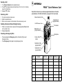
PR860
Portable Radio
User Guide
6881098C02-O
Contents
CONTENTS
Safety . . . . . . . . . . . . . . . . . . . . . . . . . . . . . 3
Product Safety and RF
Exposure Compliance . . . . . . . . . . . . . . . . . 3
Radio Overview . . . . . . . . . . . . . . . . . . . . . 4
Parts of the Radio . . . . . . . . . . . . . . . . . . . . 4
PR860 Model . . . . . . . . . . . . . . . . . . . . . 4
On/Off/Volume Knob . . . . . . . . . . . . . . . 5
Channel Selector Knob . . . . . . . . . . . . . 5
LED Indicator . . . . . . . . . . . . . . . . . . . . . 5
Programmable Buttons . . . . . . . . . . . . . 5
Push-to-Talk (PTT) Button . . . . . . . . . . . 7
Microphone . . . . . . . . . . . . . . . . . . . . . . 7
Audio Indicators for
Programmable Buttons . . . . . . . . . . . . . . . . 7
Getting Started . . . . . . . . . . . . . . . . . . . . . 8
Battery Information . . . . . . . . . . . . . . . . . . . 8
Charging the Battery . . . . . . . . . . . . . . . 8
Battery Charge Status . . . . . . . . . . . . . . 9
Attaching the Battery . . . . . . . . . . . . . . 10
Removing the Battery . . . . . . . . . . . . . 10
11
11
11
12
12
13
13
14
14
14
14
Radio Calls . . . . . . . . . . . . . . . . . . . . . . .
Receiving a Selective Call . . . . . . . . . . . .
Receiving a Call Alert™ Page . . . . . . . . .
Sounding an Emergency Siren. . . . . . . . .
Repeater or Talkaround Mode . . . . . . . . .
Setting Tight or Normal Squelch. . . . . . . .
Setting the Power Level . . . . . . . . . . . . . .
15
15
15
15
15
16
16
Scan . . . . . . . . . . . . . . . . . . . . . . . . . . . . .
Starting or Stopping Scan. . . . . . . . . . . . .
Scanning a Priority Channel . . . . . . . .
Talkback . . . . . . . . . . . . . . . . . . . . . . . . . .
Deleting a Nuisance Channel . . . . . . . . . .
Restoring a Channel Back
to the Scan List . . . . . . . . . . . . . . . . . .
17
17
17
17
18
CONTENTS
Computer Software Copyrights . . . . . . . . . . 2
Accessory Information . . . . . . . . . . . . . . .
Attaching the Antenna . . . . . . . . . . . . .
Removing the Antenna . . . . . . . . . . . .
Attaching the Belt Clip . . . . . . . . . . . . .
Removing the Belt Clip . . . . . . . . . . . .
Attaching the Side Connector Cover . .
Turning The Radio On or Off . . . . . . . . . .
Adjusting the Volume . . . . . . . . . . . . . . . .
Selecting a Radio Channel . . . . . . . . . . . .
Sending a Call . . . . . . . . . . . . . . . . . . . . .
Receiving a Call . . . . . . . . . . . . . . . . . . . .
18
1
English
Contents
CONTENTS
Scan Channel Discovery Alert . . . . . . . . . 18
Accessories . . . . . . . . . . . . . . . . . . . . . .
Carry Accessories. . . . . . . . . . . . . . . . . . .
Chargers . . . . . . . . . . . . . . . . . . . . . . . . . .
Headsets . . . . . . . . . . . . . . . . . . . . . . . . .
Surveillance . . . . . . . . . . . . . . . . . . . . . . .
Remote Speaker Microphones . . . . . . . . .
Adapters . . . . . . . . . . . . . . . . . . . . . . . . . .
Batteries . . . . . . . . . . . . . . . . . . . . . . . . . .
Antennas . . . . . . . . . . . . . . . . . . . . . . . . .
Miscellaneous . . . . . . . . . . . . . . . . . . . . . .
2
English
19
19
19
20
21
22
22
22
23
23
COMPUTER SOFTWARE
COPYRIGHTS
The Motorola products described in this manual
may include copyrighted Motorola computer
programs stored in semiconductor memories or
other media. Laws in the United States and
other countries preserve for Motorola certain
exclusive rights for copyrighted computer
programs, including, but not limited to, the
exclusive right to copy or reproduce in any form
the copyrighted computer program. Accordingly,
any copyrighted Motorola computer programs
contained in the Motorola products described in
this manual may not be copied, reproduced,
modified, reverse-engineered, or distributed in
any manner without the express written
permission of Motorola. Furthermore, the
purchase of Motorola products shall not be
deemed to grant either directly or by implication,
estoppel, or otherwise, any license under the
copyrights, patents or patent applications of
Motorola, except for the normal non-exclusive
license to use that arises by operation of law in
the sale of a product.
Safety
SAFETY
PRODUCT SAFETY AND RF
EXPOSURE COMPLIANCE
!
Caution
For a list of Motorola-approved antennas,
batteries, and other accessories, visit the
following web site which lists approved
accessories: http://www.motorola.com/cgiss/
index.shtml.
Before using this product, read the
operating instructions for safe usage
contained in the Product Safety and
RF Exposure booklet enclosed with
your radio.
ATTENTION!
SAFETY
This radio is restricted to occupational use
only to satisfy FCC RF energy exposure
requirements. Before using this product, read
the RF energy awareness information and
operating instructions in the Product Safety
and RF Exposure booklet enclosed with your
radio (Motorola Publication part number
68P81095C98) to ensure compliance with RF
energy exposure limits.
3
English
Radio Overview
RADIO OVERVIEW
PARTS OF THE RADIO
PR860 Model
RADIO OVERVIEW
Channel Selector Knob
Top Button (TB)
(programmable)
On/Off/Volume Knob
LED Indicator
Side Button 1 (A)
(programmable)
Push-to-Talk (PTT)
Button
Microphone
Side Button 2 (B)
(programmable)
Side Button 3 (C)
(programmable)
4
English
Side
Connector
Cover
Radio Overview
On/Off/Volume Knob
Turns the radio on or off, and adjusts the
radio’s volume.
Channel Selector Knob
Switches the radio to different channels.
Each button can access up to two features,
depending on the type of button press:
short press—quickly pressing and releasing the programmable buttons, or
•
long press—pressing and holding the programmable buttons for at least 1 1/2 seconds, or
•
hold down—pressing and holding down
the programmable buttons while checking
status or making adjustments.
LED Indicator
Indicates status of battery, power-up,
scanning, and receipt of a selective call.
Programmable Buttons
Several of your radio’s buttons can be
programmed by your dealer as shortcut
buttons for many of the radio’s features.
Check with your dealer for a complete list of
functions your radio supports.
Programmable buttons include:
•
The three Side Buttons (A, B, C) and the
Top Button (D)
The table on page 6 summarizes the
programmable features available and shows
the page number where the feature is
explained.
In the “Button” column, have your dealer write
down the programmable buttons next to the
features that have been programmed to them.
RADIO OVERVIEW
•
Use the abbreviations (e.g., A for Side
Button 1, D for Top Button, etc.) shown in the
radio illustration at the front of this manual.
Also, where a choice exists, have your dealer
indicate whether the button press is short
press (SP) or long press (LP).
5
English
Radio Overview
RADIO OVERVIEW
Function
Long Press
Hold Down
Cancel Emergency Siren.
—
15
—
—
Emergency
(Top button only)
Initiate Emergency
Siren.
Monitor
Turn monitor function Continually monitor
off.
selected channel.
Page Button
Volume Set
—
—
Sound a tone for
adjusting your
radio’s volume
level.
Battery Gauge
—
—
Check the battery’s
charge status.
9
—
18
Toggle scan on and
off.
Power level
Toggle transmit power level between High and
Low.†
—
16
Repeater/
Talkaround
Toggle between using a repeater or transmitting
directly to another radio.†
—
15
Squelch
Toggle squelch level between Tight and
Normal.†
—
16
Option Board
(if one is installed)
Toggle between activating and deactivating the
option board.†
—
—
Radio Call
Make a radio call.†
—
15
6
Delete a nuisance channel while scanning.
14
Scan/Nuisance
Channel Delete
†
English
Short Press
This function is activated by EITHER a short press OR a long press, but not both.
Radio Overview
Push-to-Talk (PTT) Button
Press and hold down this button to talk;
release it to listen.
AUDIO INDICATORS FOR
PROGRAMMABLE BUTTONS
High-Low Tone
Microphone
When sending a message, hold the
microphone 1 to 2 inches (2.5 to 5 cm) away
from your mouth, and speak clearly into the
microphone.
Low-High Tone
Some programmable buttons use tones to
indicate one of two modes:
High-Low Tone Low-High Tone
Scan
Start scan
Stop scan
Power Level
Low power
selected
High power
selected
Squelch
Tight squelch
Normal squelch
Option Board
Activated
Deactivated
Repeater/
Talkaround
Does not use
repeater
Uses repeater
RADIO OVERVIEW
Button
7
English
Getting Started
GETTING STARTED
BATTERY INFORMATION
Charging the Battery
If a battery is new, or its charge level is very
low, you will need to charge it before you can
use it.
GETTING STARTED
Note: Batteries are shipped uncharged from
the factory. Always charge a new battery 14 to 16 hours before initial use,
regardless of the status indicated by
the charger.
8
English
To charge the battery:
Place the battery, with or without the radio, in
the charger. The charger LED indicates the
charging progress:
LED color
Status
No LED
Indication
Battery inserted incorrectly.
Single Green
Flash
Successful charger power-up.
Flashing
Red*
Battery unchargeable or not making proper contact.
Steady Red
Battery in rapid-charge mode.
Flashing
Yellow
Battery in charger, not in rapid-charge
mode but waiting to be charged.
Getting Started
LED color
Status
Flashing
Green†
Battery 90% (or more) charged.
Steady
Green
Battery fully charged.
* Remove the battery from the charger and use a pencil
eraser to clean the four metal contacts on the bottom of
the battery. Place the battery back in the charger. If the
LED indicator continues to flash red, replace the battery.
† A standard battery may require one hour to charge to
90%.
Battery Charge Status
You can check battery charge status by
holding down the preprogrammed Battery
Gauge button (see page 6). The charge status
is shown by the color of the radio’s LED
indicator.
Battery Level
LED Indicator
High
Green
Sufficient
Yellow
Low
Blinking red
Very Low
None
Battery chargers only charge the Motorolaauthorized batteries listed at Chargers on
page 19; other batteries may not charge.
GETTING STARTED
9
English
Getting Started
Attaching the Battery
Removing the Battery
Battery
Latches
2
2
3
GETTING STARTED
1
1
Fit the extensions at the bottom of the battery
into the bottom slots on the radio.
2
Press the top part of the battery toward the
radio until you hear a click.
10
English
1
Turn off the radio (see page 13).
2
Slide both battery latches downward.
3
Pull the top part of the battery away from the
radio.
Getting Started
ACCESSORY INFORMATION
Attaching the Antenna
Turn the antenna counterclockwise to remove
it.
GETTING STARTED
Turn the antenna clockwise to attach it.
Removing the Antenna
11
English
Getting Started
Attaching the Belt Clip
Removing the Belt Clip
Belt Clip Tab
1
GETTING STARTED
2
1
Align the grooves of the belt clip with those of
the battery.
1
Use a key to press the belt clip tab away from
the battery.
2
Press the belt clip downward until you hear a
click.
2
Slide the belt clip upward to remove it.
12
English
Getting Started
Attaching the Side Connector Cover
TURNING THE RADIO ON OR OFF
Antenna
Loop
Slot
Thumbscrew
ON
1
Place the loop (attached to the side connector
cover) over the antenna; then slide it
downward until it touches the top of the radio.
Insert the tab on the top of the cover into the
slot above the connector.
3
Position the cover over the connector and
align the thumbscrew with the threaded hole
in the radio.
4
Tighten the thumbscrew to hold the cover in
place. Do not overtighten the thumbscrew.
If power-up is successful, you will hear
the Self-Test Pass
Tone
Turn the On/Off/
Volume Control knob
counterclockwise until
you hear a click.
GETTING STARTED
2
Turn the On/Off/
Volume Control knob
clockwise.
OFF
and see the LED turn
green.
If the radio fails to
power up, you will
hear the Self-Test Fail
Tone
.
13
English
Getting Started
ADJUSTING THE VOLUME
1
2
3
SENDING A CALL
Hold down the Volume Set or Monitor button (see page 6); you will hear a continuous
1
Turn your radio on.
tone.
2
Use the Channel Selector knob to select the
desired channel.
Turn the On/Off/Volume Control knob to the
desired volume level.
3
Hold the radio in a vertical
position, press the PTT button,
and talk at a distance of about
1 to 2 inches (2.5 to 5 cm)
from the microphone.
4
Release the PTT button to listen.
Release the Volume Set or Monitor button.
SELECTING A RADIO CHANNEL
Your radio offers either 4 or 16 channels.
GETTING STARTED
Note: Due to government regulations, some
channels may not be programmed. Ask
your dealer for more information.
To select a channel, turn the Channel
Selector knob clockwise or counterclockwise
until you reach the desired channel.
14
English
RECEIVING A CALL
1
Turn your radio on.
2
Adjust the radio’s volume (see page 14).
3
Switch to the desired channel.
4
If at any time a call comes through, you will
hear the call at the volume level you have set.
Radio Calls
RADIO CALLS
When you receive a selective call:
•
You will hear two alert tones.
•
The LED Indicator will light yellow.
To answer the call, press the PTT button.
RECEIVING A CALL ALERT™ PAGE
(16-channel models only)
When your radio receives a Call Alert page, it
sounds four alert tones continuously until you
respond.
Press the PTT button to answer the Call Alert
page, or press any other key to cancel it.
Note: Your radio will not receive any Selective
Calls until you clear the page.
When the orange Top button is pressed, your
radio will sound a loud, piercing Emergency
Siren (see page 6), if programmed by your
dealer (see page 5).
To stop the Emergency Siren, press the
Emergency button again.
RADIO CALLS
RECEIVING A SELECTIVE CALL
(16-channel models only)
SOUNDING AN EMERGENCY SIREN
REPEATER OR TALKAROUND
MODE
Talkaround Mode enables you to communicate
with another radio when either:
•
the repeater is not operating
–or–
•
your radio is out of the repeater’s range but
within communicating distance of another
radio.
Press the preprogrammed Repeater/
Talkaround button (see page 6) to toggle
between Repeater Mode and Talkaround
Mode.
15
English
RADIO CALLS
Radio Calls
SETTING TIGHT OR NORMAL
SQUELCH
Use this feature to filter out nuisance
(unwanted) calls and/or background noise.
However, tightening squelch could cause calls
from remote locations to be filtered out as well.
In this case, normal squelch may be more
desirable.
Press the preprogrammed Squelch button
(see page 6) to toggle between tight and
normal squelch.
SETTING THE POWER LEVEL
Each channel in your radio has a predefined
transmit power level that can be changed:
•
High power allows you to reach a radio that
is farther away.
•
Low power conserves the battery’s charge.
•
Auto power automatically sets the optimal
power level based on the strength of the
signal received. If the received signal is
weak, the transmit level will be set to high,
and vice-versa.
Note: Be aware that a message received
from a nearby radio might change
your radio’s power level to low. This
may cause radios that are farther
away not to receive your transmissions.
Press the preprogrammed Power Level button
(see page 6) to toggle between low and high
power.
16
English
Scan
SCAN
You can monitor multiple channels and receive
any calls that are transmitted on them.
Depending on your radio model, either four or
sixteen different channels can be programmed
into each scan list by the dealer. Your radio will
automatically switch to a scan list channel
when it detects activity on it.
Priority Channel
Scanning Sequence
None specified
Ch1➠Ch2➠Ch3➠
Ch4➠…Ch1
Channel 2
Ch2➠Ch1➠Ch2➠Ch3➠
Ch2➠Ch4➠Ch2➠…Ch1
STARTING OR STOPPING SCAN
TALKBACK
The LED indicator blinks green during a scan
operation, and stops blinking when the radio
switches to a channel.
While your radio is scanning, Talkback allows
you to participate in a call in progress. You must
press the PTT button to participate in the call;
otherwise, scanning continues to the next
channel.
To start or stop a scanning, press the
preprogrammed Scan button (see page 6).
SCAN
Note: The same channels can be assigned to
different scan lists.
Note: Even if there is activity on a non-priority
channel, your radio will automatically
switch to an active priority channel, and
indicate the activity with a short tone.
Scanning a Priority Channel
You may want to check the activity on one
channel more frequently than others. Your
dealer is able to prioritize channels for you. For
example:
17
English
SCAN
Scan
DELETING A NUISANCE CHANNEL
SCAN CHANNEL DISCOVERY ALERT
If a channel continually generates unwanted calls
or noise (a “nuisance” channel), use the Scan
button to temporarily delete the channel from the
scan list:
This feature enables you to identify the last
channel monitored before scanning was
stopped. To identify the last channel monitored, turn the Channel Selector knob until
you hear an alert tone.
1
While the radio is on the nuisance channel, hold
down the Scan button until you hear a tone.
2
Release the Scan button. The nuisance channel is deleted.
Note:You cannot delete a priority channel or the
last remaining channel in a scan list.
Restoring a Channel Back
to the Scan List
To restore a previously deleted channel back
to the scan list, restart the scan operation or
turn your radio off and on again.
18
English
Accessories
ACCESSORIES
Motorola offers a number of accessories to
enhance the productivity of your two-way
radio. Many of the available accessories are
listed below. For a complete list, see your
Motorola dealer.
CARRY ACCESSORIES
2 1/2” Spring Action Belt Clip
Portable Radio Hanger (for door panels
from 2.75” to 3.25”)
HLN9985
Waterproof Bag
NTN5243
Shoulder Strap
CHARGERS
WPLN4182
impresTM 120 Volt Single-Unit Charger
WPLN4187
impresTM 120 Volt Multi-Unit Charger
WPLN4192
impresTM 120 Volt Multi-Unit Charger
with Display
AAHTN3000
120 Volt Single-Unit Rapid Rate
Intelli-Charger
AAHTN3003
120 Volt 6 Unit Rapid Rate
Intelli-Charger
HLN9844
2” Spring Action Belt Clip
HLN9952
Carry Holder Belt Clip
HLN9652
Leather Case with Belt Loop, Li-Ion
HLN9665
Leather Case with Belt Loop, NiMH &
NiCd
NLN7967
Wall Mount Kit for Multi-Unit Charger
HLN9670
Leather Case with Swivel, Li-Ion
WPLN4124_R
Battery Optimizing System II (BOS II)
HLN9676
Leather Case with Swivel, NiMH & NiCd
RL-76345
HLN9701
Nylon Case with Belt Loop
Battery Optimizing System (BOS II)
Adapter Plate
NTN8039
2.5" High Activity Swivel Belt Loop
RLN5233
Hard Wire Vehicular Charger
NTN8040
3" High Activity Swivel Belt Loop
RLN4883
Travel Charger
HLN6602
Universal Chest Pack
NDN4005
Battery Maintenance System Plus
(BMSPLUS), Three Station
RLN4815
RadioPAk Radio/Utility Case
WPLN4079_R
TDN9327
Portable Radio Hanger (for door panels
up to 2.75”)
Battery Maintenance System Plus
(BMSPLUS), Six Station
ACCESSORIES
HLN9714
TDN9373
19
English
Accessories
ACCESSORIES
WPLN4107_R
Motorola Conditioning Charger (MCC)
Singe-Unit with Adapter Plate
Ultra-Light Headset, Behind the Head
AARMN4017
Ultra-Light Headset, Earbud Style
Receiver
WPPN4065_R
Motorola Conditioning Charger (MCC)
Four Station
RMN4048
Temple Transducer
WPPN4082_R
Adapter Plate Only (use with MCC)
RMN5048
Rugged Temple Transducer
RLN4814
Vehicular Mounting Bracket For Single
Unit MCC
ENMN4016
Medium Duty Headset, Behind the
Head
WPPN4079_R
BMS Battery Adapter (for use with
NiCd & NiMH batteries)
AARMN4019
WPPN4080_R
BMS Battery Adapter (for use with
NiCd, NiMH & Li-Ion Batteries)
Medium Weight Over-the-Head
Headset with Noise Cancelling Mic &
Inline PTT
AARMN4032
Medium Weight Over-the-Head
Headset with Noise Cancelling Mic
RMN5047
NFL Style Heavy Duty Headset
(requires AAHLN9716 Adapter)
RMN5015
Racing Headset (RKN4091 adapter
cable required)
VEHICULAR ADAPTERS AND
ACCESSORIES
AAEN1006
Vehicular Adapter - VHF
AAEN1007
Vehicular Adapter - UHF
AARMN4020
ENKN4002
Programming Cable for VHF and UHF
Vehicular Adapters
Push-to-Talk or VOX Heavy Duty
Headset
RMN4051
GKN6270
Power Cable with 10A Fuse
2-Way Hard-Hat Mount Headset, Black
(requires RKN4097 adapter cable)
GSN6059
13 W External Speaker
RMN4052
Tactical Headband Style Headset, Gray
(requires RKN4097 adapter cable)
RMN4053
Tactical Hard-Hat Mount Headset, Gray
(requires RKN4097 adapter cable)
RMN4054
Receive Only Hard-Hat Mount Headset
RMN4055
Receive Only Headband Style Headset
HEADSETS
AARMN4018
Lightweight Single Muff Headset
with Swivel Boom Mic & Inline PTT
AARMN4031
Lightweight Single Muff Adjustable
Headset with Swivel Boom Mic
20
English
ENMN4012
Accessories
ADAPTERS AND CABLES
AAHLN9716
Adapter for Audio Accessories
RKN4097
In-Line PTT Adapter Cable
RKN4091
Adapter Cable (for use with RMN5015)
SURVEILLANCE
AARMN4021
Receive Only Earpiece, 1-wire, Beige
CommPort
Integrated Ear Microphone/Receiver
System with PTT on Radio Adapter
NTN1723
Integrated Ear Microphone/Receiver
System with Palm PTT
NTN1724
Integrated Ear Microphone/Receiver
System with Ring PTT
NTN1737
Integrated Ear Microphone/Receiver
System with Snap-on-Side PTT
NNTN4187
Integrated Ear Microphone/Receiver
System with Body PTT
AARMN4028
Receive Only Earpiece, 1-wire, Black
AARMN4022
Earpiece with Microphone and Push-toTalk Combined, 2-Wire, Beige
AARMN4029
Earpiece with Microphone and Push-toTalk Combined, 2-Wire, Black
ENMN4017
Earpiece with Microphone and Push-toTalk Combined, 3-Wire, Beige
BDN6677
Ear Microphone for Standard Noise
Levels, Black
ENMN4014
Earpiece with Microphone and Push-toTalk Combined, 3-Wire, Black
BDN6678
Ear Microphone for Standard Noise
Levels, Beige
NTN8370
Extreme Noise Kit
BDN6641
NTN8371
Low Noise Kit
Ear Microphone for High Noise Levels,
Gray
RLN5316
Comfort Earpiece with Microphone and
PTT Combined, 2-Wire, Beige
RLN5315
Comfort Earpiece with Microphone and
PTT Combined, 2-Wire, Black
RLN4922
Completely Discreet Earpiece Kit
ENMN4013
Flexible Ear Receiver
EAR MICROPHONE SYSTEM
AARMN404
4 Push-to-Talk Only Interface Module
AARMN404
5 Push-to-Talk or Voice Activated Interface Module
0180358B38
Push-to-Talk Ring Switch
0180300E83
Push-to-Talk Body Switch
0180300E25
Earguard with Adjustable Loop
ACCESSORIES
NTN1722
21
English
Accessories
ACCESSORIES
MICROPHONES
AAHMN9052
Remote Speaker Microphone
NAD6502_R
VHF 146-174 MHz, Heliflex
AAHMN9053
Noise-Cancelling Remote Speaker
Microphone
PMAD4012
VHF 136-155 MHz 9 cm, Stubby
PMAD4025
VHF 150-161 MHz, Stubby
AAHMN9054
UHF Public Safety Speaker
Microphone
AAHMN9057
VHF Public Safety Speaker
Microphone
RMN5055
Heavy Duty Remote Speaker
Microphone
BATTERIES
HNN4001
impresTM NiMH, 1900 mAH, 7.5 V
HNN4002
impresTM NiMH, 1800 mAH, 7.5 V,
Intrinsically Safe
HNN4003
impresTM Li-Ion, 2000 mAH, 7.5 V
HNN9008_R
Premium NiMH, 1500 mAH, 7.5 V (not
compatible with low band models)
HNN9009_R
Premium NiMH, 1900 mAH, 7.5 V
HNN9010_R
Premium NiMH, 1800 mAH, 7.5 V,
Intrinsically Safe
HNN9011_R
Premium NiCd, 1200 mAH, 7.5 V,
Intrinsically Safe
HNN9012_R
Premium NiCd, 1300 mAH, 7.5 V
HNN9013_R
Premium Li-lon, 1200 mAH, 7.5 V
22
English
ANTENNAS
PMAD4013
VHF 155-174 MHz 9 cm, Stubby
8504762J01
VHF 136-155 MHz 14 cm, Whip
NAD6579
VHF 148-161 MHz, Whip
PMAD4023
VHF 150-161 MHz, Whip
8504762J02
VHF 155-174 MHz 14 cm, Whip
PMAE4002
UHF 403-433 MHz, Stubby
8504762J08
UHF 433-470 MHz, Stubby
NAE6483_R
UHF 403-520 MHz, Whip
NAB6064
Low Band 30-50 MHz, Heliflex
Sending a Call
1. Turn Channel Selector knob to desired channel.
2. Press PTT and speak clearly with mouth about 2.5 to 5 cm (1 to 2 inches)
away from microphone.
3. Release PTT to listen.
Receiving a Call
1. Turn radio on and set volume level.
2. Switch to desired channel.
3. When a call is received, it will be heard at the volume level you set.
PR860™ Quick Reference Card
Record the functions for your radio’s programmable buttons in the table
provided below. For further information, see page 6 in this User Guide.
Channel Selector Knob
Top Button (D)
(programmable)
On/Off/Volume Knob
Deleting a Nuisance Channel During Scanning
1. While on a nuisance channel, press and hold preprogrammed Scan button
until you hear a tone.
2. Release Scan button.
LED Indicator
Side Button 1 (A)
(programmable)
Sounding an Emergency Siren
•
•
Microphone
Press preprogrammed Emergency button (Top button [D]) to sound
Emergency Siren.
Press Emergency button again to stop Emergency Siren.
Push-to-Talk (PTT)
Button
Side Button 2 (B)
(programmable)
Side Button 3 (C)
(programmable)
Button
Function
Short Press
Long Press
Hold Down
Page
Motorola, Inc.
8000 West Sunrise Boulevard
Ft. Lauderdale, FL 33322
MOTOROLA, and the Stylized M Logo are registered in
the U.S. Patent and Trademark Office. All other product or
service names are the property of their respective owners.
© Motorola, Inc. 2004.
All rights reserved.
*6881098C02*
6881098C02-O