1
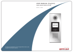
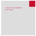
Meridian C Series
Installation Components
C51
5ch x 2 (bass/treble)
Active Speaker Power Unit
Installation and Operation Manual
IMPORTANT: PLEASE READ THIS COMPLETE MANUAL TO ENSURE PROPER
INSTALLATION AND OPERATION.
INSTALLERS:
Please review this manual carefully before contacting Technical Support.
PRODUCT OWNERS: Please contact your authorised Meridian dealer for product or installation
questions.
This page intentionally left blank
Contents
IMPORTANT SAFETY INSTRUCTIONS...............................................................................................4
SERVICE AND GUARANTEE.............................................................................................................5
ABOUT THE PRODUCT....................................................................................................................6
C51 SPECIFICATIONS......................................................................................................................6
INSTALLATION AND SETUP..............................................................................................................7
CONNECTING THE C51...................................................................................................................8
OPERATING THE C51......................................................................................................................9
TROUBLESHOOTING.......................................................................................................................9
Please review the instructions in the following pages of this manual to help insure a smooth
installation and a happy customer.
Copyright © 2007 Meridian Audio Limited. No part of this document may be copied, photocopied, translated, or
reproduced to any electronic medium or machine readable form without prior consent, in writing, from Meridian.
Specifications subject to change without notice. All Rights Reserved.
3
IMPORTANT
SAFETY INSTRUCTIONS
Safety warnings
• Do not expose the unit to dripping or splashing.
• Do not place any object filled with liquid, such
as a vase, on the unit.
• Do not place naked flame sources, such as
lighted candles, on the unit.
•
•
•
•
•
•
Read the instructions.
Keep these instructions.
Follow all instructions.
Do not use this apparatus near water.
Clean only with a dry cloth.
Install only in accordance with manufacturer’s
instructions.
• Refer all servicing to approved service personnel.
To avoid interference
Do not position the unit:
• Near strong magnetic radiation.
• Near to a television, or where connecting cables
may be subject to or cause interference.
This apparatus has been designed with Class
1 construction and must be connected to a
mains socket outlet with a protective earth
connection (the third grounding prong).
To avoid overheating
• Leave at least 10cm around the equipment to
ensure sufficient ventilation.
Do not position the product:
• In direct sunlight.
• Near heat sources, such as a radiator.
• Stacked with any other audio products other
than in a properly ventilated rack, as the heat it
generates may damage the other products.
Do not defeat the safety purpose of the
polarized or grounding-type plug. A polarized
plug has one prong wider than the other. A
grounding type plug has two blades and a
third grounding prong. The wide blade or the
third prong are provided for your safety. If the
provided plug does not fit into your outlet,
consult an electrician for replacement of the
obsolete outlet.
The sides and top of the C51 case contain
venting holes for the internal heatsinks which
should not be obstructed. Ensure that air can
flow around them. The product normally runs
warm to the touch when not in standby.
WARNING: TO REDUCE THE RISK OF FIRE
OR ELECTRIC SHOCK, DO NOT EXPOSE THIS
APPARATUS TO RAIN OR MOISTURE
Warning: The C51 is moderately heavy; take
care when lifting it.
This apparatus uses a single-pole power
switch. As a result it is not isolated from AC
mains power when switched off at the rear
panel. The apparatus may be isolated from
mains power either by unplugging the power
connector from the rear of the unit, or by
unplugging the connector at the opposing
end of the power cord or cable from its supply
outlet. As a result, either or both of these
connectors should remain accessible.
Radio interference
FCC Warning: This equipment generates
and can radiate radio frequency energy
and if not installed and used correctly in
accordance with our instructions may cause
interference to radio communications or radio
and television reception. It has been typetested and complies with the limits set out in
Subpart J, Part 15 of FCC rules for a Class B
computing device. These limits are intended
to provide reasonable protection against such
interference in home installations.
EU: This product has been
designed and type-tested to
comply with the limits set out in
EN55013 and EN55020.
4
Warning: live terminals
Terminals marked with the ‘lightning
flash’ symbol are hazardous live and the
external wiring connected to these
terminals requires installation by an
instructed person or the use of readymade leads or cords.
Accessory Kit
The following items are supplied with C51
Powered Crossover/Amplifier unit
1 - This manual
1 - Power Cord
Information for Users on Disposal of
Old Equipment (EU Only)
Service
Service and guarantee
The Meridian components have been carefully
designed to give years of untroubled service.
There are no user-serviceable parts inside the
case, nor do the units require any form of
maintenance.
Attention:
This symbol is only
valid in the European
Union.
[European Union]
This symbol indicates that the electrical and
electronic equipment should not be disposed
as general household waste at its end-oflife. Instead, the product should be handed
over to the applicable collection point for the
recycling of electrical and electronic equipment
for proper treatment, recovery and recycling
in accordance with your national legislation.
By disposing of this product correctly, you will
help to conserve natural resources and will
help prevent potential negative effects on the
environment and human health which could
otherwise be caused by inappropriate waste
handling of this product. For more information
about collection point and recycling of this
product, please contact your local authority,
your household waste disposal service or
the shop where you purchased the product.
Penalties may be applicable for incorrect
disposal of this waste, in accordance with
national legislation.
In the unlikely event that your subwoofer fails
to function correctly, it should be returned, in
its original packaging, to your Meridian dealer.
In case of difficulty within the UK or USA
please contact Meridian Audio Limited or
Meridian America Inc respectively.
In case of difficulty outside the UK or USA,
contact the importing agent for the territory. A
list of Meridian agents abroad is available from
Meridian.
No responsibility can be accepted for the
subwoofer whilst in transit to the factory or an
agent, and customers are therefore advised to
insure the unit. When seeking service under
guarantee, proof of the date of purchase will
be required.
Guarantee
Each unit is guaranteed against defects in
material and workmanship for two years from
the date of purchase.
(Business users)
If you wish to dispose of this product, contact
your Meridian dealer or distributor or Meridian
Audio Ltd to obtain information about the
take-back of the product.
The guarantee is void if the unit has been
subject to misuse, accident, or negligence,
or has been tampered with or modified in
any way without the written authorisation of
Meridian Audio Limited.
[Other Countries outside the European
Union]
If you wish to dispose of this product, please
do so in accordance with applicable national
legislation or other rules in your country for
the treatment of old electrical and electronic
equipment.
5
Note: Connecting anything other than the
correct network lead to the COMMS sockets
may cause damage to the unit which will not
be covered by this guarantee.
Attempted servicing by unauthorised people
may also invalidate this guarantee. Labour and
carriage charges are not covered unless by
local agreement.
Front-panel indicators take the form of blue
LEDs for main power and for each channel,
arranged in high/low pairs so that the status
can be instantly assessed.
Outside the UK, local warranty liability is
restricted to equipment purchased within
the territory. Our agents abroad are only
under contractual obligation to service under
guarantee equipment sold through them. They
are entitled to make a non-refundable charge
for any service carried out on other equipment.
This guarantee does not limit your statutory
rights within the United Kingdom.
The rear panel is divided into five channel
pairs identified as HF (tweeter) and LF (bass).
A single full-range input per channel pair
may be switch-selected between unbalanced
(gold-plated phono connector) and balanced
(XLR3F).
In addition to the power input socket and
power switch, the rear panel also offers a
3.5mm jack socket for connection of an
industry standard trigger input (5–30V, AC or
DC) for remote operation, and a 3.5mm jack
socket for the connection of a 12V DC fan
system. This output is controlled automatically
according to temperature.
ABOUT THE PRODUCT
The C51 powers 200 and 300 Series Remote
Active installation loudspeakers.
It features active line-level crossovers, switched
balanced and unbalanced inputs, and employs
a powerful new amplifier design which enables
multiple channels of high-level amplification
to be combined in a compact unit without
excessive heat.
C51 Powered Crossover/Amplifier
Output power
Ten channels of approximately100W into
8Ω (160W into 4Ω) RMS amplification are
provided, grouped into five pairs, each
providing bass and tweeter outputs from a
full-range input.
10 channels of 100W into 8Ω
/ 160W into 4Ω, arranged in
5 x HF/LF pairs sourced from
full-range input via crossover
module
Frequency response +0/–3dB, 10Hz–50 kHz
(modified by crossover
characteristics)
Output impedance 20–150mΩ, 1–20kHz
The crossovers take the form of plug-in
modules which can be inserted at the time
of installation to configure the unit for the
speakers in use. An appropriate card is
supplied with each loudspeaker. Modules are
currently available for the A320, A330 and
A350, and each module includes a pair of
LEDs that confirm the positive and negative
power-rails are operative and identifies the
crossover installed by means of the colour
combination.
THD+Noise
Typical: 0.1% @ 60W output,
0.008% @ 1W
Full-range Inputs
5 x Mono unbalanced (phono)
impedance 10 kΩ
5 x Mono balanced (XLR3F)
impedance 20 kΩ/leg
Switch-selected between
balanced and unbalanced
Outputs
LF and HF pairs of gold-plated
binding posts per channel pair
Other connections 12vdc, 5W Temperature
controlled fan output (3.5mm
jack)
5–30V ac/dc trigger input
(3.5mm jack)
Thermal, short-circuit and DC fault protection
circuitry is included. The C51 has soft start, fan
output and trigger input.
The front panel includes five sockets for
installation of the crossover cards, which can
be accessed by unscrewing the transparent
smoked access cover.
Controls 6
Rear-panel balanced/
unbalanced input switch per
input.
Rear panel main power
switch.
Indicators
Power
Dimensions
Main enclosure
Front panel
Weight
INSTALLATION AND SETUP
Blue LED power indicator
Per-channel blue LED
operation indicator
Unpacking
• Inspect product box and unit for any shipping
damage.
• Save product box in the event the unit needs to
be shipped in the future. Shipping the unit in a
generic box may void warranty.
100–240Vac, 30–1200VA
435 x 82 x 250 mm (17.25 x
3.25 x 9.75 in) W x H x D
485 x 87.5 x 12 mm (19 x
3.45 x 0.5 in) W x H x D
Mounting
The C51 is primarily designed to be mounted
in a standard 19in rack. Feet are provided for
free-standing operation: these should not be
present if the unit is to be rack-mounted.
TBC kg (xx lb)
Crossover cards
Cards are supplied with each active installation
loudspeaker system. These feature premium
quality Burr-Brown operational amplifiers and
four-layer printed circuit boards. LEDs indicate
presence of rail voltages while the colour
combinations confirm the type of crossover
in place. Cards plug into sockets on the front
panel of the C51.
• EXCESSIVE HEAT MAY CAUSE THE UNIT TO
MALFUNCTION OR SHORTEN PRODUCT LIFE.
Follow regular installation rules for proper
ventilation.
• Be sure rack location has adequate ventilation.
Allow a minimum of 1U rack space (1.75in)
above and below unit for ventilation.
• Allow additional ventilation when mounted
near other power amplifiers or other equipment
that may generate excessive heat.
Meridian Audio reserves the right to amend
product specifications at any time.
Connections
Be sure to use high quality cables for both
sources and output signals.
AC Power Connector
Connect to a stable AC power line. Ensure
that the unit is connected to a supply of the
voltage specified on the unit and that the unit
is of the correct type for the territory in which
it is being installed.
• To avoid ground loops, a power conditioner for
the equipment rack is recommended.
• Static electricity can cause equipment problems.
Be sure installer is grounded to chassis or
equipment rack before connecting sources.
7
Stand By
Hot
5 - 30V ac or dc
OFF
ON
POWER INPUT ~50-60Hz 30-1200VA MAX
FAN OUTPUT
UNBALANCED
INPUT
BALANCED
BASS
BALANCED
BASS
CHANNEL 1
MERIDIAN
CONTROLLED
TWEETER
OUTPUT
UNBALANCED
CHANNEL 2
INPUT
OUTPUT
UNBALANCED
INPUT
BASS
TWEETER
BALANCED
UNBALANCED
INPUT
BASS
CHANNEL 3
TWEETER
OUTPUT
BASS
CHANNEL 4
BALANCED
INPUT
TWEETER
BALANCED
OUTPUT
UNBALANCED
CHANNEL 5
OUTPUT
TWEETER
TRIGGER INPUT
Connecting the C51
CAUTION REPLACE WITH SAME TYPE FUSE
T10AH for 100-120V ac ~
C51 Rear Panel (above) and front panel with acrylic cover in place (below)
C51 Active Speaker Power Unit
Bass
Treble
Channel 1
Channel 2
Channel 3
Channel 1
Crossover
Channel 4
Channel 2
Crossover
Channel 3
Crossover
Channel 4
Crossover
Channel 5
Crossover
Channel 5
Hot
TRIGGER INPUT
OFF
ON
POWER INPUT ~50-60Hz 30-1200VA MAX
BASS
FAN OUTPUT
5 - 30V ac or dc
UNBALANCED
INPUT
CHANNEL 1
MERIDIAN
CONTROLLED
UNBALANCED
INPUT
BASS
TWEETER
BALANCED
Two full-inputs are provided for each channel:
balanced (XLR-3F) and unbalanced (goldplated phono). The active input is selected
with a slide switch.
CHANNEL 2
OUTPUT
BASS
TWEETER
BALANCED
UNBALANCED
CHANNEL 3
Note that these terminals can develop
significant voltages/current-passing capability
when the C51 is powered up and being
fed with an active signal. Ensure that
connections are made with the power
disconnected from the unit.
OUTPUT
BASS
TWEETER
OUTPUT
UNBALANCED
OUTPUT
BALANCED
OUTPUT
Input connections
BASS
CHANNEL 4
INPUT
TWEETER
BALANCED
UNBALANCED
CHANNEL 5
INPUT
TWEETER
INPUT
The C51 contains five identical channel pairs
(bass/treble) of audio amplification. Unless
otherwise stated, this section refers to one
channel only.
BALANCED
Stand By
You can connect five Meridian Active
Installation Loudspeakers (such as the A320,
A330, A350, or A200Z) to the C51. The C51
is designed specifically for use with Meridian
Active Installation Loudspeakers, each of which
is supplied with the appropriate crossover
module. As a result the unit cannot be used
with other loudspeakers.
CAUTION REPLACE WITH SAME TYPE FUSE
T10AH for 100-120V ac ~
The audio connections should be made with
high quality audio phono leads or XLR leads.
Trigger input
• Connect each Meridian Active Installation
Loudspeaker to the appropriate outputs, using
two pairs of speaker cables for each speaker
connected to the BASS + and -, and the
TWEETER + and - terminals.
The unit is designed to be switched in and
out of standby by means of the application of
a trigger voltage via this 3.5 mm mono jack
socket. The application of an AC or DC voltage
between 5 and 30 volts will turn the unit on
(ie bring it out of standby). Removing the
voltage will return the unit to standby. Ensure
that the trigger source is configured to provide
a voltage within this range when the unit is
required to be switched on.
• Plug the crossover module supplied with
each Active Installation Loudspeaker into the
appropriate crossover bay on the front panel
of the C51, and re-fit the acrylic cover. Ensure
that the card is correctlly seated and that the
correct card for the speaker is in the appropriate
slot. Each crossover card includes indicator
lights that show the presence of power and, by
their colour combination, indicate the type of
speaker for which the card is designed.
Output connections
Connect the cables from the rear-panel output
terminals to the speaker units. Be sure to
observe correct polarity and the source and
destination of each channel.
• Connect the input for each channel to the
appropriate CHANNEL 1 to 5 INPUT, using either
the BALANCED or UNBALANCED input, and
setting each INPUT switch accordingly.
8
Meridian fan output
A further blue LED is situated next to the
Standby button and illuminates when the
unit is in standby, indicating that the unit is
powered. When this light is illuminated, the
channel indicators should be extinguished.
This 3.5mm jack provides a voltage and power
suitable for driving a Meridian fan system. The
voltage provided is 12vdc, tip positive. Up to
5W can be taken from this socket. The voltage
is present only when the temperature of the
unit exceeds 55 degrees Celsius measured at
the case of the unit.
A blue LED indicates when the unit has been
shut down as a result of overheating. In an
overtemperature situation the entire unit will
enter standby, irrespective of the status of
the trigger input and whether one or several
channels are the direct cause of overheating.
OPERATING THE C51
Removal of the smoked acrylic front panel
allows access to the Standby button and for
the insertion and/or removal of crossover
cards. Replace the panel after use to avoid
unintentional operation.
In this condition, normal operation will
continue as soon as the temperature returns
to safe levels, you are advised to be aware of
what may have caused the overheating issue.
Troubleshooting
Be sure to insert the correct card in the correct
slot.
Unit goes silent when played hard
The unit is normally operated via trigger input.
The unit has a temperature sensing system
on board, which prevents overheating of the
electronics. If the unit shuts down because of
overheating, the front-panel “hot” LED will
illuminate.
A front panel standby button is provided to
toggle the unit in and out of standby. It is not
intended that this button should be used for
normal operation.
Sound will continue when the unit has cooled.
However, you are strongly advised to be aware
of what may have caused the overheating
issue before continuing. Is the rack properly
ventilated and cooled? Does the associated fan
come on when the unit becomes hot (if using
the fan output on the unit)? Is sound coming
out of all the speakers?
Note that when mains power is applied to the
unit it will initially enter ACTIVE mode.
When the C51 is in standby mode, power rails
are turned off for a significant saving in energy
usage and thus reduced carbon emissions.
It is neither required nor recommended
to leave the amplifiers in active mode (ie
powered up) when not in use.
It is possible that the unit will shut down if
driven for abnormally long periods at unusually
high levels. If this is the case, simply wait
until the unit has cooled down and normal
operation will resume automatically.
When the unit is brought into active mode,
a ‘soft start’ timing circuit brings the main
toroidal power transformers online gently to
minimise current surges and unwanted startup
sounds.
There is radio interference
Indicators
Five pairs (bass/treble) of blue LEDs on
the front panel illuminate when the unit
is operating and confirm the presence of
power on all channels. All ten LEDs should
be illuminated during normal operation: if
a channel light is not illuminated, a fault
condition is indicated.
The unit has been designed to very high
standards of electromagnetic compatibility.
If this equipment does cause or suffer from
interference to/from radio or television
reception then the following measures should
be tried:
9
• Reorient the receiving aerial (or antenna) or
route the antenna cable of the receiver as far as
possible from the unit and its cabling.
• Ensure that the receiver uses well-screened
antenna cable.
• Relocate the receiver with respect to the unit.
• Connect the receiver and this product to
different AC outlets.
• If the problem persists contact your dealer.
type of crossover card in each bay matches
the type of loudspeaker connected to the
corresponding output channel. Each crossover
card includes indicator lights that show
the presence of power and, by their colour
combination, indicate the type of speaker for
which the card is designed. Confirm that these
are indicating correctly.
Drive units move when the C51 is
switched on or off
Unit stays in standby
This is normal as the amplifier electronics
settle.
The sound from one or more speakers
is either muffled (lacking in HF) or
thin (lacking in bass)
Check that the crossover cards have been
correctly inserted, and in particular that the
Meridian Audio Limited
Latham Road,
Huntingdon, Cambridgeshire PE29 6YE
United Kingdom
Tel +44 (0) 1480 445678
Fax +44 (0) 1480 445686
Web: www.meridian-audio.com
This generally indicates a problem with the
trigger connection and/or setup:
• Check the trigger cabling and that it is correctly
wired.
• Ensure that the source device providing the
trigger is configured to provide a voltage in the
range 5–30v ac or dc when the unit is required
to come out of standby and for the trigger
voltage to be removed when the unit is to enter
standby.
Meridian is registered trademark of Meridian Audio Ltd
Other trademarks are the property of their respective owners.
Meridian America Inc
8055 Troon Circle, Suite C
Austell, Atlanta GA 30168-7849
USA
Tel +1 (404) 344 7111
Fax +1 (404) 346 7111
Email: [email protected]
C51man v1.0 • REƒ • 20070727