1
SGI® NAS ISS3124-RP2 Server and
IS2224 JBOD Setup Guide
007-5922-001
COPYRIGHT
© 2013 SGI. All rights reserved; provided portions may be copyright in third parties, as indicated elsewhere herein. No permission is granted to copy, distribute,
or create derivative works from the contents of this electronic documentation in any manner, in whole or in part, without the prior written permission of SGI.
LIMITED RIGHTS LEGEND
The software described in this document is “commercial computer software” provided with restricted rights (except as to included open/free source) as specified
in the FAR 52.227-19 and/or the DFAR 227.7202, or successive sections. Use beyond license provisions is a violation of worldwide intellectual property laws,
treaties and conventions. This document is provided with limited rights as defined in 52.227-14.
The electronic (software) version of this document was developed at private expense; if acquired under an agreement with the USA government or any
contractor thereto, it is acquired as “commercial computer software” subject to the provisions of its applicable license agreement, as specified in (a) 48 CFR
12.212 of the FAR; or, if acquired for Department of Defense units, (b) 48 CFR 227-7202 of the DoD FAR Supplement; or sections succeeding thereto.
Contractor/manufacturer is SGI, 46600 Landing Parkway, Fremont, CA 94538.
TRADEMARKS AND ATTRIBUTIONS
SGI, and the SGI logo are registered trademarks and Rackable and Supportfolio are trademarks of, Silicon Graphics International in the United States and/or
other countries worldwide.
Fusion-MPT, Integrated RAID, MegaRAID, and LSI Logic are trademarks or registered trademarks of LSI Logic Corporation.
Intel, Itanium, and Xeon are trademarks or registered trademarks of Intel Corporation or its subsidiaries in the United States and other countries.
Internet Explorer and MS-DOS are registered trademarks of Microsoft Corporation.
OpenSolaris is a trademark of Sun Microsystems, Inc.
Linux is a registered trademark of Linus Torvalds, used with permission by SGI.
Novell and Novell Netware are registered trademarks of Novell Inc.
PCIe and PCI-X are registered trademarks of PCI SIG.
Phoenix and PhoenixBIOS are registered trademarks of Phoenix Technologies Ltd.
Red Hat and all Red Hat-based trademarks are trademarks or registered trademarks of Red Hat, Inc. in the United States and other countries.
SUSE LINUX and the SUSE logo are registered trademarks of Novell, Inc.
UNIX is a registered trademark in the United States and other countries, licensed exclusively through X/Open Company, Ltd.
All other trademarks mentioned herein are the property of their respective owners.
Adaptec, HostRAID, and the Adaptec logo are registered trademarks of Adaptec Inc.
Record of Revision
007-5922-001
Version
Description
001
October, 2013
First release
iii
Contents
1
Related Publications .
.
.
.
.
.
.
.
.
.
.
.
.
.
.
.
.
.
.
.
.
.
. xii
Introduction
.
.
.
.
.
.
.
.
.
.
.
.
.
.
.
.
.
.
1
.
.
.
.
.
.
System Overview
.
.
.
.
.
.
.
.
.
.
.
.
.
.
.
.
.
.
.
.
.
.
.
2
Optional IS2224 JBOD Storage
.
.
.
.
.
.
.
.
.
.
.
.
.
.
.
.
.
.
4
IS2224 JBOD Front-Panel Features
.
.
.
.
.
.
.
.
.
.
.
.
.
.
.
.
4
Next Steps .
2
.
.
.
.
.
.
.
.
.
.
.
.
.
.
.
.
.
.
.
.
.
.
.
6
Un-Racked NAS System Setup
.
.
.
.
.
.
.
.
.
.
.
.
.
.
.
.
.
7
Pre-Racked NAS System Setup
.
.
.
.
.
.
.
.
.
.
.
.
.
.
.
.
.
7
ISS3124-RP2 Server and IS2224 JBOD
NAS System Hardware Installation9
Unpack the System Enclosures .
.
.
.
.
.
.
.
.
.
.
.
.
.
.
.
.
.
.
.
9
Inspecting a Shipment .
.
.
.
.
.
.
.
.
.
.
.
.
.
.
.
.
.
.
.
.
9
Prepare for Setup
.
.
.
.
.
.
.
.
.
.
.
.
.
.
.
.
.
.
.
.
. 10
Choose a Setup Location
.
.
.
.
.
.
.
.
.
.
.
.
.
.
.
.
.
.
.
.
. 10
Warnings and Precautions .
.
.
.
.
.
.
.
.
.
.
.
.
.
.
.
.
.
.
.
. 10
General Enclosure Precautions .
.
.
.
.
.
.
.
.
.
.
.
.
.
.
.
.
.
. 11
Rack Mounting Considerations .
.
.
.
.
.
.
.
.
.
.
.
.
.
.
.
.
.
. 12
Ambient Operating Temperature .
.
.
.
.
.
.
.
.
.
.
.
.
.
.
.
.
.
. 12
Reduced Airflow
.
.
.
.
.
.
.
.
.
.
.
.
.
.
.
.
.
.
.
.
.
. 12
Mechanical Loading
.
.
.
.
.
.
.
.
.
.
.
.
.
.
.
.
.
.
.
.
. 12
Circuit Overloading.
.
.
.
.
.
.
.
.
.
.
.
.
.
.
.
.
.
.
.
.
. 12
Reliable Ground
.
.
.
.
.
.
.
.
.
.
.
.
.
.
.
.
.
.
.
.
. 13
Installing the ISS3124-RP2 NAS Server into a Rack .
.
.
.
.
.
.
.
.
.
.
.
.
. 13
Rackmounting an Optional IS2224 JBOD Enclosure .
.
.
.
.
.
.
.
.
.
.
.
.
. 17
.
.
.
.
.
.
.
.
.
.
.
.
. 18
Installing the IS2224 Storage Enclosure on the Rails .
.
.
.
.
.
.
.
.
.
.
.
. 19
.
Position the IS2224 Mounting Rails
007-5922-001
.
.
.
.
v
Contents
3
IS2224 JBOD Enclosure Cable Guide and Chassis Location .
.
.
.
.
.
.
.
.
.
. 23
Check all Cable Connections and Airflow .
.
.
.
.
.
.
.
.
.
.
.
. 27
.
.
.
.
.
.
.
.
.
.
.
.
.
.
.
.
.
.
. 27
Supply Power to the System .
.
.
.
.
.
.
.
.
.
.
.
.
.
.
.
.
.
.
.
. 27
ISS3124-RP2 NAS Operation and GUI Startup .
Overview .
.
.
.
.
.
.
.
.
.
.
.
.
.
. 29
.
.
.
.
.
.
.
.
.
.
.
.
.
.
.
.
.
.
. 29
Front Bezel and Control Panels .
.
.
.
.
.
.
.
.
.
.
.
.
.
.
.
.
.
. 29
.
.
.
.
.
.
.
.
.
.
.
.
.
.
.
.
.
. 32
Obtain a Permanent Software License Key .
.
.
.
.
.
.
.
.
.
.
.
.
.
.
.
.
.
.
.
.
.
. 32
Registering the SGI ISS3124-RP2 NAS Software .
.
.
.
.
.
.
.
.
.
.
.
.
. 33
Configure the Primary Network Interface .
.
.
.
.
.
.
.
.
.
.
.
.
.
. 35
Choosing SGI NAS Web GUI Transport Protocols .
.
.
.
.
.
.
.
.
.
.
.
.
. 36
.
.
.
.
.
.
.
.
.
.
.
.
.
.
.
. 38
.
.
.
.
.
.
.
.
.
.
.
.
.
.
. 39
System Safety
.
.
.
.
.
.
Preconfigured Storage Pool (Volume) .
.
.
.
.
.
.
.
.
.
.
.
.
.
.
.
.
.
.
.
.
. 41
Electrical Safety Precautions .
.
.
.
.
.
.
.
.
.
.
.
.
.
.
.
.
.
.
.
. 41
NAS Node Serverboard Battery .
.
.
.
.
.
.
.
.
.
.
.
.
.
.
.
.
.
. 42
Mainboard Replaceable Soldered-in Fuses .
.
.
.
.
.
.
.
.
.
.
.
.
.
.
. 42
General Safety Precautions .
.
.
.
.
.
.
.
.
.
.
.
.
.
.
.
.
.
.
.
. 42
ESD Precautions .
.
.
.
.
.
.
.
.
.
.
.
.
.
.
.
.
.
.
.
. 43
Troubleshooting Information .
.
.
.
.
.
.
.
.
.
.
.
.
.
.
.
.
.
.
. 45
Handling NAS Internal Components.
.
.
.
.
.
.
.
.
.
.
.
.
.
.
.
.
.
. 46
Detecting Component Failures .
.
.
.
.
.
.
.
.
.
.
.
.
.
.
.
.
.
.
.
.
. 46
ISS3124-RP2 NAS Server Disk Drive LEDs .
.
.
.
.
.
.
.
.
.
.
.
.
. 46
ISS3124-RP2 Server Power Supply LEDs .
.
.
.
.
.
.
.
.
.
.
.
.
.
. 48
.
.
.
.
.
.
.
.
.
.
.
.
.
. 48
No Video After Power-On .
vi
.
.
Finishing Initial Configuration .
5
.
Check the Airflow .
ISS3124-RP2 NAS GUI Startup .
4
.
.
.
Loss of System Setup Configuration
Safe Power-Off .
.
.
.
.
.
.
.
.
.
.
.
.
.
.
.
.
.
.
.
. 48
.
.
.
.
.
.
.
.
.
.
.
.
.
.
.
.
.
.
.
. 49
Checking System Airflow .
.
.
.
.
.
.
.
.
.
.
.
.
.
.
.
.
.
.
. 49
.
.
007-5922-001
Contents
A
BIOS Error Codes .
.
.
.
.
.
.
.
.
.
.
.
.
.
.
. 51
B
System Specifications and Regulatory Overview
.
.
.
.
.
.
.
.
.
.
.
.
.
. 53
Operating Environment .
.
.
.
.
.
.
.
.
.
.
.
.
.
.
.
.
.
.
.
.
. 53
Regulatory Compliance .
.
.
.
.
.
.
.
.
.
.
.
.
.
.
.
.
.
.
.
.
. 54
007-5922-001
.
.
.
.
.
.
.
vii
Figures
007-5922-001
Figure 1-1
SGI ISS3124-RP2 NAS Enclosure Example (Top View)
.
.
.
.
.
2
Figure 1-2
ISS3124-RP2 NAS Server Front View Example
.
.
.
.
.
.
3
Figure 1-3
ISS3124-RP2 NAS Server Rear Components Example .
.
.
.
.
.
3
Figure 1-4
IS2224 JBOD Storage Enclosure Example (Front View)
.
.
.
.
.
4
Figure 1-5
IS2224 JBOD Enclosure Front Status Panel Example .
.
.
.
.
.
5
Figure 1-6
IS2224 JBOD Storage Enclosure Example (Rear View)
.
.
.
.
.
6
Figure 2-1
Slide/Rail Equipment Usage Caution
.
.
.
.
.
.
.
. 11
Figure 2-2
Attaching ISS3124-RP2 Rail Slides to the Rack.
.
.
.
.
.
.
. 13
Figure 2-3
Extending ISS3124-RP2 Rail Slides Example .
.
.
.
.
.
.
. 14
Figure 2-4
Attaching Chassis to Rail Slides .
.
.
.
.
.
.
. 15
Figure 2-5
ISS3124-RP2 Server Chassis Rail Slide Release Tab Example .
.
.
. 16
Figure 2-6
IS2224 JBOD Enclosure Airflow Example .
.
.
. 17
.
.
.
.
.
.
.
.
.
.
.
.
Figure 2-7
Position the Mounting Rails in the Rack .
.
.
.
.
.
.
.
.
. 18
Figure 2-8
Attaching the Mounting Rails to the Cabinet
.
.
.
.
.
.
.
. 19
Figure 2-9
Alignment Spacers on the IS2224 Mounting Rail
.
.
.
.
.
.
. 20
Figure 2-10
Sliding the Storage Enclosure into the Clip on the Mounting Rail .
.
. 21
Figure 2-11
Securing the IS2224 Storage Enclosure to the Rack’s Front.
.
.
.
. 22
Figure 2-12
Attaching End Caps to the IS2224 Storage Enclosure .
.
.
.
. 23
Figure 2-13
ISS3124-RP2 NAS Server with One IS2224 JBOD Expansion Cabling
Example . . . . . . . . . . . . . . . . .
. 23
.
Figure 2-14
ISS3124-RP2 NAS Server with Two IS2224 JBOD Expansions Cabling
Example . . . . . . . . . . . . . . . . . . 24
Figure 2-15
ISS3124-RP2 NAS Server with Three IS2224 JBOD Expansions Cabling
Example . . . . . . . . . . . . . . . . . . 25
Figure 2-16
ISS3124-RP2 NAS Server with Four IS2224 JBOD Expansions Cabling
Example . . . . . . . . . . . . . . . . . . 26
Figure 3-1
RP2 NAS Head Front Panel Example
.
.
. 29
Figure 3-2
ISS3124 NAS Server Front Panel Controls and Indicators Example
.
. 30
Figure 3-3
SGI NAS Registration Panel Example .
.
. 33
.
.
.
.
.
.
.
.
.
.
.
.
.
.
ix
Figures
x
Figure 3-4
NAS Software License Agreement Screen Example .
.
.
.
.
.
. 34
Figure 3-5
Appliance Product Registration Screen Example .
.
.
.
.
.
. 35
Figure 3-6
Primary Network Interface Selection Screen Example .
.
.
.
.
. 36
Figure 3-7
WEB GUI Protocol and Port Selection Screen Example .
.
.
.
.
. 37
Figure 3-8
Initial Configuration Wizard URL Access Screen Example .
.
.
.
. 38
Figure 4-1
Installing the Onboard Battery
.
.
.
.
.
.
.
.
.
.
.
. 42
Figure 5-1
ISS3124-RP2 Disk Drive LEDs .
.
.
.
.
.
.
.
.
.
.
. 47
.
007-5922-001
About This Guide
This Setup Guide provides an overview of the hardware and software general setup steps
necessary to installing the SGI® NAS ISS3124-RP2 Server and IS2224 JBOD system. Booting
information and descriptions of the major components in the system are covered. This guide also
provides basic troubleshooting and maintenance information, BIOS references, and important
safety and regulatory specifications.
Audience
This guide is written for installers, users and system administrators of the SGI ISS3124-RP2 and
IS2224 JBOD NAS systems. It is written with the assumption that the reader has a good working
knowledge of Network Attached Storage, computer interface cabling and computer systems. This
guide may also be useful to service personnel looking for overview information on the
ISS3124-RP2 NAS system.
Chapter Descriptions
The following topics are covered in this guide:
007-5922-001
•
Chapter 1, “Introduction,” provides an overview of the ISS3124-RP2 based NAS system and
its various components. Information is provided to guide the user to the setup steps they will
need to take to get their system setup and operational.
•
Chapter 2, “ISS3124-RP2 Server and IS2224 JBOD NAS System Hardware Installation,”
provides hardware, drive and cable installation instructions for SGI NAS system hardware.
Rails, enclosures or other mounting hardware that did not come already installed in a system
rack are covered, along with basic cabling guidelines.
•
Chapter 3, “ISS3124-RP2 NAS Operation and GUI Startup,” describes the control panel as
well as the drives and lists the steps necessary to bring the enclosures and drives online. GUI
software necessary for basic system setup is also covered.
xi
About This Guide
•
Chapter 4, “System Safety,” provides general system safety information necessary for
proper setup and operation of the system.
•
Chapter 5, “Troubleshooting Information,” provides best practice procedures to identify,
troubleshoot and correct minor problems with an SGI NAS system.
•
Appendix A, “BIOS Error Codes,” provides a brief listing of BIOS (beep) error codes.
•
Appendix B, “System Specifications and Regulatory Overview,” provides basic
environmental operating requirements and regulatory information for the SGI NAS system.
Related Publications
The following SGI documents may be relevant to the use of your Modular IS NAS server:
•
SGI NAS Quick Start Guide, publication number, 007-5865-00x
This quick start guide describes the basic installation and use of the SGI NAS system
application software used with your system. It provides guidelines on loading and
registering the Appliance Software License, configuring the primary network interface and
performing essential configuration tasks.
•
SGI NAS User Guide, publication number, 007-5860-00x
This document provides information on multiple aspects of working with SGI NAS APIs,
including basic terminology, SGI NAS Management View (NMV) and NAS Management
Console (NMC) managing instructions.
•
SGI NAS HA Cluster User Guide Release 3.1.x, publication number, 007-5899-00x
This user guide is intended for customers who purchase the HA Cluster optional storage
volume sharing service cluster “middleware” application. This software package (along with
the required hardware) ensures critical applications and services are kept running in the
event of system failures. HA cluster consists of two or more SGI NAS systems running a
defined set of services and monitoring each other for failures.
•
SGI NAS VM Data Center User Guide Release 3.1.x, publication number, 007-5901-00x
For customers purchasing the optional NAS VM Data Center software, this document covers
the optional Virtual Machine Data Center plug-in (also called VMDC) which provides
integration of infrastructure virtualization software with the SGI NAS system. VMDC
supports “hypervisors” such as:
xii
–
VMware ESX
–
Citrix Xen
007-5922-001
About This Guide
:
The pluggable module is designed to provide a single point of control to manage all storage
related aspects of a virtualized infrastructure.
•
SGI NAS FC Plug-in User Guide Release 3.1.x, publication number, 007-5902-00x
For users who have purchased the optional SGI NAS FC plug-in software, this guide
provides information on how the software continuously monitors system configuration, and
can take snapshots of the system at configurable intervals without user intervention. The
NAS FC plug-in can also generate intelligent reports for system administrators and support
personnel and provides the capability to revert the NAS system to the (previously
snapshot-ed) system configuration.
•
SGI NAS Namespace Cluster User Guide Release 3.1.x, publication number, 007-5903-00x
For customers who have purchased the optional SGI NAS Namespace Cluster plug-in
software package, this guide provides information on the management of multiple NFS
servers, as well as advanced graphics and statistics. Namespace Cluster allows you to extend
existing infrastructure with new servers and spread the workload between a group of servers
instead of centralizing it on a single server. The optional Namespace Cluster plug-in
software also lets you manage all the NFS servers from every node.
•
SGI NAS CIFS User Guide Release 3.1.x, publication number, 007-5949-00x
For customers who have purchased the optional SGI NAS common internet file system
(CIFS) application software. This guide provides NAS users/administrators and general
system administrators with information on how to create the CIFS share on the SGI NAS
side and operate shares in workgroup and domain modes. Active directory integration tips
are provided along with descriptions of how to give permissions to specified users, and
create identity mappings.
•
Man pages (online)
You can obtain SGI documentation, release notes, or man pages in the following ways:
•
Refer to the SGI Technical Publications Library at http://docs.sgi.com. Various formats are
available. This library contains the most recent and most comprehensive set of online books,
release notes, man pages, and other information.
•
You can also view man pages by typing man <title> on a command line.
The release notes, which contain the latest information about software and documentation in this
release, are in a file named SGI-{PRODUCT}-{VERSION}-readme.txt in the docs directory of the
SGI software product media.
007-5922-001
xiii
About This Guide
SGI systems include a set of Linux® man pages, formatted in the standard UNIX® “man page”
style. Important system configuration files and commands are documented on man pages. These
are found online on the internal system disk (or DVD-CD) and are displayed using the man
command. For additional information about displaying man pages using the man command, see
man(1).
In addition, the apropos command locates man pages based on keywords. For example, to
display a list of man pages that describe disks, type the following on a command line:
apropos disk
For information about setting up and using apropos, see apropos(1).
xiv
007-5922-001
About This Guide
:
Conventions
The following conventions are used throughout this document:
Convention
Meaning
Command
This fixed-space font denotes literal items such as commands, files,
routines, path names, signals, messages, and programming language
structures.
variable
The italic typeface denotes variable entries and words or concepts being
defined. Italic typeface is also used for book titles.
user input
This bold fixed-space font denotes literal items that the user enters in
interactive sessions. Output is shown in nonbold, fixed-space font.
[]
Brackets enclose optional portions of a command or directive line.
...
Ellipses indicate that a preceding element can be repeated.
man page(x)
Man page section identifiers appear in parentheses after man page names.
GUI element
This font denotes the names of graphical user interface (GUI) elements such
as windows, screens, dialog boxes, menus, toolbars, icons, buttons, boxes,
fields, and lists.
Product Support
SGI provides a comprehensive product support and maintenance program for its products. SGI
also offers services to implement and integrate Linux applications in your environment.
007-5922-001
•
Refer to http://www.sgi.com/support/
•
If you are in North America, contact the Technical Assistance Center at
+1 800 800 4SGI or contact your authorized service provider.
•
If you are outside North America, contact the SGI subsidiary or authorized distributor in
your country.
xv
About This Guide
Reader Comments
If you have comments about the technical accuracy, content, or organization of this document,
contact SGI. Be sure to include the title and document number of the manual with your comments.
(Online, the document number is located in the front matter of the manual. In printed manuals, the
document number is located at the bottom of each page.)
You can contact SGI in any of the following ways:
•
Send e-mail to the following address: [email protected]
•
Contact your customer service representative and ask that an incident be filed in the SGI
incident tracking system.
•
Provide your comments to the SGI support center nearest you. For a list of support centers,
see the SGI support website located at:
http://www.sgi.com/support/supportcenters.html
SGI values your comments and will respond to them promptly.
xvi
007-5922-001
Chapter 1
1. Introduction
The SGI ISS3124-RP2 NAS is a 2U rackmount system (see Figure 1-1 on page 2 for an example).
In addition to the ISS3124-RP2 NAS head node controller board and chassis, various standard
components have been included with each NAS system, as listed:
•
An “open me first” kit (including this document)
•
SAS or SSD drives and mounting brackets with labels
•
Two power supplies (installed in the ISS3124-RP2 NAS server enclosure)
•
One rackmount rail kit (already mounted if you ordered an SGI rack)
•
One CD containing drivers and utilities
Important: SGI NAS systems may require driver versions that are not included in the
original operating system release. When required, SGI provides these drivers on an SGI
Driver CD, which may ship with the system, or (when applicable) on the system disk
(pre-installed in the factory). For more information on this topic check with your sales or
service representative.
Optional hardware components include:
•
Optional expansion drive enclosures (IS2224 JBOD systems)
•
An SGI computer equipment rack (D-Rack)
Note: If you ordered your ISS3124-RP2 NAS system with a rack, it should come with all
enclosures already installed and cabled. See also, “Inspecting a Shipment” in Chapter 2.
007-5922-001
1
1: Introduction
Figure 1-1
SGI ISS3124-RP2 NAS Enclosure Example (Top View)
System Overview
The SGI ISS3124-RP2 network-attached storage (NAS) server is a file-level compute data storage
system connected to a computer network and providing data access to a heterogeneous group of
clients. The ISS3124-RP2 NAS system not only operates as a file server but is specialized for this
task by its hardware, software, and configurations of those elements.
SGI NAS is a software-based storage appliance based on the Zetta File System (ZFS) from
OpenSolaris. SGI NAS supports file and block storage and a variety of advanced storage features
such as replication between various storage systems and virtually unlimited snapshots and file
sizes. The SGI ISS3124-RP2 NAS server supports direct-attached SAS, and SSD disks.
2
007-5922-001
System Overview
Figure 1-2
ISS3124-RP2 NAS Server Front View Example
M
A
B
L
C
E
D
Figure 1-3
G
F
I
H
K
J
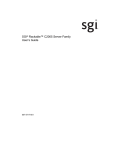
ISS3124-RP2 NAS Server Rear Components Example
The rear panel of the ISS3124-RP2 NAS server (see Figure 1-3) has multiple interface and functional
components as follows:
(A) Power Supply Module #1 and (B) Power Supply Module #2, including the server’s two power
connectors. (C), (D), (E) and (F) are NICs one through four. (G) is the server’s video connector,
(H) is the server’s primary RJ45 Serial-A port and (I) is USB ports 0, 1 and 2. (J) is a
remote-management module (RMM4) NIC port, (K) is an optional I/O module ports/connectors
slot, (L) shows the locations of add-in adapter slots via Riser Card 1 and Riser Card 2 and (M)
shows the location of the Serial-B port (optional).
007-5922-001
3
1: Introduction
Optional IS2224 JBOD Storage
IS2224 JBODs are 2U, rack-mountable storage enclosures based on 6Gb/s SAS technology and
powered by the LSI SAS2x36 6Gb/s SAS expander IC. They offer hot-swappable drive bays that
support 3Gb/s and 6Gb/s SAS hard disk drives (HDDs) or solid-state drives (SSDs). The
following paragraphs and illustrations provide an overview of the IS2224 JBOD; for more detailed
information see the SGI InfiniteStorage IS2224 Installation and Overview Guide, P/N
007-5830-00x.
IS2224 JBOD Front-Panel Features
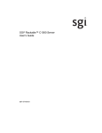
The JBOD storage enclosure has a front control panel (1), slots for up to 24 drives (2) and plastic
end caps as shown in (3) to cover the front-mounting hardware.
1
2
Figure 1-4
3
IS2224 JBOD Storage Enclosure Example (Front View)
The front-panel control LEDs (see callout (1) in Figure 1-4 and also Figure 1-5 on page 5) provide
status and operational information for the JBOD enclosure. Note that during the power-up process
these LEDs may flash intermittently until all sub-systems within the enclosure are fully powered
on. Ensure that all storage enclosures in the system have powered on fully before bringing the
system server online. The indicators have the following functions:
(1) Storage enclosure identifier LED - this blue/white indicator is on for unit identification only
(2) Amber service action required LED
(3) Amber over temperature warning LED
(4) Green “power good” LED lights when the enclosure is fully operational
(5) Green “standby” power mode LED lights when power is available (but unit is not operational)
4
007-5922-001
System Overview
1
2
3
4
5
Figure 1-5
IS2224 JBOD Enclosure Front Status Panel Example
Retention of critical data is enabled by optional, fully redundant and hot-swappable
Environmental Services Modules (ESMs). Each ESM features three 6Gb/s SAS ports, providing
connectivity for two host devices and an expansion port to connect additional JBOD enclosures
via SFF-8088 connections. LEDs on the power supplies, ESMs and each individual drive carrier
allow all system components to be closely monitored to help system administrators ensure storage
integrity. Figure 1-4 on page 4 shows an example rear view of the IS2224 JBOD enclosure.
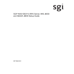
All system power, data interconnect and some status LEDs are located on the back of the system.
007-5922-001
5
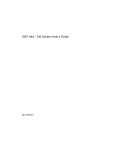
1: Introduction
(1) ESM A canister
(2) Host SFF-8088 connector 1
(3) Host SFF-8088 connector 2
(4) Seven segment display indicators
(5) Serial connector
(6) Ethernet connector
(7) Expansion port SFF-8088 connector
(8) Power/Fan canisters
(9) Power connectors
(10) Power switch locations
(11) ESM B canister location (not installed in this example)
1
2
3
8
Figure 1-6
4
5
6
7
9
10
11
8
9
10
IS2224 JBOD Storage Enclosure Example (Rear View)
Next Steps
Important: Be sure to read the additional safety information related to your SGI NAS system
prior to completing the setup of the hardware, reference Chapter 4, “System Safety.”
6
007-5922-001
System Overview
Un-Racked NAS System Setup
If you need to install and configure the ISS3124 NAS hardware components and cables, go to
Chapter 2, “ISS3124-RP2 Server and IS2224 JBOD NAS System Hardware Installation.”
Continue the drive and cable installation using the subsections that follow in Chapter 2. Finish the
system setup using the information in Chapter 3, “ISS3124-RP2 NAS Operation and GUI
Startup.”
Pre-Racked NAS System Setup
If the system chassis is pre-installed in a rack, system cabling can be confirmed using the example
information in Chapter 2, “ISS3124-RP2 Server and IS2224 JBOD NAS System Hardware
Installation.”. When the system is ready to be plugged in and booted, go to Chapter 3,
“ISS3124-RP2 NAS Operation and GUI Startup.”
007-5922-001
7
Chapter 2
2. ISS3124-RP2 Server and IS2224 JBOD
NAS System Hardware Installation
This chapter provides a hardware setup checklist and instructions to help you get the SGI NAS
system hardware operational. If the NAS hardware is already installed in a rack and cabled
together as a system, continue on to Chapter 3, “ISS3112-RP2 NAS Operation and GUI Startup,”
to start your system hardware and confirm your SGI NAS GUI operation settings.
Unpack the System Enclosures
Inspect the shipping containers that the NAS enclosure(s) were shipped in and note any damage
to the containers or enclosures. If an enclosure shows damage, file a damage claim with the carrier
who delivered it.
Decide on a suitable location for the rack that supports the weight, power requirements, and
environmental requirements of the NAS enclosures. It should be situated in a clean, dust-free
environment that is well ventilated. Avoid areas where heat, electrical noise, and electromagnetic
fields are generated. Place the enclosure rack near a grounded power outlet. Refer to “Warnings
and Precautions” on page 10.
Inspecting a Shipment
It is important that you inspect all equipment received from a shipping carrier before signing for
the shipment. Be sure to do the following when you arrive at a site to install equipment and when
you receive equipment directly from a shipping carrier:
1.
007-5922-001
Inspect the shipment.
•
Does the number of pieces received match the bill of lading?
•
Have boxes been opened or is there damage to the packaging?
•
Has the Tiltwatch indicator been triggered, indicating that the shipment was tipped?
9
2: ISS3124-RP2 Server and IS2224 JBOD NAS System Hardware Installation
•
Has the Tiltwatch indicator been removed?
•
After removing the packaging, is there any visible damage?
2. Record any issues/problems (if applicable):
•
Use the bill of lading to record any issues discovered during the inspection.
•
Sign for the shipment after making notes on the bill of lading.
3. Report the issues to SGI:
Contact the SGI Customer Support Center (CSC) at 1-800-800-4744 (in the United States; refer
to http://www.sgi.com/support/supportcenters.html for international numbers) to begin the
replacement process. Take photos of any damage and in your message, please send a brief
description of the problem to [email protected]. A coordinator will contact you about the problem.
Prepare for Setup
Read the Warnings and Precautions section in its entirety before you begin the installation
procedure.
Choose a Setup Location
Leave enough clearance in front of the rack to enable you to open the front door completely (~25
inches) and approximately 30 inches of clearance in the back of the rack to allow for sufficient
airflow and ease in servicing.
Warnings and Precautions
!
10
Warning: When lifting any of the NAS enclosures, two people (one at each end) should lift
slowly with feet spread apart to distribute the weight. Always follow safe lifting practices
when moving heavy objects, failure to do so may result in serious injury. More information
on moving large objects, requiring a two-person team, is available in the Centers for Disease
Control’s, “Ergonomic Guidelines for Manual Material Handling”
(http://www.cdc.gov/niosh/docs/2007-131/pdfs/2007-131.pdf)
007-5922-001
Warnings and Precautions
!
Warning: Extend the leveling jacks on the bottom of the rack to the floor with the full
!
Warning: Attach stabilizers to the rack in single rack installations. Failure to do so can
!
Warning: Couple racks together in multiple rack installations. Failure to do so can result
!
Warning: Be sure the rack is stable before extending a component from the rack. Failure
!
Warning: Extend only one component at a time. Extending two or more components
weight of the rack resting on them. Failure to do so can result in serious injury or death.
result in serious injury or death.
in serious injury or death.
to do so can result in serious injury or death.
simultaneously may cause the rack to tip over and result in serious injury or death.
Figure 2-1
Slide/Rail Equipment Usage Caution
General Enclosure Precautions
007-5922-001
•
Review the electrical and general safety precautions.
•
Determine the placement of each component in the rack before you install the rails.
11
2: ISS3124-RP2 Server and IS2224 JBOD NAS System Hardware Installation
•
Install the heaviest enclosure components in the bottom of the rack first, and then work up.
•
Use a regulating uninterruptible power supply (UPS) to protect the server from power surges
and voltage spikes and to keep your system operating in case of a power failure.
•
Allow the hot-pluggable drives and power supply modules to cool before touching them.
Rack Mounting Considerations
Use the guidelines in the following subsections when rack mounting servers or JBOD expansion
units.
Ambient Operating Temperature
If installed in a closed or multi-unit rack assembly, the ambient operating temperature of the rack
environment may be greater than the ambient temperature of the room. Therefore, consideration
should be given to installing the equipment in an environment compatible with the manufacturer’s
maximum rated ambient temperature (35º C or 95º F).
Reduced Airflow
Equipment should be mounted into a rack so that the amount of airflow required for safe operation
is not compromised. Always keep the rack’s front door and all panels and components on the
systems closed when not servicing to maintain proper cooling.
Mechanical Loading
Equipment should be mounted into a rack so that a hazardous condition does not arise due to
uneven mechanical loading.
Circuit Overloading
Consideration should be given to the connection of the equipment to the power supply circuitry
and the effect that any possible overloading of circuits might have on over-current protection and
power supply wiring. Appropriate consideration of equipment nameplate ratings should be used
when addressing this concern.
12
007-5922-001
Installing the ISS3124-RP2 NAS Server into a Rack
Reliable Ground
A reliable ground must be maintained at all times. To ensure this, the rack itself should be
grounded. Particular attention should be given to power supply connections other than the direct
connections to the branch circuit (for example, the use of power strips, and so on).
Installing the ISS3124-RP2 NAS Server into a Rack
Use the following steps to install the ISS3124-RP2 NAS server rail kit in the rack.
See the information in “IS2224 JBOD Enclosure Cable Guide and Chassis Location” on page 23
to cable one or more IS2224 JBOD expansion units to the ISS3124-RP2 NAS server.
1.
Attach the ISS3124-RP2 slide rails to the rack as shown in the example in Figure 2-2.
1
2
3
Figure 2-2
007-5922-001
Attaching ISS3124-RP2 Rail Slides to the Rack
13
2: ISS3124-RP2 Server and IS2224 JBOD NAS System Hardware Installation
2. Fully extend the rail slides as shown in the example in Figure 2-3.
Figure 2-3
14
Extending ISS3124-RP2 Rail Slides Example
007-5922-001
Installing the ISS3124-RP2 NAS Server into a Rack
3. Attach the chassis to the rail slides as shown in the example in Figure 2-4.
Figure 2-4
007-5922-001
Attaching Chassis to Rail Slides
15
2: ISS3124-RP2 Server and IS2224 JBOD NAS System Hardware Installation
4. Push the release tab and push the chassis into the rack as shown in the example in Figure 2-5.
2
1
Figure 2-5
16
ISS3124-RP2 Server Chassis Rail Slide Release Tab Example
007-5922-001
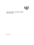
Rackmounting an Optional IS2224 JBOD Enclosure
Rackmounting an Optional IS2224 JBOD Enclosure
Use two people whenever installing the IS2224 JBOD enclosure as the unit can weigh up to 40 lbs
(18.1 kg). Be sure the airflow through the unit matches with other components installed in the
rack, Figure 2-6 shows the airflow pattern from the front (1) to the rear (2).
Figure 2-6
IS2224 JBOD Enclosure Airflow Example
Be sure to read the rackmounting guidelines listed in “Rack Mounting Considerations” on page 12
in this chapter. Use the following steps and illustrations to properly mount the unit in a rack.
007-5922-001
17
2: ISS3124-RP2 Server and IS2224 JBOD NAS System Hardware Installation
Position the IS2224 Mounting Rails
Position the mounting rails in the rack using the following steps, see Figure 2-7 as a reference.
(1) Mounting Rail
(2) Existing Storage Enclosure
(3) Clearance Above and Below the Existing Enclosure
(4) Screws for Securing the Mounting Rail to the Rack rails (Front and Rear)
(5) SGI D-Rack front panel or Industry Standard Cabinet
Figure 2-7
Position the Mounting Rails in the Rack
Tip: If you are installing the mounting rails above an existing storage enclosure, position the
mounting rails directly above the storage enclosure. If you are installing the mounting rails below
an existing storage enclosure, allow 8.8-cm (3.5-in.) vertical clearance for a storage enclosure.
18
007-5922-001
Rackmounting an Optional IS2224 JBOD Enclosure
1.
Attach the mounting rails to the rack by performing these substeps:
–
Make sure that the adjustment screws on the mounting rail are loose so that the
mounting rail can extend or contract as needed.
–
Place the mounting rail inside the cabinet, and extend the mounting rail until the flanges
on the mounting rail touch the inside of the cabinet.
–
Ensure that the alignment spacers on the front flange of the mounting rail fit into the
mounting holes in the cabinet (Figure 2–4 on page 2-6). Note that the front flange of
each mounting rail has two alignment spacers. These alignment spacers are designed to
fit into the mounting holes in the cabinet.The alignment spacers help position and hold
the mounting rail.
(1) Rack Rail Mounting Holes
(2) Adjustment Screws for locking the Mounting Rail Length
(3) Enclosure Mounting Rails
(4) Clip for Securing the Rear of the Storage Enclosure
Figure 2-8
Attaching the Mounting Rails to the Cabinet
Installing the IS2224 Storage Enclosure on the Rails
Figure 2-9 shows an example (1) of the alignment spacers on an IS2224 mounting rail.
007-5922-001
19
2: ISS3124-RP2 Server and IS2224 JBOD NAS System Hardware Installation
Figure 2-9
Alignment Spacers on the IS2224 Mounting Rail
Use the Alignment Spacers to help properly place the rails into the rack and follow these substeps
to secure the rails in place.
1.
Insert one M5 (12mm) screw through the front of the cabinet, and screw into the top
captured nut in the mounting rail.
2. Insert two M5 (12mm) screws through the rear of the cabinet and screw into the captured
nuts in the rear flange in the mounting rail.
3. Tighten the adjustment screws on the mounting rail.
4. Repeat the previous three steps with the additional rail to install the second mounting rail on
the other side of the cabinet.
5. With the help of another person, slide the rear of the enclosure onto the mounting rails.
6. The rear edge of the storage enclosure must fit into the clip on the mounting rail.
7. The storage enclosure is correctly aligned when the following conditions are met on both
mounting rails:
20
007-5922-001
Rackmounting an Optional IS2224 JBOD Enclosure
–
The mounting holes on the front flanges of the storage enclosure align with the
mounting holes on the front of the mounting rails.
–
The rear edge of the storage enclosure sheet metal fits into the clip on the mounting rail
(reference Figure 2-10).
–
The holes in the storage enclosure sheet metal for the rear hold-down screws align with
the captured nuts in the side of the mounting rails.
Mounting rail (1)
Mounting rail clip (2)
Partial view of the storage enclosure’s rear sheet metal (3)
Align hole in the storage enclosure sheet metal with captured nut in the mounting rail (4)
Figure 2-10
Sliding the Storage Enclosure into the Clip on the Mounting Rail
8. Secure the front of the storage enclosure to the cabinet. Use the two screws item (1) in
Figure 2-11 to attach the flange on each side of the front of the storage enclosure to the
mounting rails.
007-5922-001
21
2: ISS3124-RP2 Server and IS2224 JBOD NAS System Hardware Installation
Figure 2-11
Securing the IS2224 Storage Enclosure to the Rack’s Front
9. Insert one M5 (12mm) screw through the bottom hole of a flange on the storage enclosure so
that the screw goes through the rack’s vertical front rail and engages the bottom captured nut
in the mounting rail.
10. Repeat this process for the opposite side of the enclosure and tighten the screws after both
are properly aligned and in place.
11. Secure the enclosure’s plastic front-end caps by referencing Figure 2-12 on page 23 and
performing the following substeps:
–
Put the top of the end cap on the hinge tab (1) that is part of the storage enclosure
mounting flange.
–
Gently press on the bottom of the end cap until it snaps into place over the retainer (2)
on the bottom of the storage enclosure mounting flange.
Note: The left end cap has holes so the LEDs can be seen through them after it is attached to
the storage enclosure.
22
007-5922-001
Rackmounting an Optional IS2224 JBOD Enclosure
Figure 2-12
Attaching End Caps to the IS2224 Storage Enclosure
IS2224 JBOD Enclosure Cable Guide and Chassis Location
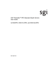
Figure 2-13 shows an example connection between the ISS3124-RP2 and one IS2224 JBOD unit.
Your system may have different options than those shown, check with your service provider.
Figure 2-13
007-5922-001
ISS3124-RP2 NAS Server with One IS2224 JBOD Expansion Cabling Example
23
2: ISS3124-RP2 Server and IS2224 JBOD NAS System Hardware Installation
Figure 2-14 shows example connections between the ISS3124-RP2 and two IS2224 JBOD units.
Figure 2-14
ISS3124-RP2 NAS Server with Two IS2224 JBOD Expansions Cabling Example
Figure 2-15 shows example connections between the ISS3124-RP2 and three IS2224 JBOD units.
24
007-5922-001
Rackmounting an Optional IS2224 JBOD Enclosure
JBOD-A
JBOD-B
JBOD-C
Figure 2-15
ISS3124-RP2 NAS Server with Three IS2224 JBOD Expansions Cabling Example
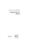
Figure 2-16 shows a cabling example for an ISS3124-RP2 NAS server interconnected with four
IS2224 JBOD expansion units.
007-5922-001
25
2: ISS3124-RP2 Server and IS2224 JBOD NAS System Hardware Installation
JBOD-A
JBOD-B
JBOD-C
JBOD-D
Figure 2-16
26
ISS3124-RP2 NAS Server with Four IS2224 JBOD Expansions Cabling Example
007-5922-001
Supply Power to the System
Check all Cable Connections and Airflow
Make sure all power and data cables are properly connected and not blocking the system airflow.
Check the Airflow
The system component layout was carefully designed to direct sufficient cooling airflow to the
components that generate the most heat.
Note: Make sure that all power and data cables have been routed in such a way that they do not
block the airflow generated by the enclosure fans.
Supply Power to the System
Connect the power cords from all the power supply modules (located at the rear of each enclosure)
into a power strip or power distribution unit (PDU). An optionally available uninterruptible power
supply (UPS) can ensure power availability if primary power fails.
007-5922-001
27
Chapter 3
3. ISS3124-RP2 NAS Operation and GUI Startup
Overview
This chapter covers basic hardware operation and GUI startup for your ISS3124-RP2 NAS
system.
Front Bezel and Control Panels
On the chassis front you can see a control panel (reference Figure 3-1). There is a control panel
on each ISS3124-RP2 NAS head server enclosure. There is also a status/control panel for each
JBOD expansion unit on an SGI NAS.
Figure 3-1
RP2 NAS Head Front Panel Example
Figure 3-2 on page 30 shows an enlarged example of the front control and status panel on the
ISS3124-RP2 NAS server. For more detailed information on the ISS3124-RP2 server see the SGI
Rackable RP2 Standard-Depth Servers User Guide, publication #, 007-5837-00x.
007-5922-001
29
3: ISS3124-RP2 NAS Operation and GUI Startup
Figure 3-2
ISS3124 NAS Server Front Panel Controls and Indicators Example
Table 3-1 describes the control panel components and their functions.
Table 3-1
ISS3124-RP2 Control Panel Components and Functions
Label
Button/LED
Color
Condition
Function
A
System ID button
with LED
Blue
On
Highlights targeted system. Can be activated by the
button or software.
B
NMI button
NIC-x
C, D, I, J Link/Activity
LED
E
30
System Cold
Reset button
Used for diagnostics. Recessed (tool required for
use).
Green
On
Network link to NIC-x detected.
Blink
NIC-x activity detected.
Off
No link.
When pressed, this button reboots and re-initializes
the server.
007-5922-001
Overview
Table 3-1
Label
ISS3124-RP2 Control Panel Components and Functions (continued)
Button/LED
Color
Condition
Function
On
System ready/No alarm.
Blink
System ready, but degraded:
– Redundancy lost such as a pwr supply or fan fail.
– Non-critical temp/voltage threshold.
– Battery failure.
– Predictive power supply failure.
On
Critical Alarm: critical power modules failure,
critical fans failure, voltage (power supply), critical
temperature and voltage
Blink
Non-Critical Alarm: Redundant fan failure,
redundant power module failure, non-critical
temperature and voltage
Off
– Power off: System unplugged.
– Power on: System powered off and in standby, no
prior degraded\non-critical\critical state.
On
Power On/ACPI S0 state
Blink
Sleep/ACPI S1 state
Off
Power Off/ACPI S5 state
On
Hard drives are available.
Blink
Hard drive activity detected.
Off
No hard drives are available.
Green
F
System Status
LED
Amber
G
H
System Power
button with LED
Hard Drive
Activity LED
Green
Amber
Control panel notes:
007-5922-001
•
Blink rate is ~1 Hz at 50% duty cycle.
•
It is also off when the system is powered off (S5) or in a sleep state (S1).
•
The power LED sleep indication is maintained on standby by the chipset. If the system is
powered down without going through the BIOS, the LED state in effect at the time of power
off is restored when the system is powered on until the has BIOS cleared it.
31
3: ISS3124-RP2 NAS Operation and GUI Startup
•
If the system is not powered down normally, it is possible the Power LED will blink at the
same time the system status LED is off due to a failure or configuration change that prevents
the BIOS from running.
ISS3124-RP2 NAS GUI Startup
The SGI ISS3124-RP2 NAS is a software based network attached storage (NAS) appliance that
features unlimited snapshots, snapshot mirroring (replication), NFS v3/v4, optional CIFS, and
easy management of extremely large storage pools. Contact your SGI representative if you need
more information on hardware compatibility.
The information in the following subsections is intended to help start and setup your SGI
ISS3124-RP2 NAS. For more detailed information on using the NAS GUI, see the following
documents:
•
SGI NAS Quick Start Guide, publication number, 007-5865-00x
•
SGI NAS User Guide, publication number, 007-5860-00x
SGI ISS3124-RP2 NAS is pre-configured with administrative user accounts: root and admin. The
default password for both accounts is "nasnas".
Tip: To ensure added security, don't forget to change the system’s default password.
Obtain a Permanent Software License Key
To obtain your permanent software license key for each system running the SGI ISS3124-RP2
NAS software, open an SGI Supportfolio™ case using the following webpage:
https://support.sgi.com/caseview/CreateNewCase
In North America you may also obtain a key by calling 1.800.800.4744.
You must provide the following information to obtain a key:
32
•
Sales Order Number(s)
•
System Serial Number(s)
•
Company Name
007-5922-001
ISS3124-RP2 NAS GUI Startup
•
End User Name
•
Email Address
•
Telephone
Your permanent key(s) will be emailed to you. If your purchase was for add-on plug-ins only, open
a Supportfolio case as described earlier and SGI will upload the functionality for the plug-in to
your original base software key(s).
Registering the SGI ISS3124-RP2 NAS Software
Boot the SGI ISS3124-RP2 NAS appliance. After the appliance boots up, review and accept the
SGI NAS software license agreement.
You can display licensing information in NAS Management View (NMV) by selecting the 'About'
link or use the following NAS Management Console (NMC) command:
nmc:/$ show appliance license
This will indicate whether you are using the trial or commercial edition, and how many days are
left in the case of a trial edition.
After obtaining the commercial license, you can register in NMC using the command:
nmc:/$ setup appliance register
Alternately, you can click on the 'Register' link at the top of the page in NMV. In NMV a form
similar to the following will appear, where you can enter the new license key:
Figure 3-3
007-5922-001
SGI NAS Registration Panel Example
33
3: ISS3124-RP2 NAS Operation and GUI Startup
SGI NAS licenses are based on raw disk drive capacity and log, cache and spare devices are
excluded from the calculation.
Follow the instructions on the appliance’s NAS management console (NMC) screen to register the
appliance software.
Note: The screenshots in this document are examples and may show different configuration
information than what you see. Ensure you enter the product registration key exactly as it appears
in the email sent when you register.
For successful appliance registration, you need to provide a machine “signature”, a unique
9-character code that identifies your machine at the Software License registration page. Figure 3-4
shows an example Software License Agreement Screen, also known as an end-user license
agreement (EULA). Contact SGI to obtain a valid license “Registration Key”.
Figure 3-4
34
NAS Software License Agreement Screen Example
007-5922-001
ISS3124-RP2 NAS GUI Startup
The software key is case sensitive. Make sure to enter the key exactly as specified in the
auto-generated e-mail. The ‘-’ separating groups of key characters needs to be entered as well.
Figure 3-5
Appliance Product Registration Screen Example
Configure the Primary Network Interface
To reconfigure the primary network interface, log in to the system console and execute the setup
appliance init command:
nmc: /$ setup appliance init
Next, you will be prompted to reconfigure the primary network interface. You may opt to choose
DHCP, if your environment supports it, as in Figure 3-6 on page 36. Or, you can set up the
interface statically (you will need to specify the device’s IP address, subnet mask, default gateway,
and DNS server addresses).
007-5922-001
35
3: ISS3124-RP2 NAS Operation and GUI Startup
Tip: In most cases it is preferable to configure the appliance’s primary IP interface statically.
Follow your general local area network administration guidelines.
After you have reconfigured the Primary Network Interface, you should see an “Enabling
message” on the screen similar to:
Enabling ae0 via DHCP...OK.
After choosing your primary IP settings, you need to select no to the reconfigure prompt at the
bottom of the interface screen, see Figure 3-6.
Figure 3-6
Primary Network Interface Selection Screen Example
Choosing SGI NAS Web GUI Transport Protocols
After you have configured the primary network interface, you must choose a transport protocol
for the SGI ISS3124-RP2 NAS WEB GUI (NMV). You can select either HTTP – fast and (plain
text) unsecured, or HTTPS – secured, but less responsive.
36
007-5922-001
ISS3124-RP2 NAS GUI Startup
Figure 3-7 on page 37 shows an example screen with a WEB GUI port selected to 2000 (the
default).
The example screen also shows the primary networking interface and its (configured) settings. At
this point you should be able to ping the appliance from an external host.
Figure 3-7
WEB GUI Protocol and Port Selection Screen Example
Note: During the process of network configuring you can specify the WEB GUI port. The default
is 2000, but you can change it to 2001, 2002 or other ports if they are not being used by other
services. For more info about TCP ports used by the SGI ISS3124-RP2 NAS, see the SGI NAS
User Guide.
At this point the appliance is installed and can be accessed via the appliance’s WEB GUI
“Initial Configuration Wizard”. Figure 3-8 on page 38 shows an example screen pointing the
installer to the Initial Configuration Wizard login.
007-5922-001
37
3: ISS3124-RP2 NAS Operation and GUI Startup
Figure 3-8
Initial Configuration Wizard URL Access Screen Example
You will notice a brief instruction set displayed on the console above the login prompt. It is
essential to follow these instructions and use the internet browser to perform a few basic
configuration steps.
Finishing Initial Configuration
The appliance is now almost ready for use. As per the instructions shown in Figure 3-8, use the
displayed URL (in this example case it is http://192.168.0.251:2000) to connect your browser to
the SGI NAS GUI-based Initial Configuration Wizard. The Wizard will guide you through the
most essential appliance setup steps – for more information refer to the SGI NAS User Guide (P/N
007-5860-00x).
38
007-5922-001
ISS3124-RP2 NAS GUI Startup
Tip: If your internet browser does not connect to the appliance, it is likely because the primary
networking interface is misconfigured. Recheck the procedures you executed in the previous two
subsections. You may be able to fix the configuration by logging in to the console and running the
following command:
nmc:/$ setup appliance init
Preconfigured Storage Pool (Volume)
The appliance is preconfigured with a storage pool or volume, tank0, that is optimized for your
hardware configuration. To view the volume status, log in to the system console and execute the
setup status command:
nmc: /$ setup tank0 status
Use the preconfigured volume to create folders for CIFS or NFS shares or zvols or virtual block
devices for SCSI targets. Refer to the SGI NAS User Guide for further details on managing the
appliance.
007-5922-001
39
Chapter 4
4. System Safety
This chapter describes basic safety precautions for working with the SGI ISS3124-RP2 NAS
systems.
Electrical Safety Precautions
Basic electrical safety precautions should be followed to protect yourself from harm and the
Modular InfiniteStorage system from damage, as follows:
007-5922-001
•
Be aware of the locations of the power on/off buttons on the chassis as well as the room's
emergency power-off switch, disconnection switch or electrical outlet. If an electrical
accident occurs, you can then quickly remove power from the system.
•
Do not work alone when working with high voltage components.
•
Power should always be disconnected from the system when removing or installing main
system components, such as the power supplies and disk drives. When disconnecting power,
you should first power down the operating system and then unplug the power cords. The unit
can have more than one power supply cord. Disconnect all power supply cords before
servicing to avoid electrical shock.
•
When working around exposed electrical circuits, another person who is familiar with the
power-off controls should be nearby to switch off the power if necessary.
•
Use only one hand when working with powered-on electrical equipment. This is to avoid
making a complete circuit, which will cause electrical shock. Use extreme caution when
using metal tools, which can easily damage any electrical components or circuit boards they
come into contact with.
•
Do not use mats designed to decrease static electrical discharge as protection from electrical
shock. Instead, use rubber mats that have been specifically designed as electrical insulators.
•
The power supply power cords must include a grounding plug and must be plugged into
grounded electrical outlets or power distribution unit (PDUs).
41
4: System Safety
NAS Node Serverboard Battery
Caution: There is a danger of explosion if an onboard battery is installed upside down, which
will reverse its polarities (see Figure 4-1). This battery must be replaced only with the same
or an equivalent type recommended by the manufacturer. Check with your service
representative if you have any questions. Dispose of used batteries according to the
manufacturer's instructions.
!
Lithium battery
Battery holder
Figure 4-1
Installing the Onboard Battery
Mainboard Replaceable Soldered-in Fuses
Important: If your system comes with self-resetting PTC (Positive Temperature Coefficient)
fuses on the NAS head node serverboard, they must be replaced by trained service technicians
only. The new fuse must be the same or equivalent as the one replaced. Contact your technical
support organization for details and support.
General Safety Precautions
Follow these rules to ensure general safety:
42
•
Keep the area around the system clean and free of clutter.
•
When lifting the system, two people at either end should lift slowly with their feet spread out
to distribute the weight. Always keep your back straight and lift with your legs.
007-5922-001
ESD Precautions
•
Place the chassis top cover and any system components that have been removed away from
the system or on a table so that they won't accidentally be stepped on.
•
While working on the system, do not wear loose clothing such as neckties and unbuttoned
shirt sleeves, which can come into contact with electrical circuits or be pulled into a cooling
fan.
•
Remove any jewelry or metal objects from your body, which are excellent metal conductors
that can create short circuits and harm you if they come into contact with printed circuit
boards or areas where power is present.
•
After accessing the inside of the system, close the system back up and secure it in the rack
unit after ensuring that all connections have been made.
ESD Precautions
!
Caution: Electrostatic discharge (ESD) is generated by two objects with different electrical
charges coming into contact with each other. An electrical discharge is created to neutralize this
difference, which can damage electronic components and printed circuit boards.
The following measures are generally sufficient to neutralize this difference before contact is
made to protect your equipment from ESD:
007-5922-001
•
Use a grounded wrist strap designed to prevent static discharge.
•
Keep all components and printed circuit boards (PCBs) in their antistatic bags until ready for
use.
•
Touch a grounded metal object before removing the board from the antistatic bag.
•
Do not let components or PCBs come into contact with your clothing, which may retain a
charge even if you are wearing a wrist strap.
•
Handle a board by its edges only; do not touch its components, peripheral chips, memory
modules or contacts.
•
When handling chips or modules, avoid touching their pins.
•
Put the head node serverboard and peripherals back into their antistatic bags when not in use.
•
For grounding purposes, make sure your computer chassis provides excellent conductivity
between the power supply, the case, the mounting fasteners and the serverboard.
43
Chapter 5
5. Troubleshooting Information
This chapter includes basic troubleshooting information and best practice procedures to work with
an SGI ISS3124-RP2 NAS system. This chapter covers the following troubleshooting topics:
•
Detecting Component Failures
•
No Video
•
Loss of System Setup Configuration
•
Safe Power-Off
•
Checking System Air Flow
Note: Some software products are protected with software license keys derived from the
Media Access Control (MAC) Ethernet address. If your system requires the replacement of a
NAS controller head (node) board, the MAC Ethernet address changes. If you are using such
a product, you must request a new license key after replacement of the SGI NAS server node
board. Contact your local customer support office:
http://www.sgi.com/support/supportcenters.html
!
007-5922-001
Caution: Always re-install the chassis cover after you have accessed any internal components to
ensure proper airflow and cooling for the system. Failure to re-install the cover may cause thermal
over-temperature conditions and automatic shut-down of the system.
45
5: Troubleshooting Information
Handling NAS Internal Components
!
Caution: Electrostatic discharge (ESD) can damage electrostatic-sensitive devices inside the
NAS enclosure. Use the ESD precautions described below when you handle printed circuit boards
or other components in the system. The following measures are generally sufficient:
•
Use a grounded wrist strap designed to prevent electrostatic discharge.
•
Touch a grounded metal object before removing any board from its antistatic bag.
•
Handle each printed circuit board (PCB) by the edges; do not touch the components,
peripheral chips, memory modules, or gold contacts on the PCB.
•
When handling any device with exposed chips or modules, avoid touching the pins.
•
Place the NAS head node board, drives, or other boards and components into antistatic bags
when not in use.
•
Make sure your system chassis provides a conductive path between the power supply, the
case, the mounting fasteners, and the node board to chassis ground.
Detecting Component Failures
Use the information in the following subsections to determine if any errors are occurring in the
drives or system power supplies.
ISS3124-RP2 NAS Server Disk Drive LEDs
Figure 5-1 on page 47 shows the location of the drive’s green and yellow disk drive activity and
status LEDs.
46
007-5922-001
Handling NAS Internal Components
Activity LED
Status LED
Figure 5-1
ISS3124-RP2 Disk Drive LEDs
Table 5-1 describes the meaning of the RP2 NAS server’s disk drive status LED.
Table 5-1
LED Color
Amber
RP2 HDD Status LED Functions
LED
Behavior
Drive Status
Off
No access and no fault.
Solid On
Hard drive fault has occurred.
Blink
– RAID rebuild in progress (1Hz). – Identify (2Hz).
Table 5-2 describes the functions of the ISS3124-RP2 disk green drive activity LED.
Table 5-2
LED
Color
Green
007-5922-001
ISS3124-RP2 HDD Activity LED Functions
Drive Condition
Drive
Type
LED Behavior
Power on with no drive activity
SAS
LED stays on.
Power on with drive activity.
SAS
LED blinks off when processing a command.
Power on and drive spun down
SAS
LED stays off.
Power on and drive spinning up
SAS
LED blinks.
47
5: Troubleshooting Information
ISS3124-RP2 Server Power Supply LEDs
There is a single bi-color LED (green/amber) to indicate the ISS3124-RP2 server power supply
status. Table 5-3 describes the different states of the LED.
Table 5-3
ISS3124-RP2 Power Supply LED States
LED State
Power Supply (PS) State
Off
No AC power to any PS.
Green
Output on and Ok.
Green, 1Hz blink
AC present (only 12VSB on). PS off or PS in cold redundant state.
Green, 2Hz blink
PS firmware updating.
Amber
– PS critical event causing a shutdown/failure (OCP, OVP, fan failure) –
AC cord unplugged or AC power lost. A second power supply in parallel
still has AC input power.
Amber, 1Hz blink
PS warning events where the power supply continues to operate (high
temperature, high power, high current, slow fan).
No Video After Power-On
If the power is on and the system has had adequate time to boot, but there is no video, check all
add-on cards and cables. Tighten or re-plug any loose cable connections. Be sure your monitor is
powered up and switched to the On position.
Use the speaker to determine if any beep codes exist. Refer to Appendix A, “BIOS Error Codes”
for details.
If video output is still absent, check with your system administrator or service provider.
Loss of System Setup Configuration
Make sure that your power supplies are operating properly, see “No Video After Power-On” on
page 48 for guidelines. An improperly operating power supply may cause the system to lose the
CMOS setup information. If this does not fix the Setup Configuration problem, consult your
system administrator or contact your service organization for repairs.
48
007-5922-001
Handling NAS Internal Components
Safe Power-Off
There are several safe power-off methods for an SGI NAS Server or JBOD. They include,
•
Using the OS GUI power-off button at the console screen, if a keyboard/mouse/video
monitor is connected.
•
Pushing and holding the Power button on the front panel (see “Front Bezel and Control
Panels” in Chapter 3).
•
When logged in via an ssh session and executing a “shutdown” or “poweroff”
command.
•
When logged in to the BMC and using the power control page to power off the sever.
•
Using the remote console screen GUI power-off button, if a KVM RMM4Lite session is
established through the BMC.
For an IS2224 NAS JBOD Unit, the power button on the front panel will turn off the power to that
I/O module. If an additional JBOD module is installed and powered on, it, the fans and the drives
will remain on until it, too, is powered off.
Checking System Airflow
Ensure that rack internal cabling is not blocking the front or rear airflow through the NAS server
or JBOD units. Reduced airflow may cause an over-temperature (overtemp) condition in the NAS
server or JBOD enclosures.
Important: Failing to keep the enclosure cover(s) in place during operation may cause airflow
interruption to critical internal components and consequent overheating and shutdown.
Leave enough clearance in front of the rack to enable you to open the front door completely (~25
inches) and approximately 30 inches of clearance in the back of the rack to allow for sufficient
airflow and ease in servicing.
007-5922-001
49
Appendix A
A. BIOS Error Codes
During Power-On Self-Test (POST) routines, which are performed each time the system is
powered on, errors may occur. Non-fatal errors are those which, in most cases, allow the system
to continue the boot-up process. The error messages normally appear on the screen.
The BMC may generate beep codes upon detection of failure conditions that do not allow the
system to fully boot. Beep codes are sounded each time the problem is discovered (for example,
on each power-up attempt) but are not sounded continuously. Common supported codes are listed
in Table A-1.
In Table A-1, each digit in the code is represented by a sequence of beeps whose count is equal to
the digit.
Table A-1
007-5922-001
BMC Beep Codes
Associated
Sensors
Supported
No CPUs installed or first CPU socket is
empty.
CPU Missing sensor
Yes
1-5-2-4
MSID Mismatch.
MSID Mismatch
sensor.
Yes
1-5-4-2
Power fault: DC power is unexpectedly
lost (power good dropout).
Power unit—power
unit failure offset.
Yes
1-5-4-4
Power control fault (power good assertion
time-out).
Power unit—soft
power control failure
offset.
Yes
1-5-1-2
VR Watchdog Timer sensor assertion
VR Watchdog timer
1-5-1-4
The system does not power on or
unexpectedly powers off and a power
supply unit (PSU) is present that is an
incompatible model with one or more
other PSUs in the system.
PSU status
Beep Code
Reason for Beep
1-5-2-1
51
Appendix B
B. System Specifications and Regulatory Overview
This appendix provides basic environmental operating requirements and regulatory information
for the ISS3124-RP2 NAS server and IS2224 JBOD disk expansion.
Operating Environment
Table B-1 describes the technical specifications for the ISS3124-RP2 NAS server.
Table B-1
007-5922-001
ISS3124-RP2 NAS Server Environmental Specifications
Attribute
Specifications
Operating temperature
+10ºC to +35ºC with the maximum rate of change not to exceed 10ºC per hour
Non-operating
temperature
-40ºC to +70ºC with the maximum rate of change not to exceed 20ºC per hour
Non-operating humidity
90%, non-condensing at 35ºC
Acoustic noise/Sound
power
7.0 BA in operating condition at typical office ambient temperature
(23ºC +/– 2ºC).
Shock, operating
Half sine, 2 g peak, 11 milliseconds
Shock, unpackaged
Trapezoidal, 25 g, velocity change 136 inches/second (40 lbs to less than 80
lbs)
Shock, packaged
Non-palletized free fall in height 24 inches (40 lbs to less than 80 lbs)
Vibration, unpackaged
5 Hz to 500 Hz, 2.20 g RMS random
ESD
+/-12 KV, except I/O port +/- 8 KV per test specification
System cooling
requirement in BTU/Hr
460 Watt Max – 1570 BTU/hour
750 Watt Max – 2560 BTU/hour
Maximum weight
100 lbs (45 kg)
53
B: System Specifications and Regulatory Overview
Table Table B-2 outlines the operating environment and specifications for the IS2224 JBOD disk
enclosures.
Table B-2
IS2224 JBOD Enclosure Operating and Environmental Specifications
Attribute
Specifications
Operating temperature
+5ºC to +45ºC (up to 6,000 feet) +5ºC to +35ºC (6,000-10,000 feet) with the
maximum rate of change not to exceed 10ºC per hour
Non-operating
temperature
-10ºC to +50ºC with the maximum rate of change not to exceed 20ºC per hour
Transit temperature range -40ºC to +60ºC
Operating humidity
20% to 80%
Non-operating humidity
10% to 90%, non-condensing at 35ºC
Transit humidity range
5% to 95%
Enclosure weights
59.5 lbs (27.1 kg) [shipping weight 70 lbs (31.8 kg)]
Enclosure power supplies 585 W maximum per supply (2 per enclosure)
Chassis Dimensions
Height
3.47" (88 mm)
Width
17.7" (449 mm)
Depth
19.2" (487 mm)
Regulatory Compliance
Electromagnetic Emissions: FCC Class A, EN 55022 Class A, EN 61000-3-2/-3-3, CISPR 22
Class A
Electromagnetic Immunity: EN 55024/CISPR 24, (EN 61000-4-2, EN 61000-4-3,
EN 61000-4-4, EN 61000-4-5, EN 61000-4-6, EN 61000-4-8, EN 61000-4-11)
Safety: CSA/EN/IEC/UL 60950-1 Compliant, UL or CSA Listed (USA and Canada), CE Marking
(Europe)
54
007-5922-001
Regulatory Compliance
California Best Management Practices Regulations for Perchlorate Materials: This Perchlorate
warning applies only to products containing CR (Manganese Dioxide) Lithium coin cells.
“Perchlorate Material-special handling may apply. See
www.dtsc.ca.gov/hazardouswaste/perchlorate”
007-5922-001
55