1
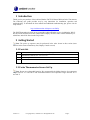
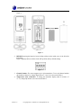
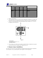
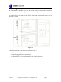
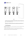
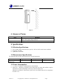
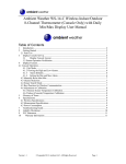
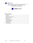
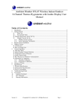
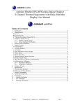
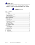
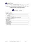
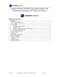
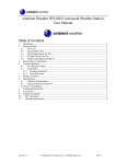
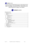
Ambient Weather F007TP 8-Channel Wireless Probe Thermometer User Manual Table of Contents 1 2 3 4 5 6 7 8 9 Introduction ..................................................................................................................................... 2 Getting Started ................................................................................................................................ 2 2.1 Parts List ....................................................................................................................................... 2 2.2 Probe Thermometer Sensor Set Up ............................................................................................... 2 Remote Sensor Installation ............................................................................................................. 4 3.1 Refrigerator/Freezer Mounting............................................................................................... 5 3.2 Wall Mounting .............................................................................................................................. 6 Glossary of Terms ........................................................................................................................... 7 Specifications .................................................................................................................................. 7 5.1 Wireless Specifications ................................................................................................................. 7 5.2 Measurement Specifications ......................................................................................................... 7 5.3 Power Consumption ...................................................................................................................... 7 Troubleshooting Guide.................................................................................................................... 8 Liability Disclaimer ........................................................................................................................ 8 FCC Statement ................................................................................................................................ 9 Warranty Information ...................................................................................................................... 9 Version 1.0 ©Copyright 2013, Ambient LLC. All Rights Reserved. Page 1 1 Introduction Thank you for your purchase of the Ambient Weather F007TP 8-Channel Wireless Probe Thermometer. The following user guide provides step by step instructions for installation, operation and troubleshooting. To download the latest manual and additional troubleshooting tips, please visit the FAQ website: http://ambientweather.wikispaces.com/f007tp The F007TP transmits wirelessly to any compatible Ambient Weather receiver, including the WS-07, WS-08, WS-09 and WS-10 wireless weather station display consoles. Other console models may be added later, and will be listed on the FAQ website. 2 Getting Started Note: The power up sequence must be performed in the order shown in this section (insert batteries in the remote transmitter(s) first, Display Console second). 2.1 Parts List QTY 1 2 3 Item Probe thermometer transmitter with probe (FT007TP) Dimensions (LxHxW): 4.5” x 2.0” x 0.75” Suction cup mounts User Manual 2.2 Probe Thermometer Sensor Set Up Note: Do not use rechargeable batteries. We recommend fresh alkaline batteries for temperature ranges between -4 °F and 140 °F and fresh lithium batteries for temperature ranges between -40 °F and 140 °F. Version 1.0 ©Copyright 2013, Ambient LLC. All Rights Reserved. Page 2 1. Remove the battery door on the back of the sensor by removing the set screw, as shown in Figure 1 . Figure 1 2. BEFORE inserting the batteries, locate the dip switches on the inside cover of the lid of the transmitter. Figure 2 displays all four switches in the OFF position (factory default setting). Figure 2 3. Channel Number: The sensor supports up to eight transmitters. To set each channel number (the default is Channel 1), change Dip Switches 1, 2 and 3, as referenced in Table 1. 4. Temperature Units of Measure: To change the transmitter display units of measure (°F vs. °C), change Dip Switch 4, as referenced in Table 1. Version 1.0 ©Copyright 2013, Ambient LLC. All Rights Reserved. Page 3 1 DOWN DOWN DOWN DOWN UP UP UP UP ----- DIP SWITCH 2 3 DOWN DOWN DOWN UP UP DOWN UP UP DOWN DOWN DOWN UP UP DOWN UP UP --------- FUNCTION 4 ----------------DOWN UP Channel 1 Channel 2 Channel 3 Channel 4 Channel 5 Channel 6 Channel 7 Channel 8 °F °C Table 1 5. Insert two AAA batteries. 6. After inserting the batteries, the remote sensor LED indicator will light for 4 seconds, and then flash once per 60 seconds thereafter. Each time it flashes, the sensor is transmitting data. 7. Verify the correct channel number (CH) and temperature units of measure (°F vs. °C) are on the display, as shown in Figure 3. Figure 3 (1) temperature (2) temperature units (°F vs. °C) (3) channel number 8. Close the battery door. Make sure the gasket (around the battery compartment) is properly seated in its trace prior to closing the door. Tighten the set screw. 3 Remote Sensor Installation The remote probe sensors have many applications, including measuring inside/outside air temperature, water temperature, soil or ground temperature and refrigerator / freezer temperatures. Version 1.0 ©Copyright 2013, Ambient LLC. All Rights Reserved. Page 4 3.1 Refrigerator/Freezer Mounting The sensor includes a detachable suction cup that may be used to secure the remote sensor to the interior or exterior surface of the refrigerator/freezer, as shown in Figure 4. For better reception, we recommended installing the sensor to the outside of the refrigerator/freezer. If the refrigerator/freezer is a metal box, the wireless signal cannot escape, and the sensors must be placed on the outside. Figure 4 To attach the suction cup to the remote sensor, reference Figure 5. 1. 2. 3. 4. Locate the mounting hole on the back of the unit. Press the suction cup into the mounting hole. While applying pressure with your thumb, twist the suction cup until fully inserted. Wet the back of the suction cup and apply to clean, smooth, flat surface. Version 1.0 ©Copyright 2013, Ambient LLC. All Rights Reserved. Page 5 Figure 5 Note: The sensor have the capability of being placed inside or outside the refrigerator/freezer, but it is recommended you install it outside. This will extend the battery life, the sensor life, and improve wireless communication range. Note: Make sure that the refrigerator surface is smooth and clean, so that suction cups will not fall off. It is recommended to wet the surface of the suction cup first to improve the seal. 3.2 Wall Mounting The remote sensor can be mounted to a wall or horizontal surface to measure any temperature medium, including air, water and soil. Use a screw or nail (not included) to affix the remote sensor to the wall, as shown in Figure 6. Note: If measuring outside air temperature, we recommend mounting the sensor in the shade, on the north side of the house or structure to avoid radiant heat transfer. Version 1.0 ©Copyright 2013, Ambient LLC. All Rights Reserved. Page 6 Figure 6 4 Glossary of Terms Term Accuracy Range Definition Accuracy is defined as the ability of a measurement to match the actual value of the quantity being measured. Range is defined as the amount or extent a value can be measured. 5 Specifications 5.1 Wireless Specifications Line of sight wireless transmission (in open air): 150 feet, 100 feet under most conditions. Frequency: 433 MHz Update Rate: 60 seconds 5.2 Measurement Specifications The following table provides specifications for the measured parameters. Measurement Channel 1-8 Temperature Range -40 to 140 °F Accuracy ± 1 °F Resolution 0.1 °F 5.3 Power Consumption 2 x AAA 1.5V Alkaline or Lithium batteries (not included) Battery life: Minimum 12 months for base station with one sensor and excellent reception. Intermittent reception and multiple sensors may reduce the battery life. Minimum 12 months for thermometer probe sensor (use lithium batteries for temperatures less than -4 °F) Version 1.0 ©Copyright 2013, Ambient LLC. All Rights Reserved. Page 7 6 Troubleshooting Guide If your question is not answered here, you can contact us as follows: 1. Email Support: [email protected] 2. Live Chat Support: www.ambientweather.com/chat.html (M-F 8am to 4pm Arizona Time) 3. Technical Support: 480-346-3380 (M-F 8am to 4pm Arizona Time) Problem Wireless remote not reporting in to console. There are dashes (--.-) on the display console. Solution The maximum line of sight communication range is 150’ and 100’ under most conditions. Move the sensor closer to the display console. If the sensor assembly is too close (less than 5’), move the sensor assembly away from the display console. Make sure the remote sensor LCD display is working and the transmitter light is flashing once per 60 seconds. Install a fresh set of batteries in the remote thermometer. For cold water environments, install lithium batteries. Make sure the remote sensors are not transmitting through solid metal (acts as an RF shield), or earth barrier (down a hill). LCD display fading or unreadable. Move the display console around electrical noise generating devices, such as computers, TVs and other wireless transmitters or receivers. Replace batteries in the thermometer. Extreme heat or cold will cause the display to fade but does not affect the wireless functionality. Bring into house to restore display. 7 Liability Disclaimer Please help in the preservation of the environment and return used batteries to an authorized depot. The electrical and electronic wastes contain hazardous substances. Disposal of electronic waste in wild country and/or in unauthorized grounds strongly damages the environment. Reading the “User manual” is highly recommended. The manufacturer and supplier cannot accept any responsibility for any incorrect readings and any consequences that occur should an inaccurate reading take place. This product is designed for use in the home only as indication of weather conditions. This product is not to be used for medical purposes or for public information. The specifications of this product may change without prior notice. This product is not a toy. Keep out of the reach of children. Version 1.0 ©Copyright 2013, Ambient LLC. All Rights Reserved. Page 8 No part of this manual may be reproduced without written authorization of the manufacturer. Ambient, LLC WILL NOT ASSUME LIABILITY FOR INCIDENTAL, CONSEQUENTIAL, PUNITIVE, OR OTHER SIMILAR DAMAGES ASSOCIATED WITH THE OPERATION OR MALFUNCTION OF THIS PRODUCT. 8 FCC Statement Statement according to FCC part 15.19: This device complies with part 15 of the FCC rules. Operation is subject to the following two conditions: 1. This device may not cause harmful interference. 2. This device must accept any interference received, including interference that may cause undesired operation. Statement according to FCC part 15.21: Modifications not expressly approved by this company could void the user's authority to operate the equipment. Statement according to FCC part 15.105: NOTE: This equipment has been tested and found to comply with the limits for a Class B digital device, pursuant to Part 15 of the FCC Rules. These limits are designed to provide reasonable protection against harmful interference in a residential installation. This equipment generates, uses and can radiate radio frequency energy and, if not installed and used in accordance with the instructions, may cause harmful interference to radio communications. However, there is no guarantee that interference will not occur in a particular installation. If this equipment does cause harmful interference to radio or television reception, which can be determined by turning the equipment off and on, the user is encouraged to try to correct the interference by one or more of the following measures: • Reorient or relocate the receiving antenna. • Increase the separation between the equipment and receiver. • Connect the equipment into an outlet on a circuit different from that to which the receiver is connected. • Consult the dealer or an experienced radio/TV technician for help. 9 Warranty Information Ambient, LLC provides a 1-year limited warranty on this product against manufacturing defects in materials and workmanship. This limited warranty begins on the original date of purchase, is valid only on products purchased and only to the original purchaser of this product. To receive warranty service, the purchaser must contact Ambient, LLC for problem determination and service procedures. Warranty service can only be performed by a Ambient, LLC. The original dated bill of sale must be presented upon request as proof of purchase to Ambient, LLC. Your Ambient, LLC warranty covers all defects in material and workmanship with the following specified exceptions: (1) damage caused by accident, unreasonable use or neglect (lack of reasonable and necessary maintenance); (2) damage resulting from failure to follow instructions contained in your owner’s manual; (3) damage resulting from the performance of repairs or alterations by someone other than an authorized Ambient, LLC authorized service center; (4) units used for other than home use (5) applications and uses that this product was not intended (6) the products inability to receive a signal Version 1.0 ©Copyright 2013, Ambient LLC. All Rights Reserved. Page 9 due to any source of interference or metal obstructions and (7) extreme acts of nature, such as lightning strikes or floods. This warranty covers only actual defects within the product itself, and does not cover the cost of installation or removal from a fixed installation, normal set-up or adjustments, claims based on misrepresentation by the seller or performance variations resulting from installation-related circumstances. Version 1.0 ©Copyright 2013, Ambient LLC. All Rights Reserved. Page 10