1
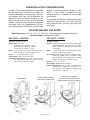
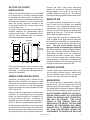
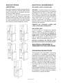
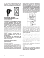
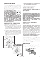
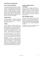
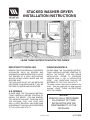
STACKED WASHER-DRYER
INSTALLATION INSTRUCTIONS
LEAVE THESE INSTRUCTIONS WITH THE OWNER
IMPORTANT TO INSTALLER
CANADIAN MODELS
REMOVE THE DOOR FROM ALL DISCARDED
APPLIANCES SUCH AS DRYERS AND
COMBINATION WASHER/DRYERS TO AVOID
THE DANGER OF A CHILD SUFFOCATING
SHOULD HE/SHE CRAWL INSIDE AND THE
DOOR BE SHUT.
PLEASE READ THE FOLLOWING INSTRUCTIONS CAREFULLY BEFORE STARTING TO
INSTALL THE DRYER. FOR GAS DRYER
INSTALLATION, REFER TO STANDARD
CAN/CGA B149 (.1 OR .2) INSTALLATION
CODE.
ANY QUESTIONS SHOULD BE
REFERRED TO THE LOCAL GAS UTILITY.
THE APPLIANCE MUST NOT BE INSTALLED
OR STORED IN AN AREA WHERE IT WILL BE
EXPOSED TO WATER AND/OR WEATHER.
U.S. MODELS
PLEASE READ THE FOLLOWING INSTRUCTIONS CAREFULLY BEFORE STARTING TO
INSTALL THE DRYER. FOR GAS DRYERS,
THE INSTALLATION MUST CONFORM WITH
THE NATIONAL FUEL GAS CODE ANSI
Z223.1, LATEST REVISION. ANY QUESTIONS
CONCERNING THIS SHOULD BE REFERRED
TO THE LOCAL GAS UTILITY.
This folder contains information of interest to the
owner. After the appliance has been properly
installed, LEAVE THESE INSTRUCTIONS
WITH THE OWNER.
NOTICE:
SERVICE CALLS PERFORMED
AS A RESULT OF POOR
INSTALLATION ARE THE
RESPONSIBILITY OF THE
INSTALLER.
printed in U.S.A.
6 3717020
IMPORTANT TO OWNER
Retain these instructions for future reference.
This new Maytag appliance is designed to serve
you dependably for many years. However, it
cannot do so unless provided with sufficient
electrical power, suitable exhausting and if a gas
model, adequate gas supply. We urge you to
read this carefully to make sure all requirements
are met.
Operating instructions, safety precautions and
your warranty are in the accessory package with
each appliance. Read the operating instructions
carefully.
NOTE: A wiring diagram for the dryer is located
on the inside of the dryer access panel. A wiring
diagram for the washer is located on the inside
of the washer cabinet.
Untape and open washer lid. Remove installation accessory package, fill hoses and close lid.
Leave tub block in place until installation is
complete. Be sure to remove tub block after
installation is complete and before use!
Using the carton corner posts stacked in pairs,
lay the washer on the posts on the left side.
Remove the crate base wires from the carton
base. Use pliers or screwdriver to pry wires from
wood. (Do not kick the shipping base off the
washer.)
Run washer rear legs all the way up into the rear
corner brackets. Lock in place by tightening lock
nuts up against base. Leave front legs loose for
leveling later.
UNCRATING
To remove carton, cut around bottom of carton
on or below dotted line. Cut down each corner
of carton (vertically) and “peel” carton away from
stacked washer/dryer. Fold carton material for
removal. Check the unit for shipping damage.
Install the vinyl feet on the washer legs.
Remove the tape between the washer cabinet
and the dryer stand. Disconnect the control wire
harness which leads from the dryer to the
washer. You will need to depress the locking
tabs to separate the connector.
Lay a piece of the shipping cardboard along the
bottom edge of the cabinet and stand the washer
back up. (The cardboard protects the lower
edge at the cabinet and the floor when standing
the washer back up.)
From the back of the stacked washer/dryer,
grasp the dryer and stand. Pull dryer and stand
back and off of washer and shipping base. As
dryer and stand are pulled back, carefully drop
dryer stand rear legs to
the floor before clearing
shipping base. (Do not
drop dryer and stand
off of shipping base!)
NOTE: With the rear washer legs adjusted up,
cabinet corner brackets in the rear can touch
and damage floor if caution is not used when
moving washer.
The dryer and stand are installed first.
Necessary electrical, gas (if gas stacked washer/
dryer) and vent connections are made as dryer
and stand are put in position and leveled. Let’s
first look at what facilities are needed.
printed in U.S.A.
1
PREINSTALLATION CONSIDERATIONS
Location: The stacked washer/dryer is approved
for zero clearance installation on the sides and
the back (depending on venting used). The location selected must take into consideration the
dimensions of the unit and convenience for customer use and access in case service should be
needed. The floor must be capable of supporting
the weight of the unit (approximately 310 lbs.)
plus water (approximately 150 lbs.) and be stable
enough to prevent excessive vibration in spin
cycles. A floor which is adequate for the
standard washer is sufficient for the stacked
washer/dryer.
The following specifications and drawings show
dimensions and locations of fill valve, terminal
block (electric dryer), gas inlet (gas dryer) and
drain outlet.
STACKED WASHER AND DRYER
Basic Dimensions: 27 1/2 W x 27 1/2 D x 73 H (min.) See drawings for complete dimensions.
Uncrated Weight: Approximately 310 lbs.
KEY FACTS – WASHER
KEY FACTS – DRYER
Capacity: Standard (16 gal.)
Air Flow: 180CFM
Water Usage: (full cycle)
36 (30 Imp.) gal.; 136 liters – large
28 (23 Imp.) gal.; 106 liters – medium
22 (18 Imp.) gal.; 83 liters – small
Exhaust: 4″ duct permits up to a maximum of 50 feet rigid
aluminum ductwork. Subtract 8 feet for each 90°
elbow, 8 feet for an exhaust hood. Dryer vented
out the back.
Motor: 1/2 H.P. rated; 120 volt; 60 Hz; reversible, thermoprotected against overload; automatic reset.
Motor:
Power: .1 – .17 kwh depending on cycle
Heat Source: Electric-Nichrome helix coil, 240 volt 3-wire,
4600 watts, (4500 wats for Canadian models
only), 30 amp fuse. Gas-single port burner 18000
BTU/hr.; electric ignition; automatic shut-off.
Hose Lengths: Inlet 4.0 feet, drain 4 feet
Installation Requirements: Hot and cold connections
with water pressure within 20 – 120 PSI range. At
least 140°F. hot water and a drain.
1/4 H.P. rated; 115 volt; 60 Hz thermoprotected
against overload; automatic reset.
Capacity: 4.7 cu. ft., .13 cu. m.
Drum Speed: Approximately 47.5 RPM
Electrical Requirements: Electric Dryer – 240 volt 60 Hz
protected by a 30 amp fuse. Gas Dryer – 115
volt electrical outlet properly grounded and
protected by a 15 amp fuse.
DIMENSIONS
2
INSTALLATION SHOWING
GAS DRYER CONNECTION
printed in U.S.A.
INSTALLATION SHOWING
ELECTRICAL/WATER/DRAIN BOX
BEHIND WASHER-ELECTRIC DRYER
ALCOVE OR CLOSET
INSTALLATION
When the stacked washer/dryer is to be installed
in an alcove area or a closet, clearance should
be provided around the unit for an adequate air
supply and for ease of installation and servicing.
An appliance installed in a closet shall have no
other fuel burning appliance installed in the
same closet, such as gas furnace, water heater
or space heater, etc.
The dryer must be exhausted to the outside to
minimize excessive lint accumulation and to
maintain good drying. We recommend allowance for more clearance than the minimum
installation clearances as shown.
Ceiling
Closet Door
3"
6"
36 Sq. In.
Opening
0"
0"
3"
FRONT VIEW
1/2"
SIDE
VIEW
Each opening area must have a minimum of 36
square inches. These openings must not be
obstructed. (Louvered door with equivalent air
opening is acceptable.)
MOBILE HOME INSTALLATION
Installation of Maytag dryers certified by the
American Gas Association and bearing a label
stating they are suitable for installation in mobile
homes, must conform to the Manufactured
Home Construction and Safety Standard Title 24
CFR, Part 32-80.
When installing this appliance in a mobile home,
provisions for anchoring the dryer should be
made. An anchor bracket kit is available to fasten dryer stand to the floor. Instructions for
installing the anchor brackets are contained in
each kit. (See your authorized Maytag dealer.)
All mobile home installations must be exhausted
to the outside with the exhaust duct termination
securely fastened to the mobile home structure,
using materials that will not support combustion.
Exhaust the dryer using metal exhausting
material or exhaust kit (see your authorized
Maytag dealer), and locate in an area that
provides adequate make-up air. The exhaust
duct may not terminate beneath the mobile home.
MAKE-UP AIR
For proper operation of the dryer unit it is important to make sure the location has adequate
make-up air. This is especially important in any
confined area such as bathroom or closet. There
must be at least two 36 square inch unobstructed
openings for intake air. This can be a louvered
door or other equivalent opening.
On gas dryer units in particular, adequate clearance as noted on the dryer minimum clearance
label should be maintained to insure enough air
for combustion and the proper operation of the
dryer. The area where located must not
obstruct the flow of combustion or ventilating
air. When installing a Maytag Stacked Washer/
Dryer the following minimum clearances to
combustible surfaces must be maintained.
Clearance to wall, sides – 0 inches, top – 6 inches,
front – 1/2 inch to washer, rear – 0 inches with an
outside exhaust, 4 inches with an inside exhaust
(not recommended). See Exhausting section and
Installation Accessories for exhaust kits.
SERVICE ACCESS
Location should allow access to the front of the
unit for washer and dryer service. Access must
also be available to two screws at the top front
corners of the dryer front panel (on the top).
EXHAUSTING
The free air flow rate is approximately 180 cubic
feet per minute. The vent system carries lint and
moisture away and to the outside. The length of
the venting and the number of elbows affect the
air flow rate and the efficiency of the exhaust system.
DO NOT EXHAUST DRYER INTO ANY WALL,
CEILING, CRAWL SPACE OR A CONCEALED
SPACE OF A BUILDING, VENT CONNECTION,
GAS VENT OR CHIMNEY. THIS COULD
CREATE A FIRE HAZARD FROM LINT
EXPELLED BY THE DRYER. FOR THE SAME
REASON, WE RECOMMEND ONLY METAL
EXHAUST DUCT TO MINIMIZE RESTRICTED
AIR FLOW AND RELIABLY INSURE THE
CONTAINMENT OF EXHAUST AIR, HEAT AND
printed in U.S.A.
3
LINT. NEVER INSTALL A SCREEN OVER
EXHAUST OUTLET. NEVER USE PLASTIC OR
OTHER COMBUSTIBLE DUCTWORK. AT
LEAST ONCE A YEAR, INSPECT AND CLEAN
INTERIOR OF DUCTWORK. FREQUENTLY
CHECK AND CLEAN VENT HOOD TO ASSURE
PROPER OPERATION.
A clothes dryer produces combustible lint and
the area around the clothes dryer should be kept
free of lint. DO NOT STORE FLAMMABLE
LIQUIDS OR MATERIALS NEAR A DRYER.
It is recommended that the dryer be exhausted
to the outside using 4 inch rigid or flexible metal
ducting.
When located in a bedroom, bathroom or closet,
the dryer must be exhausted to the outside.
The stacked washer/dryer can only be exhausted out the back. A 4 inch vent should be
installed to accept the exhaust from the dryer.
To permit sufficient air circulation under the
exhaust hood, there should be no less than a 12
inch clearance between the bottom of the
exhaust hood and the ground. When possible
the exhaust hood should not exhaust directly
into a window well. DO NOT terminate exhaust
under a building.
NOTE: Where the exhaust hood is to be
installed through masonry, a special masonry
saw is necessary to cut the hole.
DIRECT EXHAUST
An exhaust hood positioned to line up with the
dryer exhaust pipe can be installed directly
through an outside wall. This would be the
shortest and most direct exhaust method.
To exhaust up, route standard 4 inch diameter
ducting up the recess in the cabinet back using
the furnished retaining strap and screws to get
nearly flush to wall installation. To exhaust to the
side or down, install the furnished 4 inch long
duct with four “S” clips to the inner dryer exhaust,
then use standard 4 inch ducting. This will position the dryer about 4-1/2 inches away from the
wall. Flush-to-wall side exhausting may be done
by going above the dryer before going sideways.
When exhausting down, wallboard can be
removed from the wall to get the dryer closer to
the wall by placing the exhaust pipe between
studs. Check local codes for required
exhaust clearances.
Install ductwork from the dryer to exhaust hood.
All joints must be made so exhaust end of one
pipe is inside the intake end of next pipe. On
flexible metal ductwork, all joints should be
secured with a clamp. DO NOT use sheet metal
screws when assembling rigid ducting. Joints
should be taped.
Install the exhaust hood and secure with screws
to the outside wall and seal with caulking compound.
EXHAUST HOOD TYPE
Number of
90° Turns
FLEXIBLE DUCTWORK
LIMITATIONS
4
2 1/2
inch
inch
Maximum length of 4 inch diameter
rigid metal duct
0
54 feet
44 feet
1
43 feet
33 feet
2
36 feet
26 feet
3
30 feet
20 feet
4
24 feet
14 feet
Maximum length of 4 inch diameter
flexible stiff walled metal duct
0
34 feet
27 feet
1
26 feet
19 feet
2
22 feet
17 feet
3
18 feet
15 feet
4
15 feet
13 feet
4
Flexible metal ductwork should not exceed 34
feet of straight 4 inch ducting. The exhaust hood
is equivalent to 8 feet of duct and each 90° bend
is equivalent to 8 feet. As an example, if an
exhaust hood is used and two 90° bends, the
maximum straight run would be 10 feet.
NOTE: If the radius of a bend with 4 inch duct is
12 inches or greater, the bend can be considered
a straight run. No more than three 90° bends
should be used in any run with an exhaust hood.
If flexible metal exhaust ducting is used, the short
extension supplied with this machine can be
secured to the dryer exhaust with the clips and
the flexible metal duct can be clamped to the
short extension.
printed in U.S.A.
RIGID DUCTWORK
LIMITATIONS
ELECTRICAL REQUIREMENTS
IMPORTANT SAFETY PRECAUTIONS
Rigid metal ductwork should not exceed 54 feet
of straight 4 inch duct. Each 90° elbow and the
exhaust hood should be considered equivalent
to 8 feet of straight ductwork.
For example, if an exhaust hood and two 90°
elbows are used, the maximum straight duct
allowed would be 26 feet. Not more than three
90° elbows should be used in any rigid ductwork
run with an exhaust hood. Four feet of straight
duct should be allowed between 90° elbows.
WARNING: To prevent unnecessary risk of fire,
electrical shock or personal injury, all wiring and
grounding must be done in accordance with
local codes, or in the absence of local codes,
with the National Electrical Code, ANSI/NFPA
(for the United States) or the Canadian Electrical
Code, CSA C22.1 (for Canada). It is the
personal responsibility and obligation of the
appliance owner to provide adequate electrical
service for this appliance.
OBSERVE ALL NATIONAL CODES AND
LOCAL CODES AND ORDINANCES
GAS DRYER UNITS
A 120 volt, 60 Hz 15 ampere fuse electrical
supply is required. An individual branch (or
separate) circuit serving only this appliance is
recommended. DO NOT USE AN EXTENSION
CORD unless it meets all requirements as outlined for grounding, polarizing (3-wire) and
capacity. Wire size should be at least No. 14.
BEFORE OPERATING OR TESTING, follow
grounding instructions in Grounding section.
ELECTRICAL GROUNDING IS
REQUIRED FOR THIS APPLIANCE.
GROUNDING INSTRUCTIONS
This appliance must be grounded. In the event
of malfunction or breakdown, grounding will
reduce the risk of electrical shock by providing a
path of least resistance for electric current. This
appliance is equipped with a cord having an
equipment-grounding conductor and a grounding plug. The plug must be plugged into an outlet that is properly installed and grounded in
accordance with all local codes and ordinances.
DANGER – Improper connection of the equipment-grounding conductor can result in a risk of
electric shock. Check with a qualified electrician
or serviceman if you are in doubt as to whether
the appliance is properly grounded.
printed in U.S.A.
5
Do not modify the plug provided with the
appliance. If it will not fit the outlet, have a
proper outlet installed by a qualified electrician.
Electric models are shipped with a ground strap
connected from the neutral (P2) terminal block
post to the frame of the dryer. The use of this
strap is permitted by the national electrical code.
The dryer electrical supply may be connected by
means of a new U.L. listed power supply cord kit
rated at 240 volts minimum, 30 amperes with
three No. 10 copper wire conductors terminated
with closed loop terminals, open-end spade lugs
with turned up ends or with tinned leads.
ADDITIONAL GROUND
PROCEDURE WHERE LOCAL
CODE PERMITS.
A grounding kit (Part No. 12001875) is available.
It contains the external ground wire, clamp,
ground screw and washer. Where approved, it is
recommended this additional ground be
installed. A suitable external ground connection
MUST be determined prior to wire hookup.
Consult local building officials and qualified
electrician in event any questions exist. Connect
ground wire to back of dryer unit using the
grounding screw and washer. Secure other end
of the ground wire to a COLD water pipe using
the clamp.
NEVER CONNECT GROUND WIRE TO
PLASTIC PLUMBING LINES, GAS OR HOT
WATER PIPES.
ALL GROUNDING AND WIRING MUST BE
DONE IN ACCORDANCE WITH NATIONAL
AND LOCAL CODES.
ELECTRIC DRYER UNITS
U.S. MODELS
Grounding Instructions
This electric dryer must be connected to a
grounded metal, permanent wiring system; or an
equipment grounding conductor must be run
with the circuit conductors and connected to the
equipment grounding terminal on the back panel.
6
The power cord must be marked for use with a
clothes dryer and be retained with suitable strain
relief. If the dryer is to be installed in a mobile
home or an area where local codes do not
permit grounding through neutral, only 4
conductor power cord, rated and terminated as
above, may be used.
The electrical supply circuit should be fused
through a 30 ampere fuse or circuit breaker on
both sides of the line. The neutral line of the
service cord must always be connected to the
P2 terminal post. The two hot lines of the
service cord go to the P1 and P3 terminal block
posts. The neutral should not be fused or
broken. Be sure terminal block nuts are tight
and replace access cover.
Canadian models are shipped with approved
power cord sets attached.
G.F.I.
If the electric dryer is protected by a GROUND
FAULT INTERRUPTER, follow the procedure on
the next page for a 4-wire hook-up.
printed in U.S.A.
4-WIRE RECEPTACLE
For a 4-wire hook-up, the frame of a 120/240 volt
machine must NOT be connected to neutral
terminals. It MUST be connected to the 4th wire
(green) of the power supply or to the metallic
covering of a 3-wire supply.
If a 4-wire receptacle of NEMA Four-Wire Receptacle
G
type is used, a matching U.L. listed power supply cord (pigtail) L1
L2
must be used. This cord contains
N
four No. 10 copper conductors
with spade or ring terminals on the dryer end.
The 4th (grounding) conductor must be identified
by a green cover and the neutral conductor by a
white cover. The cord should have a suitable
strain relief, and should be a minimum 4 feet
long. The power supply cord and strain relief are
not provided with the dryer.
2. Remove the ground strap screw from the
terminal block support. Fold the ground strap
over so both ends of the ground strap are
attached to the center terminal block post.
3. Connect the neutral (white) wire of the power
supply cord to the center (silver colored) terminal
of the terminal block. Connect the grounding
(green) wire of the cord to the terminal block
support using the ground strap screw.
3-Wire System with
Power Cord Attached
A stacked washer/dryer model is available for
208 volt operation.
Canadian Models
All Canadian models are shipped with the power
cord attached. The dryer power cord should be
plugged into a 30 ampere receptacle and fused
through a 30 ampere fuse or comparable circuit
breaker on both sides of the line.
NOTE: It is not permissible to convert a dryer in
Canada to 208 volts. A 208 volt model is not
available for Canada.
The water supply to the washer unit should be
capable of providing both adequate water
pressure and water temperature. The pressure
should fall within the range of 20 pounds per
square inch to 120 pounds per square inch
when the washer is filling. Note that this is flow
pressure and not static pressure. Low water
pressure will result in slow fill and could result in
a water valve sticking open after a fill.
The recommended temperature of the hot water
as delivered to the washer should be 140° F.
Warm water temperature is a result of the mix of
the hot and cold water supplies. The final
temperature is dependent on both the pressure
and the temperatures of the hot and cold
supplies. The desired temperature for warm is
between 100° F. and 105° F.
Ground
Strap
Neutral
DRAIN FACILITIES
4-Wire System with
Power
Cord Attached
Strain
Neutral
Post
208 VOLT OPERATION
WATER SUPPLY
1. Remove the terminal block cover.
relief
5. Replace the terminal block cover.
WATER SUPPLY AND DRAIN
4-WIRE SYSTEM CONNECTIONS
Neutral
Post
4. Connect the other two wires of the cord to the
outer terminals of the terminal block.
Folded
Ground
Strap
The drain must be capable of accepting a flow
rate of approximately 20 gallons per minute. An
inside diameter of at least 1 1/2 inches is required.
Neutral
Strain
Relief
printed in U.S.A.
CLIP
7
36 inch standpipe recommended
If standpipe is less than 36 inches (or floor
drain) – drain hose should be routed through the
clip to raise hose to the proper height, use clip
tie to securely hold drain hose in clip.
Additionally, a 1/8 inch N.P.T. (National Pipe
Thread) plugged tapping, accessible for test
gauge connection, must be installed immediately
upstream of the gas supply connection to the
dryer.
Gas Line
Installation accessory kits are available for other
types of drain facility conditions…see Washer
Installation Accessory Kits table on page 13.
1/8" NPT Plug
Dryer
Gas Line
The use of a laundry built-in wall box can greatly
simplify installation.
If the faucets and/or drain is located to either
side of the stacked washer/dryer, openings are
located in the dryer stand uprights to allow
hoses and power cords to be passed through.
This is to allow installation against the back wall.
(This is dependent on venting used.)
GAS CONNECTION
Gas operated dryers are equipped with a burner
orifice for operation on NATURAL GAS. If the
dryer is to be operated on LP GAS, it must be
converted correctly for safety and proper
performance. Conversion kits from NATURAL to
LPG, or LPG to NATURAL are available through
your local Maytag dealer. If other conversions
are required, check with local gas utility for
specific information concerning conversion
requirement. NOTE: The conversion should
always be performed by a qualified service
technician.
NOTE: If the dryer is to be converted in
Canada, the conversion shall be carried out in
accordance with the requirements of the
provincial authorities having jurisdiction and in
accordance with the requirements of the CANB149.1 and CAN1-B149.2 installation code.
A 1/2 inch gas supply line is recommended and
must be reduced to connect to the 3/8 inch gas
line on the dryer.
IMPORTANT NOTE: When installing the gas
line, route it so that it will not interfere with the
washer once the washer is pushed back into
position. It is important to make sure the gas line
does not come into contact with either the
washer drain hose or any part of the washer.
Refer to your local gas utility or plumbing
contractor should you have questions on the
installation of the plugged tapping.
The dryer and its individual shut-off valve must
be disconnected from the gas supply piping
system during any pressure testing of the
system at test pressures in excess of 1/2
P.S.I.G.
The dryer must be isolated from the gas supply
piping system by closing its individual manual
shut-off valve during any pressure testing of the
gas supply piping system at test pressures equal
to or less than 1/2 P.S.I.G.
The gas supply should be connected to the
dryer using pipe joint compound or a Teflon tape
on male thread connections. NOTE: Any pipe
joint compound used must be resistant to the
action of any liquefied petroleum gas.
Turn on gas supply and open the shut-off at the
gas valve. DO NOT use an open flame to
check for gas leaks. Check all gas connections
for leaks using a soap solution. If bubbles occur,
tighten the connections and recheck.
NOTE: As a courtesy, many local gas utilities
will inspect a gas appliance installation. Check
with your utility to see if this service is provided
in your area.
GAS IGNITION
This dryer uses an automatic ignition system to
light the main burner when the dryer is turned
on.
NOTE: A 3/8 inch x 1 inch pipe nipple is included to adapt valve connection from a 3/8 inch
female to a 3/8 inch male I.P.S. connection.
8
printed in U.S.A.
See DETAILED Installation Instructions for
ELECTRICAL REQUIREMENTS AND
GROUNDING (pages 6-7).
INSTALLATION
INSTALL DRYER UNIT AND STAND
The dryer and stand are installed first. With the
connections prepared for exhausting, electric
power and gas (if gas stacked washer/dryer, see
page 9), the dryer and stand are moved to the
location.
3.
NOTE: When moving the dryer and stand on an
appliance hand truck, it is recommended that the
dryer and stand be trucked upside down.
Protective padding should be used to avoid
damage to the cabinet finish.
1.
Grasp the dryer and
stand. Pull away from
washer and off of
shipping base. Install
vinyl feet; in
Accessory Package
located in Washer.
Move dryer and stand
to location. Level by
adjusting leveling legs.
See DETAILED
Installation
Instructions for
EXHAUSTING
(pages 4-6).
4.
NOTE: The rear legs are “washer” legs
and use the larger feet.
2.
Make exhaust
connections.
Exhaust connection
is lined up as the
dryer and stand are
moved back into
position.
GAS MODELS Connect gas line
using pipe joint
compound on
male threads, see
page 9 for GAS
CONNECTION.
Adjust stand and
dryer into proper
location. Check
stand to make
sure unit is still
level. Level legs
and rear lower cross
bar. Tighten lock
nuts up against the
stand.
With dryer and stand in position, exhaust
vent connected, unit leveled and gas line
connected (if gas unit), power cord set
installed (if electric unit), plug power cord
into electric outlet.
ELECTRIC MODELS Install electric power
cord (U.L. Approved).
NOTE: Power cord
provided with
Canadian models.
Make appropriate
external ground
connection.
printed in U.S.A.
9
DRYER INSTALLATION
ACCESSORIES
3.
Remove the crate
base wires from
crate base. Use
pliers or screwdriver to pry from
wood. Discard crate
base.
4.
Run washer rear legs all the way up into
the rear corner brackets. Lock in place by
tightening lock nuts up against base.
Leave front legs loose for leveling later.
Vent Kit – standard – 4″ (10.16cm)
kit includes two elbows, three pipes and
one vent hood
Vent Hood – 4″ (10.16cm) opening
Aluminum Pipe – 4″ x 24″ (10.16cm x 60.96cm)
Aluminum Elbow – 4″ (10.16cm)
Aluminum Window Plate – 15″ x 20″
(38.10cm x 50.80cm) – 4″ (10.16cm)
Flexible Vent Kit – contains wide opening vent
hood, wall plate, two clamps and flexible
aluminum vent duct
Install the vinyl feet on the front washer legs.
Flexible Aluminum Vent Duct – 4″ (10.16cm)
diameter – 38″ (81.28cm) length stretches
to 8′ (2.44m)
Clamp for Flexible Aluminum Duct
5.
Exhaust Deflector Kit – inside exhaust kit
Dacron Lint Bag
Move the washer into position in front of
the dryer and stand. Use caution to avoid
floor damage because of the minimum
height of the rear legs.
Grounding Kit – contains ground wire, clamp,
ground screw and washer
(Part No. 12001875)
NOTE: Before sliding washer back into
position, connect fill hoses and insert drain
hose in standpipe.
Natural to LPG Conversion Kit for Gas Valve
6.
INSTALL WASHER UNIT
1. Remove top cover
shipping pads
taped to washer
top.
2.
10
Remove fill
hoses.
Replace and
leave tub
block in place
until installation is
complete. Close lid.
printed in U.S.A.
Install inlet hoses.
Run water through both water
faucets into a bucket to purge
the water line particles that
might clog the hoses. While
running water through the
faucets, determine which
faucet is HOT water and
place an identifying mark
on it. Traditionally the HOT water faucet is
on the left.
Insert one screen and
then one washer into the
faucet ends of the inlet
hoses (straight end of
hoses). The screens
should be pointing
out to fit properly.
Attach the inlet hoses
to the HOT and COLD
faucets. Being sure
the hose marked
“HOT” is attached to
the HOT water faucet.
Tighten by hand until
snug and then 2/3 of a
turn with pliers. Do
not overtighten.
Attach the 90° ends of
the inlet hoses to the
HOT and COLD
connections on the
back of the washer.
HOT and COLD
connections are
identified by H & C
stamped on the
bracket, HOT on top, COLD on bottom.
Connect COLD (lower) hose first. Be sure
the hose marked “COLD” is attached to the
COLD (“C”) connection. Tighten by hand
until snug and then 2/3 of a turn with pliers.
Do not overtighten.
Turn on faucets and check for leaks at the
faucets and at the machine connections. If
leak occurs, check for cross-threaded or
loose connections.
7.
To prevent accidental dislodging secure the
drain hose to the standpipe, inlet hose or
laundry tub with the tie strap provided in the
parts package.
NOTE: It is very important when connecting the drain hose that it is properly installed
to minimize the chance of the hose
becoming damaged when the washer is
moved into position.
8.
Move the washer into position in front of
the dryer and stand. Tip forward enough for
glides to clear the legs of the stand and
guide the glides into the slots on the top of
the stand legs.
9.
Connect the two control cables, one from
the dryer and one from the washer, as
shown. Be sure the locking tabs are
engaged. This electrically mates the
washer and dryer.
Install drain hose.
HOSE
RETAINER
Place the drain hose in the drain facility. If
the hose is twisted after it has been placed
in the drain, adjust the end of the hose to
remove the twist. To remove the twist, turn
the short end of the hose while holding the
base of the hose stationary.
NOTE: If you must make an airtight seal,
an siphon break kit must be used.
printed in U.S.A.
11
10.
Connect the dryer power cord to 120 volt
AC outlet for gas models. 240 volt outlet
for electric models.
Make appropriate external ground
connection. See DETAILED Installation
Instructions for
ELECTRICAL
REQUIREMENTS AND
GROUNDING
(pages 6-7).
11.
Slide washer all the way back into stand.
Tabs on stand legs are to slide into the
washer front panel. Adjust the washer
front legs. Level washer on stand. Lock
leveling legs in position using lock nuts.
■ Dryer is plugged into electrical outlet and
is properly grounded.
■ Exhaust duct work is hooked up and
joints taped.
■ Plastic flexible duct is NOT used.
■ Use rigid or stiff-walled flexible metal vent
material.
■ Dryer is level with all legs firmly on the
floor, with the lock nuts tightened.
■ Vinyl feet have been installed.
■ Gas Models – gas is turned on, there are
no gas leaks.
■ Dryer runs, heats, shuts off.
■ Demonstrate use to consumer.
WASHER INSTALLATION CHECK LIST
It is very IMPORTANT
that the washer sits in
the stand
properly. Unit
must be solid
and level.
Check unit to
finish leveling.
Be sure to lock
ALL leveling
leg lock nuts.
12.
DRYER INSTALLATION CHECK LIST
• Remove tub block ring from washer tub
opening.
• Verify that all instruction packages have
been removed from washer tub and
dryer drum.
• See Installation Checklists for washer
and dryer.
■ Tub block, parts package and instructions have been removed from the tub.
■ Water has been turned on. Checked
for leaks at faucets and water valve
connections.
■ Drain hose is properly located into
drain facility and is not damaged.
■ Washer has been leveled with legs
firmly on the floor. The front leveling
legs’ locking nuts have been tightened.
■ Fill washer, checking for the correct
water temperature.
■ After the washer has filled, let the
washer agitate.
■ Spin the water out.
■ Demonstrate washer usage to consumer.
Be sure to leave these instructions and
the User’s Guide with the owner.
WASHER INSTALLATION ACCESSORY KITS
Part No.
12001875
12001585
Description
Grounding Kit
Drain Hose Extension
12001586
Siphon Break
12001599
Small Diameter Standpipe
Drain Hose
Non-Slip Disc
Carpet Installation Disc
211692
204986
12
Application
Contains ground wire, clamp, ground screw and washer.
Extends drain hose for drain facilities higher
than 1.2 m (4 ft.).
Used when an air-tight connection exists between
drain hose and drain facility. Floor drain facilities.
Used when standpipe diameter is too small to
receive end of drain hose.
For painted / sloped floors.
For carpeted floors.
printed in U.S.A.
ADDITIONAL INFORMATION
ODD CYCLE OPERATION
This Maytag stacked washer/dryer is manufactured for operation on 60 Hz approved electrical
service. It is not designed for use on 50 Hz AC
electrical service and conversion of the product
from 60 to 50 cycle operation is not recommended. For additional information on 50 cycle
products, write, MAYTAG INTERNATIONAL,
INC., 8700 Bryn Mawr Ave., Chicago, Illinois
60631 or GRAY DISTRIBUTING CO., LTD., P.O.
Box 2597, Honolulu, Hawaii 96803.
WATER DAMAGE FROM
FLOODING
In the event the stacked washer/dryer is
exposed to water from flooding, call your local
Maytag dealer before using. Always unplug the
appliance and have a qualified technician
inspect the appliance before any attempt is
made to operate the unit. Never wash product
inside and out with a garden hose or pressure
cleaning system.
REPLACEMENT PARTS
LUBRICATION
No routine lubrication is required to maintain the
stacked washer/dryer. In the event something
does need attention, contact an authorized
Maytag dealer or servicer.
FINISH
All the cabinetry and external finishes are
protected against rust to keep product looking
well for many years. Cleaning and waxing will
provide additional protection to these finishes.
If your unit requires replacement parts, contact
the dealer from whom you purchased your
appliance, or Maytag Appliance Sales Co.,
Customer Service Division, Box 2370, Cleveland,
Tennessee, 37320-2370, phone 1-800-688-9900,
for information on the nearest Maytag part
distributor.
Part and service manuals are available through
your dealer or nearest parts distributor.
The washer top has a porcelain finish. Since
porcelain is “glass” bonded to metal, it is very
durable. Avoid damage from sharp blows of
objects or tools used around and in the appliance.
Clean the control panel with a soft damp cloth.
Avoid abrasive cleaners that would scratch surface. A coat of household wax will reduce the
chance of scratches on the control panel surface.
CAUTION: If “spilled” or used improperly,
bleaches and other strong laundering chemicals
can permanently spot or stain finishes unless
wiped up immediately. Aerosol pretreated
products can also damage finish on control
panel. When using these products on garments
placed in the stacked washer/dryer, it is advisable
to avoid control panel area with the overspray.
printed in U.S.A.
13