1
AUTOMATIC DRYER INSTALLATION INSTRUCTIONS
MISE EN SERVICE SÉCHEUSE AUTOMATIQUE
INSTRUCCIONES DE INSTALACIÓN DE LA SECADORA
AUTOMÁTICA
The installation, including a proper exhaust system,
is the responsibility of the owner.
La responsabilité de la mise en service, y compris le système
d’évacuation qui convient, revient au propriétaire.
Es responsabilidad del propietario la instalación correcta,
incluso la del sistema de escape.
LEAVE THESE INSTRUCTIONS WITH THE OWNER
REMETTRE CES INSTRUCTIONS AU PROPRIÉTAIRE
DEJE DEJE
ESTAS
INSTRUCCIONES
CON EL
PROPIETARIO
ESTAS
INSTRUCCIONES
CON
EL PROPIETARIO
(revised 6/25/04)
2201460
1
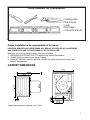
Tools needed for installation
Printed in U.S.A.. • Impreso en los Estados Unidos • Stampato negli Stati Uniti (revised 06/23/04)
22001460
• Cutting knife
• Nut drivers
• Level
• Duct tape
• Crescent wrench
Proper installation is the responsibility of the owner.
HOWEVER, SERVICE CALLS PERFORMED AS A RESULT OF POOR SET-UP, ADJUSTMENT
AND CONNECTION ARE THE RESPONSIBILITY OF THE INSTALLER.
Make sure you have everything necessary for proper installation.
1. GROUNDED ELECTRICAL OUTLET is required. See Electric Requirements.
2. POWER CORD for electric dryers (except Canada).
3. EXHAUST SYSTEM – must be rigid metal or flexible stiff walled metal exhaust ducting. See
Exhaust Requirements.
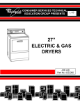
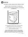
CABINET DIMENSIONS
24” / 60 cm
33.5” / 85 cm
24” / 60 cm
(Depth with dryer door open 90o - 38"
38.25”
/ 97 cm)
/ 97cm)
2
IMPORTANT TO INSTALLER
Please Read The Following Instructions Carefully Before Starting To Install The Dryer. These
Instructions Should Be Retained For Future Reference.
REMOVE THE DOOR FROM ALL DISCARDED APPLIANCES SUCH AS
DRYERS TO AVOID THE DANGER OF A CHILD SUFFOCATING.
LOCATION CONSIDERATIONS
The dryer should be located to permit adequate room in front for loading the dryer, and sufficient
room behind the dryer for the exhaust system.
This dryer is factory-ready for rear exhaust. To exhaust out the bottom or left side, use the accessory
exhaust kit (see Accessories). Instructions are included with the kit.
It is important to make sure the room has adequate make-up air. The area where the dryer is located
must not obstruct the flow of combustion or ventilating air.
THE DRYER MUST NOT BE INSTALLED OR STORED IN AN AREA WHERE IT WILL BE
EXPOSED TO WATER AND/OR WEATHER. THE DRYER AREA IS TO BE KEPT CLEAR AND
FREE FROM COMBUSTIBLE MATERIALS, GASOLINE AND OTHER FLAMMABLE VAPORS AND
LIQUIDS. A DRYER PRODUCES COMBUSTIBLE LINT. THE AREA AROUND THE DRYER
SHOULD BE KEPT FREE OF LINT.
ALCOVE OR CLOSET INSTALLATION
! WARNING WARNING –
The dryer must
be exhausted to
the outside to
reduce the risk
of fire when
installed in an alcove or closet.
•
An appliance installed in a closet shall have no
other fuel-burning appliance installed in the
same closet.
•
WARNING: To reduce the risk of fire, this
dryer MUST BE EXHAUSTED TO THE
OUTDOORS. See EXHAUST INFORMATION
section.
•
Minimum clearances between dryer cabinet and adjacent walls or other surfaces are:
0” either side 1” front and rear.
•
Minimum vertical space from floor to overhead cabinets, ceilings, etc. is 52”(132cm).
•
Closet door must be louvered or otherwise ventilated and must contain a minimum of
60 in2 (152.5 cm2) of open area equally distributed. If this closet contains both a
washer and a dryer, doors must contain a minimum of 120 in2 of open area equally
distributed.
3
MOBILE HOME INSTALLATION
The installation of the dryer in mobile homes must conform to the Manufactured Home
Construction and Safety Standard Title 24 CFR, Part 32-80 {formerly the Federal standard
for Mobile Home Construction and Safety, Title 24, HUD (Part 280), 1975} for the United
States,) or CSA Standards Z240 (for Canada). When installing a dryer in a mobile home,
provisions for anchoring the dryer to the floor must be made. An anchor bracket kit is
available with instructions (see Accessories). Locate in an area that has adequate make up
air. A minimum of 60 in2 (152.5 cm2) of unobstructed opening is required. All mobile home
installations must be exhausted to the outside with the exhaust duct termination securely
fastened to the mobile home structure, using materials that will not support combustion. The
exhaust duct may not terminate beneath the mobile home. See the section on exhausting for
more information.
EXHAUSTING
Exhausting the dryer to the outside will prevent large amounts of lint and moisture from being blown
into the room.
In the United States:
• Electric dryers located in a confined area such as a bedroom, bathroom, or closet must be
exhausted to the outside.
• Electric dryers not located in a confined area may be exhausted to the inside (see nonexhausted
installations.
In Canada:
• All dryers must be exhausted to the outside.
Outside the U.S. and Canada:
• Refer to local codes.
! WARNING
WARNING – plastic or nonmetal flexible duct presents a potential fire hazard.
NEVER USE PLASTIC OR NONMETAL FLEXIBLE DUCT.
If your existing ductwork is plastic, nonmetal or combustible, replace it with metal. Use only metal
exhaust duct that will not support combustion to insure the containment of exhaust air, heat and lint.
DUCTING REQUIREMENTS
•
•
•
•
•
•
Use A Minimum Of 4-inch (10.2 Cm) Diameter Rigid Aluminum Or Rigid Galvanized Steel
Duct.
Do not use smaller duct.
Ducts larger than 4 inches (10.2 cm) in diameter can result in increased lint accumulation. Lint
accumulation should be cleaned regularly.
If flexible metal duct must be used, use the type with a stiff sheet metal wall. Do not use
flexible duct with a thin foil wall. Serious blockage can result if flexible metal duct is bent too
sharp.
Never install any type of flexible duct in walls, ceilings or other concealed spaces.
Keep exhaust duct as straight and short as possible.
4
•
•
•
•
•
•
•
•
•
•
Secure joints with duct tape. Do not use screws.
DO NOT EXHAUST DRYER INTO ANY WALL, CEILING, CRAWL SPACE OR A
CONCEALED SPACE OF A BUILDING, GAS VENT, ANY OTHER COMMON DUCT OR
CHIMNEY. THIS COULD CREATE A FIRE HAZARD FROM LINT EXPELLED BY THE
DRYER.
Plastic flexible duct can kink, sag, be punctured, reduce airflow, extend drying times and affect
dryer operation.
Exhaust systems longer than recommended can extend drying times, affect machine
operation and may collect lint.
The exhaust duct should end with an exhaust hood with a swing out damper to
prevent back drafts and entry of wildlife. Never use an exhaust hood with a magnetic
damper.
The hood should have at least 12 inches (30.5 cm) of clearance between the bottom
of the hood and the ground or other obstruction. The hood opening should point down.
Never install a screen over the exhaust outlet.
When possible, do not exhaust the dryer directly into a window well in order to avoid
lint build-up. Do not exhaust under a house or porch.
If exhaust ductwork must run through an unheated area, the duct should be insulated
and slope slightly down towards the exhaust hood to reduce condensation and lint
build-up.
Inspect and clean the interior or the exhaust system at least once a year. Disconnect
electrical service prior to cleaning.
Frequently check to be sure the exhaust hood damper opens and closes freely.
If new dryer is installed into an existing exhaust system you must be sure:
•
•
•
•
•
The exhaust system meets all local, state and national codes.
That plastic flexible duct is not used.
Inspect and clean all lint accumulation from the interior of the existing duct.
The duct is not kinked or crushed.
The exhaust hood damper opens and closes freely.
5
The static pressure in any exhaust system must not exceed 0.48 inches of
water column, or be less than 0.
This can be measured with the dryer running with a manometer at the point where the
exhaust duct connects to the dryer. A no heat setting should be used. The dryer tumbler
should be empty and the lint filter clean.
NONEXHAUSTED INSTALLATIONS
•
•
•
If the electric dryer is not exhausted to the outside, the exhaust must not terminate
directly behind the dryer.
Use a rectangular vent kit along with a Dacron mesh lint bag (see Accessories).
Maintain a 6” (15.2 cm) clearance between the back of the control panel and the wall.
Although the lint screen and lint bag will retain most of the lint, a certain amount will be
expelled into the laundry area.
WARNING: IF THE DRYER IS NOT EXHAUSTED TO THE OUTSIDE, SOME FINE
LINT WILL BE EXPELLED INTO THE LAUNDRY AREA. AN ACCUMULATION OF
DUST OR LINT IN ANY AREA OF THE HOME CREATES A FIRE HAZARD. ANY
LINT ACCUMULATIONS MUST BE CLEANED FREQUENTLY.
ELECTRICAL REQUIREMENTS
NOTE: Wiring diagram is located inside the lower kick panel.
Export models (not U.S. or Canada): See Additional Instructions for Export Models on
last page of installation instructions.
! WARNING WARNING – To prevent unnecessary risk of fire, electrical shock or personal injury, all
wiring and grounding must be done in accordance with local codes, or in the
absence of local codes, with the National Electrical Code, ANSI/ NFPA (for the
United States) or the Canadian Electrical Code CSA C22.1 (for Canada).
GROUNDING
This dryer must be grounded. In the event of malfunction or breakdown, the ground will
reduce the risk of electrical shock by providing a path of least resistance for electrical current.
NEVER CONNECT GROUND WIRE TO PLASTIC PLUMBING LINES, GAS LINES OR HOT
WATER PIPES.
ELECTRIC MODELS
U.S. electric models are shipped with a ground strap connected from the neutral terminal
block post to the frame of the dryer. If local codes prohibit the use of the ground strap, the
dryer must be grounded in accordance with local codes.
6
If a power cord is not used and the electric dryer is to be permanently wired, the dryer must
be connected to a grounded metal, permanent wiring system; or an equipment-grounding
conductor must be run with the circuit conductors and connected to the equipment-grounding
terminal.
ELECTRICAL CONNECTIONS
BEFORE OPERATING OR TESTING, follow all grounding instructions in Grounding
Section. An individual branch (or separate) circuit serving only this appliance is
recommended.
DO NOT USE AN EXTENSION CORD.
ELECTRIC MODELS – U.S. Only
Most U.S. dryers, as manufactured, require a 120/240 volt, 60 Hz AC approved electrical
service. Some require 120/208 volt, 60 Hz approved electrical service. The electric service
requirements can be found on the data label located on the front behind the door. A 30ampere fuse or circuit breaker on both sides of the line is required.
! WARNING
• Improper connection of the equipment grounding conductor can result in a risk of electric
shock. Check with a qualified electrician or serviceman if you are in doubt as to whether
the appliance is properly grounded. Do not modify the plug provided with the appliance – if
it will not fit the outlet, have a proper outlet installed by a qualified electrician.
• To prevent unnecessary risk of fire, electrical shock or personal injury, all wiring
and grounding must be done in accordance with local codes, or in the absence of local
codes, with the National Electrical Code, ANSI/ NFPA No. 70-Latest Revision (for the US)
or the Canadian Electrical Code CSA C22.1 - Latest Revisions and local codes and ordinances. It is the
personal responsibility and obligation of the appliance owner to provide adequate electrical services for
this appliance
• All gas installations must be done in accordance with the national Fuel Code ANSI/Z2231 - Last revision
(for United States) or CAN/CGA - B149 Installation Codes - Latest Revision (for Canada) and local codes
and ordinances.
•
A 120/240-volt U.S. electric dryer must be converted if it is to operate on a 120/208 volt
electrical system.
•
If a power cord is used, the cord should be plugged into a 30-ampere receptacle.
•
The power cord is NOT provided with U.S. electric model dryers.
IMPORTANT: When permitted by local codes, the dryer electrical supply may be connected by
means of a new power supply cord kit, marked for use with clothes dryer, that is U.L. listed, rated at
120/240 volts minimum, 30 amperes with three No. 10 copper wire conductors terminated with closed
loop terminals, open-end spade lugs with turned up ends or with tinned leads.
•
Do not reuse a power supply cord from an old dryer. The power cord electric supply wiring
must be retained at the dryer cabinet with a suitable UL listed strain relief.
7
•
If the dryer is to be installed in a mobile home or an area where local codes do not permit
grounding through neutral, only a 4 conductor power cord, rated and terminated as above,
may be used.
ELECTRIC MODELS – Canada Only
•
A 120/240 volt, 60 Hz AC approved electrical service fused through a 30 ampere fuse or
circuit breaker on both sides of the line is required.
•
All Canadian models are shipped with the power cord attached. The power cord should be
plugged into a 30 ampere receptacle.
NOTE: It is not permissible to convert a dryer in Canada to 208 volts.
REPLACEMENT PARTS AND ACCESSORIES
If your dryer requires replacement parts or accessories, contact the dealer from whom you
purchased your dryer or Maytag Customer Service, Box 2370, Cleveland, Tennessee 373202370, phone 423-472-3333, for information on the nearest authorized Maytag Parts
Distributor.
8
INSTALLATION
Parts and literature are packaged inside of dryer drum.
To Install…
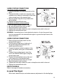
1. Move dryer to an appropriate location for installation. Consider installing the dryer before the
washer in side-by-side installations, to allow access to gas, electrical and exhaust connections.
Lay two of the carton corner posts on the floor. Tip the dryer forward on its front so it will lay
across both corner posts.
2. Set the dryer back in an upright position.
3. Review the Exhausting Section before installing the exhaust system. Install the ductwork from the
dryer to the exhaust hood. The crimped end of the duct sections must point away from the dryer.
DO NOT use sheet metal screws when assembling ducting. These joints should be taped. Never
use plastic flexible exhaust material.
Tip for tight installations: install a section of exhaust system to the dryer before moving the dryer
in place. Use duct tape to secure this section to the dryer but do not cover louvers in dryer
cabinet.
4. Review Electrical Requirements Section.
BEFORE OPERATING OR TESTING, follow the grounding instructions in the Grounding Section.
U.S. MODELS:
IMPORTANT – All U.S. models are produced for a 3-WIRE SYSTEM CONNECTION. The dryer
frame is grounded to the neutral conductor at the terminal block.
A 4-WIRE SYSTEM CONNECTION is required for new or remodeled construction, mobile homes,
or if local codes do not permit grounding through neutral. If the 4-wire system is used, the dryer
frame cannot be grounded to the neutral conductor at the terminal block. Refer to the following
instructions for 3- and 4-WIRE SYSTEM CONNECTIONS.
Remove the terminal block cover plate.
Insert the power cord with a U.L. listed strain relief
through the hole provided in the cabinet near the terminal
block. NOTE: a strain relief must be used.
Do not loosen the nuts already installed on the terminal
block. Be sure they are tight. Use a 3/8” (1 cm) deep well socket.
9
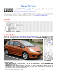
3-WIRE SYSTEM CONNECTIONS
If the power cord has ring terminals:
1. Place the terminals over the existing nuts on the
posts.
2. The neutral (white or center wire on power cord)
conductor must always be connected to the center
(silver colored) post of the terminal block.
3. Secure in place using the nuts provided in the
parts package.
4. Replace the terminal block cover.
If the power cord does not have terminals:
1. Use the cupped washers ahead of the nuts.
2. Be sure the terminal block nuts are tight.
3. Secure the power cord in position.
4. Tighten the strain relief screw(s) in order to clamp the strain relief to the cord.
5. Replace the terminal block cover.
WARNING: If converting from a 4-wire electrical system to a 3-wire, the ground strap
must be reconnected to the terminal block support to ground the dryer frame to the
neutral conductor.
4-WIRE SYSTEM CONNECTIONS
1. Remove the ground strap screw from the
terminal block support.
2. Fold the ground strap over so both ends of
the ground strap will be attached to the
center terminal block post.
3. Connect the neutral (white) conductor of the
cord to the center (silver) post of the terminal
block.
4. Connect the grounding (green) wire of the
cord to the terminal block support using the
ground strap screw.
5. Connect the red and black wires of the cord
to the outer posts of the terminal block.
6. Be sure the terminal block nuts are on tight.
7. Secure the power cord in position.
8. Tighten the strain relief screw(s) in order to clamp the strain relief to the cord.
9. Replace the terminal block cover.
EXPORT MODELS
Refer to last page of installation instructions.
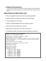
6. Level The Dryer:
With a level, check the dryer, and make necessary adjustments to the leveling legs.
10
7. Check All Connections:
At this time, make sure all gas connections (on gas models), exhaust and electrical
connections are complete. Plug dryer in, and check operation by using the check list
below.
FINAL INSTALLATION CHECK LIST
q Dryer is plugged into electrical outlet and is properly grounded.
❏
q Exhaust ductwork is hooked up to dryer and all joints taped.
❏
q Plastic flexible duct is NOT used.
❏
q Rigid or stiff walled flexible metal vent material was used.
❏
q Dryer is level with all legs firmly on the floor.
❏
q Start dryer to confirm dryer runs, heats and shuts off.
❏
❏
q Provide User Guide to consumer and demonstrate dryer operation.
HOUSEHOLD INSTALLATION ACCESSORIES
• Vent hood – 4” (10.16 cm) opening – 059129
• Aluminum pipe – 4” x 24” (10.16 cm x 60.96 cm) – 059130
• Aluminum elbow – 4” (10.16 cm) – 059131
• Aluminum window plate – 15” x 20” (38.10 cm x 50.80 cm) – 4” (10.16 cm) hole – 059134
• Flexible aluminum vent duct – 4” (10.16 cm) diameter – 38” (81.28 cm) length stretches to
8’ (2.44 cm) – 304353
• Clamp for flexible aluminum duct – 304630
• Exhaust duct kit for base or left side exhausting – 12001453
• Rectangular vent kit – 059144
• Dacron lint bag – 311353
• Anchor bracket kit – 303740
• Grounding kit – 12001875
• Power cords – 240 v, 30 A
4’ (121.9 cm) – 3-wire – 33001780
5’ (152.4 cm) – 3-wire – 33001822
6’ (182.9 cm) – 3-wire – 33001823
10’ (304.8 cm) – 3-wire – 33001838
4’ (121.9 cm) – 4-wire – 33001781
5’ (152.4 cm) – 4-wire – 33001824
6’ (182.9 cm) – 4-wire – 33001825
10’ (304.8 cm) – 4-wire – 33001838
11
ADDITIONAL INSTRUCTIONS FOR EXPORT MODELS
(Not U.S. or Canada) Contact the distributor that sold the appliance or: Maytag
International, 8700 W. Bryn Mawr Avenue, Chicago, Illinois USA 60631, 773-714-0100, for
information on product, shipping damage, replacement parts and accessories.
Maytag dryer models manufactured for operation on 60 Hz AC are not designed for use on
50 Hz AC electrical service and conversion of the product from 60 to 50 Hz operation is not
recommended. For additional information on 50 Hz products, contact Maytag International.
The electric service requirements can be found on the data label located on the front of the
dryer behind the door.
EXPORT ELECTRIC MODELS
Export electric models are manufactured for operation on either 230/240 volt, 50 Hz or 220
volt, 60 Hz approved electric service. A two-wire approved electrical service with a 30ampere fuse or circuit breaker is required. The dryer must be properly grounded with a
ground wire.
IMPORTANT: When permitted by local codes, the dryer electrical supply may be connected
by means of a new power supply cord kit, marked for use with clothes dryers, that is agency
listed, rated at 240 volts minimum, 30 amperes with two No. 10 copper wire conductors
terminated with closed loop terminals, open-end spade lugs with turned up ends or with
tinned leads. Do not reuse a power supply cord from an old dryer. The power cord or electric
supply wiring must be retained at the dryer cabinet with a suitable agency listed strain relief.
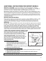
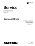
2-WIRE AND GROUND SYSTEM CONNECTIONS
Remove the terminal block cover plate. Insert the power cord
with an agency listed strain relief through the hole
2-Wire and Ground System
provided in the cabinet near the terminal block. Note, a
strain relief must be used. Do not loosen the nuts
Power
Neutral
already installed on the terminal block. Be sure they are
Cord
Post
Ground
tight. Use a 3/8” (1 cm) deep well socket. Secure the
Wire
power cord ground wire to the terminal block support
using the ground screw.
Power
If the power cord has ring terminals:
cord
1. Place the terminals over the existing nuts on the
Neutral
and
posts. The neutral wire in power cord must be
strain
relief
connected to the center (silver colored) post of the
terminal block.
2. Secure in place using the nuts provided in the parts package.
3. Replace the terminal block cover.
If the power cord does not have ring terminals:
1. Use the cupped washers ahead of the nuts. Be sure the terminal block nuts are tight.
2. Secure the power cord in position.
3. Tighten the strain relief screw(s) in order to clamp the strain relief to the cord.
4. Replace the terminal block cover.
BEFORE OPERATING OR TESTING, be sure the machine is properly grounded.
12