1
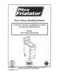
$15.00
OPERATION & MAINTENANCE
MANUAL
IMPORTANT: CAUTION! TO REDUCE RISK OR
INJURY, READ OPERATING INSTRUCTIONS
CAREFULLY BEFORE USING
CP SERIES
HD SERIES
SC SERIES
SS SERIES
© Hydro Tek 1/2007
XBTIJOH!BDDFTTPSJFT
HYDRO TWISTER
®
The ANT3C Contractor Series HYDRO
TWISTERS are the proven choice for
professional surface cleaning with three
options for your cleaning needs. The
ANT3C is a 3-in-1 rotary surface cleaner
and includes a spot / gum remover and a
hydro broom creating an all-in-one portable
system. The dual trigger gun control allows
you to activate either device simply by pulling
the appropriate trigger. By combining three
processes into one unit, you will save time
and fatigue when cleaning large expanses of
concrete, parking lots or other flat surfaces.
The secret that makes the Contractor Hydro
Twister so effective is the water spray angles
and nozzle heights optimizing the unit for
maximum cleaning power.
Use the water broom function to power away
debris and dirt in a 28” wide swath and the
job is done.
Advantages…
One
unit
• Multipurpose:
includes a gum & spot
remover, water broom and
a rotary cleaner to get jobs
done faster.
• Stainless Steel Construction:
Heavy Duty, lifetime corrosion
resistance.
• High Productivity: Cleans
up to 15 times faster than
an operator with a handheld
wand.
SURFACE CLEANERS
The ANT38 HYDRO TWISTER is a unique surface
cleaner with a 38” cleaning path. The impressive size and
construction allows the operator to maneuver and clean
wide areas in one pass. Suitable for use on greasy factory
floors, concrete parking lots and drive thru areas, gas
stations and garages.
Advantages...
• Stainless steel construction for lifetime corrosion
resistance. Saves time, money and fatigue.
Specifications...
Up to 4000 PSI
Up to 5 - 7 GPM
38” Cleaning Path
Temperatures up to 200° F
The Hydro Twister ANT20 and ANT28 are surface
cleaners that connect to a pressure washer and uses
two nozzles rotating at a high RPM within 1” of the
ground. It will clean concrete at up to 15 times the speed
of an operator using a wand and with more consistency
and less operator fatigue. Simply move the
twister over the surface and watch a clean
path appear behind the unit.
Advantages...
• Three Stainless Steel Sealed Bearings:
Requires no maintenance
• Carbide Seal Design: Offers long life at
high temperatures
• All Stainless Steel Construction: Provides
lifetime corrosion resistance.
Integrated water broom and spot remover
ANT20 has lightweight
Specifications...
composite deck
Up to 4000 PSI
Up to 10 GPM (5 GPM Standard)
20” or 28” Cleaning Path
Temperatures up to 250° F
Specifications...
Up to 4000 PSI
28” Cleaning Path
Up to 10 GPM (5 GPM Standard)
Temperatures up to 250° F
WASH WATER RECYCLE / RECOVERY / FILTRATION
IZESP ! MPPQ
WASH - CONTAIN - RECYCLE
TRAILERS
200 - 500 Gallon
TANK SKIDS
OTHER ACCESSORIES
HOSE EXTENTIONS
Bmm!sjhiut!sftfswfe!!3118/!Tqfdjgjdbujpot!nbz!wbsz
ADJUSTABLE
PRESSURE WAND
HOSE REELS
TURBO
NOZZLE
SAND
BLASTER
CHEMICAL
INJECTORS
TABLE OF CONTENTS
3
INTRODUCTION ............................................................................................................................... 4
Statement of Warranty
SAFETY WARNINGS ....................................................................................................................... 5
Electrical Precautions
Fire Precautions
Ventilation Precautions
Spray Injection Precautions
Personal Hazard Precautions
OPERATING INSTRUCTIONS ....................................................................................................... 6
Before Start Up
Operation
Shut Down & Antifreeze Protection
SYSTEM INFORMATION ................................................................................................................. 7
Power System
Electric Motor/Gasoline Engine
Power Transmission System - direct & belt drive
Generator - circuit breaker
Pumping System ........................................................................................................................ 8
Pump
Unloader, Pressure Relief Valve and Burst Disk
Chemical Injection System - inlet & downstream injection
Water Supply - direct, float tank, & supply tank feed
Heating System .......................................................................................................................... 9
Coil/Heat Exchanger System - temperature & flow switch controls
Diesel Fired Burner - air band, transformer, fuel pump, filter, & solenoid
Pressure Delivery System ......................................................................................................... 10
Discharge Hose, Hose Reels
Gun/Wand Assembly - trigger gun, wand, & quick coupler
Nozzles - spray nozzles, steam nozzle and turbo nozzle
Hydro Twister
TRAILERS........................................................................................................................................... 11
TROUBLE SHOOTING GUIDE ....................................................................................................... 12-15
WIRING DIAGRAMS ......................................................................................................................... 16-22
SERVICE RECORD.............................................................................................................................23
SERVICE/MAINTENANCE INFORMATION ................................................................................ 24
TEST SPECIFICATIONS .............................................................................................................. Enclosed
ENGINE SHEET ............................................................................................................................ Enclosed
PARTS LIST / EXPLODED VIEW ................................................................................................ Enclosed
INSTALLATION INSTRUCTIONS ............................................................................................. Enclosed
USE ONLY HYDRO TEK CERTIFIED ORIGINAL EQUIPMENT
REPLACEMENT PARTS, FAILURE TO DO SO COULD LEAD TO
WARRANTY EXCLUSION AND SEVERE BODILY INJURY
4
INTRODUCTION:
THANK YOU: The employees and management of
HYDRO TEK SYSTEMS, INC. thank you for selecting our
products. The production and quality assurance personnel have
taken the greatest care in the assembly process to ensure that your
new Industrial Cleaning Equipment exceeds the standards set by
you, the customer, by Hydro Tek engineering and management, and
by our safety certification to U.L. 1776.
YOUR RESPONSIBILITY: This operator’s manual was compiled
for your benefit. By studying and following the safety, installation,
operation, maintenance, and troubleshooting information contained
within, you can look forward to many years of trouble free service
from your equipment. Every person who will operate the
equipment must read and follow the safety warning and operating
instruction sections of this owner’s manual prior to use. You are
responsible for operating the product properly and safely. You are
also responsible to follow the maintenance schedule on the back page
of this manual to keep your warranty active.
FREIGHT DAMAGE: If delivered by trucking company, please
inspect for any concealed freight damage and note this on the
paperwork from the trucking company before signing. Should you
find damage has occurred during shipping, do not return the damaged
merchandise to Hydro Tek, but file a claim immediately with the
freight carrier involved.
QUESTIONS: Help us provide you with the fastest service. Please
locate the enclosed warranty registration card and return it to Hydro
Tek to register your machine. Contact your local AUTHORIZED
HYDRO TEK SERVICE DEALER that you purchased from or call
HYDRO TEK factory and ask for technical services if problems
occur. THERE ARE NO USER SERVICEABLE COMPONENTS
ON THIS EQUIPMENT.
GETTING STARTED: If your dealer has not prepared the machine
for startup, you may need to connect the hose to the pressure outlet
on the washer and connect the other end of the hose that swivels to
the trigger gun inlet and tighten. The water will be removed or antifreeze solution will be added to the pump and coil. Mobile Wash
Skids are engine powered and shipped from the factory with the fuel
tanks empty, the battery cables disconnected, the battery dry (if
included on engine powered units). Fill the battery to the fill line
with electrolyte (available at a local auto parts store), connect the
battery cables, and follow the operation instructions for starting.
Pressure Steamers are electric powered and will require an
appropriate electric outlet or disconnect box and an electric plug that
is rated for your machine’s voltage and amperage and matches to
your electrical socket. Smaller machines are equipped with a ground
fault interrupter on the electrical cord and you will need to press the
reset button after it is plugged in. (See Operating Instructions
section and enclosed page on Installation Guidelines).
NO NONSENSE GUARANTEE:
Hydro Tek Systems, Inc. (Hydro Tek) promises to repair Ultimate
and Proline washers if defective in materials or workmanship for one
year from the date of original retail purchase including the costs of
PARTS and LABOR, but you must pay transportation costs and
travel time.
Items and Conditions Not Covered:
1.Normal wear items such as discharge hose, guns, wands, spray
arms, nozzles, quick couplers, o-ring, pump packing, brushes,
filters, belts, and tires.
2.Cost of regular maintenance or adjustments or damage from lack of
maintenance.
3.Damage due to freezing, abrasive fluids, chemical deterioration, and
scale build up.
4.Damage from fluctuation in electrical or water supply.
INTRODUCTION
5.Any product or part which has been altered, modified, over
pressurized, misused, or been in an accident.
6.Dealer installation or damage from improper installation of the
machine or alteration by a dealer or promise of additional warranty
from dealer. The factory warranty is not transferable from the dealer
to the retail purchaser on used or rented equipment.
7.Labor is not paid if the dealer that serviced your machine is not an
authorized service center.
8.Labor is not paid on added accessories such as surface cleaners,
hose reels, wastewater recycler, and vacuums.
WARRANTY PROVIDED BY OTHERS: Gasoline, diesel engines
and some electric motors are warranted by the manufacturer of the
motor and their warranty is provided through the manufacturer's
service centers.
BIG 6 COIL REPLACEMENT: Should the heater coil leak under
normal conditions within the first 6 years of service, Hydro Tek will
provide a replacement coil free of charge. Failure from freezing or
freight and installation labor excluded.
GENERALCONDITIONS:
Hydro Tek's responsibility with respect to claims is limited to
making the required repairs or replacements to the original retail
user, and no claim of breach of warranty shall be cause for any
cancellation or rescission of the contract of sale of any Hydro Tek
product. Hydro Tek reserves the right to change or improve the
design of any of its products or illustrations without assuming any
obligation to modify any product previously manufactured.
This supersedes any and all previous warranty statements
for products purchased after January 1, 2007. Hydro Tek is not
liable for indirect, incidental or consequential damages including any
cost of substitute equipment, loss of revenue, pecuniary expense or
loss, or any damages whatsoever arising out of the use or inability to
use a Hydro Tek product. Hydro Tek disclaims all implied
warranties, including those of merchantability and fitness for use for
a particular purpose. Some states do not allow exclusions or
limitations on how long an implied warranty lasts, so the above
exclusions may not apply to you. It is the buyer's responsibility to
ensure installation and use of Hydro Tek products conforms to local
codes. Products exported outside the US and Canada are covered
solely by the warranty of the local export dealer and this warranty
does not apply.
HOW TO OBTAIN WARRANTY SERVICE:
1.Write down your model #_________________and serial
#________________(on base plate of machine near the motor).
2.Contact your local service dealer and return the Hydro Tek washer
or part within the warranty period along with your sales receipt. To
locate service, call the factory and ask for technical services or go to
www.hydrotek.us
3.You may also ship the defective part freight prepaid directly to
the factory if you contact technical services first and we will issue
you a return goods authorization and then repair or replace under the
conditions of warranty. We will pay the cost of returning it back to
you by a method of our choice.
4.If the defective component is an engine or motor made by another
manufacturer, your authorized Hydro Tek dealer or we can help you
obtain warranty service through the specific manufacturer’s local
authorized service center.
5.If you are unable to resolve the warranty claim, write to Hydro
Tek Systems, Inc., 2353 Almond Ave, Redlands, CA 92374. Attn:
Technical Services. Please enclose a copy of the dated purchase
receipt and explain the nature of the defect.
IMPORTANT SAFETYWARNINGS:SAVETHESE INSTRUCTIONS
3.
4.
ELECTRICAL PRECAUTIONS:
1. Observe all State, Local, and National codes for the installation of your electrically powered washer.
2. For a grounded product rated 250 volts, single phase, or less:
This Product Is Provided With A Ground Fault Circuit
Interrupter Built Into The Power Cord Plug. If Replacement
Of The Plug Or Cord Is Needed, Use Only Identical Replacement Parts.
3. GROUNDING INSTRUCTIONS:
Cord Connected, Grounded Products:
This product must be grounded. If it should malfunction or
breakdown, grounding provides a path of least resistance for
electric current to reduce the risk of electric shock. This product
is equipped with a cord having an equipment-grounding conductor. The plug must be plugged into an appropriate outlet that
is properly installed and grounded in accordance with all local
codes and ordinances.
Danger - Improper connection of the equipment-grounding
conductor can result in a risk of electrocution. Check with a
qualified electrician or service personnel if you are in doubt
as to whether the outlet is properly grounded. Do not modify
the plug provided with the product, do not cut off the ground
pin - if it will not fit the outlet, have a proper outlet installed
by a qualified electrician. Do not use any type of adaptor with
this product.
4. To comply with the national electric code, this pressure
washer should only be connected to a receptacle that is
protected by a ground fault circuit interrupter (GFCI).
5. EXTENSION CORDS:
Use of extension cords is not recommended.
6. NEVER operate an electrically powered washer after it has
tripped a breaker or a ground fault device without having the
reason for the trip determined by an authorized service
engineer or competent electrician.
7. Use only in a dry area. Do not handle electrical cords and
plugs when they are wet, when your hands are wet, or when
standing in water. Do not spray high pressure water on to
the machine.
8. Disconnect power supply before making any repairs or adjustments.
9. Transformer on burner is 20,000 volts. Disconnect battery
cable before servicing burner or engine on 12 volt systems.
WARNING: FIRE EXPLOSION HAZARD CAN CAUSE
SEVERE INJURY OR DEATH AND PROPERTY DAMAGE!
FIRE PRECAUTIONS:
1. DO NOT use improper fuels or solvents in this equipment, and only
fill with the correct fluids when the unit is in an OFF condition, main
power is disconnected, and engine and burner are cool.
2. Fill the diesel burner fuel tank with #2 diesel fuel or kerosene. NEVER
5.
6.
7.
8.
9.
5
use gasoline. Do not confuse gasoline and fuel oil tanks. Keep proper
fuel in proper tank.
NEVER operate this equipment in the presence of flammable vapors,
dust, gases, or other potentially combustible materials.
AVOID contact with the exterior of the coil/heat exchanger assembly,
exhaust stack and mufflers to prevent burns.
DO NOT store fuel or other flammable materials near the burner or
any other open flame.
To avoid burns NEVER stand over burner exhaust outlet or in front of
engine exhaust. Burner may start at any time once power is turned on.
Do not touch burner exhaust port, mufflers, or wands/hoses as
contact may cause burns. Use designated gripping areas.
Diesel fired or gasoline powered units are designed for outdoor
use and installation only.
Burner on/off switch must be placed in the OFF position when
the pressure washer is not being used. Do not depend on engine
run switch to turn the burner off - This may cause a safety hazard.
VENTILATION PRECAUTIONS:
1. DO NOT run engine or burner in an enclosed area. Exhaust gases
contain carbon monoxide, an odorless deadly poison.
2. Observe all State, Local, and National codes providing for
indoor use or installation of this unit.
3. Provide adequate ventilation to prevent engine overheating
and inefficient burner combustion
(minimum 2' of air space).
SPRAY INJECTION PRECAUTION:
1. Fluid from high pressure spray or leaks can penetrate the skin and
cause serious injury. If any fluid appears to penetrate the skin get
emergency medical help at once. DO NOT treat as a simple cut.
Tell the physician exactly what fluid was injected. For treatment
instructions have the physician call your local poison center.
Without proper treatment, complications can develop.
2. WARNING - Risk of injection or severe injury to persons - Keep
clear of nozzle. DO NOT direct discharge stream at persons. This
machine is to be used by trained operators. Keep operating area
clear of all persons.
CAUTION: Hot discharge fluid - DO NOT touch or direct
discharge stream at persons. Gun kicks back - Hold with both
hands. Stay alert - Watch what you are doing.
3. Always wear protective eye goggles when operating the
equipment. Additional protective items such as a rubber suit
and boots, gloves, and respirators are advisable, particularly
when using cleaning detergents with a corrosive content.
4. Know the detergents you are using. Read and follow the
directions on the detergent labels.
PERSONAL HAZARD:
1. DO NOT remove belt guards or electrical covers while engine is
operating or when the power is connected.
2. DO NOT move engine powered machinery while the engine
is operating.
2. DO NOT lock the trigger on the gun valve in the on position.
3. DO NOT exceed recommended operating pressure or temperature.
4. KEEP HANDS CLEAR OF BELTS AND MOVING PARTS.
5. Do not operate the product when fatigued or under the
influence of alcohol or drugs.
6
BEFORE START UP:
1. Read all instructions before using this product.
2. CHECK OIL AND FLUID LEVELS:
Check pump oil by locating the oil view window or
dipstick and fill to the red dot. Check fuel
levels. Check engine oil and coolant
levels if unit is so equipped.
(See the maintenance schedule on page 16).
3. CONNECT HOSE AND GUN ASSEMBLY: The hose
has a swivel on one end. Connect swivel end to gun after
wrapping end with tape thread sealer.
4. CONNECT THE WATER SUPPLY & TURN WATER ON:
Maintain an adequate supply of
water using a ¾" I.D. hose with a
pressure between 25 and 60 PSI.
Burner power switches should be
off before starting. If tank fed, be sure there is water in
the tank and the valve is switched for supply tank feed.
Do not run dry for longer than one minute. Note: CP and
most HG Series machines will not start if water is off.
5. BATTERY INFORMATION:
If you did not order a battery with
your machine you will have to buy
one and fill it with electrolyte
EB24F
(available at local auto parts store).
!WEAR EYE PROTECTION!
If the opening on your battery box
measures 9" by 6" we recommend Exides' U1L/GTH
235CCA battery. If the opening measures 8" by 12" we
recommend Exides' group 46-60 550 CCA battery. Deep
cycle batteries are recommended to extend battery life.
Always connect the positive battery cable before the
negative and coat the battery terminals with corrosion
inhibitor to prevent corrosion.
6. If wheel kit, accessories, or discharge hose are not
installed, see your local dealer for installation instructions.
OPERATION:
1. STARTING:
A. Electric Powered Units: Connect power supply and
ensure that all wiring connections and voltages are of
sufficient rating to comply with the equipment's requirements. Turn pump power switch on. If unit is equipped
with auto-start, keep all power switches off when left
unattended. (Unit will only turn on when trigger gun is
pulled).
B. Gasoline Engine Units: To reduce the risk of starter
damage remove spray nozzle from wand and pull spray gun
trigger while cranking engine. After start, release trigger and
replace spray nozzle. Be sure nozzle is properly positioned
in quick disconnect before spraying.
OPERATING INSTRUCTIONS
2. PURGE AIR FROM SYSTEM: Squeeze the trigger on the
spray gun until a constant stream of water comes out. (Purging
works best with nozzle removed from wand and/or dual wand
in the low pressure mode.)
3. SELECT DESIRED NOZZLE:
Lock collar
after nozzle
is inserted
Connect nozzle securely to spray wand. If equipped,
close pressure adjusting knob on dual wand. Hold gun
firmly, squeeze trigger for high pressure spray. O-ring
should be replaced with 1/4" or 3/8" EPDM.
CAUTION - Gun kicks back - hold with both hands.
WARNING - Risk of explosion DO NOT spray flammable liquids.
4. START BURNER: To create hot water on high pressure
washers equipped with heat exchangers, release the trigger
on the gun, turn the burner to the
on position, and turn the thermoPUMP &
stat to the desired temperature. BURNER
Squeeze the trigger on the POWER
CHEM.
spray gun and the burner will
TEMP CONTROL
begin heating the water. It will
INJ.
stop firing whenever the water
spray is off or if the temperature setting is exceeded.
5. STEAM: (If Equipped)Insert steam nozzle and turn thermostat to 250º steam setting. The steam nozzle is sized
for approximately 25% less water volume than the hot
water mode.
Warning: Cool down burner before shutting off.
6. BYPASS MODE: System will go into bypass mode when
machine is left running and trigger gun is closed. Bypass
mode is when the inlet water coming into the pump
recirculates through the unloader across the pump head.
If left in bypass too long - More Than Five Minutes friction created by the movement of the water will begin
to heat the water at a rapid rate. If equipped with a
THERMAL DUMP VALVE, water exceeding 145° F
will cause the valve to open allowing the hot water out of
the system into the atmosphere and allow cool water in.
The valve will reset itself when water temperature
comes down to a safe level. If equipped with a bulk water
tank, water can be bypassed back through the tank allowing
for a larger volume of water to be recirculated through the
pump head thus reducing heat on the pump seals. If equipped
with By-pass-cool system, a small portion of the bypass
water is routed back through the float tank to keep the pump
cool.
!Warning: Do not leave in bypass for longer than five
minutes to prevent pump from overheating.
SHUT DOWN / SYSTEM INFORMATION
7. SET CHEMICAL INJECTION: If unit is equipped with inlet
chemical injection, place chemical pickup tube in pre-mixed
chemical solution and open chemical valve for desired chemical concentration. Rinse and close valve after use, do not use
harsh chemicals through the inlet injector system. If unit is
equipped with a downstream chemical injector, connect the
chemical injection assembly into the high pressure discharge
hose quick connects. Place the chemical pickup into chemical
solution and turn brass collar to adjust concentration. The
chemical will inject only when you drop the outlet pressure by
opening the valve on the dual wand or changing to a low
pressure nozzle. Soap the surface from the bottom up. Close
chemical valve when not in use.
MAINTAIN PH BETWEEN 5 & 9
8. If equipped, AF2 (2) gun operation, select "50%"
nozzle from panel and insert into coupler on spray
gun for full pressure output when using two guns at
the same time. Flow can be reduced by selecting flow
reduction nozzles only when one operator is using the
machine. Maximum temperature is 200° F.
SHUT DOWN:
1. TURN BURNER SWITCH TO THE OFF POSITION.
2. RINSE & CLOSE CHEMICAL VALVE.
3. SQUEEZE THE TRIGGER ON THE SPRAY GUN
UNTIL THE WATER BECOMES COOL.
4. TURN MOTOR/ENGINE SWITCH OFF with the
appropriate controls.
5. TURN OFF WATER SUPPLY.
6. SQUEEZE TRIGGER TO RELEASE ANY
TRAPPED PRESSURE IN DISCHARGE HOSE.
7. ANTIFREEZE EQUIPMENT:
In the event that the equipment is not to be used for an
extended period, store in heated space or antifreeze the unit.
Run the machine until the float tank is near empty, fill with
a 50% mix of water and antifreeze and run until antifreeze
appears at the high pressure outlet. If unit is equipped with
a blow out valve, it may be blown out with compressed air
in addition to using antifreeze solution. On direct feed units
(no float tank), use a 5' garden hose to draw the antifreeze
mix from a bucket. Or blow out the unit with compressed
air until only air and no water comes out of the discharge.
7
Be sure that the trailer you order conforms to your particular
State Department of Transportation regulations in effect at
this time, including braking and lighting requirements. If
water is being transported on the highway, trailer brakes are
recommended.
To insure safe trailering, be certain that the hitch on
your tow vehicle is rated for the full trailer weight and of the
proper height so that the trailer remains level when hitched,
or wheel damage could result. DOUBLE CHECK safety
chain, hitch coupler and wire harness before departing.
Check latch on coupler and adjust, if required, to fit your
trailer ball properly.
POWER SYSTEMS:
ELECTRIC MOTORS: All single phase
electric motors contain a manual or automatic thermal overload which will shut down
the motor if it overheats. If the overload or
starter shuts down the motor, have an electrician or an authorized Hydro Tek distributor check for electrical
problems. Voltage reading under load should be +/- 10% of
name plate voltage on motor. The motor can be reset by
depressing the red overload button located on either the
motor or the starter, (as shown above). Use thumb pressure
only - DO NOT force. Wait for motor to cool before
resetting. The automatic overload will reset itself after the
motor has cooled. Never spray water on the unit, or damage
to the electric motor(s) may occur. Consult the factory if
running an electric machine from a generator. Three times
total system wattage is required.
A=TOTAL SYSTEM AMPERES
HORSE 115V WIRE 208V WIRE 208V WIRE 230V WIRE 230V WIRE 460V
POWER 1PH SIZE 1PH SIZE 3PH SIZE 1PH SIZE 3PH SIZE 3PH
1.5
2
5
6.5 / 6
7.5
10
15
15A
20A
N/A
N/A
N/A
N/A
N/A
12/3
12/3
N/A
N/A
N/A
N/A
N/A
N/A
N/A
26A
N/A
N/A
50A
N/A
N/A
N/A
10/3
N/A
N/A
#8
N/A
N/A
N/A
N/A
N/A
N/A
32A
40A
N/A
N/A
N/A
N/A
N/A
#8
#8
10A
12A
24A
27A
35A
48A
N/A
14
14
10/3
10/3
#8
#8
N/A
N/A
N/A
N/A
22A
N/A
30A
38A
N/A
N/A
N/A
12/4
N/A
#10
#8
N/A
N/A
N/A
13A
N/A
16A
20A
WIRE
SIZE
N/A
N/A
N/A
14/4
N/A
#12
#12
A fused disconnect switch of sufficient ampere rating
should be installed by an electrician to provide power to the
machine. Refer to the chart above for electrical requirements: (208 Volt is acceptable, but unit motor must be under
nameplate amps; turn psi down). If your unit is equipped with
a ground fault interrupter, it will have to be reset whenever it
CHASSIS & TRAILER ASSEMBLY:
is plugged in, or if a ground fault interruption occurs. Test
To maintain the appearance of the machine use stainless regularly for proper operation.
steel cleaner on the stainless steel panels.
GASOLINE ENGINE: With the proper care and mainCheck tire air pressure. Check all bolts including the
tenance, your gasoline engine will give years of trouble free
lug nuts for tightness and condition periodically. Grease service. Please follow the Service and Maintenance Guide
and the enclosed engine sheet or contact your local authorized
wheel bearings as required and adjust after first month.
engine dealer for maintenance and repairs.
TIRE PRESSURE
Use unleaded gasoline with an octane rating of 87 or
T3000 T3500 T4500 T5500
higher
in the engine fuel tank. Consult engine manual for
35 psi 35 psi 40 psi 45 psi
proper oil type and capacity. Change oil every 50 hours and
the filter every 100 hours (see engine manual).
8
Do not rely on the low oil shutdown (if equipped) as a
reminder to add oil. Engine damage from lack of oil will
typically not be warranted even if the low oil system failed.
On machines with a 115V generator or a 12V burner, the
throttle is preset at the factory (See Generator section on this
page for adjustment).
POWER TRANSMISSION:
DIRECT DRIVE: Pump is bolted directly to the motor/
engine. If pump needs to be removed, do not force off by prying
or damage may occur. When reassembling, coat the entire
motor shaft with heavy grease, or a generous amount of antiseize and use service removable "lock tight" on mounting bolts.
BELT DRIVE: Check belt condition, alignment and tension
periodically. Replace belts when they show signs of wear or
cracking. Tighten belts by loosening the mounting bolts on the
pump and generator to permit them to slide. Turn the horizontal
rail adjusting bolts to tighten belts until they deflect ¼" to ½" inch
with finger pressure.
GENERATOR:
Some self-contained Hot Water Units
are equipped with a 115 volt generator to
power the diesel burner. The generator
output voltage must be between 110 to
130 Volts, (or between 59 to 63hz), when
the unit is under full load. If the generator voltage falls out
of this range the RPM of the engine will need to be adjusted
to proper speed. If the engine cannot maintain the
proper RPM do not use the burner or any power from
the generator until the engine is repaired.
A switch/circuit breaker will need to be reset if the circuit
is overloaded.
To extend generator life make sure the burner is off when
the engine is started or stopped. Keep generator dry. Do
not spray off with trigger gun.
If unit is equipped with auxiliary generator power outlets,
they are located on the back of the electrical box. Do not
plug in accessories over 1200 watts or
10 amps.
PUMPING SYSTEM:
PUMP: The pump is a positive displacement, oil bath crankcase, triplex plunger
type. It contains 3 plungers which move forward and backward
in a cylinder to propel water past 3 inlet valves and
3 discharge valves into a high pressure manifold.
The crankcase oil window or dip stick
should be checked for oil level and clarity.
Check the pump for oil or water leaks
before each use. The sight window is located at the rear
(opposite the head) of the pump and should be filled to the red dot
with AR recommended oil, or Cat Pump recommended oil
available at your Hydro Tek dealer. Wobble plate pumps use
synthetic oil which only needs to be changed if the oil becomes
contaminated. If the oil becomes milky in color, moisture is
SYSTEM INFORMATION
entering the crankcase. Change the oil and contact your
authorized Hydro Tek dealer if the problem persists.
To increase pump life, prevent cavitation (air bubbles),
overheating, and dirty water. Cavitation can be prevented by
keeping filters clean and checking for air in pump feed lines.
Do not run the pump in the bypass mode (pump running with
the trigger gun off), for a period of more than 5 minutes or
the pump will begin to overheat (maximum water temperature is 145º F). Do not run pump dry. Protect from freezing.
Do not run a frozen pump until it is completely thawed.
UNLOADER AND PRESSURE RELIEF VALVE: The
unloader valve is preset at the factory to govern the proper
output pressure of your machine. It
will release the pressure of the pump
output back into the inlet if the trigger on the spray gun is released.
NEVER increase the set pressure
on the unloader to exceed the specifications for
your machine. The unloader should be adjusted only by
qualified personnel.
All hot water machines are equipped with a
SAFETY PRESSURE RELIEF VALVE. In
the unlikely event that your unloader fails, or if
the burner overheats and builds excessive pressure, the pressure relief valve will vent the
pressure into the atmosphere. If this occurs, turn off the
machine and have it checked by an authorized dealer. The
pressure relief valve will automatically reset itself.
BURST DISK TECHNOLOGY: This additional safety feature functions to protect the coil
and other components from over-pressurizing
from the heating system and high system spikes
of pressure. If this component ruptures, you
should take the machine in to an authorized
Hydro Tek dealer. Do not plug off and continue to run.
CHEMICAL INJECTION SYSTEM: With an inlet chemical
injection system the chemicals are introduced at the inlet of the pump and controlled with a chemical metering valve.
The pump is fed by a float tank to create
a slight vacuum which draws up the
chemical into the inlet manifold of the
pump, mixes it with the water, and sprays
it out of the nozzle under high pressure.
Open the chemical valve only when the pickup tube is
submersed in a solution or air will enter the pump, lose
pressure, and the pump will run rough.
Do not use highly corrosive detergents or acid type
cleaners. Be sure to rinse and close the chemical valve
after each use or the chemical line and check valve may
become obstructed. Chemicals should be between 5-9PH.
Consult Hydro Tek for chemical compatibility. Chemical
abuse is not covered under warranty.
An optional DOWNSTREAM INJECTOR is available if
harsh chemicals need to be applied. The downstream injector
SYSTEM INFORMATION
will apply chemicals only at low pressure. If equipped standard
with downstream injection, adjust concentration level by turning brass collar on the injector, or the knob on pump or control
panel. Read and follow all safety instructions on the detergent
label.
WATER SUPPLY: An adequate water supply must be
maintained to the pump at all times. If the inlet flow is too low
or if there is air in the water supply, the pump will run rough,
pulsate and lose pressure. Maximum inlet water temperature
is 145ºF. If the pump is run dry, it can quickly overheat.
The water is filtered by a garden hose adapter screen.
Clean and replace as required or install a large capacity
strainer to insure a clean supply of water.
DIRECT WATER FEED: Maintain an inlet water pressure
between 25 PSI and 60 PSI using a ¾" I.D. hose. Install a back
flow valve on your supply hose if State or Local ordinances require
it. Install a water regulator if your water pressure exceeds 60 PSI.
FLOAT TANK WATER FEED: A
float tank is used on some models to
regulate the incoming water supply to
the pump and introduce chemicals into
the inlet of the pump.
The float tank and filter should be
flushed out if debris accumulates in the bottom. If the
float tank overflows or runs out of water, adjust or
replace the float valve inside the tank and check the inlet
water feed pressure.
BULK TANK WATER SUPPLY:
Large capacity water supply tanks
can be used with most units if water
is not readily available at the washing
site. Belt driven, low speed pumps
(less than 1750 RPM) can draw from
a tank if you ensure that the vacuum
does not exceed negative 4 psi. A
75 mesh strainer and a ¾" I.D. or larger suction hose
must be used to maintain a clean and adequate water
supply. 8-10 gpm machines require 1" feed & filtration.
Be sure that there is no air in the water
supply or damage to the pump could result.
Clean out the water supply tank if debris
accumulates on the bottom and rinse out the
strainer periodically. If a water supply tank and a float
tank are both utilized, a special three way valve can be
used to switch the tanks. Water supply tanks can be filled
from a garden hose or large line filled from a hydrant with
the proper permits. Filter the water from the hydrant with a
200 mesh filter on the fill line.
WATER TREATMENT: The inlet
water can be deionized for spot free
rinse or softened to make detergents
clean more effectively. Do not use deionized water through
the coil on a hot water machine or coil corrosion will result.
Water softeners, however, will reduce coil scale deposits
and should be installed if your water is especially hard.
9
HEATING SYSTEM:
COIL/HEAT EXCHANGER SYSTEM: The heat exchanger contains a continuous coil of pipe
which forms a cold water jacket around the
outside of the heating area. It is double
wrapped with ceramic blanket insulation
and a stainless steel cover.
The inside of the coil assembly can become covered with
soot if it is fired with diesel fuel and the burner is out of
adjustment. This can be cleaned by removing both end caps
of the heat exchanger enclosure and brushing or spraying
off debris or by adding a soot removal agent (Part # CB200)
to the diesel fuel.
When the water is heated, scale (calcium) will begin to
form on the inside of the coil pipe depending upon
the hardness of the water in your area. The coil
can be DESCALED by using a scale remover
(Part # CB105) available at your authorized
Hydro Tek dealer. It is necessary to perform
this service only when a noticeable pressure drop is detected
across the coil. Follow directions to avoid damage. Wear
safety glasses.
TEMPERATURE SWITCH: The burner is equipped
with a high temperature limit switch which will shut off the
burner when the water temperature becomes too hot. Some
units come with an adjustable thermostat.
STEAM INSTRUCTIONS: If your unit is steam capable,
install the green steam nozzle, turn thermostat to 250° F.
PRESSURE/FLOW SWITCH: The burner is equipped
with either a pressure switch or a flow switch to control the
burner. When the trigger on the spray gun is squeezed, water
begins to move through the coil and pressurize. The flow/
pressure switch turns the burner on and begins to heat the
water. Whenever the water spray stops or if the water is shut
off, the burner will shut off.
WARNING: Burner should fire only when the trigger
is squeezed and spraying water, if it comes on at any other
time, shut off machine and have it serviced.
DIESEL FIRED BURNER: The diesel fired burner is a
forced draft pressure atomizing burner. Diesel fuel is sprayed
out of an atomizing nozzle, mixed with air, and
ignited by a high voltage spark. The flame is
directed towards the coils of pipe which, in turn,
heats the water flowing through it. Use clean
#2 DIESEL FUEL for the burner or substitute
#1 diesel, light fuel oil, or Kerosene if diesel is
not available.
AIR BAND adjustments may need to be made to compensate for higher elevations, or if more than a trace of smoke is
observed in the burner exhaust. The ELECTRODES may
need to be cleaned and adjusted periodically. These adjustments have to be made precisely and should be performed only
by qualified personnel. Set between #1 & #2 on smoke gauge.
The FUEL PUMP is a self priming, low volume pump which
is propelled by the burner motor. The fuel pump pressure is
10
SYSTEM INFORMATION
typically set at 100 PSI but can be turned as high as 140 PSI during
the winter when the incoming water temperature is lower.
Before adjusting the fuel pressure, connect a fuel pressure gauge
and an outlet water temperature gauge, turn the pump and burner
on, and turn the fuel pressure screw clockwise until the desired
water temperature is obtained. Be sure not to exceed the
recommended specifications of the machine.
The FUEL FILTER will need to be replaced often if the
diesel fuel quality is poor. A fuel filter with a water separator is
recommended if the fuel quality is consistently poor.
BF020
BF025
BF015
The FUEL SOLENOID is an electric fuel valve which shuts off
the fuel whenever the trigger on the spray gun is released or if
the set temperature on the heat switch is exceeded.
The IGNITION TRANSFORMER provides
a high voltage spark which travels down the
electrodes to ignite the diesel fuel. Disconnect all
power before servicing.
The 12 VOLT BURNER operates from the battery on the SS/
SM Series. The engine has a 15 to 16 amp charging system which
keeps the battery charged which runs the burner. The burner
motor and transformer stops when the trigger gun is released and
is controlled through a high amperage contactor. It's best to
release the trigger gun periodically, and also cool down the burner
before shutting off the engine to keep the battery fully charged.
Shut off burner & engine switch when unattended. Replace 12
VDC battery regularly (2 year maximum interval) on 12V
burner systems to help ensure consistent performance.
PRESSURE DELIVERY SYSTEM:
TRIGGER GUNS: The trigger gun is merely a valve that turns
water spray on and off. If it begins to leak or fails to shut off,
replace or repair the valve assembly. Never lock the gun in
the on position or point it at any person or any part of the
body. Machines that spray steam only are equipped with an
open gun that does not shut off the water spray.
SPRAY WAND: Wands are available in 2 to 6 foot
lengths for various cleaning applications. If the unit is
equipped with a dual wand you can adjust the pressure by
turning the knob on the valve to divert part of the water
through the low pressure nozzle.
NOZZLES: The spray nozzle is a precisely machined orifice
made of hardened stainless steel. The orifice size is matched to the
output of your machine to attain the proper flow and pressure that
your machine was designed for. The orifice or, hole, of the nozzle
will begin to get larger as the nozzle becomes worn. For optimum
performance, replace the spray nozzle to maintain the full output
pressure of your machine. The nozzle installed in your machine
from the factory is designed to allow only about 90% of the water
being pumped to discharge out of the nozzle. The remaining 10% is
bypassed back into the inlet water supply by the unloader/regulator
valve.
If an incorrect nozzle size is used the maximum flow and pressure
of the machine cannot be achieved and the pressure unloader valve
can wear prematurely. When replacing the nozzle match to one
size under the flow and pressure output of the pump.
The nozzle is usually connected to the wand with a quick
coupler. Be sure the collar on the quick coupler snaps back
to the locked position, or the nozzle could be lost when the
trigger on the spray gun is squeezed. Never connect the
spray nozzle directly to the trigger gun without a wand or
injury could result. Never place hands or fingers over the
nozzle tip.
The nozzles generally come in four different spray angles, 0º,
15º, 25° and 40º. The different spray angles of a given size of
nozzle do not change the output pressure of the machine, just the
impact force and surface coverage of the water spray.
The 0º nozzle sprays a straight stream which impacts the
surface very hard but does not cover a very wide area. Use the
0º nozzle with care because it can damage the surface you are
spraying with its high impact and long reaching spray.
The 15º nozzle sprays out a flat stream at a 15º width. It gives
you less impact power but covers a wider area with one pass of
The 25° is wider than the 15° and is most commonly used to
indicate the steam nozzle
The steam nozzles are sized to spray less water than the
other high pressure nozzles, so the water is discharged at a
higher temperature. (Up to 250º F).
The 40º nozzle spreads the water stream over an even wider
area to give you less impact for delicate surfaces.
Some machines come with one 15º nozzle which covers most
cleaning applications. Additional nozzles can be added and
fitted with quick couplers so that the nozzles can be interchanged for various applications.
TURBO NOZZLE (OPTIONAL)
The turbo nozzle multiplies the power of
your machine by rotating the spray jet and making the water
impact the surface harder to give better cleaning results.Simply
replace the spray nozzle with the turbo nozzle and squeeze the
trigger on the spray gun with the burner off for high pressure
spray. Do not point the turbo nozzle upward when starting.
"Turbo Laser" type nozzles cannot be used with water over
190º or life of the turbo nozzle will be greatly decreased and the
warranty voided. The "Rotomax" type nozzle can be used up
to 170º F.
WARNING: Replace discharge hose with original equipment hose rated for 250°F available at Hydro Tek
dealer
EXTENSION HOSES AND HOSE REELS(OPTIONAL)
The high pressure discharge hose can be extended by
connecting additional hose lengths by means of twist couplers. Hose extensions generally come in 50 and 100 foot
lengths. Specify maximum pressure and temperature of
your machine when ordering.
Low pressure inlet garden hose is available in 50 and 100
foot lengths. Premium quality, 200 PSI rated hose is
recommended to be used and is available at your local
dealer.
SYSTEM INFORMATION
11
Hose reels are available for convenient and quick storage Special maintenance and trailering considerations: Check with
local and state vehicle codes to confirm your brake
of both discharge and inlet hoses. To keep the
configuration is compliant. Some states require electric and/or
hose from unreeling, lock the drum in place and
surge brakes on all trailers. Never tow without properly adjusted
secure the gun or the end of the hose or it may
rear view mirrors, brake actuators, or lights. Tire pressure and
drag on the road. If the reel begins to leak,
wheel lug nuts must also be checked on a regular basis. Trailer
replace the seal kit in the swivel, or connect the
tongue weight on the tow vehicle hitch should never be under
hose directly to the machine until the leak is
8% of the total trailer (loaded) weight. Insufficient tongue weight
repaired.
can result in "fishtailing" and loss of control of the trailer AND
Hose reel swivels are prelubricated at the
tow vehicle.
factory. Additional lubrication intervals depend on application and frequency of use. However, a minimum for
TRAILER MAINTENANCE SCHEDULE
relubrication of 40 hours is recommended. Standard MolyLith grease is recommended.
12 MTH.
3 MTH. 6 MTH.
Do not over Grease. Using a hand held grease gun,
OR
ITEM
FUNCTION REQUIRED OR 3000 OR 6,000
dispense one pump of grease into the grease fitting. De12,000
MILES
MILES
press the ball bearing at the end of the grease fitting to allow
MILES
the grease and air to escape.
The high pressure hose should be completely unBrakes
Test that they are operational
Before every use
reeled before use or it can contract on the drum and
Brake
Adjust to proper operating
cause damage to the hose and/or hose reel. The low
x
Adjustment
clearance
pressure hose should be of sufficient quality that it will not
x
flatten out when reeled up, or the supply of water to the Brake Magnets Inspect for wear and current draw
machine will be cut off.
Inspect for wear and
Brake Linings
x
contamination
HYDRO TWISTER (OPTIONAL)
Brake
Check for correct amperage,
The Hydro Twister is a surface cleaner that
x
Controller
modulation
connects to a pressure washer and uses two
nozzles rotating at a high RPM within 1" of the
Brake Cylinders
Check for leaks / sticking
x
ground. It can clean concrete up to 10 times the
Brake lines Inspect for cracks leaks or kinks
speed of an operator using a wand, and with
x
more consistency and less opTrailer Brake
Inspect for bare spots, fray, ect.
x
erator fatigue. The Hydro
Wiring
Twister can be used with up to
Breakaway
Check battery charge and switch
Before every use
Systems
operation
4000PSI, 10 gallons per minute, and up to 250ºF.
Check for abnormal wear or
The 20" diameter Hydro Twister is designed for Hub/Drum
x
scoring
use in confined areas and the 28" for large
Bearings Inspect for corrosion or wear:
expanses of concrete or decks. Replacement Wheel
x
& Cups
clean & repack
Swivel Seal kits and instructions are available.
Inspect for leakage; replace if
Seals
x
Most units are equipped with 2 spray nozzles.
removed
1/8" MEG #2 nozzles are also available to
Springs
Inspect for wear / loss or arch
x
maximize performance for lower flow maInspect for bending loose
chines. Available models are ANT28, Suspension
x
Parts
fasteners/ wear
ANT38, the Contractor Series ANT3C, and Convertible
ANT20.
Hangers
Inspect welds
x
TRAILERS: HydroTek Trailers are designed to
match your HydroTek washer and increase productivity.
Several trailer and tank skid configurations are available.
The trailers tail light electrical connections come only with
a 4 pole flat recepticle. Because of the vast array of
different connectors, you may need to have one installed
at a trailer dealer or purchase at a local auto parts store
and install yourself. Electric brake trailers require an
electric brake controller installed in the tow vehicle.
Wheel Nuts &
Bolts
Tighten to specified Torque
value (Lug = 70-90 ft lbs)
Wheels
Inspect for cracks, dents or
distortion
Tire Inflation
Pressure
Inflate to tire manufacturer's
specs.
Tire Condition
Inspect for cuts, wear, bulging,
ect.
x
x
Before every use
x
12
TROUBLE SHOOTING GUIDE
PROBLEM
PROBABLE CAUSE*
REMEDY
Power System: Gasoline Engine Driven
Engine will not start or crank over.
Engine will not start but will crank over.
Battery dead.
Charge or replace battery, add electrolyte if
battery is new.
Dirty battery connection.
Clean connections.
Battery cables disconnected.
Connect or replace damaged cables.
Engine, pump, or gearbox is seized.
Replace or repair seized part.
Keyswitch, solenoid and starter on engine defective. Repair or replace.
Check engine power switch.
Engine power switch is off or defective.
Add oil to engine, check more frequently.
Low oil shut down is activated.
Low water switch engaged or defective (not on all
models).
Engine bogs down under load,
whenever spray gun is triggered.
Fuel filter is clogged.
Replace or clean fuel filter.
Engine flooded or starved.
Choke only as required.
Engine needs to be repaired or replaced.
See engine manual or engine dealer.
Operating in high elevation.
Lower the pressure on the unit and check for
correct engine speed (RPM).
Carbon deposits on cylinder head.
Remove head and wire brush deposits.
No electric power.
Check cord, plug, socket, and breaker.
Thermal overload in the motor or starter has
been tripped.
Reset manual overload by depressing the thermal
switch on the outside of the motor or starter after the
motor has cooled. CAUTION! Automatic overload
will restart the motor automatically when it has cooled.
Power switch inoperative.
Check power switch.
Electric motor or wiring failure.
Replace or repair motor and/or wiring.
No water to inlet.
Connect water Supply.
Power System: Electric Motor Driven
Electric motor does not start.
Machine will not auto-start(If equipped). Must have adequate water supply.
Pumping System
Trigger gun leaks or will not shut off.
25 psi minimum.
Coil scale build up.
Descale coil for better water flow.
Check filter screen & inlet pressure.
Remove spray nozzle and pull trigger to check
auto-start function
Inlet flowswitch defective / jammed with debris. Check mechanical function & electrical signal to relay.
Debris in gun valve assembly.
Pump runs but there is no spray pressure. Water turned off.
Nozzle is plugged.
Clean valve assembly or replace gun.
Turn water on.
Clean or replace with proper size.
Inlet chemical injection valve is open, without the Close soap valve or submerge detergent pickup
end of the pickup tube inserted into detergent.
tube into solution.
Pump runs but has low spray pressure.
Coil on hot water machines is obstructed.
Clean obstruction or scale deposits from coil
with coil cleaner.
Priming of pump after run dry.
Crack open fitting on high pressure outlet of pump.
Nozzle not installed.
Install Nozzle.
Dual wand valve is open.
Dual wand valve must be closed and high
pressure nozzle installed.
Leaky discharge hose or quick coupler.
Water sprays out around nozzle.
Replace hose, quick coupler, or o-ring in the
quick coupler.
Inlet strainer clogged.
Clean and check more frequently.
Worn or wrong size nozzle.
Replace with nozzle of proper size.
Belt slippage.
Tighten or replace with correct belt.
Unloader valve worn or improperly adjusted.
Install pressure gauge on pump head to adjust
pressure. Check valve seat on unloader.
Air leak in inlet plumbing.
Reseal fittings and inspect inlet hoses for air leaks.
Inadequate incoming water supply.
Increase water supply flow.
Stuck inlet or discharge valves.
Clean out or replace worn valves.
Restricted inlet or air entering the inlet plumbing
on the pump.
Check fittings and hose for air tight seal, clean
inlet strainer screen.
Leaking H.P. seals.
Replace seals.
Leaking L.P. seals.
Pressure feed the pump and replace L.P. seals
if water leaks from the pump head.
Excessive crankshaft play or loud,
knocking noise in pump.
Broken or worn bearing or connecting rod in
crankcase.
Replace pump or bearing.
Oil leaking from pump.
Loose drain plug or damaged seal.
Locate point of oil leakage and replace damaged
O-ring or seal.
Pump runs but there is erratic,
fluctuating pressure.
* The most recurring probable cause is listed first. Repairs should be made only by a qualified technician.
TROUBLE SHOOTING GUIDE
PROBLEM
13
PROBABLE CAUSE*
REMEDY
Check-valve in the strainer clogged.
Clean or replace. Rinse after each use.
Chemical valve not open or clogged.
Open chemical valve or clean.
Strainer not submerged in solution.
Submerge strainer and replenish chemical.
Detergent hose cut or kinked.
Inspect hose, replace as necessary.
Water is emitted from the chemical
pickup tube.
Check valve malfunctioning.
Repair or replace check valve.
Downstream injector will not siphon
chemical.
Brass knob on injector is closed.
Open by turning counter clockwise.
Unit not in low pressure mode.
Open dual wand or install low pressure tip.
Detergent hose cut or kinked.
Inspect hose, replace as required.
Strainer plugged or not submerged.
Check screen on strainer pickup tube.
Internal injector parts corroded or stuck.
Disassemble, clean or replace.
Outlet water temperature too high.
Use with cold water (150º Maximum) If installed
on discharge side of coil.
Pressure relief relieving water.
Unloader failure/Coil overheating/Excessive pressure
Turn machine off, wait a few minutes and restart.
If problem continues, take in for repair.
Burst disk relieving water.
Excessive overpressurizing and system spikes.
Take in for system check.
Burner will not fire.
Burner switch not on.
Turn switch on; Thermostat on if equipped.
Diesel fuel level low.
Fill burner tank with #2 diesel.
Inlet injection will not siphon chemical.
Heating/Burner System-Diesel Fired
WARNING: High voltage on ignitor
can cause electrical shock. Disconnect Trigger on spray gun not pulled.
power before servicing.
Fuel filter plugged or loose.
Squeeze trigger to fire burner.
Clean or tighten fuel filter. (Check fuel pressure)
Water Spray nozzle plugged.
Clean spray nozzle.
Overload on burner motor tripped.
Reset overload, locate source of overload.
Nozzle not in wand.
Install nozzle in wand.
Low water pump pressure.
See pumping systems trouble shooting.
Fuel pump or nozzle stopped.
Check fuel pressure, filter, fuel lines. Replace
fuel pump and/or nozzle.
Vacuum/Flow/Pressure or thermostat switch faulty. Check electrical continuity with pump spraying
and burner on.
Burner will not fire, plus diesel fumes
are emitted from the exhaust port.
WARNING: Replace insulation.
Unburned fuel can saturate it and
cause a fire.
Burner fires and smokes.
Discharge water temperature exceeds
recommended operating temperature.
Fuel solenoid valve faulty.
Replace fuel valve if it does not open when
power is applied.
Low generator voltage output.
Burner relay faulty (12-V Burner only)
Adjust generator RPM for proper voltage under
full load conditions. Replace capacitor or
generator.
Replace burner relay.
Fuel to air ratio out of adjustment.
Set air band and fuel pressure to specs.
Fuel nozzle partially clogged.
Replace nozzle of proper size.
Ignition transformer not providing spark to fuel.
Replace ignition transformer, clean and adjust
electrodes.
Fuel to air ratio out of adjustment.
Set air band and fuel pressure to specs.
Excessive soot on coils.
Clean soot off to improve air flow.
Improper voltage at burner.
Adjust RPM of generator (if equipped)
Burner input too high for conditions.
Decrease fuel pump pressure and/or fuel nozzle size.
Water flow restricted.
Clean or replace nozzle of proper size. Descale
coil and clear obstructions.
High temperature limit switch faulty or set too high. Replace or reset temperature limit switch.
Burner continues to fire even when
trigger on spray gun is released
Faulty Flow / Pressure / Vacuum switch.
Replace switch.
Faulty fuel solenoid.
Replace solenoid.
Discharge water temperature not reaching Burner input too low for conditions.
maximum operating temperature.
Battery keeps losing voltage.
(For 12 volt burner systems)
Increase fuel pump pressure and/or fuel nozzle
size.
Battery voltage Low.
Have battery checked and load test, replace if
necessary.
RPM too low.
Engine RPM should be 3400-3600 RPM w/no load.
Engine charging system faulty.
Check engine charging system - Must have 16
Amp output.
Electrodes misadjusted.
Adjust electrodes to maximum 1/8" gap.
Air band too far open.
Adjust for proper burn.
Burner amp draw too high.
Check amp draw of burner motor - should be 13
amp or less. Check amp draw of transformer
should be 4.2 or less.
14
120VAC BURNER TROUBLE SHOOTING FLOW CHART
BURNER DOES
"NOT" COME ON
IS THERE DIESEL FUEL
IN THE TANK?
BURNER DOES
"NOT" TURN OFF
No
ADD
FUEL
No
INSTALL SPRAY TIP. BURNER
REQUIRES 1000 PSI TO OPERATE. IF
UNIT IS EQUIPPED W/DUAL LANCE
WAND, CLOSE VALVE TO INCREASE
PRESSURE. VERIFY PROPER NOZZLE
SIZE.
No
TRIGGER MUST BE PULLED TO
OPERATE PRESSURE/FLOW SWITCH.
No
TURN SWITCH ON & TURN THERMOSTAT
UP
YES
RESET THE O/L AND/OR BREAKER.
PROCEED TO NEXT STEP.
Yes
IS THE SPRAY
TIP INSTALLED?
Yes
IS THE TRIGGER
BEING PULLED?
Yes
IS THE BURNER SWITCH
TURNED ON & THE
THERMOSTAT TURNED
UP?
!!CAUTION!! TURN UNIT
OFF IMMEDIATELY AND
REPAIR.
LIGHT ON THE BURNER SWITCH TURNS OFF
WHEN THE TRIGGER IS RELEASED?
Yes
REPLACE FUEL
SOLENOID
VALVE
No
REPLACE
PRESSURE
SWITCH
CHECK OUT UNIT: REPLACE ANY
DAMAGED HOSES, O-RINGS AND/OR
TRIGGER GUN.
Yes
IS THE THERMAL O/L ON
THE BURNER MOTOR OR
THE BREAKER TRIPPED?
NO
DO YOU HAVE 110120VAC OUTPUT FROM
THE GENERATOR WHILE
PULLING THE TRIGGER?
No
CHECK BELT TENSION-ADJUST IF NEEDED. ADJUST ENGINE RPM TO RUN IN SPEC-VOLTAGE
OUTPUT CHANGES WITH GENERATOR SPEED. CHECK CAPACITOR FOR 16MFD-ARC
TERMINALS WITH SCREW DRIVER BEFORE TESTING. IF ALL THESE TEST GOOD, REPLACE
GENERATOR.
No
TURN THE THERMOSTAT FULLY CLOCKWISE & CHECK FOR CONTINUITY- REPLACE IF NO
CONTINUITY. CHECK FOR CONTINUITY ON THE PRESSURE/FLOW SWITCH WHEN THE TRIGGER
IS PULLED-REPLACE IF NO CONTINUITY.
Yes
UNPLUG THE FUEL SOLENOID & CHECK THE TRANSFORMER FOR SPARK !!!CAUTION HIGH
VOLTAGE!!! CHECK ELECTRODE ADJUSTMENT AND AIR BAND ADJUSTMENT(SEE BURNER SPEC
SHEET). REPLACE FUEL NOZZLE. REPLACE INSULATION IF IT IS SATURATED WITH DIESEL
FUEL.
No
ADJUST FUEL PRESSURE TO SPEC. CHECK/REPLACE FILTER & REPAIR ANY AIR LEAKS. IF
PROPER PRESSURE CANNOT BE OBTAINED, REPLACE FUEL PUMP.
Yes
DOES THE LIGHT ON THE
BURNER SWITCH COME
ON WHEN THE TRIGGER
IS PULLED?
Yes
IS THERE FUEL
VAPOR COMING OUT
OF THE BURNER
EXHAUST?
No
IS THE FUEL
PRESSURE 100140PSI?
Yes
CRACK COPPER FUEL
LINE. DOES FUEL COME
OUT WHEN TRIGGER IS
PULLED?
NO
REPLACE FUEL
SOLENOID VALVE
TROUBLESHOOTING ENDS: REPEAT PROCEDURE UNTIL TROUBLE FREE OPERATION IS
OBTAINED
12VDC BURNER TROUBLE SHOOTING FLOW CHART
BURNER DOES
"NOT"TURN
OFF
BURNER DOES
"NOT" COME ON
IS THERE DIESEL FUEL
IN THE TANK?
No
No
INSTALL SPRAY TIP. BURNER REQUIRES
1000PSI TO OPPERATE. IF THE UNIT IS
EQUIPED W/DUAL LANCE WAND CLOSE THE
VALVE TO INCREASE PRESSURE. VERIFY
PROPER NOZZLE SIZE.
No
TRIGGER MUST BE PULLED TO
OPPERATE PRESSURE/FLOW SWITCH.
Yes
IS THE TRIGGER
BEING PULLED?
!!CAUTION!! TURN UNIT
OFF IMMEDIATELY AND
REPAIR
ADD
FUEL
Yes
IS THE SPRAY
TIP INSTALLED?
Yes
IS THE BURNER SWITCH
TURNED ON & THE
THERMOSTAT TURNED
UP?
No
DISCONNECT THE WIRE(S) FROM
ONE OF THE SMALL TERMINALS
OF THE BURNER RELAY. DOES
THE BURNER CONTINUE TO FIRE?
Yes
No
REPLACE
BURNER RELAY
REPLACE THE
PRESSURE/
FLOW SWITCH
TURN SWITCH ON & TURN THERMOSTAT
UP
CHECK OUT THE UNIT: REPLACE
ANY DAMAGED HOSES, O-RINGS
AND/OR TRIGGER GUN.
Yes
IS THE BREAKER ON
THE CONTROL PANEL
TRIPPED OR IS THE
INLINE FUSE BLOWN?
15
Yes
RESET THE BREAKER AND/OR REPLACE THE FUSE-LOOK FOR SHORT. CHECK ENGINE OUTPUTMUST BE 12VDC OR HIGHER & LOAD TEST THE BATTERY. CHECK ENGINE RPM: 3200 FOR BELT
DRIVE, 3400RPM FOR DIRECT DRIVE. REPAIR CHARGING CIRCUIT AND/OR REPLACE BATTERY
IF NEEDED. LOW VOLTAGE WILL EFFECT BURNER PERFORMANCE.
Yes
CHECK THE TRANSFORMER FOR SPARK !!!CAUTION HIGH VOLTAGE!!! CHECK ELECTRODE
ADJUSTMENT AND AIR BAND ADJUSTMANT (SEE BURNER SPEC SHEET FOR SETTINGELECTRODE GAP IS VERY IMPORTANT). CHECK ELECTRODES FOR CRACKS. REPLACE FUEL
NOZZLE. REPLACE INSULATION IF IT IS SATURATED WITH DIESEL FUEL
No
CHECK FOR 12VDC AT THE SMALL TERMINALS ON THE BURNER RELAY WHEN THE TRIGGER IS
PULLED AND THE BURNER SWITCH IS ON AND THE THERMOSTAT IS TURNED UP. DO YOU GET
VOLTAGE?
No
IS THERE FUEL
VAPOR COMING OUT
OF THE BURNER
EXHAUST?
No
DOES THE BURNER
MOTOR TURN?
Yes
IS THE FUEL
PRESSURE 140PSI (+10PSI)?
Yes
JUMP THE TWO BIG RELAY
TERMINALS TOGETHER (CAUTIONONLY FOR 1-2 SECONDS). IF THE
BURNER MOTOR STARTS, REPLACE
THE RELAY- IF NOT REPLACE THE
BURNER MOTOR.
No
No
CHECK HEAT SWITCH/THERMOSTAT FOR
CONTINUITY(THERMOSTAT MUST BE ADJUSTED TO HIGHEST
SETTING BEFORE TESTING-REPLACE IF NO CONTINUITY). CHECK
PRESSURE SWITCH FOR CONTINUITY WHEN MACHINE IS
RUNNING AND WITH TRIGGER PULLED-REPLACE IF NO
CONTINUITY.
ADJUST FUEL PRESSURE TO SPEC. CHECK/REPLACE FILTER & REPAIR ANY AIR LEAKS. IF
PROPER PRESSURE CANNOT BE OBTAINED, REPLACE FUEL PUMP.
Yes
TROUBLESHOOTING ENDS: REPEAT PROCEEDURE UNTIL TROUBLEFREE OPERATION IS
OBTAINED
16
WIRING DIAGRAMS
HD
17
WIRING DIAGRAMS
HG
WIRING DIAGRAMS
HP
18
19
WIRING DIAGRAMS
SS
WIRING DIAGRAM
SC / SS
20
21
WIRING DIAGRAMS
SM
WIRING DIAGRAM
SR / ST
22
SERVICE RECORD
23
MODEL#_______SERIAL# __________
Date of Service
Mo./Day/Year
Number of Run Hrs.
Since Last Service
Service Performed
MAINTENANCE INFORMATION
PREVENTATIVE MAINTENANCE:
While your pressure washer has been produced with
quality materials and craftsmanship, you as the owner have
certain responsibilities for the correct care of the equipment. Attention to regular preventative maintenance procedures will assist in preserving the performance of your
24
equipment. Contact your Hydro Tek dealer for maintenance. A small investment in preventative maintenance will
add many hours to the life of your pressure washer.
Perform maintenance more often under severe conditions.
Do not spray high pressure water onto the machine. Not
all maintenance items apply to all machines.
MAINTENANCE SCHEDULE**
Engine Oil
Inspect
Change
Filter
Inspect
Clean
Daily
After first 8 hours then every 50 hours. Every 25 hours in high ambient temperature
Every 100 hours
Air Cleaner
Every 50 hours
Every 3 months
Battery Level
Check monthly. 12VDC burner systems; replace battery every 2 years
Engine Fuel Filter
500 hrs or 6 months
Spark Plug Maint.
500 hrs or 6 months
Clean Fuel Tank(s)
Annually
Replace Fuel Lines
Annually
Pump Oil
Inspect
Daily
Change
After first 50 hours, then every 3-5 months or 500 hours
Axial pumps come filled with synthetic oil which does not require changing.
Replace Burner Filter
Monthly-(More often if fuel quality is poor)
Remove Burner Soot
Annually
BurnerAdjustment/Cleaning Annually
Descale Coil
Annually-(More Often If Required)
Replace Spray Nozzle
6 months
Rplc Quick Connects
Annually
Clean Water Screen/Filter
Weekly
Clean Float/Supply Tank
Every 6 months
Replace HP Hose
Annually
Belts
Tighten 6 months
Inspect/Replace
Annually
Trailer Tires/ Bearings
Monthly (check tires for condition, tighten lug nuts, grease & check bearings)
MAINTENANCE INFORMATION
DESCRIPTION
Gas Engine
OILTYPE
CAPACITY
10w30 Motor Oil
.63 to 3qt
Pump, General
Non detergent SAE 30w
34-41oz
Pump, AR
Non Detergent SAE 30w
10-41oz
Pump, Cat
Cat Hydraulic, non-detergent 10w-40 ISO 68 11-25oz
**Check the engine manufacturer's service guide for additional maintenance items.
FUEL
CAPACITY
Gasoline
8qt to 7 gal