1
Revision C:
• MXZ-3B30NA has been added.
Please void OBH560 REVISED EDITION-B.
SPLIT-TYPE AIR CONDITIONERS
OUTDOOR UNIT
SERVICE MANUAL
HFC
utilized
No. OBH560
REVISED EDITION-C
R410A
Models
MXZ-2B20NA, MXZ-3B24NA
MXZ-3B30NA
MXZ-4B36NA
1
Indoor unit service manual
MSZ-A·NA Series (OB450)
MSZ-FD·NA Series (OBH497)
MSZ-FE·NA Series (OBH542)
MSZ-GE·NA Series (OBH548)
MFZ-KA·NA Series(OBH568)
SEZ-KD·NA.TH Series
CONTENTS
1. TECHNICAL CHANGES ··································· 2
2. PART NAMES AND FUNCTIONS ····················· 2
3. SPECIFICATION ················································ 3
4. NOISE CRITERIA CURVES ······························ 7
5. OUTLINES AND DIMENSIONS ························ 8
6. WIRING DIAGRAM···········································11
7. REFRIGERANT SYSTEM DIAGRAM ············· 13
8. DATA ································································ 19
9. ACTUATOR CONTROL··································· 37
10. SERVICE FUNCTIONS···································· 37
11. TROUBLESHOOTING ····································· 39
12. DISASSEMBLY INSTRUCTIONS ···················· 57
INDOOR UNITS COMBINATION SHEETS
MXZ-2B20NA
PARTS CATALOG (OBB560)
The Slim Line.
From Mitsubishi Electric.
TM
9700058
33223
Revision A:
• MXZ-2B20NA-
1
has been added.
Revision B:
• MXZ-3B24NA and MXZ-4B36NA have been added.
Revision C:
• MXZ-3B30NA has been added.
1
TECHNICAL CHANGES
MXZ-2B20NA
New model
MXZ-2B20NA
MXZ-2B20NA -
1
1. Outdoor fan motor has been changed.
2. Outdoor electronic control P.C. board has been changed.
3. LEV coil has been changed.
MXZ-3B24NA
New model
MXZ-3B30NA
New model
2
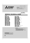
PART NAMES AND FUNCTIONS
MXZ-3B24NA MXZ-3B30NA MXZ-4B36NA
MXZ-2B20NA
Air inlet
(Back and side)
Air inlet
(Back and side)
Air outlet
Air outlet
Drain outlet
Drain outlet
2
3
SPECIFICATION
Outdoor model
Item
Capacity
Power
consumption
Cooling
Heating 47
Heating 17
Cooling
Heating 47
Heating 17
Cooling
Cooling
Heating
Heating
MXZ-2B20NA
Indoor type
Btu/h
Btu/h
Btu/h
W
W
W
Non-Duct (09+09)
Duct (09+12)
18,000
20,000
22,000
22,000
14,500
12,500
1,440
2,190
1,650
1,780
1,500
1,430
12.50
9.10
18.0
15.5
8.9 (7.0)
8.5 (6.9)
3.91
3.62
Munsell 3.0Y 7.8/1.1
208/230, 1, 60
20
15
0.96
SNB130FQBH1
U-V 0.98 V-W 0.98 W-U 0.98
10.1
15
LEV
49/51
Reverse cycle
33-1/16
13
27-15/16
130
Wireless type
12-24 V DC
Not supplied (optional parts)
1/4
A,B: 3/8
Flared
Flared
5 lb. 15 oz.
23.7 (NEO22)
EER
SEER
HSPF IV (V)
COP
External finish
V, phase, Hz
Power supply
Max. fuse size (time delay)
A
Min. circuit ampacity
A
Fan motor
F.L.A
Model
Winding resistance (at 68°F) Ω
Compressor
R.L.A
L.R.A
Refrigerant control
dB(A)
Sound level
Defrost method
W
in.
D
in.
Dimensions
H
in.
lb.
Weight
Remote controller
Control voltage (by built-in transformer)
Refrigerant piping
Liquid
in.
Valve size
Gas
in.
Indoor
Connection method
Outdoor
lb.
Refrigerant charge (R410A)
oz.
Refrigeration oil (Model)
NOTE : Test conditions are based on ARI 210/240.
Unit: °F
Mode
Cooling
Heating
Indoor air condition Outdoor air condition
Dry bulb Wet bulb Dry bulb Wet bulb
Test
1: "A" Cooling steady state at rated compressor speed
"B-2" Cooling steady state at rated compressor speed
"B-1" Cooling steady state at minimum compressor speed
Low ambient cooling steady state at minimum compressor speed
Intermediate cooling steady state at intermediate compressor speed
1: Standard rating-heating at rated compressor speed
2: Low temperature heating at maximum compressor speed
Maximum temperature heating at minimum compressor speed
High temperature heating at minimum compressor speed
Frost accumulation at rated compressor speed
Frost accumulation at intermediate compressor speed
3
80
80
80
80
80
70
70
70
70
70
70
67
67
67
67
67
60
60
60
60
60
60
95
82
82
67
87
47
17
62
47
35
35
(75)
(65)
(65)
(53.5)
(69)
43
15
56.5
43
33
33
Outdoor model
Item
Capacity
Power
consumption
Cooling
Heating 47
Heating 17
Cooling
Heating 47
Heating 17
Cooling
Cooling
Heating
Heating
Indoor type
Btu/h
Btu/h
Btu/h
W
W
W
EER
SEER
HSPF IV (V)
COP
External finish
Power supply
V, phase, Hz
Max. fuse size (time delay)
A
Min. circuit ampacity
A
Fan motor
F.L.A
Model
Winding resistance (at 68°F) Ω
Compressor
R.L.A
L.R.A
Refrigerant control
Sound level
dB(A)
Defrost method
W
in.
Dimensions
D
in.
H
in.
Weight
lb.
Remote controller
Control voltage (by built-in transformer)
Refrigerant piping
in.
Liquid
Valve size
in.
Gas
Indoor
Connection method
Outdoor
lb.
Refrigerant charge (R410A)
oz.
Refrigeration oil (Model)
MXZ-3B24NA
Non-Duct (06+06+09)
Duct (09+09+09)
22,000
23,600
25,000
24,600
18,800
17,000
1,760
2,460
1,750
1,900
2,120
2,230
12.50
9.60
17.5
15.0
9.3 (7.0)
8.5 (6.9)
4.20
3.80
Munsell 3.0Y 7.8/1.1
208/230, 1, 60
20
15
0.93
TNB220FMCH
U-V 0.61 V-W 0.61 W-U 0.61
11
15
LEV
54/49
Reverse cycle
35-7/16
12-19/32
35-7/16
150
Wireless type
12-24 V DC
Not supplied (optional parts)
1/4
A: 1/2 B,C: 3/8
Flared
Flared
7 lb. 11 oz.
29.4 (NEO22)
NOTE : Test conditions are based on ARI 210/240.
Unit: °F
Mode
Cooling
Heating
Indoor air condition Outdoor air condition
Dry bulb Wet bulb Dry bulb Wet bulb
Test
1: "A" Cooling steady state at rated compressor speed
"B-2" Cooling steady state at rated compressor speed
"B-1" Cooling steady state at minimum compressor speed
Low ambient cooling steady state at minimum compressor speed
Intermediate cooling steady state at intermediate compressor speed
1: Standard rating-heating at rated compressor speed
2: Low temperature heating at maximum compressor speed
Maximum temperature heating at minimum compressor speed
High temperature heating at minimum compressor speed
Frost accumulation at rated compressor speed
Frost accumulation at intermediate compressor speed
4
80
80
80
80
80
70
70
70
70
70
70
67
67
67
67
67
60
60
60
60
60
60
95
82
82
67
87
47
17
62
47
35
35
(75)
(65)
(65)
(53.5)
(69)
43
15
56.5
43
33
33
Outdoor model
Item
Capacity
Power
consumption
Cooling
Heating 47
Heating 17
Cooling
Heating 47
Heating 17
Cooling
Cooling
Heating
Heating
Indoor type
Btu/h
Btu/h
Btu/h
W
W
W
EER
SEER
HSPF IV (V)
COP
External finish
Power supply
V, phase, Hz
Max. fuse size (time delay)
A
Min. circuit ampacity
A
Fan motor
F.L.A
Model
Winding resistance (at 68°F) Ω
Compressor
R.L.A
L.R.A
Refrigerant control
Sound level
dB(A)
Defrost method
W
in.
Dimensions
D
in.
H
in.
Weight
lb.
Remote controller
Control voltage (by built-in transformer)
Refrigerant piping
in.
Liquid
Valve size
in.
Gas
Indoor
Connection method
Outdoor
lb.
Refrigerant charge (R410A)
oz.
Refrigeration oil (Model)
MXZ-3B30NA
Non-Duct (06+06+09)
Duct (09+09+09)
28,400
27,400
28,600
27,600
18,800
18,000
3,120
3,330
2,150
2,220
2,120
2,140
9.10
8.23
17.5
14.5
10.5 (7.2)
9.5 (7.0)
3.90
3.64
Munsell 3.0Y 7.8/1.1
208/230, 1, 60
20
15
0.93
TNB220FMCH
U-V 0.61 V-W 0.61 W-U 0.61
11
15
LEV
49/49
Reverse cycle
35-7/16
12-19/32
35-7/16
150
Wireless type
12-24 V DC
Not supplied (optional parts)
1/4
A: 1/2 B,C: 3/8
Flared
Flared
7 lb. 11 oz.
29.4 (NEO22)
Unit: °F
Mode
Cooling
Heating
Indoor air condition Outdoor air condition
Dry bulb Wet bulb Dry bulb Wet bulb
Test
1: "A" Cooling steady state at rated compressor speed
"B-2" Cooling steady state at rated compressor speed
"B-1" Cooling steady state at minimum compressor speed
Low ambient cooling steady state at minimum compressor speed
Intermediate cooling steady state at intermediate compressor speed
1: Standard rating-heating at rated compressor speed
2: Low temperature heating at maximum compressor speed
Maximum temperature heating at minimum compressor speed
High temperature heating at minimum compressor speed
Frost accumulation at rated compressor speed
Frost accumulation at intermediate compressor speed
5
80
80
80
80
80
70
70
70
70
70
70
67
67
67
67
67
60
60
60
60
60
60
95
82
82
67
87
47
17
62
47
35
35
(75)
(65)
(65)
(53.5)
(69)
43
15
56.5
43
33
33
Outdoor model
Item
Cooling
Capacity
Power
consumption
Indoor type
Btu/h
Heating 47
Btu/h
Heating 17
Cooling
Btu/h
W
Heating 47
W
W
Heating 17
EER
Cooling
SEER
Cooling
HSPF IV (V)
Heating
COP
Heating
External finish
V, phase, Hz
Power supply
A
Max. fuse size (time delay)
A
Min. circuit ampacity
F.L.A
Fan motor
Model
Winding resistance (at 68°F) Ω
Compressor
R.L.A
L.R.A
Refrigerant control
dB(A)
Sound level
Defrost method
W
in.
D
in.
Dimensions
H
in.
lb.
Weight
Remote controller
Control voltage (by built-in transformer)
Refrigerant piping
Liquid
in.
Valve size
Gas
in.
Indoor
Connection method
Outdoor
lb.
Refrigerant charge (R410A)
oz.
Refrigeration oil (Model)
MXZ-4B36NA
Non-Duct (09+09+09+09)
Duct (09+09+09+09)
35,400
34,400
36,000
34,400
208 V
208 V
36,000
34,400
230 V
230 V
24,600
25,400
3,760
3,940
3,020
3,100
208 V
208 V
3,020
3,100
230 V
230 V
3,450
3,340
9.40
8.70
18.0
15.0
9.3 (7.2)
9.0(7.0)
3.50
3.25
Munsell 3.0Y 7.8/1.1
208/230, 1, 60
20
19
0.93
TNB220FMCH
U-V 0.61 V-W 0.61 W-U 0.61
14.4
15
LEV
54/57
Reverse cycle
35-7/16
12-19/32
35-7/16
153
Wireless type
12-24 V DC
Not supplied (optional parts)
1/4
A: 1/2 B,C,D: 3/8
Flared
Flared
8 lb. 13 oz.
29.4 (NEO22)
NOTE : Test conditions are based on ARI 210/240.
Unit: °F
Mode
Cooling
Heating
Indoor air condition Outdoor air condition
Dry bulb Wet bulb Dry bulb Wet bulb
Test
1: "A" Cooling steady state at rated compressor speed
"B-2" Cooling steady state at rated compressor speed
"B-1" Cooling steady state at minimum compressor speed
Low ambient cooling steady state at minimum compressor speed
Intermediate cooling steady state at intermediate compressor speed
1: Standard rating-heating at rated compressor speed
2: Low temperature heating at maximum compressor speed
Maximum temperature heating at minimum compressor speed
High temperature heating at minimum compressor speed
Frost accumulation at rated compressor speed
Frost accumulation at intermediate compressor speed
6
80
80
80
80
80
70
70
70
70
70
70
67
67
67
67
67
60
60
60
60
60
60
95
82
82
67
87
47
17
62
47
35
35
(75)
(65)
(65)
(53.5)
(69)
43
15
56.5
43
33
33
NOISE CRITERIA CURVES
4
MXZ-2B20NA
FAN SPEED FUNCTION SPL(dB(A))
LINE
MXZ-3B24NA
Cooling
49
High
Cooling
54
High
Heating
51
High
Heating
49
OCTAVE BAND SOUND PRESSURE LEVEL, 0dB = 0.0002 MICRO BAR
OCTAVE BAND SOUND PRESSURE LEVEL, 0dB = 0.0002 MICRO BAR
80
70
NC-70
60
NC-60
50
NC-50
40
NC-40
30
NC-30
10
70
NC-70
60
NC-60
50
NC-50
40
NC-40
30
NC-30
20
APPROXIMATE
THRESHOLD OF
HEARING FOR
CONTINUOUS
NOISE
63
80
NC-20
10
125
250
500
1000
2000
4000
APPROXIMATE
THRESHOLD OF
HEARING FOR
CONTINUOUS
NOISE
63
8000
NC-20
125
MXZ-3B30NA
FAN SPEED FUNCTION SPL(dB(A))
1000
2000
4000
8000
FAN SPEED FUNCTION SPL(dB(A))
High
Cooling
49
High
Cooling
54
High
Heating
49
High
Heating
57
LINE
90
OCTAVE BAND SOUND PRESSURE LEVEL, 0dB = 0.0002 MICRO BAR
OCTAVE BAND SOUND PRESSURE LEVEL, 0dB = 0.0002 MICRO BAR
500
MXZ-4B36NA
LINE
90
80
70
NC-70
60
NC-60
50
NC-50
40
NC-40
30
NC-30
10
250
BAND CENTER FREQUENCIES, Hz
BAND CENTER FREQUENCIES, Hz
20
LINE
90
90
20
FAN SPEED FUNCTION SPL(dB(A))
High
70
NC-70
60
NC-60
50
NC-50
40
NC-40
30
NC-30
20
APPROXIMATE
THRESHOLD OF
HEARING FOR
CONTINUOUS
NOISE
63
80
NC-20
125
250
500
1000
2000
4000
10
8000
APPROXIMATE
THRESHOLD OF
HEARING FOR
CONTINUOUS
NOISE
63
NC-20
125
250
500
1000
2000
BAND CENTER FREQUENCIES, Hz
BAND CENTER FREQUENCIES, Hz
7
4000
8000
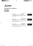
OUTLINES AND DIMENSIONS
5
MXZ-2B20NA
Unit: inch
6-21/32"
11-11/32"
14-3/16"
13/16"
17/32"
Side Air Intake
3- (1-5/16") Drain Hole
11/16"
Air
Discharge
15-19/32"
Rear Air
Intake
(Bolt Pitch)
9-3/16"
1-7/32"
21/32"
2-1/2"
19-11/16"
11/16"
6-9/16"
4-(13/32"×13/16") Oval Hole
(Foundation Bolt M10)
33-1/16"
1-3/16"
7-7/8"
1-3/16"
13"
1/2"
3- 7/8" Punched holes
(Connecting wire hole)
2-3/8"
2-5/8"
LIQ
14-1/4"
5-5/16"
1-25/32"
14-3/16"
27-15/16"
1-3/16"
9-7/16"
1-5/32"
GAS
LIQ
11-3/4"
1.Installation space
Note : Leave front and both sides
free of obstruction.
More than 19-11/16"
29/32"
LIQ 1/4"FLARE
GAS 3/8"FLARE
Unit A
3-5/16"
GAS
Unit B
More than 3-15/16"
Grounding terminal
Conduit
cover
More than 7-7/8"
More than 19-11/16"
2.Service space
More than 3-15/16"
More than13-25/32"
More than 3-15/16"
Note : Leave rear, overhead and both sides
free of obstruction.
Lock nut
Connector
More than 19-11/16"
Note : Leave front and overhead
free of obstruction.
More than 3-15/16"
More than 13-25/32"
8
SERVICE SPACE
More than 13-25/32"
MXZ-3B24NA
MXZ-3B30NA
Unit: inch
7-7/8"
7-7/8"
10-5/8"
Air in
5/8"
Air out
1-9/16"
Drain hole 3- 1-5/16"
14"
(Bolt pitch)
15-1/4"
5/8"
15/16" 7/16"
Air in
2-U Shaped notched hole
(Base bolt M10)
1-1/16"
1-3/8"
1-3/8"
2-29/32"
9-27/32"
19-11/16"
2-(15/32" x 1-13/32") Oval hole
(Base bolt M10)
3- 7/8"Punched hole
(Connect wiring hole)
35-7/16"
2- 7/8"Knockout
(Connect wiring hole)
Handle
1-3/16"
12-19/32"
13/32"
19-1/8"
B
A
Gas pipe
3/8 (B,C unit)
1/2 (A unit)
C unit connection
B unit connection
A unit connection
Liquid pipe
1/4 flared
More than 3-15/16"
More than 7-7/8"
Lock nut
Connector
Conduit cover
More than13-25/32"
More than 19-11/16"
More than 3-15/16"
2.Service space
More than 19-11/16"
Note : Leave front and overhead
free of obstruction.
Note : Leave rear, overhead and both sides
free of obstruction.
3-15/32"
C
More than 3-15/16"
Note : Leave front and both sides
free of obstruction.
More than 19-11/16"
1.Installation space
29/32"
5-3/16"
12-1/2"
1-25/32"
18-1/8"
8-27/32"
35-7/16"
4-3/4"
1-3/16"
Handle
More than 3-15/16"
More than 13-25/32"
9
SERVICE SPACE
More than 13-25/32"
MXZ-4B36NA
Unit: inch
7-7/8"
7-7/8"
10-5/8"
Air in
5/8"
Air out
1-9/16"
Drain hole 3- 1-5/16"
14"
(Bolt pitch)
15-1/4"
5/8"
15/16" 7/16"
Air in
2-U Shaped notched hole
(Base bolt M10)
1-1/16"
1-3/8"
1-3/8"
2-29/32"
9-27/32"
19-11/16"
2-(15/32" x 1-13/32") Oval hole
(Base bolt M10)
3- 7/8"Punched hole
(Connect wiring hole)
35-7/16"
2- 7/8"Knockout
(Connect wiring hole)
Handle
1-3/16"
12-19/32"
13/32"
4-3/4"
35-7/16"
D
19-1/8"
C
B
A
Gas pipe
3/8 (B,C,D unit)
1/2 (A unit)
D unit connection
C unit connection
B unit connection
A unit connection
Liquid pipe
1/4 flared
More than 3-15/16"
More than 7-7/8"
Lock nut
Connector
Conduit cover
More than13-25/32"
More than 19-11/16"
More than 3-15/16"
2.Service space
More than 19-11/16"
Note : Leave front and overhead
free of obstruction.
Note : Leave rear, overhead and both sides
free of obstruction.
3-15/32"
More than 3-15/16"
Note : Leave front and both sides
free of obstruction.
More than 19-11/16"
1.Installation space
29/32"
5-3/16"
12-1/2"
1-25/32"
18-1/8"
12-13/32"
1-3/16"
Handle
More than 3-15/16"
More than 13-25/32"
10
SERVICE SPACE
More than 13-25/32"
6
WIRING DIAGRAM
MXZ-2B20NA
MXZ-2B20NA -
1
11
MXZ-3B24NA
MXZ-3B30NA
MXZ-4B36NA
12
REFRIGERANT SYSTEM DIAGRAM
7
Unit: inch
MXZ-2B20NA
Service
port
Compressor
R.V. coil
OFF
ON
Refrigerant flow in cooling
Refrigerant flow in heating
Oil separator
Stop valve with
service port
Indoor unit
B
Discharge
temperature
thermistor RT62
Service
port
Capillary tube
O.D.0.10 x I.D.0.02 x 39.37
4-way valve
Muffler
Indoor unit
A
Outdoor heat
exchanger
temperature
thermistor
RT68
HEX-OUT
FAN-OUT
Indoor unit
A
Defrost
thermistor
RT61
Capillary tube
O.D.0.16 x I.D.0.11 x 3.93
Strainer
#100
Capillary tube
O.D.0.14 x I.D.0.09 x 19.68
LEV A
Stop valve
Strainer
#100
LEV E
Power
receiver
Indoor unit
B
Ambient
temperature
thermistor
RT65
Capillary tube
O.D.0.16 x I.D.0.11 x 3.93
Strainer
#100
LEV B
13
Strainer
#100
Distributor
Operating Range
MXZ-2B20NA
Maximum
Minimum
Maximum
Minimum
Cooling
Heating
Indoor intake air temperature Outdoor intake air temperature
115°FDB
95°FDB, 71°FWB
14°FDB
67°FDB, 57°FWB
75°FDB, 65°FWB
80°FDB, 67°FWB
6°FDB, 5°FWB
70°FDB, 60°FWB
MAX. REFRIGERANT PIPING LENGTH & PIPE SIZE SELECTION
MXZ-2B20NA
Piping length each indoor unit (a, b)
82 ft. MAX.
Total piping length (a+b)
164 ft. MAX.
Bending point for each unit
25 MAX.
Total bending point
50 MAX.
It is irrelevant which unit is higher.
Indoor
units
a
Max. height difference
Outdoor
unit
49 ft.
49 ft.
33 ft.
b
Refrigerant pipe diameter is different according to indoor unit to be connected. When using extension pipes, refer to the
tables below.
When the diameter of refrigerant pipe is different from that of outdoor unit union, use optional Different-diameter pipe.
For further information on Different-diameter pipe, see the appropriate parts catalog, Optional parts "DIFFERENT
DIAMETER PIPE"(2-1.).
Unit: inch
Indoor unit class
09 or less
12
15
Outdoor unit union diameter
For
Liquid
Indoor unit A
Gas
Liquid
Indoor unit B
Gas
Extension pipe diameter
Liquid
1/4
Gas
3/8
Liquid
1/4
Gas
3/8
Liquid
1/4
Gas
1/2
14
1/4
3/8
1/4
3/8
MXZ-3B24NA
MXZ-3B30NA
R.V. coil
OFF
ON
Unit: inch
Service port
Compressor
Service
port
Discharge
temperature
Refrigerant flow in cooling High-pressure
thermistor RT62
switch
Refrigerant flow in heating
Oil separator
Indoor unit
C
Stop valve
(with service port)
Indoor unit
B
Indoor unit
A
Muffler
Capillary tube
O.D.0.10 x I.D.0.02 x 39.37
4-way valve
Outdoor
heat
exchanger
Outdoor heat
exchanger
temperature
thermistor
RT68
Capillary tube
O.D.0.16 x I.D.0.11 x 3.94
Indoor unit
A
Indoor unit
B
Indoor unit
C
Strainer
#100
LEV A
Strainer
#100
LEV B
Strainer
#100
LEV C
Ambient
temperature
thermistor
RT65
Defrost
thermistor
RT61
Stop valve Strainer
#100
LEV F
Power
receiver
15
Strainer
#100
Capillary tube
O.D.0.12 x I.D.0.08 x 11.8
Distributor
Operating Range
MXZ-3B24NA MXZ-3B30NA
Indoor intake air temperature Outdoor intake air temperature
115°FDB
95°FDB, 71°FWB
14°FDB
67°FDB, 57°FWB
75°FDB, 65°FWB
80°FDB, 67°FWB
6°FDB, 5°FWB
70°FDB, 60°FWB
Maximum
Minimum
Maximum
Minimum
Cooling
Heating
MAX. REFRIGERANT PIPING LENGTH & PIPE SIZE SELECTION
MXZ-3B24NA MXZ-3B30NA
Piping length each indoor unit (a, b, c)
82 ft. MAX.
Total piping length (a+b+c)
230 ft. MAX.
Bending point for each unit
25 MAX.
Total bending point
70 MAX.
It is irrelevant which unit is higher.
Indoor
units
a
Max. height difference
Outdoor
unit
b
49 ft.
49 ft.
33 ft.
c
Refrigerant pipe diameter is different according to indoor unit to be connected. When using extension pipes, refer to the
tables below.
When the diameter of refrigerant pipe is different from that of outdoor unit union, use optional Different-diameter pipe.
For further information on Different-diameter pipe, see the appropriate parts catalog, Optional parts "DIFFERENT
DIAMETER PIPE"(2-1.).
Unit : inch
Outdoor unit union diameter
Indoor unit class
09 or less
12
15
17
18
24 (MXZ-3B30NA only)
For
Extension pipe diameter
Liquid
1/4
Gas
3/8
Liquid
1/4
Gas
3/8
Liquid
1/4
Gas
1/2
Liquid
1/4
Gas
1/2
Liquid
1/4
Gas
1/2
Liquid
1/4
Gas
5/8
Indoor unit A
Indoor unit B
Indoor unit C
16
Liquid
1/4
Gas
1/2
Liquid
1/4
Gas
3/8
Liquid
1/4
Gas
3/8
MXZ-4B36NA
R.V. coil
OFF
ON
Unit: inch
Service port
Compressor
Service
port
Discharge
temperature
Refrigerant flow in cooling High-pressure
thermistor RT62
switch
Refrigerant flow in heating
Oil separator
Indoor unit
D
Stop valve
(with service port)
Indoor unit
C
Indoor unit
B
Indoor unit
A
Capillary tube
O.D.0.10 x I.D.0.02 x 39.37
4-way valve
Muffler
Outdoor
heat
exchanger
Outdoor heat
exchanger
temperature
thermistor
RT68
Capillary tube
O.D.0.16 x I.D.0.11 x 3.94
Indoor unit
A
Indoor unit
B
Indoor unit
C
Indoor unit
D
Strainer
#100
Defrost
thermistor
RT61
LEV A
Strainer
#100
LEV B
Strainer
#100
LEV C
Strainer
#100
LEV D
Ambient
temperature
thermistor
RT65
Stop valve Strainer
#100
LEV F
Power
receiver
17
Strainer
#100
Capillary tube
O.D.0.12 x I.D.0.08 x 11.8
Distributor
Operating Range
MXZ-4B36NA
Indoor intake air temperature Outdoor intake air temperature
115°FDB
95°FDB, 71°FWB
14°FDB
67°FDB, 57°FWB
75°FDB, 65°FWB
80°FDB, 67°FWB
6°FDB, 5°FWB
70°FDB, 60°FWB
Maximum
Minimum
Maximum
Minimum
Cooling
Heating
MAX. REFRIGERANT PIPING LENGTH & PIPE SIZE SELECTION
MXZ-4B36NA
Piping length each indoor unit (a, b, c, d)
82 ft. MAX.
Total piping length (a+b+c+d)
230 ft. MAX.
Bending point for each unit
25 MAX.
Total bending point
70 MAX.
It is irrelevant which unit is higher.
Indoor
units
a
Max. height difference
b
Outdoor
unit
49 ft.
49 ft.
c
33 ft.
d
Refrigerant pipe diameter is different according to indoor unit to be connected. When using extension pipes, refer to the
tables below.
When the diameter of refrigerant pipe is different from that of outdoor unit union, use optional Different-diameter pipe.
For further information on Different-diameter pipe, see the appropriate parts catalog, Optional parts "DIFFERENT
DIAMETER PIPE"(2-1.).
Unit : inch
Indoor unit class
09 or less
12
15
17
18
24
Extension pipe diameter
Liquid
1/4
Gas
3/8
Liquid
1/4
Gas
3/8
Liquid
1/4
Gas
1/2
Liquid
1/4
Gas
1/2
Liquid
1/4
Gas
1/2
Liquid
1/4
Gas
5/8
Outdoor unit union diameter
For
Indoor unit A
Indoor unit B
Indoor unit C
Indoor unit D
18
Liquid
1/4
Gas
1/2
Liquid
1/4
Gas
3/8
Liquid
1/4
Gas
3/8
Liquid
1/4
Gas
3/8
8
DATA
MXZ-2B20NA
Model
Indoor type
Item
Total
Capacity
SHF
Input
Electrical
Power supply (V,phase,Hz)
circuit
Input
Comp. current (208/230V)
Fan motor current
Refrigerant Condensing pressure
circuit
Suction pressure
Discharge temperature
Condensing temperature
Suction temperature
Comp. shell bottom temp.
Ref. pipe length
[Total pipe length for multi-system]
Refrigerant charge (R410A)
Outdoor
Intake air temperature
DB
unit
WB
Fan speed
Airflow
kW
A
A
PSIG
PSIG
ºF
ºF
ºF
ºF
Non-Duct (09+09)
Duct (09+12)
Cooling
Heating
Cooling
Heating
18,000
22,000
20,000
22,000
–
–
–
–
1.44
1.65
2.19
1.78
208/230, 1, 60
1.396
1.604
2.06
1.69
6.08/5.87
7.25/6.80
9.81/8.87
7.98/7.22
0.43/0.39
0.43/0.39
0.43/0.39
0.43/0.39
411
319
417
350
141
102
130
101
169
154
174
172
114
100
120
104
71
46
65
46
163
149
185
167
ft
25 [50]
Unit
But/h
–
kW
–
ºF
ºF
rpm
CFM
5 lb. 15 oz.
95
–
650
1485
95
–
650
1485
47
43
700
1640
MXZ-3B24NA
Model
Indoor type
Item
Total
Capacity
SHF
Input
Electrical
Outdoor unit
circuit
Power supply (V,phase,Hz)
Input
Comp. current (208/230V)
Fan motor current
Refrigerant Condensing pressure
circuit
Suction pressure
Discharge temperature
Condensing temperature
Suction temperature
Comp. shell bottom temp.
Ref. pipe length
[Total pipe length for multi-system]
Refrigerant charge (R410A)
Outdoor
Intake air temperature
DB
unit
WB
Fan speed
Airflow
47
43
700
1640
kW
A
A
PSIG
PSIG
ºF
ºF
ºF
ºF
Non-Duct (06+06+09)
Duct (09+09+09)
Cooling
Heating
Cooling
Heating
22,000
25,000
23,600
24,600
–
–
–
–
1.76
1.75
2.46
1.9
MXZ-3B24NA
208/230,1,60
1.694
1.681
2.28
1.78
8.00/7.23
7.94/7.18
10.90/9.86
8.43/7.62
0.43/0.39
0.43/0.39
0.43/0.39
0.43/0.39
394
296
408
324
158
98
139
100
173
153
167
164
115
93
117
99
79
47
58
49
159
134
153
144
ft
25[75]
–
ºF
ºF
rpm
CFM
7 lb.11 oz.
Unit
But/h
–
kW
95
–
750
2,068
19
47
43
600
1,605
95
–
750
2,068
47
43
600
1,605
MXZ-3B30NA
Model
Indoor type
Item
Total
Capacity
SHF
Input
Electrical
Outdoor unit
circuit
Power supply (V,phase,Hz)
Input
Comp. current (208/230V)
Fan motor current
Refrigerant Condensing pressure
circuit
Suction pressure
Discharge temperature
Condensing temperature
Suction temperature
Comp. shell bottom temp.
Ref. pipe length
[Total pipe length for multi-system]
Refrigerant charge (R410A)
Outdoor
Intake air temperature
DB
unit
WB
Fan speed
Airflow
kW
A
A
PSIG
PSIG
ºF
ºF
ºF
ºF
Non-Duct (09+09+12)
Duct (09+09+09)
Cooling
Heating
Cooling
Heating
28,400
28,600
27,400
27,600
–
–
–
–
3.12
2.15
3.33
2.22
MXZ-3B30NA
208/230,1,60
3.047
2.081
3.14
2.09
14.71/13.30
9.92/8.97
15.17/13.72
10.36/9.37
0.43/0.39
0.43/0.39
0.43/0.39
0.43/0.39
489
313
496
325
145
94
137
100
208
155
203
168
130
97
133
99
77
40
63
50
186
136
188
152
ft
25[75]
Unit
But/h
–
kW
–
ºF
ºF
rpm
CFM
7 lb.11 oz.
95
–
520
1,365
95
–
520
1,365
47
43
600
1,605
MXZ-4B36NA
Model
Indoor type
Item
Total
Capacity
SHF
Input
Electrical
Outdoor unit
circuit
Power supply (V,phase,Hz)
Input
Comp. current (208/230V)
Fan motor current
Refrigerant Condensing pressure
circuit
Suction pressure
Discharge temperature
Condensing temperature
Suction temperature
Comp. shell bottom temp.
Ref. pipe length
[Total pipe length for multi-system]
Refrigerant charge (R410A)
Outdoor
Intake air temperature
DB
unit
WB
Fan speed
Airflow
47
43
600
1,605
kW
A
A
PSIG
PSIG
ºF
ºF
ºF
ºF
Non-Duct (09+09+09+09)
Duct (09+09+09+09)
Cooling
Heating
Cooling
Heating
35,400
36,000
34,400
34,400
–
–
–
–
3.76
3.02
3.94
3.1
MXZ-4B36NA
208/230,1,60
3.672
2.928
3.62
2.86
17.44/15.78
13.83/12.51
17.58/15.90
13.39/12.56
0.43/0.39
0.43/0.39
0.43/0.39
0.43/0.39
485
309
455
347
142
91
130
95
198
139
202
163
129
95
126
102
66
28
65
32
184
127
186
148
ft
25[100]
–
ºF
ºF
rpm
CFM
8 lb.13 oz.
Unit
But/h
–
kW
95
–
750
2,068
20
47
43
750
2,068
95
–
750
2,068
47
43
750
2,068
8-1. OPERATING RANGE
(1) POWER SUPPLY
Model
MXZ-2B20NA
MXZ-3B24NA
MXZ-3B30NA
MXZ-4B36NA
Outdoor unit
Guaranteed Voltage
Rating
Min. 198 V 208 V 230 V Max. 253 V
208/230 V 60 Hz 1
(2) OPERATION
Function
Cooling
Heating
Intake air
temperature
Condition
"A" Cooling steady state
at rated compressor speed
"B-2" Cooling steady state
at rated compressor speed
"B-1" Cooling steady state
at minimum compressor speed
Low ambient cooling steady state
at minimum compressor speed
Intermediate cooling steady state
at intermediate compressor speed
Standard rating-heating
at rated compressor speed
Low temperature heating
at rated compressor speed
Max. temperature heating
at minimum compressor speed
High temperature heating
at minimum compressor speed
Frost accumulation
at rated compressor speed
Frost accumulation
at intermediate compressor speed
Outdoor
Indoor
DB (°F)
WB (°F)
DB (°F)
WB (°F)
80
67
95
(75)
80
67
82
(65)
80
67
82
(65)
80
67
67
(53.5)
80
67
87
(69)
70
60
47
43
70
60
17
15
70
60
62
56.5
70
60
47
43
70
60
35
33
70
60
35
33
21
MXZ-2B20NA MXZ-3B24NA MXZ-3B30NA MXZ-4B36NA
The standard specifications apply only to the operation of the air conditioner under normal conditions.
Since operating conditions vary according to the areas where these units are installed, the following information has been provided to clarify the operating characteristics of the air conditioner under the conditions indicated by the performance curve.
(1) GUARANTEED VOLTAGE
198 ~ 253 V 60 Hz
(2) AIR FLOW
Air flow should be set at MAX.
(3) MAIN READINGS
(1) Indoor intake air wet-bulb temperature :
(2) Indoor outlet air wet-bulb temperature :
(3) Outdoor intake air dry-bulb temperature :
(4) Total input:
°FWB
°FWB
°FDB
W
}
Cooling
}
(5) Indoor intake air dry-bulb temperature :
°FDB
Heating
(6) Outdoor intake air wet-bulb temperature :
°FWB
(7) Total input :
W
Indoor air wet/dry-bulb temperature difference on the left side of the following chart shows the difference between the
indoor intake air wet/dry-bulb temperature and the indoor outlet air wet/dry-bulb temperature for your reference at service.
How to measure the indoor air wet-bulb/dry-bulb temperature difference
1.
2.
3.
4.
5.
6.
7.
8.
Attach at least 2 sets of wet and dry-bulb thermometers to the indoor air intake as shown in the figure, and at least 2 sets
of wet and dry-bulb thermometers to the indoor air outlet. The thermometers must be attached to the position where air
speed is high.
Attach at least 2 sets of wet and dry-bulb thermometers to the outdoor air intake.
Cover the thermometers to prevent direct rays of the sun.
Check that the air filter is cleaned.
Open windows and doors of room.
Press the EMERGENCY OPERATION switch once (twice) to start the EMERGENCY COOL (HEAT) MODE.
Compressor starts running at 33 Hz (COOL) or 45 Hz (HEAT). The frequency at each operation mode is fixed.
When system stabilizes after more than 15 minutes, measure temperature and take an average temperature.
10 minutes later, measure temperature again and check that the temperature does not change.
INDOOR UNIT
OUTDOOR UNIT
Wet-and dry-bulb
thermometers
22
Wet-and dry-bulb
thermometers
8-2. CAPACITY AND THE INPUT CURVES
MXZ-2B20NA
13.1
6.1
9.5 11.5
12.1
5.6
8.6 10.4
11.2
5.0
7.9
9.5
10.1
4.7
7.0
8.6
9.0
4.1
6.3
7.6
8.1
Capacity correction factors
10.3 12.4
1.5
Indoor intake air Wet-bulb
temperature(°F)
1.4
1.3
1.2
79
1.1
75
1.0
72
68
64
113
0.9
15 class
(69Hz)
6.7
12 class
(50Hz)
14.4
09 class
(35Hz)
11.2 13.5
06 class
(25Hz)
Indoor unit class
(Inverter output
frequency)
Indoor air WB temperature
difference (degree)
Cooling capacity (at Rated frequency)
7.2
14
23
32
41
50
59
68
77
86
95
104
Outdoor intake air Dry-bulb temperature(°F)
Total input (Cooling : at Rated frequency)
Input correction factors
1.3
1.2
72
68
64
75
79
1.1
1.0
0.9
Indoor intake air Wet-bulb
temperature( F)
0.8
14
23
32
41
50
59
68
77
86
95
104
113
Heating capacity (at Rated frequency)
1.2
e(
tur
1.1
era
1.0
bu
ry-
lb
°F)
59
68
79
p
tem
ir D
0.9
a
ke
ta
0.8
r in
oo
Ind
0.7
0.6
0.5
Total input (Heating : at Rated frequency)
1.3
Input correction factor
1.3
Capacity correction factor
47.5
43.7
40.1
36.5
32.8
29.2
25.6
22.0
18.2
14.6
15 class
(78Hz)
40.9
37.6
34.6
31.3
28.3
25.0
22.0
18.9
15.7
12.6
12 class
(59Hz)
32.8
30.2
27.7
25.2
22.7
20.2
17.6
15.1
12.6
10.1
09 class
(47Hz)
22.1
20.5
18.7
17.1
15.3
13.7
11.9
10.3
8.5
6.8
06 class
(31Hz)
Indoor unit class
(Inverter output
frequency)
Indoor air DB temperature
difference (degree)
Outdoor intake air Dry-bulb temperature (°F)
1.2
F)
re (°
1.1
1.0
inta
oor
79
68
59
lb te
y-bu
ir Dr
ke a
0.9
ratu
mpe
Ind
0.8
0.7
0.6
0.5
0.4
0.4
5
14
23
32
41
50
Outdoor intake air Wet-bulb temperature (°F)
59
5
14
23
32
41
50
Outdoor intake air Wet-bulb temperature (°F)
59
NOTE: The above broken lines are for the heating operation without any frost and defrost operation.
23
MXZ-3B24NA MXZ-3B30NA MXZ-4B36NA
19.3
7.2
10.3 12.4
12.2 15.5
17.8
6.7
9.5 11.5
11.2 14.2
16.2
6.1
8.6 10.4
10.3 13.0
14.8
5.6
7.9
9.5
9.4 11.7
13.3
5.0
7.0
8.6
8.5 10.6
12.1
4.5
6.3
7.6
7.6
10.6
09 class
(20Hz)
12 class
(29Hz)
15 class
(33Hz)
18 class
(49Hz)
9.4
1.5
Capacity correction factors
13.1 16.7
Indoor intake air Wet-bulb
temperature(°F)
1.4
1.3
1.2
79
1.1
75
1.0
72
68
64
113
0.9
*24 class
(56Hz)
11.2 13.5
06 class
(15Hz)
Indoor unit class
(Inverter output
frequency)
Indoor air WB temperature
difference (degree)
Cooling capacity (at Rated frequency)
7.7
14
23
32
41
50
59
68
77
86
95
104
Outdoor intake air Dry-bulb temperature(°F)
Total input (Cooling : at Rated frequency)
Input correction factors
1.3
1.2
72
68
64
75
79
1.1
1.0
0.9
Indoor intake air Wet-bulb
temperature( F)
0.8
14
23
32
41
50
59
68
77
86
95
104
113
Heating capacity (at Rated frequency)
1.2
era
1.0
ir
ea
0.9
0.8
Ind
0.7
oo
r in
ulb
°F)
e(
tur
1.1
59
68
779
p
tem
y-b
Dr
tak
0.6
0.5
Total input (Heating : at Rated frequency)
1.3
Input correction factor
1.3
Capacity correction factor
47.3
43.7
40.1
36.4
32.8
29.2
25.6
21.8
18.2
14.6
*24 class
(72Hz)
51.5
47.5
43.6
39.6
35.6
31.7
27.7
23.8
19.8
15.8
18 class
(50Hz)
47.5
43.7
40.1
36.5
32.8
29.2
25.6
22.0
18.2
14.6
15 class
(44Hz)
43.2
40.0
36.5
33.3
29.9
26.6
23.2
20.0
16.6
13.3
12 class
(32Hz)
32.8
30.2
27.7
25.2
22.7
20.2
17.6
15.1
12.6
10.1
09 class
(26Hz)
23.4
21.6
19.8
18.0
16.2
14.4
12.6
10.8
9.0
7.2
06 class
(18Hz)
Indoor unit class
(Inverter output
frequency)
Indoor air DB temperature
difference (degree)
Outdoor intake air Dry-bulb temperature (°F)
1.2
1.1
F)
re (°
1.0
lb
y-bu
ir Dr
tu
pera
79
68
59
tem
ke a
0.9
ta
or in
Indo
0.8
0.7
0.6
0.5
0.4
0.4
5
14
23
32
41
50
Outdoor intake air Wet-bulb temperature (°F)
59
5
14
23
32
41
50
Outdoor intake air Wet-bulb temperature (°F)
59
* MXZ-3B30/4B36NA only
NOTE: The above broken lines are for the heating operation without any frost and defrost operation.
24
8-3. CAPACITY AND INPUT CORRECTION BY MEANS OF INVERTER OUTPUT FREQUENCY
(OUTDOOR UNIT: MXZ-2B20NA)
1. 06-class unit in single operation
<COOL>Capacity
2.0
<COOL>Total input
2.0
1.5
1.5
1.0
1.0
0.5
0.5
0
50
0
100 Hz
Frequency
50
Frequency
<HEAT>Capacity
2.5
<HEAT>Total input
2.5
2.0
2.0
1.5
1.5
1.0
1.0
0.5
0.5
100 Hz
0
50
100 Hz
0
Frequency
50
Frequency
100 Hz
2. 09-class unit in single operation
<COOL>Capacity
2.0
<COOL>Total input
2.0
<HEAT>Capacity
2.0
1.5
1.5
1.5
1.5
1.0
1.0
1.0
1.0
0.5
0.5
0.5
0.5
0
50
0
100 Hz
Frequency
50
Frequency
100 Hz
0
50
<HEAT>Total input
2.0
100 Hz
0
Frequency
50
Frequency
100 Hz
3. 12-class unit in single operation
<COOL>Capacity
2.0
<COOL>Total input
2.0
<HEAT>Capacity
2.0
1.5
1.5
1.5
1.5
1.0
1.0
1.0
1.0
0.5
0.5
0.5
0.5
0
50
100 Hz
0
Frequency
50
Frequency
100 Hz
0
50
<HEAT>Total input
2.0
0
100 Hz
Frequency
50
Frequency
100 Hz
4. 15-class unit in single operation
<COOL>Capacity
2.0
<COOL>Total input
2.0
<HEAT>Capacity
2.0
1.5
1.5
1.5
1.5
1.0
1.0
1.0
1.0
0.5
0.5
0.5
0.5
0
50
Frequency
100 Hz
0
50
Frequency
100 Hz
25
0
50
Frequency
<HEAT>Total input
2.0
100 Hz
0
50
Frequency
100 Hz
(OUTDOOR UNIT: MXZ-3B24NA MXZ-3B30NA MXZ-4B36NA)
1. 06-class unit in single operation
<COOL>Capacity
2.0
<COOL>Total input
2.0
<HEAT>Capacity
2.0
1.5
1.5
1.5
1.0
1.0
1.0
<HEAT>Total input
2.5
2.0
1.5
1.0
0.5
0.5
0
50
0.5
0
100 Hz
Frequency
50
Frequency
100 Hz
0.5
0
50
100 Hz
0
Frequency
50
Frequency
100 Hz
2. 09-class unit in single operation
<COOL>Capacity
2.0
<COOL>Total input
2.0
<HEAT>Capacity
2.0
1.5
1.5
1.5
1.5
1.0
1.0
1.0
1.0
0.5
0.5
0.5
0.5
0
50
0
100 Hz
Frequency
50
Frequency
100 Hz
0
50
<HEAT>Total input
2.0
100 Hz
0
Frequency
50
Frequency
100 Hz
3. 12-class unit in single operation
<COOL>Capacity
2.0
<COOL>Total input
2.0
<HEAT>Capacity
2.0
1.5
1.5
1.5
1.5
1.0
1.0
1.0
1.0
0.5
0.5
0.5
0.5
0
50
100 Hz
0
Frequency
50
Frequency
100 Hz
0
50
<HEAT>Total input
2.0
0
100 Hz
Frequency
50
Frequency
100 Hz
4. 15-class unit in single operation
<COOL>Capacity
2.0
<COOL>Total input
2.0
<HEAT>Capacity
2.0
1.5
1.5
1.5
1.5
1.0
1.0
1.0
1.0
0.5
0.5
0.5
0.5
0
50
0
100 Hz
Frequency
50
Frequency
100 Hz
0
50
<HEAT>Total input
2.0
100 Hz
0
Frequency
50
Frequency
100 Hz
5. 18-class unit in single operation
<COOL>Capacity
2.0
<COOL>Total input
2.0
<HEAT>Capacity
2.0
1.5
1.5
1.5
1.5
1.0
1.0
1.0
1.0
0.5
0.5
0.5
0.5
0
50
100 Hz
0
Frequency
50
Frequency
100 Hz
0
50
<HEAT>Total input
2.0
100 Hz
0
Frequency
50
Frequency
100 Hz
6. 24-class unit in single operation (MXZ-3B30/4B36NA only)
<COOL>Capacity
2.0
<COOL>Total input
2.0
<HEAT>Capacity
2.0
1.5
1.5
1.5
1.5
1.0
1.0
1.0
1.0
0.5
0.5
0.5
0.5
0
50
Frequency
100 Hz
0
50
Frequency
100 Hz
0
50
Frequency
26
<HEAT>Total input
2.0
100 Hz
0
50
Frequency
100 Hz
8-4. OUTDOOR LOW PRESSURE AND OUTDOOR UNIT CURRENT
1. 06-class unit in single operation (OUTDOOR UNIT: MXZ-2B20NA)
(1) COOL operation
Data is based on the condition of indoor humidity
50%
Air flow speed: High
Inverter output frequency: 40 Hz
<How to work fixed-frequency operation>
1. Set emergency switch to COOL or HEAT. The switch is located
on indoor unit.
2. Press emergency run ON/OFF button.
3. Compressor starts running at 40 Hz (COOL) or 48 Hz (HEAT).
4. Indoor fan runs at High speed and continues for 30 minutes.
5. To cancel this operation, press emergency run ON/OFF button
or any button on remote controller.
(PSIG)
170
perature
In
tem
door DB
(°F)
150
140
130
86
80
75
Outdoor unit current (A)
Outdoor low pressure
160
6.0
70
4.0
ure
erat
p
m
e
(°F)
Bt
or D
Indo
3.0
86
80
75
70
40 Hz
2.0
1.0
40 Hz
120
65 70 75 80 85 90 95 100 105 110 115 (°F)
0.0
65 70 75 80 85 90 95 100 105 110 115 (°F)
Ambient temperature (°F)
7.0
Outdoor unit current (A)
Ambient temperature (°F)
(2) HEAT operation
Data is based on the condition of indoor humidity
75%
Set air flow to High speed.
Inverter output frequency is 48 Hz.
5.0
6.0
5.0
4.0
F)
re (°
r DB
o
Indo
te
ratu
mpe
75
70
65
3.0
48 Hz
2.0
15 20 25 30 35 40 45 50 55 60 65 70 75 (°F)
Ambient temperature (°F)
27
2. 09-class unit in single operation (OUTDOOR UNIT: MXZ-2B20NA)
(1) COOL operation
Data is based on the condition of indoor humidity
50%
Air flow speed: High
Inverter output frequency: 40 Hz
<How to work fixed-frequency operation>
1. Set emergency switch to COOL or HEAT. The switch is located
on indoor unit.
2. Press emergency run ON/OFF button.
3. Compressor starts running at 40 Hz (COOL) or 48 Hz (HEAT).
4. Indoor fan runs at High speed and continues for 30 minutes.
5. To cancel this operation, press emergency run ON/OFF button
or any button on remote controller.
(PSIG)
170
86
80
150
140
75
130
Outdoor unit current (A)
re (°F)
mperatu
DB te
Indoor
70
5.0
F)
re (°
4.0
tu
pera
m
B te
or D
Indo
3.0
86
80
75
70
40 Hz
2.0
1.0
40 Hz
120
65 70 75 80 85 90 95 100 105 110 115 (°F)
0.0
65 70 75 80 85 90 95 100 105 110 115 (°F)
Ambient temperature (°F)
Ambient temperature (°F)
(2) HEAT operation
Data is based on the condition of indoor humidity
75%
Set air flow to High speed.
Inverter output frequency is 48 Hz.
7.0
Outdoor unit current (A)
Outdoor low pressure
160
6.0
6.0
5.0
ture
4.0
B
or D
Indo
era
temp
(°F)
75
70
65
3.0
48 Hz
2.0
15 20 25 30 35 40 45 50 55 60 65 70 75 (°F)
Ambient temperature (°F)
28
3. 12-class unit in single operation (OUTDOOR UNIT: MXZ-2B20NA)
(1) COOL operation
Data is based on the condition of indoor humidity
50%
Air flow speed: High
Inverter output frequency: 40 Hz
160
r DB
Indoo
6.0
(˚F)
rature
e
temp
86
80
150
75
140
5.0
Outdoor unit current (A)
Outdoor low pressure
(PSIG)
170
<How to work fixed-frequency operation>
1. Set emergency switch to COOL or HEAT. The switch is located
on indoor unit.
2. Press emergency run ON/OFF button.
3. Compressor starts running at 40 Hz (COOL) or 48 Hz (HEAT).
4. Indoor fan runs at High speed and continues for 30 minutes.
5. To cancel this operation, press emergency run ON/OFF button
or any button on remote controller.
70
130
ure
rat
mpe
4.0
(˚F)
86
80
75
70
te
r DB
o
Indo
3.0
40 Hz
2.0
1.0
40 Hz
120
0.0
65 70 75 80 85 90 95 100 105 110 115 (˚F) 65 70 75 80 85 90 95 100 105 110 115 (˚F)
Ambient temperature (˚F)
Ambient temperature (˚F)
(2) HEAT operation
Data is based on the condition of indoor humidity
75%
Set air flow to High speed.
Inverter output frequency is 48 Hz.
Outdoor unit current (A)
7.0
6.0
5.0
4.0
F
re (˚
ratu
e
p
m
B te
or D
o
d
n
I
)
75
70
65
3.0
48 Hz
2.0
15 20 25 30 35 40 45 50 55 60 65 70 75 (˚F)
Ambient temperature (˚F)
29
4. 15-class unit in single operation (OUTDOOR UNIT: MXZ-2B20NA)
(1) COOL operation
Data is based on the condition of indoor humidity
50%
Air flow speed: High
Inverter output frequency: 40 Hz
160
F
ure (˚
perat
m
e
t
r DB
Indoo
6.0
)
86
5.0
80
150
75
140
Outdoor unit current (A)
Outdoor low pressure
(PSIG)
170
<How to work fixed-frequency operation>
1. Set emergency switch to COOL or HEAT. The switch is located
on indoor unit.
2. Press emergency run ON/OFF button.
3. Compressor starts running at 40 Hz (COOL) or 48 Hz (HEAT).
4. Indoor fan runs at High speed and continues for 30 minutes.
5. To cancel this operation, press emergency run ON/OFF button
or any button on remote controller.
4.0
3.0
or
Indo
F
re (˚
eratu
p
m
e
DB t
86
80
75
70
)
40 Hz
2.0
70
130
1.0
40 Hz
120
0.0
65 70 75 80 85 90 95 100 105 110 115 (˚F) 65 70 75 80 85 90 95 100 105 110 115 (˚F)
Ambient temperature (˚F)
Ambient temperature (˚F)
(2) HEAT operation
Data is based on the condition of indoor humidity
75%
Set air flow to High speed.
Inverter output frequency is 48 Hz.
Outdoor unit current (A)
7.0
6.0
5.0
4.0
3.0
( ˚F
ture
a
r
e
mp
B te
or D
o
d
In
)
75
70
65
48 Hz
2.0
15 20 25 30 35 40 45 50 55 60 65 70 75 (˚F)
Ambient temperature (˚F)
30
5. 06-class unit in single operation (OUTDOOR UNIT : MXZ-3B24NA MXZ-3B30NA MXZ-4B36NA)
(1) COOL operation
Data is based on the condition of indoor
<How to work fixed-frequency operation>
humidity 50%
1. Set emergency switch to COOL or HEAT. The switch is located
Air flow speed : High
on indoor unit.
Inverter output frequency : 24 Hz
2. Press emergency run ON/OFF button.
3. Compressor starts running at 24 Hz (COOL) or 32 Hz (HEAT).
4. Indoor fan runs at High speed and continues for 30 minutes.
5. To cancel this operation, press emergency run ON/OFF button
or any button on remote controller.
Outdoor low pressure
150
80
140
75
130
70
120
6.0
86
)
e (˚F
ratur
e
p
B tem
or D
Indo
Outdoor unit current (A)
(PSIG)
160
24 Hz
5.0
4.0
)
e (˚F
ratur
e
p
B tem
or D
Indo
86
80
75
70
24 Hz
3.0
2.0
1.0
110
65 70 75 80 85 90 95 100 105 110 115 (˚F)
0.0
65 70 75 80 85 90 95 100 105 110 115 (˚F)
Ambient temperature (˚F)
Ambient temperature (˚F)
(2) HEAT operation
Data is based on the condition of outdoor
humidity 75%.
Set air flow to High speed.
Inverter output frequency is 32 Hz.
Outdoor unit current (A)
7.0
6.0
5.0
4.0
e(
tur
a
r
pe
tem
B
rD
oo
d
n
I
˚F)
75
70
65
32 Hz
3.0
2.0
15 20 25 30 35 40 45 50 55 60 65 70 75 (˚F)
Ambient temperature (˚F)
31
6. 09-class unit in single operation (OUTDOOR UNIT : MXZ-3B24NA MXZ-3B30NA MXZ-4B36NA)
(1) COOL operation
Data is based on the condition of indoor
<How to work fixed-frequency operation>
humidity 50%
1. Set emergency switch to COOL or HEAT. The switch is located
Air flow speed : High
on indoor unit.
Inverter output frequency : 24 Hz
2. Press emergency run ON/OFF button.
3. Compressor starts running at 24 Hz (COOL) or 32 Hz (HEAT).
4. Indoor fan runs at High speed and continues for 30 minutes.
5. To cancel this operation, press emergency run ON/OFF button
or any button on remote controller.
Outdoor low pressure
150
e ( ˚F
ratur
e
p
B tem
or D
Indo
80
140
75
130
70
120
6.0
86
)
Outdoor unit current (A)
(PSIG)
160
24 Hz
5.0
ture
4.0
B
or D
Indo
era
temp
(˚F)
86
80
75
70
24 Hz
3.0
2.0
1.0
0.0
65 70 75 80 85 90 95 100 105 110 115 (˚F)
110
65 70 75 80 85 90 95 100 105 110 115 (˚F)
(2) HEAT operation Ambient temperature (˚F)
Data is based on the condition of outdoor
humidity 75%.
Set air flow to High speed.
Inverter output frequency is 32 Hz.
Ambient temperature (˚F)
Outdoor unit current (A)
7.0
6.0
5.0
4.0
e(
tur
a
r
pe
tem
B
rD
oo
d
n
I
˚F)
75
70
65
32 Hz
3.0
2.0
15 20 25 30 35 40 45 50 55 60 65 70 75 (˚F)
Ambient temperature (˚F)
32
7. 12-class unit in single operation (OUTDOOR UNIT : MXZ-3B24NA MXZ-3B30NA MXZ-4B36NA)
(1) COOL operation
Data is based on the condition of indoor
humidity 50%
Air flow speed : High
Inverter output frequency : 24 Hz
150
r
Indoo
86
(˚F)
rature
e
p
m
DB te
5.0
80
140
75
130
120
6.0
70
Outdoor unit current (A)
Outdoor low pressure
(PSIG)
160
<How to work fixed-frequency operation>
1. Set emergency switch to COOL or HEAT. The switch is located
on indoor unit.
2. Press emergency run ON/OFF button.
3. Compressor starts running at 24 Hz (COOL) or 32 Hz (HEAT).
4. Indoor fan runs at High speed and continues for 30 minutes.
5. To cancel this operation, press emergency run ON/OFF button
or any button on remote controller.
24 Hz
4.0
F
re (˚
ratu
e
p
m
B te
or D
o
d
In
)
86
80
75
70
3.0
24 Hz
2.0
1.0
110
0.0
65 70 75 80 85 90 95 100 105 110 115 (˚F) 65 70 75 80 85 90 95 100 105 110 115 (˚F)
Ambient temperature (˚F)
Ambient temperature (˚F)
(2) HEAT operation
Data is based on the condition of outdoor
humidity 75%.
Set air flow to High speed.
Inverter output frequency is 32 Hz.
Outdoor unit current (A)
7.0
6.0
5.0
4.0
(
re
atu
r
e
p
em
Bt
D
oor
Ind
75
70
65
˚F)
32 Hz
3.0
2.0
15 20 25 30 35 40 45 50 55 60 65 70 75 (˚F)
Ambient temperature (˚F)
33
8. 15-class unit in single operation (OUTDOOR UNIT : MXZ-3B24NA MXZ-3B30NA MXZ-4B36NA)
(1) COOL operation
Data is based on the condition of indoor
humidity 50%
Air flow speed : High
Inverter output frequency : 24 Hz
<How to work fixed-frequency operation>
1. Set emergency switch to COOL or HEAT. The switch is located
on indoor unit.
2. Press emergency run ON/OFF button.
3. Compressor starts running at 24 Hz (COOL) or 32 Hz (HEAT).
4. Indoor fan runs at High speed and continues for 30 minutes.
5. To cancel this operation, press emergency run ON/OFF button
or any button on remote controller.
160
6.0
r
Indoo
(˚F)
rature
e
p
m
DB te
86
5.0
Outdoor unit current (A)
Outdoor low pressure
(PSIG)
170
4.0
150
80
F
re (˚
ratu
e
p
m
B te
or D
Indo
24 Hz
3.0
140
75
86
80
75
70
)
2.0
130
70
1.0
24 Hz
120
0.0
65 70 75 80 85 90 95 100 105 110 115 (˚F) 65 70 75 80 85 90 95 100 105 110 115 (˚F)
Ambient temperature (˚F)
Ambient temperature (˚F)
(2) HEAT operation
Data is based on the condition of outdoor
humidity 75%
Set air flow to High speed.
Inverter output frequency is 32 Hz.
Outdoor unit current (A)
7.0
6.0
5.0
DB
oor
Ind
(
re
atu
r
e
p
tem
˚F)
75
70
65
4.0
32 Hz
3.0
2.0
15 20 25 30 35 40 45 50 55 60 65 70 75 (˚F)
Ambient temperature (˚F)
34
9. 18-class unit in single operation (OUTDOOR UNIT : MXZ-3B24NA MXZ-3B30NA MXZ-4B36NA)
(1) COOL operation
Data is based on the condition of indoor
humidity 50%
Air flow speed : High
Inverter output frequency : 24 Hz
<How to work fixed-frequency operation>
1. Set emergency switch to COOL or HEAT. The switch is located
on indoor unit.
2. Press emergency run ON/OFF button.
3. Compressor starts running at 24 Hz (COOL) or 32 Hz (HEAT).
4. Indoor fan runs at High speed and continues for 30 minutes.
5. To cancel this operation, press emergency run ON/OFF button
or any button on remote controller.
160
6.0
r
Indoo
re (˚F
eratu
p
m
e
DB t
)
86
5.0
Outdoor unit current (A)
Outdoor low pressure
(PSIG)
170
4.0
150
80
3.0
140
75
(˚F
ure
erat
p
m
B te
or D
Indo
86
80
75
70
)
24 Hz
2.0
130
70
1.0
24 Hz
120
0.0
65 70 75 80 85 90 95 100 105 110 115 (˚F) 65 70 75 80 85 90 95 100 105 110 115 (˚F)
Ambient temperature (˚F)
Ambient temperature (˚F)
(2) HEAT operation
Data is based on the condition of outdoor
humidity 75%.
Set air flow to High speed.
Inverter output frequency is 32 Hz.
Outdoor unit current (A)
7.0
6.0
5.0
(
re
atu
r
e
p
em
Bt
D
oor
Ind
˚F )
75
70
65
4.0
32 Hz
3.0
2.0
15 20 25 30 35 40 45 50 55 60 65 70 75 (˚F)
Ambient temperature (˚F)
35
10. 24-class unit in single operation (OUTDOOR UNIT : MXZ-4B36NA)
(1) COOL operation
Data is based on the condition of indoor
<How to work fixed-frequency operation>
humidity 50%
1. Set emergency switch to COOL or HEAT. The switch is located
Air flow speed : High
on indoor unit.
Inverter output frequency : 24 Hz
2. Press emergency run ON/OFF button.
3. Compressor starts running at 24 Hz (COOL) or 32 Hz (HEAT).
4. Indoor fan runs at High speed and continues for 30 minutes.
5. To cancel this operation, press emergency run ON/OFF button
or any button on remote controller.
Outdoor low pressure
170
r
Indoo
e (˚F
ratur
e
p
m
DB te
)
7.0
86
6.0
80
160
75
150
140
Outdoor unit current (A)
(PSIG)
180
70
5.0
4.0
F)
˚
re (
ratu
e
p
m
B te
or D
o
d
In
86
80
75
70
24 Hz
3.0
2.0
24 Hz
1.0
130
65 70 75 80 85 90 95 100 105 110 115 (˚F) 65 70 75 80 85 90 95 100 105 110 115 (˚F)
Ambient temperature (˚F)
Ambient temperature (˚F)
(2) HEAT operation
Data is based on the condition of outdoor
humidity 75%
Set air flow to High speed.
Inverter output frequency is 32 Hz.
Outdoor unit current (A)
7.0
6.0
5.0
4.0
3.0
ure
DB
oor
rat
mpe
(˚F)
te
Ind
75
70
65
32 Hz
2.0
15 20 25 30 35 40 45 50 55 60 65 70 75 (˚F)
Ambient temperature (˚F)
36
9
ACTUATOR CONTROL
MXZ-2B20NA MXZ-3B24NA MXZ-3B30NA MXZ-4B36NA
Relation between main sensor and actuator
Sensor
Purpose
Discharge temperature thermistor
Protection
Indoor coil thermistor
Compressor
4-way
valve
Defrosting Protection
Defrost thermistor
Defrosting
Fin temperature thermistor
Protection
Ambient temperature thermistor
Outdoor heat exchanger temperature
Control
Protection
Control
Capacity code
10
Actuator
Outdoor
LEV
fan motor
SERVICE FUNCTIONS
10-1. PRE-HEAT CONTROL
If moisture gets into the refrigerant cycle, or when refrigerant is liquefied and collected in the compressor, it may interfere
the start-up of the compressor.
To improve start-up condition, the compressor is energized even while it is not operating.
This is to generate heat at the winding.
The compressor uses about 50 W when pre-heat control is turned ON.
Pre-heat control is ON at initial setting.
[How to deactivate pre-heat control]
Turn OFF the power supply for the air conditioner before making the setting.
Set the 4th Dip Switch of SW1 on the outdoor electronic control P.C. board to ON to deactivate pre-heat control function.
Set the 4th Dip Switch of SW2 on the outdoor electronic control P.C. board to ON to deactivate pre-heat control function (MXZ-3B24NA, MXZ-3B30NA, MXZ-4B36NA).
SW2
SW1
ON
ON
1 2 3 4 5 6
1 2 3 4
SW1
SW2
SW871
SW1
ON
SW2
MXZ-2B20NA
ON
1 2 3 4 5 6
1 2 3 4
Turn ON the power supply for the air conditioner.
NOTE: Pre-heat control will be turned OFF when the breaker is turned OFF.
37
MXZ-3B24NA
MXZ-3B30NA
MXZ-4B36NA
10-2. AUTO LINE CORRECTING <MXZ-3B24NA, MXZ-3B30NA, MXZ-4B36NA>
Outdoor unit has an auto line correcting function which automatically
detects and corrects improper wiring or piping.
Improper wiring or piping can be automatically detected by pressing the piping/wiring correction switch (SW871).
When improper wiring or piping is detected, wiring lines are corrected.
This will be completed in about 10 to 15 minutes.
[How to activate this function]
1. Check that outside temperature is above 32˚F.
(This function does not work when outside temperature is not above 32˚F.)
SW871
2. Check that the stop valves of the liquid pipe and gas pipe are open.
3. Check that the wiring between indoor and outdoor unit is correct.
(If the wiring is not correct, this function does not work.)
4. Turn ON the power supply and wait at least 1 minute.
5. Press the piping/wiring correction switch (SW871) on the electronic control P.C. board.
Do not touch energized parts.
SW871
LED indication during detection:
LED1 (Red) LED2 (Yellow) LED3 (Green)
Lighting
Lighting
Blinking
LED indication after detection:
Indication
LED1 (Red) LED2 (Yellow) LED3 (Green)
Lighting
Goes out
Lighting
Completed (Detected successfully)
Cannot be corrected
Blinking
Blinking
Blinking
Refer to "SAFETY PRECAUTIONS WHEN LED FLASHES"
Other indications
located behind the service panel.
Make sure that the valves are open and the pipes are not collapsed or clogged.
6. Press the switch to cancel.
LED indication after cancel :
LED1 (Red) LED2 (Yellow) LED3 (Green)
Lighting
Lighting
Goes out
NOTE : Indoor unit cannot be operated while this function is activated.
When this function is activated while indoor unit is operating, the operation will be stopped.
Operate indoor unit after the auto line correcting is finished.
Pressing the switch during detection cancels this function.
The record of auto line correcting can be confirmed in the following way:
Press the switch for more than 5 seconds.
LED will show the record of auto correcting for about 30 seconds as shown in the table below:
LED1 (Red)
Once
3 times
Number of blinks
Wiring line
LED2 (Yellow) LED3 (Green)
Once
Not corrected
Lighting
3 times
Corrected
Lighting
NOTE : Activate this function to confirm the correct wiring after replacing the electronic control P.C. board.
(Previous records are deleted when the electronic control P.C. board is replaced.)
The record cannot be shown if auto line correcting is not canceled (Refer to "How to activate this function").
38
11
TROUBLESHOOTING
MXZ-2B20NA MXZ-3B24NA MXZ-3B30NA MXZ-4B36NA
11-1. CAUTIONS ON TROUBLESHOOTING
1. Before troubleshooting, check the following:
1) Check the power supply voltage.
2) Check the indoor/outdoor connecting wire for mis-wiring.
2. Take care of the following during servicing.
1) Before servicing the air conditioner, be sure to turn off the unit first with the remote controller, and then after confirming the horizontal vane is closed, turn off the breaker and/or disconnect the power plug.
2) Be sure to turn OFF the power supply before removing the front panel, the cabinet, the top panel, and the electronic
control P.C. board.
3) When removing the electrical parts, be careful of the residual voltage of smoothing capacitor.
4) When removing the electronic control P.C. board, hold the edge of the board with care NOT to apply stress on the
components.
5) When connecting or disconnecting the connectors, hold the housing of the connector. DO NOT pull the lead wires.
Lead wiring
Housing point
3. Troubleshooting procedure
1) First, check if the OPERATION INDICATOR lamp on the indoor unit is flashing on and off to indicate an abnormality.
To make sure, check how many times the abnormality indication is flashing on and off before starting service work.
2) If the electronic control P.C. board seems to be defective, check the copper foil pattern for disconnection and the components for bursting and discoloration.
3) When troubleshooting, refer to 11-2, 11-3 and 11-4.
11-2. FAILURE MODE RECALL FUNCTION
This air conditioner can memorize the abnormal condition which has occurred once.
Even though LED indication listed on the troubleshooting check table (11-4.) disappears, the memorized failure details
can be recalled.
This mode is very useful when the unit needs to be repaired for the abnormality which does not recur.
1. Type of failure mode recall function
There are 2 types in failure mode recall function as shown below.
Indoor and outdoor unit failure mode recall function
With this function, failure mode of indoor unit and a part of failure mode of outdoor unit can be recalled.
The details of outdoor unit failure mode recall function
With this function, more detailed failure mode of outdoor unit can be recalled.
Refer to the service manual of indoor unit for how to recall the failure mode and the details of indoor unit failure mode.
The outdoor unit failure mode is indicated by the operation indicator lamp on the indoor unit and the LED of outdoor unit.
See "11-2.2. Outdoor unit failure mode table".
39
2. Outdoor unit failure mode table
The left lamp of
OPERATION INDICATOR
lamp (Indoor unit)
Abnormal point
(Failure mode/protection)
LED indication
Condition
(Outdoor P.C. board)
LED 1 LED 2
Lighting Lighting
Lighting Lighting When overcurrent protection stop is
continuously performed three times
within 1 minute after the compressor
gets started, or when converter
protection stop or bus-bar voltage
protection stop is continuously
performed three times within 3
minutes after start-up.
OFF
2-time flash
None (Normal)
Outdoor power system
3-time flash
Discharge temperature
thermistor
Lighting Once
Defrost thermistor
Ambient temperature thermistor
Fin temperature thermistor
P.C. board temperature
thermistor
Lighting
Lighting
Lighting
Lighting
Outdoor heat exchanger
temperature thermistor
Lighting 9 times
When thermistor shorts or opens
during compressor running.
Once
Twice
3 times
4 times
Remedy
• Check the connection
of the compressor
connecting wire.
• Refer to 11-6.
"How to check
inverter/compressor".
• Check the stop valve.
• Refer to 11-6. "Check
of outdoor thermistors".
• Replace the outdoor
electronic control
P.C. board.
• Refer to 11-6. "Check
of outdoor thermistors".
4-time flash
Overcurrent
5-time flash
Discharge temperature
Lighting Lighting When discharge temperature exceeds •Check refrigerant circuit
240.8°F during operation.
and refrigerant amount.
• Refer to 11-6. "Check
Compressor can restart if discharge
of LEV".
temperature thermistor reads 212°F or
less 3 minutes later.
6-time flash
High pressure
Lighting Lighting When the outdoor heat exchanger
temperature exceeds 158°F
during cooling or the indoor gas
pipe temperature exceeds 158°F
during heating.
•Check refrigerant circuit
and refrigerant amount.
• Check the stop valve.
7-time flash
Fin temperature
3 times
Goes
out
When the fin temperature exceeds
188.6°F during operation.
P.C. board temperature
4 times
Goes
out
When the P.C. board temperature
exceeds 158°F during operation.
• Check around outdoor
unit.
• Check outdoor unit air
passage.
• Refer to 11-6. "Check
of outdoor fan motor".
8-time flash
Outdoor fan motor
Lighting Lighting When failure occurs continuously
three times within 30 seconds after
the fan gets started.
• Refer to 11-6. "Check
of outdoor fan motor".
9-time flash
Nonvolatile memory data
Lighting 5 times When nonvolatile memory data
cannot be read properly.
10-time flash
Discharge temperature
Lighting Lighting When the frequency of the
compressor is kept 80Hz or
more and the discharge
temperature is kept under 102.2°F
for more than 20 minutes.
• Replace the outdoor
electronic control
P.C. board.
•Check refrigerant circuit
and refrigerant amount.
• Refer to 11-6. "Check
of LEV".
Once Goes out When 28A current flows into intelligent
power module.
• Reconnect compressor
connector.
• Refer to 11-6. "How to
check inverter/
compressor".
• Check the stop valve.
NOTE: Blinking patterns of this mode differ from the ones of Troubleshooting check table (11-4.).
40
Indoor/outdoor
unit failure mode
recall function
The left lamp of
OPERATION INDICATOR
lamp(Indoor unit)
11-time flash
15-time flash
LED indication
(Outdoor P.C. board)
LED 1 LED 2
Abnormal point
(Failure mode/protection)
Indoor/outdoor
unit failure mode
recall function
Remedy
Condition
Communication error
between P.C. boards
Lighting 6 times
Communication error occurs
between the electronic control P.C.
board and power board for more
than 10 seconds.
When the communication between
boards protection stop is
continuously performed twice.
Current sensor
Lighting 7 times
• Replace the power
board.
Zero cross detecting circuit
5 times
Goes
out
When a short or open circuit is
detected in the current sensor
during compressor operating.
Current sensor protection stop is
continuously performed twice.
When zero cross signal cannot be
detected while the compressor is
operating.
The protection stop of the zero
cross detecting circuit is
continuously performed 10 times.
Converter
5 times
Goes
out
When a failure is detected in the
operation of the converter during
operation.
• Check the voltage of power
supply.
• Replace the power board.
Bus-bar voltage
(1)
5 times
Goes
out
When the bus-bar voltage exceeds
400V or falls to 200V or below
during compressor operating.
Bus-bar voltage
(2)
Even if this protection stop is
performed continuously three
times, it does not mean the
abnormality in outdoor power
system.
6 times Goes
out
When the bus-bar voltage exceeds
400V or falls to 50V or below during
compressor operating.
• Check the voltage of power
supply.
• Replace the outdoor
electronic control P.C. board.
LEV for drain
Lighting Lighting
When the indoor unit detects any
abnormal in the LEV for drain.
• Refer to 11-6. "Check
of LEV".
• Check the drain pump of
the indoor unit.
• Check the connecting
wire between outdoor
electronic control
P.C. board and power
board.
• Check the connecting
wire among electronic
control P.C. board,
noise filter P.C. board
and power board.
NOTE: Blinking patterns of this mode differ from the ones of Troubleshooting check table (11-4.).
11-3. INSTRUCTION OF TROUBLESHOOTING
• Check the indoor unit with referring to the indoor unit service manual, and confirm that there is any problem in the indoor
unit.
Then, check the outdoor unit with referring to this page.
Operation start
Check the outdoor unit
LED indicator.
LED 1 or LED 2
has blinked.
Both LED 1 and
Both LED1 and LED 2 are lighting.
LED2 are OFF.
Refer to 11-4.
"Troubleshooting check table".
Refer to 11-6.
"Check of power supply".
• Indoor unit
serial signal
error
Refer to 11-6.
"How to
check
mis-wiring and
serial signal
error".
• COOL or
HEAT
operation only
Refer to 11-6.
"Check of
R.V. coil".
• When cooling, heat
exchanger of
non-operating indoor
unit frosts.
•When heating, nonoperating indoor unit
gets warm.
Refer to 11-6.
"Check of LEV".
• When cooling
dew drops in the
non-operating
indoor unit.
Check of
miss-piping.
41
• When heating,
room does not get
warm.
Refer to 11-6.
"How to check
inverter/compressor".
Check mis-piping,
shortage of capacity.
• When cooling,
room is not
cool.
Refer to 11-6.
"How to check
inverter/
compressor".
11-4. TROUBLESHOOTING CHECK TABLE
No. Symptom
Outdoor unit
does not
operate.
Indication
LED1(Red) LED2(Yellow)
Condition
Abnormal point / Condition
Correspondence
• Refer to 11-6. "Check of LEV".
• Check the drain pump of the indoor unit.
Lighting
Once
LEV for drain
When the indoor unit detects any abnormality in the LEV for drain.
2
Lighting
Twice
Outdoor power system
• Check the connection of the compressor connecting
When over current protection stop is continuously performed three times
wire.
within 1 minute after the compressor gets started, or when converter
protection stop or bus-bar voltage protection stop is continuously performed • Refer to 11-6. "How to check inverter/compressor".
three times within 3 minutes after start-up.
• Check the stop valve.
3
Lighting
3 times
Discharge temperature
thermistor
When a short circuit is detected in the thermistor during operation, or
when an open circuit is detected in the thermistor after 10 minutes
of compressor start-up.
4
Lighting
4 times
1
5
Lighting
Lighting
7 times
7
Lighting
8 times
8
Lighting
11 times
9
Lighting
12 times
11
Defrost thermistor
When a short circuit is detected in the thermistor during operation, or
when an open circuit is detected in the thermistor after 5 minutes of
compressor start-up.
Nonvolatile memory data
When the nonvolatile memory data cannot be read properly.
IPM protection
When overcurrent is detected after 30 minutes of compressor start-up. • Reconnect compressor connector.
• Refer to 11-6. "How to check inverter/compressor".
When overcurrent is detected within 30 minutes of compressor
• Check the stop valve.
start-up
• Check the power module (PAM module).
Fin temperature
protection
P.C. board temperature
protection
High-pressure
protection
Converter protection
Bus-bar voltage
protection (1)
Bus-bar voltage
protection (2)
15
9 times
Goes out
16
13 times
Goes out
Outdoor fan motor
8 times
Current sensor
protection
17
Lighting
18
Lighting
11 times
19
Lighting
12 times
• Replace the outdoor electronic control P.C. board.
• Replace the power board.
Goes out
Goes out
Communication between P.C.
boards protection
Zero cross detecting circuit
protection
The protection stop of the zero cross detecting circuit is continuously
performed 10 times.
• Check the amount of gas and refrigerant circuit.
When discharge temperature exceeds 240.8°F during operation.
Compressor can restart if discharge temperature thermistor reads 212°F • Refer to 11-6. "Check of LEV".
or less 3 minutes later.
When the fin temperature exceeds 188.6°F during operation.
•Check refrigerant circuit and refrigerant amount.
•Refer to 11-6. "Check of outdoor fan motor".
When the P.C. board temperature exceeds 158°F during operation.
When high-pressure is detected with the high-pressure switch (HPS)
during operation. (MXZ-3B24NA, MXZ-3B30NA, MXZ-4B36NA)
When the outdoor heat exchanger temperature exceeds 158°F
during cooling or when indoor gas pipe temperature exceeds 158°F
during heating.
When a failure is detected in the operation of the converter during
operation.
When the bus-bar voltage exceeds 400V or falls to 200V or below
during compressor operating.
When the bus-bar voltage exceeds 400V or falls to 50V or below
during compressor operating.
When failure occurs continuously three times within 30 seconds after
the fan gets started.
When a short or open circuit is detected in the current sensor during
compressor operating.
Communication error occurs between the outdoor electronic control
P.C. board and power board for more than 10 seconds.
When zero cross signal cannot be detected while the compressor is
operating.
• Check around of gas and the refrigerant circuit.
• Check of stop valve.
• Replace the power board.
• Check the voltage of power supply.
• Replace the power board or the outdoor electronic
control P.C. board.
• Refer to 11-6. "Check of bus-bar voltage".
• Refer to 11-6.
"Check of outdoor fan motor".
• Replace the power board.
• Check the connecting wire between outdoor electronic control
P.C. board and power board.
• Check the connecting wire among outdoor electronic control
P.C. board, noise filter P.C. board and power board.
Outdoor electronic control P.C. board (Parts side)
NOTE 1. The location of LED is illustrated at the right figure. Refer to 11-7.1.
2. LED is lighted during normal operation.
MXZ-2B20NA
The flashing frequency shows the number of times the LED blinks after every 2.5-second OFF.
(Example) When the flashing frequency is “2”.
0.5-second ON
LED2 LED1
0.5-second ON
Lighting
MXZ-3B24NA, MXZ-3B30NA
MXZ-4B36NA
ON
OFF
"Check of outdoor thermistors".
• Check the connecting wire between outdoor electronic control
P.C. board and power board.
• Check the connecting wire among outdoor electronic control
P.C. board, noise filter P.C. board and power board.
4 times
8 times
• Refer to 11-6.
When the communication protection stop between boards is
continuously performed twice.
Discharge temperature
protection
14
• Replace the outdoor electronic control P.C. board.
Current sensor protection stop is continuously performed twice.
Goes out
Goes out
"Check of outdoor thermistors".
Current sensor
Lock protection
5 times
• Refer to 11-6.
Communication error
between P.C. boards
Zero cross detecting
circuit
Goes out
13
"Check of outdoor thermistors".
When a short or open circuit is detected in the thermistor during
operation.
When a short circuit is detected in the thermistor during operation, or
when an open circuit is detected in the thermistor after 5 minutes (in
cooling) and 10 minutes (in heating) of compressor start-up.
'Outdoor unit
stops and
Twice
restarts 3
minutes
later' is
repeated.
3 times
12
When a short or open circuit is detected in the thermistor during
operation.
Outdoor heat exchanger
temperature thermistor
5 times
6
10
Fin temperature
thermistor
P.C board temperature
thermistor
Ambient temperature
thermistor
• Refer to 11-6.
2.5-second OFF
LED1 LED2
2.5-second OFF
Lighting
42
No. Symptom
Outdoor unit
21 operates.
Indication
LED1(Red) LED2(Yellow)
Once
Twice
22
Lighting
Lighting
Condition
Abnormal point / Condition
Primary current protection
When the input current exceeds 15A.
Secondary current protection
When the current of the compressor exceeds 15A.
Remedy
High-pressure protection
When the indoor gas pipe temperature exceeds 113°F during heating.
Defrosting in cooling
When the indoor gas pipe temperature falls 37.4°F or below during cooling.
These symptoms do not mean any abnormality of the
product, but check the following points.
• Check if indoor filters are clogged.
• Check if refrigerant is short.
• Check if indoor/outdoor unit air circulation is short cycled.
23
3 times
Lighting
Discharge temperature
protection
When the frequency of the compressor is kept 80Hz or more and
the discharge temperature is kept under 122°F(COOL mode)
/104°F(HEAT mode) for more than 40 minutes.
• Check refrigerant circuit and refrigerant amount.
• Refer t1 11-6. "Check of LEV".
• Refer to 11-6. "Check of outdoor thermistors".
24
4 times
Lighting
Low discharge
temperature protection
When the frequency of the compressor is kept 80Hz or more and
the discharge temperature is kept under 102.2°F for more than 20
minutes.
• Refer to 11-6. "Check of LEV".
• Check refrigerant circuit and refrigerant amount.
When the outdoor heat exchanger temperature exceeds 136.4°F
during operation.
This symptom does not mean any abnormality of the
product, but check the following points.
• Check if indoor filters are clogged.
• Check if refrigerant is short.
• Check if indoor/outdoor unit air circulation is short cycled.
When the unit is operated with emergency operation switch.
25
5 times
Lighting
Cooling high-pressure
protection
Outdoor unit
26 operates
normally.
9 times
Lighting
Inverter check mode
27
Lighting
Lighting
Normal
-
-
-
Outdoor electronic control P.C. board(Parts side)
NOTE 1. The location of LED is illustrated at the right figure. Refer to 11-7.1.
2. LED is lighted during normal operation.
MXZ-2B20NA
The flashing frequency shows the number of times the LED blinks after every 2.5-second OFF.
(Example) When the flashing frequency is “2”.
LED2 LED1
Lighting
0.5-second ON
0.5-second ON
MXZ-3B24NA, MXZ-3B30NA
MXZ-4B36NA
LED1 LED2
ON
OFF
2.5-second OFF
2.5-second OFF
Lighting
43
11-5. TROUBLE CRITERION OF MAIN PARTS
MXZ-2B20NA MXZ-3B24NA MXZ-3B30NA MXZ-4B36NA
Part name
Check method and criterion
Defrost thermistor (RT61)
Fin temperature
thermistor (RT64)
Measure the resistance with a tester.
Ambient temperature
thermistor (RT65)
Refer to 11-7. “Test point diagram and voltage”,1. “Outdoor electronic control P. C.
board”, or 3. “Outdoor power board”, for the chart of thermistor.
Outdoor heat exchanger
temperature thermistor
(RT68)
Discharge temperature
thermistor (RT62)
Measure the resistance with a tester.
Before measurement, hold the thermistor with your hands to warm it up.
Refer to 11-7. “Test point diagram and voltage”,1. “Outdoor electronic control P. C.
board”, for the chart of thermistor.
Compressor
W
Measure the resistance between terminals using a tester.
(Winding temperature: 14°F ~ 104°F)
RED
V
WHT
MXZ-2B20NA
0.86 Ω ~ 1.06 Ω
U
BLK
Outdoor fan motor
Normal (Each phase)
MXZ-3B24NA MXZ-3B30NA MXZ-4B36NA
1.29 Ω ~ 1.49 Ω
Measure the resistance between lead wires using a tester.
(Part temperature: 14°F ~ 104°F)
RED
WHT
BLK
U (W)
Normal (Each phase)
MXZ-2B20NA -
V (V)
MXZ-2B20NA
W (U)
13.4 Ω ~ 16.4 Ω
1
MXZ-3B24NA MXZ-3B30NA MXZ-4B36NA
13 Ω ~ 16 Ω
Measure the resistance using a tester. (Part temperature: 14°F ~ 104°F)
Normal
R.V. coil
1.2 kΩ ~1.56 kΩ
Linear expansion valve
MXZ-2B20NA
WHT
LEV
RED
Measure the resistance using a tester. (Part temperature: 14°F ~ 104°F)
ORN
YLW BRN BLU
The other models
WHT
LEV
RED
ORN
YLW
BLU
High pressure switch
(HPS)
MXZ-3B24NA
MXZ-3B30NA
MXZ-4B36NA
Color of lead wire
MXZ-2B20NA - 1
MXZ-3B24NA
MXZ-2B20NA
MXZ-3B30NA
MXZ-4B36NA
WHT - RED
WHT - RED
RED - ORN
RED - ORN
YLW - BRN
YLW - RED
BRN - BLU
RED - BLU
HPS
Pressure
537 ± 22 PSIG
7 PSIG
696 +- 15
44
Normal
37.4 Ω ~ 53.9 Ω
Normal
Close
Open
11-6. TROUBLESHOOTING FLOW
MXZ-2B20NA MXZ-3B24NA MXZ-3B30NA MXZ-4B36NA
Outdoor unit does not operate.
Check of power supply
Check the connecting of parts of main power supply circuit.
Turn ON the power supply.
Is there voltage of 208/230 V AC in the
power supply terminal block?
No
Check the power supply cable.
Yes
Is the output voltage from the noise
filter P.C. board 208/230 V AC?
No
Replace the noise
filter P.C. board.
Yes
Is the input voltage to the power board
208/230 V AC?
No
Replace the reactor.
Yes
No
Is the input voltage to the outdoor
electronic control P.C. board 294/325 V DC?
Replace the power board.
Yes
Replace the outdoor electronic control
P.C. board.
45
• When unit cannot operate neither by the remote controller nor by EMERGENCY OPERATION switch.
Indoor unit does not operate.
• When OPERATION INDICATOR lamp flashes ON and OFF in every 0.5-second.
Outdoor unit does not operate.
How to check mis-wiring and serial signal error
Turn OFF the power supply.
Is there rated voltage in
the power supply ?
No
Check the power
supply.
Yes
LED indication
for communication status
Turn ON the power supply.
Communication status is indicated
by the LED.
Unit status
Blinking: normal communication
Lighting: abnormal communication or
not connected
Pattern 1 and 2 is repeatedly displayed
alternately. Each pattern is displayed for
15 seconds.
NOTE: "Lighting" in the table below does not
indicate abnormal communication.
Is there rated voltage between
outdoor terminal block S1 and
S2 ?
No
Check the wiring.
Yes
Press EMERGENCY OPERATION switch once.
Does the left lamp of OPERATION
INDICATOR lamp light up ?
<Confirmation of the power to the indoor unit>
No
Yes
Is serial signal error indicated 6 minutes later ?
MXZ-2B20NA
No
Yes
Outdoor electronic control P.C. board
Is there any mis-wiring,
poor contact, or wire
disconnection of the
indoor/outdoor
connecting wire ?
(Parts side)
Yes
Correct them.
No
LED3 LED2 LED1
A
Blinking
Pattern
LED 3
LED 2
LED 1
1
Lighting
Unit B
status
2
Goes out
Lighting
Unit A
status
Unit C
status
MXZ-3B24NA
MXZ-3B30NA
MXZ-4B36NA
Turn OFF the power supply.
Check once more if the indoor/outdoor
B connecting wire is not mis-wiring.
Short-circuit outdoor terminal block S2 and
S3.
1
1 Mis-wiring may damage indoor electronic control
P.C. board during the operation.
Be sure to confirm the wiring is correct before the
operation starts.
Turn ON the power supply.
Outdoor electronic control P.C. board
(Parts side)
Does the LED on the outdoor electronic
control P.C. board repeat "3.6-second-OFF
and 0.8-second-ON quick blinking" ?
LED1 LED2 LED3
Blinking
Yes
Pattern
LED 1
LED 2
LED 3
1
Unit A
status
Unit D
status
Unit B
status
Unit C
status
Lighting
Goes out
2
A
· Turn OFF inverter-controlled lighting
equipment.
· Turn OFF the power supply and then
turn ON again.
· Press EMERGENCY OPERATION
switch.
Is serial signal
error indicated
6 minutes later
?
Yes
B
No
(Lighted
or
not lighted)
· Reinstall
either the
unit or the
light away
No from each
other.
· Attach a filter
on remote
control
receiving
section of
the indoor
unit.
Turn OFF the power supply.
Remove the short-circuit between
outdoor terminal block S2 and S3.
Turn ON the power supply.
Is there amplitude of 10 to 20 V DC
between outdoor terminal block S2
and S3 ? <Confirmation of serial
signal>
Replace the outdoor electronic control
P.C. board.
2
2 Be careful of the residual
voltage of smoothing capacitor.
No
Yes
Is there rated voltage between
indoor terminal block S1 and S2 ?
<Confirmation of power voltage>
No
Is there any error of the
indoor/outdoor connecting wire,
such as the damage of the wire,
intermediate connection, poor
contact to the terminal block ?
Yes
No
Replace the indoor electronic control P.C. board.
Be sure to release the failure-mode
recall function after checking.
Refer to indoor unit service manual.
46
Yes Replace the
indoor/outdoor
connecting wire.
The cooling operation or heating operation does not operate.
Check of R.V. coil
CN912
CN781
Noise filter P.C. board
Outdoor electronic control
P.C. board
• When heating operation does not work.
1. Disconnect the lead wire leading to the compressor.
2. 3 minutes after turning ON the power supply, start EMERGENCY
OPERATION in HEAT mode.
Is there voltage of 208/230 V AC between pin1
and pin 2 at connector CN912 ?
No
Yes
1. Turn OFF the power supply of indoor and outdoor unit, and
disconnect the connector CN781.
2. 3 minutes after turning ON the power supply, start
EMERGENCY OPERATION in HEAT mode.
Turn OFF the power supply of indoor and outdoor unit.
Disconnect the connector
CN912. Is there normal
resistance to R.V. coil ?
(Refer to 11-5.)
No
Replace the R.V. coil.
Is there voltage of 12 V DC
No
between the connector
CN781 pin 5 (+) and pin 3 (-) ?
Yes
Replace the outdoor
electronic control P.C.
board.
Yes
Replace the noise filter P.C. board.
Replace the 4-way valve.
• When cooling operation does not work.
1. Disconnect the lead wire leading to the compressor.
2. 3 minutes after turning ON the power supply, start EMERGENCY
OPERATION in COOL mode.
Is there voltage of 208/230 V AC between pin1
and pin 2 at connector CN912 ?
Yes
No
Replace the 4-way valve.
If the connector CN912 is not connected or R.V. coil is open, voltage
occurs between terminals even when the control is OFF.
1. Turn OFF the power supply of the indoor and the outdoor unit,
and disconnect the connector CN781.
2. 3 minutes after turning ON the power supply, start
EMERGENCY OPERATION in COOL mode.
Is there voltage of 12 V DC
between the connector CN781
pin 5 (+) and pin 3 (-) ?
No
Replace the noise filter P.C. board.
Yes
Replace the outdoor electronic control P.C. board.
47
• When cooling, heat exchanger of non-operating indoor unit frosts.
• When heating, non-operating indoor unit get warm.
Check of LEV
Turn ON the power supply to the outdoor unit after checking LEV coil is mounted to
the LEV body securely.
Yes
Is "click - click" sound heard ?
Or, do you feel vibration of LEV coil with your hand ?
Normal
No
Disconnect the connectors.
MXZ-2B
CN791: LEV A, CN792: LEV B, CN795: LEV E
MXZ-3B/4B
CN791: LEV A, CN792: LEV B, CN793: LEV C,
CN794: LEV D(MXZ-4B only), CN796: LEV F
Is there normal resistance to LEV coil ?
(Refer to 11-5.)
Yes
Replace the outdoor electronic control P.C. board.
No
Replace LEV coil.
48
• When heating, room does not get warm.
• When cooling, room does not get cool.
How to check inverter/compressor
Disconnect the terminal of the compressor. 3 minutes after turning ON the power supply, start
EMERGENCY OPERATION.
Measure the voltage between each
lead wire leading to the compressor.
U (BLK) - V (WHT)
V (WHT) - W (RED)
W (RED) - U (BLK)
Output voltage: 50V-250V
Is proper output voltage detected?
1, 2
Yes
Is output balanced ?
Yes
1 • After the outdoor fan starts running, wait for 1 minute
or more before measuring the voltage.
• The output voltage values have the tolerance of ± 20%.
2 • The output differs depending on the capacity or the
number of indoor units to be operated.
No
No
Is the input voltage to the outdoor electronic
control P.C. board 370 V or more ?
No
Replace the power board.
Yes
Turn OFF the power supply of indoor and
outdoor unit, and measure the compressor
winding resistance between the compressor
terminals.
Is the resistance between each terminal normal ?
(Refer to 11-5.)
Yes
No
Replace the
compressor.
Reconnect the lead wire of compressor, and turn ON
the power supply to indoor and outdoor unit.
3 minutes later, start EMERGENCY OPERATION.
Clarify the causes by counting time until the inverter stops.
0 to 10 seconds: compressor layer short
10 to 60 seconds: compressor lock
60 seconds to 5minutes: refrigerant circuit defective
5 minutes or more: normal
49
• When thermistor is abnormal.
Check of outdoor thermistors
Disconnect the connector in the following table and
measure the resistance of the thermistor to check
whether the thermistor is normal or not. (Refer to 11-7.)
Abnormal
Replace the thermistor except RT64.
In case that RT64 is abnormal, replace the
outdoor power board since RT64 is combined
with the outdoor power board.
Normal
Reconnect the connector in the following table and
disconnect the lead wire leading to the compressor.
3 minutes after turning ON the power supply,
start EMERGENCY OPERATION.
No
Does the unit operate 10 minutes or more without
showing thermistor abnormality ?
Replace the outdoor electronic control
P.C. board or the outdoor power board.
Yes
Normal
Thermistor
Defrost
Discharge temperature
Outdoor heat exchanger temperature
Ambient temperature
Fin temperature
Symbol
RT61
RT62
RT68
RT65
RT64
Connector, Pin No.
Between CN661 pin1 and pin2
Between CN661 pin3 and pin4
Between CN661 pin7 and pin8
Between CN663 pin1 and pin2
Between CN3 pin1 and pin2
Board
Outdoor electronic control P.C. board
Outdoor power board
• Fan motor does not operate or stops operating shortly after starting the operation.
Check of outdoor fan motor
Disconnect CN932 from the outdoor
electronic control P.C. board, and measure
the resistance of the outdoor fan motor.
Is the resistance of outdoor fan motor
normal? (Refer to 11-5.)
Yes
No
Turn ON the power supply.
Rotate the outdoor fan motor manually and measure the voltage of
CN931.
Between (+) and (-)
Between (+) and (-)
Between (+) and (-)
(Fixed to either 5 V or 0 V DC) No
No
Replace the outdoor fan motor.
Does the voltage between each terminal become 5 V DC and 0 V DC
repeatedly ?
Yes
Does the outdoor fan motor rotate smoothly ?
Yes
Replace the outdoor electronic control P.C. board.
50
• When the operation frequency does not go up from the lowest frequency.
Check of HPS
MXZ-3B24NA MXZ-3B30NA MXZ-4B36NA
1. Disconnect the connector CN681 in the electronic control P.C. board.
2. Check the resistance of HPS after 1 minute has passed since the outdoor unit power supply was turned OFF.
Infinity
Check the resistance between
each terminal.
Replace HPS.
0Ω
Reconnect CN681.
Turn ON the power supply to the indoor and outdoor unit.
3 minutes later, start EMERGENCY OPERATION.
Is HPS protection displayed
immediately after compressor
starts ?
Yes
Replace the electronic control P.C. board.
No
Normal
The other cases
Indoor unit does not operate. (different operating models in multi system)
• When you try to run two indoor units simultaneously, one for cooling and the other for heating, the unit which
transmits signal to the outdoor units first decides the operation mode.
• When the above situation occurs, set all the indoor units to the same mode, turn OFF the indoor units, and
then turn them back ON.
• Though the top of the indoor unit sometimes gets warm, this does not mean malfunction. The reason is that
the refrigerant gas continuously flows into the indoor unit even while it is not operating.
Check of bus-bar voltage
•Check the voltage of power supply.
•Confirm outdoor unit failure mode
recall function. (Refer to 11-2.2.)
Confirm LED1 indication lamp on
the outdoor electronic control P.C.
board.
Blink 6 times
Blink 5 times
Replace the power board.
Replace the outdoor electronic control P.C. board.
Turn ON power supply. Start
operation.
Confirm LED1 indication lamp
on the outdoor electronic control P.C. board.
Blink 9 times
Lighting
Replace the outdoor electronic control P.C. board.
Turn ON power supply. Start
operation.
Lighting
Normal
Lighting
Replace the outdoor electronic control P.C. board.
Confirm LED1 indication lamp
on the outdoor electronic control P.C. board.
Blink 9 times
Replace the power board.
Turn OFF power supply before removing P.C. board.
51
700
MXZ-2B20NA
600
Resistance (kΩ)
Outdoor heat exchanger
temperature thermistor (RT68)
Ambient temperature
CN663
thermistor (RT65)
CN701
Signal transmission
(To power board)
5 V DC pulse wave
300
CN661
Defrost thermistor (RT61)
Discharge temperature thermistor (RT62)
200
100
80
70
60
50
40
86 104 122 140 158 176 194 212 230 248
30
Temperature (°F)
20
10
0
LEV E
(
CN781
68
12 V
DC
50
-4
14
32
50
68
86
Temperature (°F)
104
(
(
(–)
(
(+)
(–)
(+)
(+)
(–)
(+) (
(
GND (power board)
Rush current relay (–)
(–)R.V. coil
32
CN702
GND Signal reception
(From power board)
15 V 5 V DC pulse wave
15 V
0
CN795
12 V DC
pulse wave
Resistance (kΩ)
90
400
(
(
(
CN931
5 V DC
pulse wave
5V
GND
100
500
(
(
CN932
20-90 V AC
Defrost thermistor (RT61)
Ambient temperature thermistor (RT65)
Outdoor heat exchanger temperature
thermistor (RT68)
Discharge temperature thermistor (RT62)
(
(
To fan
motor
11-7. TEST POINT DIAGRAM AND VOLTAGE
1. Outdoor electronic control P.C. board
LED 1
LED 2
LED 3
DM06Y765
SW1
Bus-bar
voltage
CN801
294 V DC
~
370 V DC
Input
CN602
Serial signal Room B
12~24 V DC
F801
FUSE
T3.15AL250V
CN601
208/230 V AC
Input
Serial signal
Room A
(
(
(+)
(–)
12 V DC
pulse wave
LEV Room
A
12 V DC
pulse wave
LEV Room
B
52
CN791
(
(–)
(
(
(
(+)
CN792
12~24 V DC
MXZ-3B24NA MXZ-3B30NA MXZ-4B36NA
Defrost thermistor (RT61)
Ambient temperature thermistor (RT65)
Outdoor heat exchanger
temperature thermistor (RT68)
Discharge temperature thermistor (RT62)
90
Resistance (kΩ)
100
600
To fan
motor
5 V DC
pulse wave
5 V DC
GND
Defrost thermistor (RT61)
Discharge temperature thermistor (RT62)
Outdoor heat exchanger
temperature thermistor (RT68) CN661
Ambient temperature
thermistor (RT65)
CN663
Resistance (kΩ)
Signal transmission
(To power board)
5 V DC pulse wave CN701
Signal reception
(From power board)
5 V DC pulse wave CN702
15 V DC
GND
GND
(–)Rush current relay
700
500
400
300
200
32
50
68
60
50
30
86 104 122 140 158 176 194 212 230 248
Temperature (°F)
20
10
-4
14
32
50
68
86
Temperature (°F)
104
(+)
(
(
(–)R.V. coil CN781
0
(
CN932
20-90 V AC
70
40
100
0
80
LED 1
LED 2
LED 3
F931
FUSE
T3.15AL250V
CN631
Serial signal Room D
12~24 V DC
CN621
Serial signal Room C
12~24 V DC
SW1
SW2
SW871
CN611
Serial signal Room B
12~24 V DC
Bus-bar voltage
CN801
294~370 V DC
Input
CN601
208/230 V AC
Input
Serial signal
Room A
12~24 V DC
F801
FUSE
T3.15AL250V
{(
–
+
CN796
LEV F
12 V DC
pulse wave
(
CN794
LEV Room D
CN793
LEV Room C
CN792
LEV Room B
CN681
High pressure switch
53
CN791
LEV Room A
2. Noise filter P.C. board
MXZ-2B20NA
CN901
To electronic
control P.C. board
{
{
CN912
R.V. coil
208/230 V AC
CN903
CN902
To power To power
board
board
{
CN61
208/230 V AC
Output
208/230 V AC
Output
F65
FUSE
T6.3AL250V
F64
FUSE
T2AL250V
208/230 V AC
Input
MXZ-3B24NA MXZ-3B30NA MXZ-4B36NA
CN912
R.V. coil
208/230 V AC
{
CN903
To power
board
{
{
CN901
To electronic CN902
control
To power
P.C. board board
CN61
208/230 V AC
Output
208/230 V AC
Output
F65
FUSE
T6.3AL250V
F64
FUSE
T2AL250V
208/230 V AC
Input
54
3. Outdoor Power board
Fin temperature thermistor (RT64)
200
MXZ-2B20NA
Resistance (kΩ)
180
DM00N019 or DM00N095
160
140
120
100
80
60
40
20
0
32 50 68 86 104 122 140 158 176
Temperature (°F)
Connect to the compressor
Voltage among phases: 5 V to 180 V
Connect to the earth
294-370 V DC
Output
(Red)
(+) 1
CN2
Connect to the controller board
(+)1-5(–): Signal transmission
(To electronic control P.C. board)
5 V DC pulse wave
(+)2-5(–): Zero cross signal
3-4 : Not used
(+)6-5(–): 15 V
(+)7-5(–): 15 V
(–) 3
(White)
CN3
Fin temperature thermistor RT64
reception (From
) Signal
electronic control P.C. board)
5 V DC pulse wave
CN5
Primary current detection
(Connect to the noise filter)
55
Fin temperature thermistor (RT64)
200
MXZ-3B24NA MXZ-3B30NA MXZ-4B36NA
Resistance (kΩ)
180
160
140
120
100
80
60
40
20
0
32 50 68 86 104 122 140 158 176
Temperature (°F)
Connect to the compressor
Voltage among phases: 5 V to 180 V
Connect to the earth
294-370 V DC
Output
(Red)
(+) 1
CN2
Connect to the controller board
(+)1-5(–): Signal transmission
(To electronic control P.C. board)
5 V DC pulse wave
(+)2-5(–): Zero cross signal
3-4 : Not used
(+)6-5(–): 15 V
(+)7-5(–): 15 V
(–) 3
(White)
CN3
Fin temperature thermistor RT64
reception (From
) Signal
electronic control P.C. board)
5 V DC pulse wave
CN5
Primary current detection
(Connect to the noise filter)
56
12
DISASSEMBLY INSTRUCTIONS
<"Terminal with locking mechanism" Detaching points>
The terminal which has the locking mechanism can be detached as shown below.
There are two types ( Refer to (1) and (2)) of the terminal with locking mechanism.
The terminal without locking mechanism can be detached by pulling it out.
Check the shape of the terminal before detaching.
(1) Slide the sleeve and check if there is a locking lever or not.
(2) The terminal with this connector has the
locking mechanism.
Sleeve
Locking lever
Slide the sleeve.
Pull the terminal while
pushing the locking
lever.
Hold the sleeve, and
pull out the terminal
slowly.
Connector
12-1. MXZ-2B20NA
OPERATING PROCEDURE
PHOTOS
1. Removing the compressor
Photo 1
(1) Remove the screws of the top panel, and remove the top
panel.
(2) Remove the screws of the service panel, and remove the
service panel.
(3) Recover gas from the refrigerant circuit.
NOTE: Recover gas from the pipes until the pressure gauge
shows 0 PSIG.
(4) Remove the screws of the cabinet, and remove the cabinet.
(5) Remove the screws of the back panel, and remove the back
panel (Photo 3).
(6) Disconnect the compressor lead wire from terminal of the
compressor (U, V, W).
(7) Disconnect the outdoor electronic control P.C. board
connectors:
CN661, CN663, CN791, CN792, CN795, CN931, CN932
Disconnect the noise filter P.C. board connector:
CN912
(8) Remove the screws of the electrical parts, and remove the
electrical parts (Photo 4).
(9) Remove the propeller.
(10) Remove the screws of the separator, and remove the
separator (Photo 6).
(11) Remove the sound proof felt (Photo 6).
(12) Detach the welded parts of the compressor suction and discharge pipes (Photo 5).
(13) Remove the compressor nuts and remove the compressor.
Screws of
the cabinet
Screws of
service
panel
Screws of the cabinet
Screw of
the cabinet
Photo 2
Screws of the
top panel
Screws of the
cabinet
57
Screws of the
top panel
Screws of the
sub panel
Screws of
the cabinet
PHOTOS
OPERATING PROCEDURE
Photo 4
2. Removing the electronic control P.C. board
(1) Remove the screws of the sub panel.
(2) Remove the sub panel.
(3) Disconnect all connectors and lead wires on the electronic
control P.C. board.
(4) Remove the electronic control P.C. board.
Screw of the rear guard
Screws of
the electrical
parts
Photo 3
Photo 5
R.V. coil
Screws of the
back panel
4 way valve
LEV coil E
Expansion valve E
Screws of
the back panel
Suction pipe
welded part
Discharge
pipe welded part
Screws of
the back panel
Screw of the
back panel
Compressor nuts
3. Removing the fan motor
(1) Remove the top panel, the service panel, and the cabinet
(Photo 1, 2).
(2) Disconnect the connector CN931 and CN932 on the outdoor
electronic control P.C. board.
(3) Remove the propeller.
(4) Remove the fan motor.
Photo 6
Screws of the outdoor fan motor
Propeller nut
58
Propeller
Separator
Sound
proof
felt
OPERATING PROCEDURE
PHOTOS
4. Removing the 4-way valve
(1) Remove the top panel (Photo 1).
(2) Remove the service panel, the cabinet, and the back panel
(Photo 1, 2, 3).
(3) Recover gas from the refrigerant circuit.
NOTE: Recover gas from the pipes until the pressure gauge
shows 0 PSIG.
Photo 7
4 way valve
(4) Remove the electrical parts (Photo 4).
(5) Detach the welded parts of 4-way valve and pipe (Photo 7).
R.V. coil
Welded parts
5. Removing the expansion valve
Photo 8
(1) Remove the top panel (Photo 1).
(2) Remove the service panel, the cabinet, and the back panel
(Photo 1, 2, 3).
(Gas recovery is not required if the unit is pumped down.)
(3) Remove the electrical parts for removing LEV E (Photo 4, 5).
(4) Remove the LEV coils.
(5) Detach the welded parts of expansion valves and pipes.
Expansion
valves
LEV coils
Photo 9
6. Removing the reactor
(1) Remove the top panel (Photo 1).
(2) Remove the service panel, cabinet, back panel, and the
electrical parts (Photo 1, 2, 3, 4).
(3) Disconnect the reactor lead wire from the terminal of the
reactor.
(4) Remove the screws of the reactor, and remove the reactor
(Photo 9).
Screws of the reactor
59
12-2. MXZ-3B24NA MXZ-3B30NA MXZ-4B36NA
Photo : MXZ-3B24NA
OPERATING PROCEDURE
PHOTOS
Photo 1 Screws of the top panel
1. Removing the compressor
(1) Remove the screws of the top panel, and remove the top
panel.
(2) Remove the screws of the service panel, and remove the
service panel.
(3) Recover gas from the refrigerant circuit.
NOTE : Recover gas from the pipes until the pressure gauge
shows 0 PSIG.
(4) Remove the screws of the front panel, and remove the front
panel.
(5) Remove the screws of the rear panel, and remove the rear
panel.
(6) Disconnect the compressor lead wire from terminal of
compressor (U, V, W).
(7) Disconnect the outdoor electronic control P.C. board
connectors:
CN661, CN663, CN681, CN791, CN792, CN793,
CN794 (MXZ-4B36NA), CN796, CN931, CN932
Disconnect the noise filter P.C. board connector:
CN912
(8) Remove the screws of the electrical parts, and remove the
electrical parts.
(9) Remove the propeller.
(10) Remove the screws of the separator, and remove the
separator.
(11) Remove the sound proof felt (Photo 5).
(12) Detach the welded parts of the compressor suction and discharge pipes (Photo 4).
(13) Remove the compressor nuts and remove the compressor.
Screws of
service
panel
Screws of
the front panel
Photo 2
Screws of the top panel
Screws of
the side panel
Photo 4
Screws of
the service panel
Screws of the rear panel
Photo 3
Suction pipe
welded part
Discharge pipe
welded part
Screws of the electrical parts
60
Photo : MXZ-3B24NA
PHOTOS
OPERATING PROCEDURE
Photo 5
2. Removing the fan motor
(1) Remove the top panel, the service panel, and the front panel
(Photo 1, 2).
(2) Disconnect the connectors CN931 and CN932 on the outdoor
electronic control P.C. board.
(3) Remove the propeller.
(4) Remove the fan motor.
Screws of the outdoor fan motor
Propeller
Propeller
nut
Separator
Sound proof felt
Photo 6
3. Removing the 4-way valve
(1) Remove the top panel (Photo 1, 2).
(2) Remove the service panel, rear panel, and pipe cover (Photo
1,2).
(3) Recover gas from the refrigerant circuit.
NOTE : Recover gas from the pipes until the pressure gauge
shows 0 PSIG.
(4) Remove the electrical parts (Photo 3).
(5) Detach the welded parts of 4-way valve and pipe.
4 way valve
R.V. coil
Welded parts
4. Removing the expansion valve
Photo 7
(1) Remove the top panel (Photo 1, 2).
(2) Remove the service panel (Photo 1, 2).
(Gas recovery is not required if the unit is pumped down.)
(3) Remove the front panel for removing LEV F (Photo 1).
(4) Remove the electrical parts for removing LEV F (Photo 3).
(5) Remove the LEV coils.
(6) Detach the welded parts of expansion valves and pipes.
LEV coil F
Expansion valve F
Expansion
valves
LEV coils
61
Photo : MXZ-3B24NA
OPERATING PROCEDURE
PHOTOS
5. Removing the reactor
Photo 8
(1) Remove the top panel (Photo 1, 2).
(2) Disconnect the reactor lead wire.
(3) Remove the screws of the reactor, and remove the reactor.
Screws of the reactor
62
63
HEAD OFFICE: TOKYO BLDG., 2-7-3, MARUNOUCHI, CHIYODA-KU, TOKYO 100-8310, JAPAN
© Copyright 2009 MITSUBISHI ELECTRIC CO., LTD
Distributed in Mar. 2010. No. OBH560 REVISED EDITION-C 6
Distributed in Feb. 2010. No. OBH560 REVISED EDITION-B 6
Distributed in Dec. 2009. No. OBH560 REVISED EDITION-A 5
Distributed in Sep. 2009. No. OBH560 5
Made in Japan
New publication, effective Mar. 2010
Specifications subject to change without notice.
MXZ-2B20NA MXZ-2B20NA-1 COOLING
+PFQQTWPKVU +PFQQTV[RG
%QQNKPIECRCEKV[
$67J
EQODKPCVKQP
#
$
7PKV# 7PKV$
6QVCN
9CNN
9CNN
&WEV
9CNN
&WEV
9CNN
&WEV
9CNN 9CNN 9CNN 9CNN 9CNN &WEV 9CNN 9CNN 9CNN &WEV 9CNN 9CNN 9CNN &WEV 9CNN 9CNN 9CNN &WEV &WEV &WEV 9CNN 9CNN 9CNN &WEV &WEV 9CNN &WEV &WEV 9CNN 9CNN 9CNN &WEV &WEV 9CNN &WEV &WEV 9CNN 9CNN 9CNN &WEV &WEV &WEV 2QYGTEQPUWORVKQP
9
%WTTGPV
#
8
8
2(
MXZ-2B20NA MXZ-2B20NA-1 HEATING
+PFQQTWPKVU +PFQQTV[RG
*GCVKPIECRCEKV[
$67J
EQODKPCVKQP
#
$
7PKV# 7PKV$
6QVCN
9CNN
9CNN
&WEV
9CNN
&WEV
9CNN
&WEV
9CNN 9CNN 9CNN 9CNN 9CNN &WEV 9CNN 9CNN 9CNN &WEV 9CNN 9CNN 9CNN &WEV 9CNN 9CNN 9CNN &WEV &WEV &WEV 9CNN 9CNN 9CNN &WEV &WEV 9CNN &WEV &WEV 9CNN 9CNN 9CNN &WEV &WEV 9CNN &WEV &WEV 9CNN 9CNN 9CNN &WEV &WEV &WEV 2QYGTEQPUWORVKQP
9
%WTTGPV
#
8
8
2(
MXZ-3B24NA COOLING
+PFQQTWPKVU
+PFQQTV[RG
EQODKPCVKQP
#
$
0QP&WEV
%
0QP&WEV
7PKV#
&WEV
0QP&WEV
&WEV
0QP&WEV
&WEV
0QP&WEV
&WEV
0QP&WEV
0QP&WEV
0QP&WEV
0QP&WEV
0QP&WEV
&WEV
0QP&WEV
0QP&WEV
0QP&WEV
&WEV
0QP&WEV
0QP&WEV
0QP&WEV
&WEV
0QP&WEV
0QP&WEV
0QP&WEV
&WEV
0QP&WEV
0QP&WEV
0QP&WEV
&WEV
&WEV
&WEV
0QP&WEV
0QP&WEV
0QP&WEV
&WEV
&WEV
0QP&WEV
&WEV
&WEV
0QP&WEV
0QP&WEV
0QP&WEV
&WEV
&WEV
0QP&WEV
&WEV
&WEV
0QP&WEV
0QP&WEV
0QP&WEV
&WEV
&WEV
0QP&WEV
&WEV
&WEV
0QP&WEV
0QP&WEV
0QP&WEV
&WEV
&WEV
&WEV
0QP&WEV
0QP&WEV
0QP&WEV
&WEV
&WEV
0QP&WEV
&WEV
&WEV
0QP&WEV
0QP&WEV
0QP&WEV
0QP&WEV
0QP&WEV
0QP&WEV
0QP&WEV
0QP&WEV
&WEV
0QP&WEV
0QP&WEV
0QP&WEV
0QP&WEV
0QP&WEV
&WEV
0QP&WEV
0QP&WEV
0QP&WEV
0QP&WEV
0QP&WEV
&WEV
0QP&WEV
0QP&WEV
0QP&WEV
0QP&WEV
0QP&WEV
&WEV
0QP&WEV
&WEV
&WEV
%QQNKPIECRCEKV[
$67J
7PKV$ 7PKV%
6QVCN
2QYGTEQPUWORVKQP
9
%WTTGPV
#
8
8
2(
MXZ-3B24NA COOLING
+PFQQTWPKVU
+PFQQTV[RG
EQODKPCVKQP
#
$
%
0QP&WEV 0QP&WEV 0QP&WEV
0QP&WEV
0QP&WEV
&WEV
7PKV#
0QP&WEV
&WEV
0QP&WEV
0QP&WEV
&WEV
&WEV
0QP&WEV
0QP&WEV
0QP&WEV
0QP&WEV
0QP&WEV
&WEV
0QP&WEV
&WEV
&WEV
&WEV
&WEV
&WEV
%QQNKPIECRCEKV[
$67J
7PKV$ 7PKV%
6QVCN
2QYGTEQPUWORVKQP
9
%WTTGPV
#
8
8
2(
MXZ-3B24NA HEATING
+PFQQTWPKVU
+PFQQTV[RG
EQODKPCVKQP
#
$
0QP&WEV
%
7PKV#
0QP&WEV
&WEV
0QP&WEV
&WEV
0QP&WEV
&WEV
0QP&WEV
&WEV
0QP&WEV
0QP&WEV
0QP&WEV
0QP&WEV
0QP&WEV
&WEV
0QP&WEV
0QP&WEV
0QP&WEV
&WEV
0QP&WEV
0QP&WEV
0QP&WEV
&WEV
0QP&WEV
0QP&WEV
0QP&WEV
&WEV
0QP&WEV
0QP&WEV
0QP&WEV
&WEV
&WEV
&WEV
0QP&WEV
0QP&WEV
0QP&WEV
&WEV
&WEV
0QP&WEV
&WEV
&WEV
0QP&WEV
0QP&WEV
0QP&WEV
&WEV
&WEV
0QP&WEV
&WEV
&WEV
0QP&WEV
0QP&WEV
0QP&WEV
&WEV
&WEV
0QP&WEV
&WEV
&WEV
0QP&WEV
0QP&WEV
0QP&WEV
&WEV
&WEV
&WEV
0QP&WEV
0QP&WEV
0QP&WEV
&WEV
&WEV
0QP&WEV
&WEV
&WEV
0QP&WEV
0QP&WEV
0QP&WEV
0QP&WEV
0QP&WEV
0QP&WEV
0QP&WEV
0QP&WEV
&WEV
0QP&WEV
0QP&WEV
0QP&WEV
0QP&WEV
0QP&WEV
&WEV
0QP&WEV
0QP&WEV
0QP&WEV
0QP&WEV
0QP&WEV
&WEV
0QP&WEV
0QP&WEV
0QP&WEV
0QP&WEV
0QP&WEV
&WEV
0QP&WEV
&WEV
&WEV
*GCVKPIECRCEKV[
$67J
7PKV$ 7PKV%
6QVCN
2QYGTEQPUWORVKQP
9
%WTTGPV
#
8
8
2(
MXZ-3B24NA HEATING
+PFQQTWPKVU
+PFQQTV[RG
EQODKPCVKQP
#
$
%
0QP&WEV 0QP&WEV 0QP&WEV
0QP&WEV
0QP&WEV
&WEV
7PKV#
0QP&WEV
&WEV
0QP&WEV
0QP&WEV
&WEV
&WEV
0QP&WEV
0QP&WEV
0QP&WEV
0QP&WEV
0QP&WEV
&WEV
0QP&WEV
&WEV
&WEV
&WEV
&WEV
&WEV
*GCVKPIECRCEKV[
$67J
7PKV$ 7PKV%
6QVCN
2QYGTEQPUWORVKQP
9
%WTTGPV
#
8
8
2(
MXZ-3B30NA COOLING
+PFQQTWPKVU
+PFQQTV[RG
EQODKPCVKQP
#
$
0QP&WEV
0QP&WEV
&WEV
0QP&WEV
&WEV
0QP&WEV
&WEV
0QP&WEV
&WEV
0QP&WEV
0QP&WEV
0QP&WEV
0QP&WEV
0QP&WEV
0QP&WEV
&WEV
0QP&WEV
0QP&WEV
0QP&WEV
&WEV
0QP&WEV
0QP&WEV
0QP&WEV
&WEV
0QP&WEV
0QP&WEV
0QP&WEV
&WEV
0QP&WEV
0QP&WEV
0QP&WEV
0QP&WEV
0QP&WEV
&WEV
&WEV
&WEV
0QP&WEV
0QP&WEV
0QP&WEV
&WEV
&WEV
0QP&WEV
&WEV
&WEV
0QP&WEV
0QP&WEV
0QP&WEV
&WEV
&WEV
0QP&WEV
&WEV
&WEV
0QP&WEV
0QP&WEV
0QP&WEV
&WEV
&WEV
0QP&WEV
&WEV
&WEV
0QP&WEV
0QP&WEV
&WEV
0QP&WEV
0QP&WEV
0QP&WEV
0QP&WEV
&WEV
&WEV
&WEV
0QP&WEV
0QP&WEV
0QP&WEV
&WEV
&WEV
0QP&WEV
&WEV
&WEV
0QP&WEV
0QP&WEV
0QP&WEV
&WEV
&WEV
0QP&WEV
&WEV
&WEV
%
%QQNKPIECRCEKV[
$67J
7PKV# 7PKV$ 7PKV%
6QVCN
2QYGTEQPUWORVKQP
9
%WTTGPV
#
8
8
2(
MXZ-3B30NA COOLING
+PFQQTWPKVU
+PFQQTV[RG
EQODKPCVKQP
#
$
0QP&WEV 0QP&WEV
0QP&WEV
&WEV
&WEV
&WEV
0QP&WEV
0QP&WEV
0QP&WEV
&WEV
&WEV
0QP&WEV
&WEV
&WEV
0QP&WEV
0QP&WEV
0QP&WEV
&WEV
%
&WEV
&WEV
0QP&WEV
0QP&WEV
0QP&WEV
0QP&WEV
0QP&WEV
0QP&WEV
0QP&WEV
0QP&WEV
&WEV
0QP&WEV
0QP&WEV
0QP&WEV
0QP&WEV
0QP&WEV
&WEV
0QP&WEV
0QP&WEV
0QP&WEV
0QP&WEV
0QP&WEV
&WEV
0QP&WEV
0QP&WEV
0QP&WEV
0QP&WEV
0QP&WEV
&WEV
0QP&WEV
0QP&WEV
0QP&WEV
0QP&WEV
0QP&WEV
&WEV
0QP&WEV
&WEV
&WEV
0QP&WEV
0QP&WEV
0QP&WEV
0QP&WEV
0QP&WEV
&WEV
0QP&WEV
&WEV
0QP&WEV
0QP&WEV
&WEV
&WEV
0QP&WEV
0QP&WEV
0QP&WEV
0QP&WEV
0QP&WEV
&WEV
0QP&WEV
&WEV
0QP&WEV
0QP&WEV
&WEV
&WEV
0QP&WEV
0QP&WEV
0QP&WEV
0QP&WEV
0QP&WEV
&WEV
0QP&WEV
&WEV
0QP&WEV
0QP&WEV
&WEV
&WEV
0QP&WEV
0QP&WEV
0QP&WEV
0QP&WEV
0QP&WEV
&WEV
0QP&WEV
&WEV
&WEV
0QP&WEV
0QP&WEV
0QP&WEV
0QP&WEV
0QP&WEV
&WEV
0QP&WEV
&WEV
0QP&WEV
0QP&WEV
&WEV
&WEV
0QP&WEV
0QP&WEV
0QP&WEV
0QP&WEV
0QP&WEV
&WEV
0QP&WEV
&WEV
&WEV
0QP&WEV
0QP&WEV
0QP&WEV
0QP&WEV
0QP&WEV
&WEV
0QP&WEV
&WEV
&WEV
&WEV
&WEV
&WEV
%QQNKPIECRCEKV[
$67J
7PKV# 7PKV$ 7PKV%
6QVCN
2QYGTEQPUWORVKQP
9
%WTTGPV
#
8
8
2(
MXZ-3B30NA COOLING
+PFQQTWPKVU
+PFQQTV[RG
EQODKPCVKQP
#
$
%
0QP&WEV 0QP&WEV 0QP&WEV
0QP&WEV
0QP&WEV
&WEV
0QP&WEV
&WEV
0QP&WEV
0QP&WEV
&WEV
&WEV
&WEV
&WEV
0QP&WEV
&WEV
&WEV
&WEV
0QP&WEV
0QP&WEV
0QP&WEV
0QP&WEV
0QP&WEV
&WEV
0QP&WEV
&WEV
0QP&WEV
0QP&WEV
&WEV
&WEV
&WEV
&WEV
0QP&WEV
&WEV
&WEV
&WEV
0QP&WEV
0QP&WEV
0QP&WEV
0QP&WEV
0QP&WEV
&WEV
0QP&WEV
&WEV
0QP&WEV
0QP&WEV
&WEV
&WEV
&WEV
&WEV
0QP&WEV
&WEV
&WEV
&WEV
0QP&WEV
0QP&WEV
0QP&WEV
0QP&WEV
0QP&WEV
&WEV
0QP&WEV
&WEV
&WEV
&WEV
0QP&WEV
0QP&WEV
&WEV
0QP&WEV
&WEV
&WEV
&WEV
&WEV
0QP&WEV
0QP&WEV
0QP&WEV
0QP&WEV
0QP&WEV
&WEV
0QP&WEV
&WEV
0QP&WEV
0QP&WEV
&WEV
&WEV
&WEV
0QP&WEV
0QP&WEV
&WEV
0QP&WEV
&WEV
&WEV
&WEV
0QP&WEV
&WEV
&WEV
&WEV
%QQNKPIECRCEKV[
$67J
7PKV# 7PKV$ 7PKV%
6QVCN
2QYGTEQPUWORVKQP
9
%WTTGPV
#
8
8
2(
MXZ-3B30NA HEATING
+PFQQTWPKVU
+PFQQTV[RG
EQODKPCVKQP
#
$
0QP&WEV
0QP&WEV
&WEV
0QP&WEV
&WEV
0QP&WEV
&WEV
0QP&WEV
&WEV
0QP&WEV
0QP&WEV
0QP&WEV
0QP&WEV
0QP&WEV
0QP&WEV
&WEV
0QP&WEV
0QP&WEV
0QP&WEV
&WEV
0QP&WEV
0QP&WEV
0QP&WEV
&WEV
0QP&WEV
0QP&WEV
0QP&WEV
&WEV
0QP&WEV
0QP&WEV
0QP&WEV
0QP&WEV
0QP&WEV
&WEV
&WEV
&WEV
0QP&WEV
0QP&WEV
0QP&WEV
&WEV
&WEV
0QP&WEV
&WEV
&WEV
0QP&WEV
0QP&WEV
0QP&WEV
&WEV
&WEV
0QP&WEV
&WEV
&WEV
0QP&WEV
0QP&WEV
0QP&WEV
&WEV
&WEV
0QP&WEV
&WEV
&WEV
0QP&WEV
0QP&WEV
&WEV
0QP&WEV
0QP&WEV
0QP&WEV
0QP&WEV
&WEV
&WEV
&WEV
0QP&WEV
0QP&WEV
0QP&WEV
&WEV
&WEV
0QP&WEV
&WEV
&WEV
0QP&WEV
0QP&WEV
0QP&WEV
&WEV
&WEV
0QP&WEV
&WEV
&WEV
%
*GCVKPIECRCEKV[
$67J
7PKV# 7PKV$ 7PKV%
6QVCN
2QYGTEQPUWORVKQP
9
%WTTGPV
#
8
8
2(
MXZ-3B30NA HEATING
+PFQQTWPKVU
+PFQQTV[RG
EQODKPCVKQP
#
$
0QP&WEV 0QP&WEV
0QP&WEV
&WEV
&WEV
&WEV
0QP&WEV
0QP&WEV
0QP&WEV
&WEV
&WEV
0QP&WEV
0QP&WEV
&WEV
0QP&WEV
0QP&WEV
0QP&WEV
&WEV
%
&WEV
&WEV
0QP&WEV
0QP&WEV
0QP&WEV
0QP&WEV
0QP&WEV
0QP&WEV
0QP&WEV
0QP&WEV
&WEV
0QP&WEV
0QP&WEV
0QP&WEV
0QP&WEV
0QP&WEV
&WEV
0QP&WEV
0QP&WEV
0QP&WEV
0QP&WEV
0QP&WEV
&WEV
0QP&WEV
0QP&WEV
0QP&WEV
0QP&WEV
0QP&WEV
&WEV
0QP&WEV
0QP&WEV
0QP&WEV
0QP&WEV
0QP&WEV
&WEV
0QP&WEV
&WEV
&WEV
0QP&WEV
0QP&WEV
0QP&WEV
0QP&WEV
0QP&WEV
&WEV
0QP&WEV
&WEV
0QP&WEV
0QP&WEV
&WEV
&WEV
0QP&WEV
0QP&WEV
0QP&WEV
0QP&WEV
0QP&WEV
&WEV
0QP&WEV
&WEV
0QP&WEV
0QP&WEV
&WEV
&WEV
0QP&WEV
0QP&WEV
0QP&WEV
0QP&WEV
0QP&WEV
&WEV
0QP&WEV
&WEV
0QP&WEV
0QP&WEV
&WEV
&WEV
0QP&WEV
0QP&WEV
0QP&WEV
0QP&WEV
0QP&WEV
&WEV
0QP&WEV
&WEV
&WEV
0QP&WEV
0QP&WEV
0QP&WEV
0QP&WEV
0QP&WEV
&WEV
0QP&WEV
&WEV
0QP&WEV
0QP&WEV
&WEV
&WEV
0QP&WEV
0QP&WEV
0QP&WEV
0QP&WEV
0QP&WEV
&WEV
0QP&WEV
&WEV
&WEV
0QP&WEV
0QP&WEV
0QP&WEV
0QP&WEV
0QP&WEV
&WEV
0QP&WEV
&WEV
&WEV
&WEV
&WEV
&WEV
*GCVKPIECRCEKV[
$67J
7PKV# 7PKV$ 7PKV%
6QVCN
2QYGTEQPUWORVKQP
9
%WTTGPV
#
8
8
2(
MXZ-3B30NA HEATING
+PFQQTWPKVU
+PFQQTV[RG
EQODKPCVKQP
#
$
%
0QP&WEV 0QP&WEV 0QP&WEV
0QP&WEV
0QP&WEV
0QP&WEV
&WEV
0QP&WEV
&WEV
&WEV
&WEV
&WEV
&WEV
0QP&WEV
0QP&WEV
0QP&WEV
0QP&WEV
0QP&WEV
&WEV
0QP&WEV
&WEV
&WEV
&WEV
&WEV
&WEV
0QP&WEV
0QP&WEV
0QP&WEV
0QP&WEV
0QP&WEV
&WEV
0QP&WEV
&WEV
&WEV
&WEV
&WEV
&WEV
0QP&WEV
0QP&WEV
0QP&WEV
0QP&WEV
0QP&WEV
&WEV
&WEV
0QP&WEV
&WEV
0QP&WEV
&WEV
&WEV
0QP&WEV
0QP&WEV
0QP&WEV
0QP&WEV
0QP&WEV
&WEV
0QP&WEV
&WEV
&WEV
0QP&WEV
&WEV
0QP&WEV
&WEV
&WEV
&WEV
&WEV
*GCVKPIECRCEKV[
$67J
7PKV# 7PKV$ 7PKV%
6QVCN
&WEV
0QP&WEV &WEV
0QP&WEV &WEV
0QP&WEV &WEV
0QP&WEV &WEV
0QP&WEV &WEV
0QP&WEV &WEV
0QP&WEV &WEV
0QP&WEV &WEV
0QP&WEV &WEV
&WEV
0QP&WEV &WEV
&WEV
0QP&WEV &WEV
0QP&WEV &WEV
0QP&WEV &WEV
0QP&WEV &WEV
2QYGTEQPUWORVKQP
9
%WTTGPV
#
8
8
2(
MXZ-4B36NA COOLING
+PFQQTWPKVU
EQODKPCVKQP
#
0QP&WEV
+PFQQTV[RG
$
%
&
7PKV#
7PKV$
%QQNKPIECRCEKV[
$67J
7PKV% 7PKV&
0QP&WEV
&WEV
0QP&WEV
&WEV
0QP&WEV
&WEV
0QP&WEV
&WEV
0QP&WEV
0QP&WEV
0QP&WEV
0QP&WEV
0QP&WEV
0QP&WEV
&WEV
0QP&WEV
0QP&WEV
0QP&WEV
&WEV
0QP&WEV
0QP&WEV
0QP&WEV
&WEV
0QP&WEV
0QP&WEV
0QP&WEV
&WEV
0QP&WEV
0QP&WEV
0QP&WEV
0QP&WEV
0QP&WEV
&WEV
&WEV
&WEV
0QP&WEV
0QP&WEV
0QP&WEV
&WEV
&WEV
0QP&WEV
&WEV
&WEV
0QP&WEV
0QP&WEV
0QP&WEV
&WEV
&WEV
0QP&WEV
&WEV
&WEV
0QP&WEV
0QP&WEV
0QP&WEV
&WEV
&WEV
0QP&WEV
&WEV
&WEV
0QP&WEV
0QP&WEV
&WEV
0QP&WEV
0QP&WEV
0QP&WEV
0QP&WEV
&WEV
&WEV
&WEV
0QP&WEV
0QP&WEV
0QP&WEV
&WEV
&WEV
0QP&WEV
&WEV
&WEV
0QP&WEV
0QP&WEV
0QP&WEV
&WEV
&WEV
0QP&WEV
&WEV
&WEV
0QP&WEV
0QP&WEV
0QP&WEV
&WEV
&WEV
&WEV
0QP&WEV
0QP&WEV
0QP&WEV
&WEV
&WEV
0QP&WEV
&WEV
&WEV
0QP&WEV
0QP&WEV
0QP&WEV
&WEV
&WEV
&WEV
6QVCN
2QYGTEQPUWORVKQP
9
%WTTGPV
#
8
8
2(
MXZ-4B36NA COOLING
0QP&WEV
0QP&WEV
0QP&WEV
0QP&WEV
0QP&WEV
0QP&WEV
0QP&WEV
0QP&WEV
&WEV
0QP&WEV
0QP&WEV
0QP&WEV
0QP&WEV
0QP&WEV
&WEV
0QP&WEV
0QP&WEV
0QP&WEV
0QP&WEV
0QP&WEV
&WEV
0QP&WEV
0QP&WEV
0QP&WEV
0QP&WEV
0QP&WEV
&WEV
0QP&WEV
0QP&WEV
0QP&WEV
0QP&WEV
0QP&WEV
0QP&WEV
0QP&WEV
0QP&WEV
&WEV
0QP&WEV
&WEV
&WEV
0QP&WEV
0QP&WEV
0QP&WEV
0QP&WEV
0QP&WEV
&WEV
0QP&WEV
&WEV
0QP&WEV
0QP&WEV
&WEV
&WEV
0QP&WEV
0QP&WEV
0QP&WEV
0QP&WEV
0QP&WEV
&WEV
0QP&WEV
&WEV
0QP&WEV
0QP&WEV
&WEV
&WEV
0QP&WEV
0QP&WEV
0QP&WEV
0QP&WEV
0QP&WEV
&WEV
0QP&WEV
&WEV
0QP&WEV
0QP&WEV
&WEV
&WEV
0QP&WEV
0QP&WEV
0QP&WEV
0QP&WEV
&WEV
0QP&WEV
0QP&WEV
0QP&WEV
0QP&WEV
0QP&WEV
0QP&WEV
&WEV
0QP&WEV
&WEV
&WEV
0QP&WEV
0QP&WEV
0QP&WEV
0QP&WEV
0QP&WEV
&WEV
0QP&WEV
&WEV
0QP&WEV
0QP&WEV
&WEV
&WEV
0QP&WEV
0QP&WEV
0QP&WEV
0QP&WEV
0QP&WEV
&WEV
0QP&WEV
&WEV
0QP&WEV
0QP&WEV
&WEV
&WEV
0QP&WEV
0QP&WEV
0QP&WEV
0QP&WEV
0QP&WEV
&WEV
0QP&WEV
&WEV
&WEV
0QP&WEV
0QP&WEV
0QP&WEV
0QP&WEV
0QP&WEV
&WEV
0QP&WEV
&WEV
0QP&WEV
0QP&WEV
&WEV
&WEV
0QP&WEV
0QP&WEV
0QP&WEV
0QP&WEV
0QP&WEV
&WEV
0QP&WEV
&WEV
&WEV
0QP&WEV
0QP&WEV
0QP&WEV
0QP&WEV
0QP&WEV
&WEV
0QP&WEV
&WEV
&WEV
&WEV
&WEV
&WEV
0QP&WEV
0QP&WEV
0QP&WEV
0QP&WEV
0QP&WEV
&WEV
0QP&WEV
&WEV
0QP&WEV
0QP&WEV
&WEV
&WEV
&WEV
&WEV
0QP&WEV
&WEV
&WEV
&WEV
MXZ-4B36NA COOLING
0QP&WEV
0QP&WEV
0QP&WEV
0QP&WEV
0QP&WEV
&WEV
0QP&WEV
&WEV
0QP&WEV
0QP&WEV
&WEV
&WEV
&WEV
&WEV
0QP&WEV
&WEV
&WEV
&WEV
0QP&WEV
0QP&WEV
0QP&WEV
0QP&WEV
0QP&WEV
&WEV
0QP&WEV
&WEV
0QP&WEV
0QP&WEV
&WEV
&WEV
&WEV
&WEV
0QP&WEV
&WEV
&WEV
&WEV
0QP&WEV
0QP&WEV
0QP&WEV
0QP&WEV
&WEV
0QP&WEV
&WEV
&WEV
0QP&WEV
0QP&WEV
0QP&WEV
0QP&WEV
0QP&WEV
0QP&WEV
&WEV
0QP&WEV
&WEV
&WEV
&WEV
0QP&WEV
0QP&WEV
&WEV
0QP&WEV
&WEV
&WEV
&WEV
&WEV
0QP&WEV
0QP&WEV
0QP&WEV
0QP&WEV
0QP&WEV
&WEV
0QP&WEV
&WEV
0QP&WEV
0QP&WEV
&WEV
&WEV
&WEV
0QP&WEV
0QP&WEV
&WEV
0QP&WEV
&WEV
&WEV
&WEV
0QP&WEV
&WEV
&WEV
&WEV
0QP&WEV
0QP&WEV
0QP&WEV
0QP&WEV
0QP&WEV
&WEV
0QP&WEV
&WEV
0QP&WEV
0QP&WEV
&WEV
&WEV
&WEV
0QP&WEV
0QP&WEV
&WEV
0QP&WEV
&WEV
&WEV
&WEV
0QP&WEV
&WEV
&WEV
&WEV
0QP&WEV
0QP&WEV
0QP&WEV
0QP&WEV
0QP&WEV
&WEV
0QP&WEV
&WEV
&WEV
&WEV
0QP&WEV
0QP&WEV
&WEV
0QP&WEV
&WEV
&WEV
&WEV
&WEV
0QP&WEV
0QP&WEV
0QP&WEV
0QP&WEV
0QP&WEV
&WEV
0QP&WEV
&WEV
0QP&WEV
0QP&WEV
&WEV
&WEV
&WEV
0QP&WEV
0QP&WEV
&WEV
0QP&WEV
&WEV
&WEV
&WEV
0QP&WEV
&WEV
&WEV
&WEV
0QP&WEV
0QP&WEV
0QP&WEV
0QP&WEV
0QP&WEV
&WEV
0QP&WEV
&WEV
&WEV
&WEV
0QP&WEV
0QP&WEV
&WEV
0QP&WEV
&WEV
&WEV
&WEV
&WEV
MXZ-4B36NA COOLING
0QP&WEV
0QP&WEV
0QP&WEV
0QP&WEV
0QP&WEV
&WEV
0QP&WEV
&WEV
&WEV
&WEV
&WEV
&WEV
0QP&WEV
0QP&WEV
0QP&WEV
0QP&WEV
0QP&WEV
&WEV
0QP&WEV
&WEV
0QP&WEV
0QP&WEV
&WEV
&WEV
&WEV
&WEV
0QP&WEV
&WEV
&WEV
&WEV
0QP&WEV
0QP&WEV
0QP&WEV
0QP&WEV
0QP&WEV
&WEV
0QP&WEV
&WEV
0QP&WEV
0QP&WEV
&WEV
&WEV
&WEV
&WEV
0QP&WEV
&WEV
&WEV
&WEV
0QP&WEV
0QP&WEV
0QP&WEV
0QP&WEV
0QP&WEV
&WEV
0QP&WEV
&WEV
&WEV
&WEV
0QP&WEV
0QP&WEV
&WEV
0QP&WEV
&WEV
&WEV
&WEV
&WEV
0QP&WEV
0QP&WEV
0QP&WEV
0QP&WEV
0QP&WEV
0QP&WEV
0QP&WEV
0QP&WEV
0QP&WEV
0QP&WEV
0QP&WEV
&WEV
0QP&WEV
0QP&WEV
0QP&WEV
0QP&WEV
0QP&WEV
0QP&WEV
0QP&WEV
&WEV
0QP&WEV
0QP&WEV
0QP&WEV
0QP&WEV
0QP&WEV
0QP&WEV
0QP&WEV
&WEV
0QP&WEV
0QP&WEV
0QP&WEV
0QP&WEV
0QP&WEV
0QP&WEV
0QP&WEV
&WEV
0QP&WEV
0QP&WEV
&WEV
&WEV
0QP&WEV
0QP&WEV
0QP&WEV
0QP&WEV
0QP&WEV
0QP&WEV
0QP&WEV
&WEV
0QP&WEV
0QP&WEV
&WEV
0QP&WEV
0QP&WEV
0QP&WEV
&WEV
&WEV
0QP&WEV
0QP&WEV
0QP&WEV
0QP&WEV
0QP&WEV
0QP&WEV
0QP&WEV
&WEV
0QP&WEV
0QP&WEV
&WEV
0QP&WEV
0QP&WEV
0QP&WEV
&WEV
&WEV
0QP&WEV
0QP&WEV
0QP&WEV
0QP&WEV
0QP&WEV
0QP&WEV
0QP&WEV
&WEV
0QP&WEV
0QP&WEV
&WEV
&WEV
0QP&WEV
0QP&WEV
0QP&WEV
0QP&WEV
0QP&WEV
0QP&WEV
0QP&WEV
&WEV
0QP&WEV
0QP&WEV
&WEV
0QP&WEV
0QP&WEV
0QP&WEV
&WEV
&WEV
0QP&WEV
0QP&WEV
0QP&WEV
0QP&WEV
0QP&WEV
0QP&WEV
0QP&WEV
&WEV
0QP&WEV
0QP&WEV
&WEV
&WEV
0QP&WEV
0QP&WEV
0QP&WEV
0QP&WEV
0QP&WEV
0QP&WEV
0QP&WEV
&WEV
0QP&WEV
0QP&WEV
&WEV
&WEV
0QP&WEV
&WEV
&WEV
&WEV
MXZ-4B36NA COOLING
0QP&WEV
0QP&WEV
0QP&WEV
0QP&WEV
0QP&WEV
0QP&WEV
0QP&WEV
&WEV
0QP&WEV
0QP&WEV
&WEV
0QP&WEV
0QP&WEV
0QP&WEV
&WEV
&WEV
0QP&WEV
&WEV
&WEV
0QP&WEV
0QP&WEV
&WEV
&WEV
&WEV
0QP&WEV
0QP&WEV
0QP&WEV
0QP&WEV
0QP&WEV
0QP&WEV
0QP&WEV
&WEV
0QP&WEV
0QP&WEV
&WEV
0QP&WEV
0QP&WEV
0QP&WEV
&WEV
&WEV
0QP&WEV
&WEV
&WEV
0QP&WEV
0QP&WEV
&WEV
&WEV
&WEV
0QP&WEV
0QP&WEV
0QP&WEV
0QP&WEV
0QP&WEV
0QP&WEV
0QP&WEV
&WEV
0QP&WEV
0QP&WEV
&WEV
&WEV
0QP&WEV
&WEV
0QP&WEV
0QP&WEV
0QP&WEV
&WEV
0QP&WEV
&WEV
0QP&WEV
&WEV
&WEV
&WEV
0QP&WEV
0QP&WEV
0QP&WEV
0QP&WEV
0QP&WEV
0QP&WEV
0QP&WEV
&WEV
0QP&WEV
0QP&WEV
&WEV
0QP&WEV
0QP&WEV
0QP&WEV
&WEV
&WEV
0QP&WEV
&WEV
0QP&WEV
0QP&WEV
0QP&WEV
&WEV
0QP&WEV
&WEV
0QP&WEV
&WEV
&WEV
0QP&WEV
0QP&WEV
&WEV
&WEV
&WEV
0QP&WEV
0QP&WEV
0QP&WEV
0QP&WEV
0QP&WEV
0QP&WEV
0QP&WEV
&WEV
0QP&WEV
0QP&WEV
&WEV
&WEV
0QP&WEV
&WEV
&WEV
&WEV
&WEV
&WEV
&WEV
&WEV
0QP&WEV
0QP&WEV
0QP&WEV
0QP&WEV
0QP&WEV
0QP&WEV
0QP&WEV
&WEV
0QP&WEV
0QP&WEV
&WEV
0QP&WEV
0QP&WEV
0QP&WEV
&WEV
&WEV
0QP&WEV
&WEV
&WEV
0QP&WEV
0QP&WEV
&WEV
&WEV
&WEV
&WEV
&WEV
&WEV
0QP&WEV
&WEV
&WEV
&WEV
&WEV
0QP&WEV
0QP&WEV
0QP&WEV
0QP&WEV
0QP&WEV
0QP&WEV
0QP&WEV
&WEV
0QP&WEV
0QP&WEV
&WEV
0QP&WEV
0QP&WEV
0QP&WEV
&WEV
&WEV
0QP&WEV
&WEV
&WEV
0QP&WEV
0QP&WEV
&WEV
&WEV
&WEV
&WEV
&WEV
&WEV
0QP&WEV
&WEV
&WEV
&WEV
&WEV
0QP&WEV
0QP&WEV
0QP&WEV
0QP&WEV
0QP&WEV
0QP&WEV
0QP&WEV
&WEV
0QP&WEV
0QP&WEV
&WEV
&WEV
0QP&WEV
&WEV
0QP&WEV
0QP&WEV
0QP&WEV
&WEV
0QP&WEV
&WEV
0QP&WEV
&WEV
&WEV
&WEV
&WEV
&WEV
0QP&WEV
0QP&WEV
&WEV
&WEV
0QP&WEV
&WEV
&WEV
&WEV
&WEV
&WEV
MXZ-4B36NA HEATING
+PFQQTWPKVU
EQODKPCVKQP
#
0QP&WEV
+PFQQTV[RG
$
%
&
7PKV#
7PKV$
*GCVKPIECRCEKV[
$67J
7PKV% 7PKV&
0QP&WEV
&WEV
0QP&WEV
&WEV
0QP&WEV
&WEV
0QP&WEV
&WEV
0QP&WEV
0QP&WEV
0QP&WEV
0QP&WEV
0QP&WEV
0QP&WEV
&WEV
0QP&WEV
0QP&WEV
0QP&WEV
&WEV
0QP&WEV
0QP&WEV
0QP&WEV
&WEV
0QP&WEV
0QP&WEV
0QP&WEV
&WEV
0QP&WEV
0QP&WEV
0QP&WEV
0QP&WEV
0QP&WEV
&WEV
&WEV
&WEV
0QP&WEV
0QP&WEV
0QP&WEV
&WEV
&WEV
0QP&WEV
&WEV
&WEV
0QP&WEV
0QP&WEV
0QP&WEV
&WEV
&WEV
0QP&WEV
&WEV
&WEV
0QP&WEV
0QP&WEV
0QP&WEV
&WEV
&WEV
0QP&WEV
&WEV
&WEV
0QP&WEV
0QP&WEV
&WEV
0QP&WEV
0QP&WEV
0QP&WEV
0QP&WEV
&WEV
&WEV
&WEV
0QP&WEV
0QP&WEV
0QP&WEV
&WEV
&WEV
0QP&WEV
&WEV
&WEV
0QP&WEV
0QP&WEV
0QP&WEV
&WEV
&WEV
0QP&WEV
&WEV
&WEV
0QP&WEV
0QP&WEV
0QP&WEV
&WEV
&WEV
&WEV
0QP&WEV
0QP&WEV
0QP&WEV
&WEV
&WEV
0QP&WEV
&EWV
&WEV
0QP&WEV
0QP&WEV
0QP&WEV
&WEV
&WEV
&WEV
6QVCN
2QYGTEQPUWORVKQP
9
%WTTGPV
#
8
8
2(
MXZ-4B36NA HEATING
0QP&WEV
0QP&WEV
0QP&WEV
0QP&WEV
0QP&WEV
0QP&WEV
0QP&WEV
0QP&WEV
&WEV
0QP&WEV
0QP&WEV
0QP&WEV
0QP&WEV
0QP&WEV
&WEV
0QP&WEV
0QP&WEV
0QP&WEV
0QP&WEV
0QP&WEV
&WEV
0QP&WEV
0QP&WEV
0QP&WEV
0QP&WEV
0QP&WEV
&WEV
0QP&WEV
0QP&WEV
0QP&WEV
0QP&WEV
0QP&WEV
0QP&WEV
0QP&WEV
0QP&WEV
&WEV
0QP&WEV
&WEV
&WEV
0QP&WEV
0QP&WEV
0QP&WEV
0QP&WEV
0QP&WEV
&WEV
0QP&WEV
&WEV
0QP&WEV
0QP&WEV
&WEV
&WEV
0QP&WEV
0QP&WEV
0QP&WEV
0QP&WEV
0QP&WEV
&WEV
0QP&WEV
&WEV
0QP&WEV
0QP&WEV
&WEV
&WEV
0QP&WEV
0QP&WEV
0QP&WEV
0QP&WEV
0QP&WEV
&WEV
0QP&WEV
&WEV
0QP&WEV
0QP&WEV
&WEV
&WEV
0QP&WEV
0QP&WEV
0QP&WEV
0QP&WEV
&WEV
0QP&WEV
0QP&WEV
0QP&WEV
0QP&WEV
0QP&WEV
0QP&WEV
&WEV
0QP&WEV
&WEV
&WEV
0QP&WEV
0QP&WEV
0QP&WEV
0QP&WEV
0QP&WEV
&WEV
0QP&WEV
&WEV
0QP&WEV
0QP&WEV
&WEV
&WEV
0QP&WEV
0QP&WEV
0QP&WEV
0QP&WEV
0QP&WEV
&WEV
0QP&WEV
&WEV
0QP&WEV
0QP&WEV
&WEV
&WEV
0QP&WEV
0QP&WEV
0QP&WEV
0QP&WEV
0QP&WEV
&WEV
0QP&WEV
&WEV
&WEV
0QP&WEV
0QP&WEV
0QP&WEV
0QP&WEV
0QP&WEV
&WEV
0QP&WEV
&WEV
0QP&WEV
0QP&WEV
&WEV
&WEV
0QP&WEV
0QP&WEV
0QP&WEV
0QP&WEV
0QP&WEV
&WEV
0QP&WEV
&WEV
&WEV
0QP&WEV
0QP&WEV
0QP&WEV
0QP&WEV
0QP&WEV
&WEV
0QP&WEV
&WEV
&WEV
&WEV
&WEV
&WEV
0QP&WEV
0QP&WEV
0QP&WEV
0QP&WEV
0QP&WEV
&WEV
0QP&WEV
&WEV
0QP&WEV
0QP&WEV
&WEV
&WEV
&WEV
&WEV
0QP&WEV
&WEV
&WEV
&WEV
MXZ-4B36NA HEATING
0QP&WEV
0QP&WEV
0QP&WEV
0QP&WEV
0QP&WEV
&WEV
0QP&WEV
&WEV
0QP&WEV
0QP&WEV
&WEV
&WEV
&WEV
&WEV
0QP&WEV
&WEV
&WEV
&WEV
0QP&WEV
0QP&WEV
0QP&WEV
0QP&WEV
0QP&WEV
&WEV
0QP&WEV
&WEV
0QP&WEV
0QP&WEV
&WEV
&WEV
&WEV
&WEV
0QP&WEV
&WEV
&WEV
&WEV
0QP&WEV
0QP&WEV
0QP&WEV
0QP&WEV
&WEV
0QP&WEV
&WEV
&WEV
0QP&WEV
0QP&WEV
0QP&WEV
0QP&WEV
0QP&WEV
0QP&WEV
&WEV
0QP&WEV
&WEV
&WEV
&WEV
0QP&WEV
0QP&WEV
&WEV
0QP&WEV
&WEV
&WEV
&WEV
&WEV
0QP&WEV
0QP&WEV
0QP&WEV
0QP&WEV
0QP&WEV
&WEV
0QP&WEV
&WEV
0QP&WEV
0QP&WEV
&WEV
&WEV
&WEV
0QP&WEV
0QP&WEV
&WEV
0QP&WEV
&WEV
&WEV
&WEV
0QP&WEV
&WEV
&WEV
&WEV
0QP&WEV
0QP&WEV
0QP&WEV
0QP&WEV
0QP&WEV
&WEV
0QP&WEV
&WEV
0QP&WEV
0QP&WEV
&WEV
&WEV
&WEV
0QP&WEV
0QP&WEV
&WEV
0QP&WEV
&WEV
&WEV
&WEV
0QP&WEV
&WEV
&WEV
&WEV
0QP&WEV
0QP&WEV
0QP&WEV
0QP&WEV
0QP&WEV
&WEV
0QP&WEV
&WEV
&WEV
&WEV
0QP&WEV
0QP&WEV
&WEV
0QP&WEV
&WEV
&WEV
&WEV
&WEV
0QP&WEV
0QP&WEV
0QP&WEV
0QP&WEV
0QP&WEV
&WEV
0QP&WEV
&WEV
0QP&WEV
0QP&WEV
&WEV
&WEV
&WEV
0QP&WEV
0QP&WEV
&WEV
0QP&WEV
&WEV
&WEV
&WEV
0QP&WEV
&WEV
&WEV
&WEV
0QP&WEV
0QP&WEV
0QP&WEV
0QP&WEV
0QP&WEV
&WEV
0QP&WEV
&WEV
&WEV
&WEV
0QP&WEV
0QP&WEV
&WEV
0QP&WEV
&WEV
&WEV
&WEV
&WEV
MXZ-4B36NA HEATING
0QP&WEV
0QP&WEV
0QP&WEV
0QP&WEV
0QP&WEV
&WEV
0QP&WEV
&WEV
&WEV
&WEV
&WEV
&WEV
0QP&WEV
0QP&WEV
0QP&WEV
0QP&WEV
0QP&WEV
&WEV
0QP&WEV
&WEV
0QP&WEV
0QP&WEV
&WEV
&WEV
&WEV
&WEV
0QP&WEV
&WEV
&WEV
&WEV
0QP&WEV
0QP&WEV
0QP&WEV
0QP&WEV
0QP&WEV
&WEV
0QP&WEV
&WEV
0QP&WEV
0QP&WEV
&WEV
&WEV
&WEV
&WEV
0QP&WEV
&WEV
&WEV
&WEV
0QP&WEV
0QP&WEV
0QP&WEV
0QP&WEV
0QP&WEV
&WEV
0QP&WEV
&WEV
&WEV
&WEV
0QP&WEV
0QP&WEV
&WEV
0QP&WEV
&WEV
&WEV
&WEV
&WEV
0QP&WEV
0QP&WEV
0QP&WEV
0QP&WEV
0QP&WEV
0QP&WEV
0QP&WEV
0QP&WEV
0QP&WEV
0QP&WEV
0QP&WEV
&WEV
0QP&WEV
0QP&WEV
0QP&WEV
0QP&WEV
0QP&WEV
0QP&WEV
0QP&WEV
&WEV
0QP&WEV
0QP&WEV
0QP&WEV
0QP&WEV
0QP&WEV
0QP&WEV
0QP&WEV
&WEV
0QP&WEV
0QP&WEV
0QP&WEV
0QP&WEV
0QP&WEV
0QP&WEV
0QP&WEV
&WEV
0QP&WEV
0QP&WEV
&WEV
&WEV
0QP&WEV
0QP&WEV
0QP&WEV
0QP&WEV
0QP&WEV
0QP&WEV
0QP&WEV
&WEV
0QP&WEV
0QP&WEV
&WEV
0QP&WEV
0QP&WEV
0QP&WEV
&WEV
&WEV
0QP&WEV
0QP&WEV
0QP&WEV
0QP&WEV
0QP&WEV
0QP&WEV
0QP&WEV
&WEV
0QP&WEV
0QP&WEV
&WEV
0QP&WEV
0QP&WEV
0QP&WEV
&WEV
&WEV
0QP&WEV
0QP&WEV
0QP&WEV
0QP&WEV
0QP&WEV
0QP&WEV
0QP&WEV
&WEV
0QP&WEV
0QP&WEV
&WEV
&WEV
0QP&WEV
0QP&WEV
0QP&WEV
0QP&WEV
0QP&WEV
0QP&WEV
0QP&WEV
&WEV
0QP&WEV
0QP&WEV
&WEV
0QP&WEV
0QP&WEV
0QP&WEV
&WEV
&WEV
0QP&WEV
0QP&WEV
0QP&WEV
0QP&WEV
0QP&WEV
0QP&WEV
0QP&WEV
&WEV
0QP&WEV
0QP&WEV
&WEV
&WEV
0QP&WEV
0QP&WEV
0QP&WEV
0QP&WEV
0QP&WEV
0QP&WEV
0QP&WEV
&WEV
0QP&WEV
0QP&WEV
&WEV
&WEV
0QP&WEV
&WEV
&WEV
&WEV
MXZ-4B36NA HEATING
0QP&WEV
0QP&WEV
0QP&WEV
0QP&WEV
0QP&WEV
0QP&WEV
0QP&WEV
&WEV
0QP&WEV
0QP&WEV
&WEV
0QP&WEV
0QP&WEV
0QP&WEV
&WEV
&WEV
0QP&WEV
&WEV
&WEV
0QP&WEV
0QP&WEV
&WEV
&WEV
&WEV
0QP&WEV
0QP&WEV
0QP&WEV
0QP&WEV
0QP&WEV
0QP&WEV
0QP&WEV
&WEV
0QP&WEV
0QP&WEV
&WEV
0QP&WEV
0QP&WEV
0QP&WEV
&WEV
&WEV
0QP&WEV
&WEV
&WEV
0QP&WEV
0QP&WEV
&WEV
&WEV
&WEV
0QP&WEV
0QP&WEV
0QP&WEV
0QP&WEV
0QP&WEV
0QP&WEV
0QP&WEV
&WEV
0QP&WEV
0QP&WEV
&WEV
&WEV
0QP&WEV
&WEV
0QP&WEV
0QP&WEV
0QP&WEV
&WEV
0QP&WEV
&WEV
0QP&WEV
&WEV
&WEV
&WEV
0QP&WEV
0QP&WEV
0QP&WEV
0QP&WEV
0QP&WEV
0QP&WEV
0QP&WEV
&WEV
0QP&WEV
0QP&WEV
&WEV
0QP&WEV
0QP&WEV
0QP&WEV
&WEV
&WEV
0QP&WEV
&WEV
0QP&WEV
0QP&WEV
0QP&WEV
&WEV
0QP&WEV
&WEV
0QP&WEV
&WEV
&WEV
0QP&WEV
0QP&WEV
&WEV
&WEV
&WEV
0QP&WEV
0QP&WEV
0QP&WEV
0QP&WEV
0QP&WEV
0QP&WEV
0QP&WEV
&WEV
0QP&WEV
0QP&WEV
&WEV
&WEV
0QP&WEV
&WEV
&WEV
&WEV
&WEV
&WEV
&WEV
&WEV
0QP&WEV
0QP&WEV
0QP&WEV
0QP&WEV
0QP&WEV
0QP&WEV
0QP&WEV
&WEV
0QP&WEV
0QP&WEV
&WEV
0QP&WEV
0QP&WEV
0QP&WEV
&WEV
&WEV
0QP&WEV
&WEV
&WEV
0QP&WEV
0QP&WEV
&WEV
&WEV
&WEV
&WEV
&WEV
&WEV
0QP&WEV
&WEV
&WEV
&WEV
&WEV
0QP&WEV
0QP&WEV
0QP&WEV
0QP&WEV
0QP&WEV
0QP&WEV
0QP&WEV
&WEV
0QP&WEV
0QP&WEV
&WEV
0QP&WEV
0QP&WEV
0QP&WEV
&WEV
&WEV
0QP&WEV
&WEV
&WEV
0QP&WEV
0QP&WEV
&WEV
&WEV
&WEV
&WEV
&WEV
&WEV
0QP&WEV
&WEV
&WEV
&WEV
&WEV
0QP&WEV
0QP&WEV
0QP&WEV
0QP&WEV
0QP&WEV
0QP&WEV
0QP&WEV
&WEV
0QP&WEV
0QP&WEV
&WEV
&WEV
0QP&WEV
&WEV
0QP&WEV
0QP&WEV
0QP&WEV
&WEV
0QP&WEV
&WEV
0QP&WEV
&WEV
&WEV
&WEV
&WEV
&WEV
0QP&WEV
0QP&WEV
&WEV
&WEV
0QP&WEV
&WEV
&WEV
&WEV
&WEV
&WEV