1
Revision D:
• MXZ-2A20NA -
2
has been added.
Please void OB444 REVISED EDITION-C.
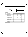
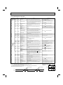
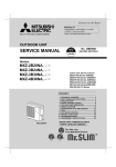
SPLIT-TYPE, HEAT PUMP AIR CONDITIONERS
OUTDOOR UNIT
SERVICE MANUAL
HFC
utilized
No. OB444
REVISED EDITION-D
R410A
Inverter-controlled multi system type
Models
MXZ-2A20NA
MXZ-2A20NA MXZ-2A20NA MXZ-3A30NA
MXZ-3A30NA MXZ-4A36NA
1
2
1
Indoor unit service manual
MSZ-A·NA Series (OB450)
CONTENTS
MXZ-2A20NA
MXZ-2A20NA NOTE:
• This service manual describes technical
data of the outdoor units.
• RoHS compliant products have <G> mark
on the spec name plate.
For servicing of RoHS compliant products,
refer to the RoHS Parts List.
1. TECHNICAL CHANGES· ·································· 2
2. PART NAMES AND FUNCTIONS ····················· 6
3. INDOOR UNITS COMBINATION ······················ 7
4. SPECIFICATION ·············································· 18
5. OUTLINES AND DIMENSIONS ······················ 21
6. WIRING DIAGRAM·········································· 26
7. REFRIGERANT SYSTEM DIAGRAM ············· 32
8. DATA ································································ 38
9. ACTUATOR CONTROL··································· 54
10. SERVICE FUNCTIONS···································· 54
11. TROUBLESHOOTING ····································· 56
12. DISASSEMBLY INSTRUCTIONS ···················· 74
13. PARTS LIST····················································· 86
14. RoHS PARTS LIST ·········································· 94
15. OPTIONAL PARTS ·········································110
1
The Slim Line.
From Mitsubishi Electric.
TM
9700058
33223
Revision A:
• RoHS PARTS LIST has been added.
Revision B:
• MXZ-2A20NA -
1
and MXZ-3A30NA -
have been added.
1
Revision C:
• MXZ-4A36NA has been added.
Revision D:
• MXZ-2A20NA -
1
2
has been added.
TECHNICAL CHANGES
MXZ-2A20NA
New model
MXZ-30TN2
MXZ-3A30NA
1. Combinations of connectable indoor units have been increased.
2. Capacity class of connectable indoor units have been made larger.
3. Compressor has been changed. (THV247FBA TNB220FMCH)
4. Outdoor fan motor has been changed. (RA6N60-AA RC0J60-AB)
5. Refrigerant has been changed. (R22 R410A)
6. Refrigerant system diagram has been changed.
• 1 of 2 high pressure switch has been removed.
• Accumulator has been removed.
• Receiver has been added.
7. Communication system has been changed.
8. Power supply way has been changed (change to supply to outdoor unit).
9. Evaporation temperature thermistor has been added.
10. Ambient temperature thermistor has been added.
MXZ-2A20NA
1.
2.
3.
4.
5.
MXZ-2A20NA -
1
Compressor has been changed. (SNB130FPDH1 SNB130FQBH1)
Gas pipe temperature thermistor has been removed.
Pre-heat control has been added.
Electronic control P.C. board has been changed.
Power board has been changed.
MXZ-3A30NA
MXZ-3A30NA -
1
1. Ball valve has been changed to stop valve.
2. Gas pipe temperature thermistor has been removed.
3. Pre-heat control has been added.
4. Auto line correcting function has been added.
5. Noise filter P.C. board has been changed.
6. Electronic control P.C. board has been changed.
7. Weight has been changed. (158lb. 148lb.)
MXZ-4A36NA
New model
MXZ-2A20NA 1.
2.
3.
4.
1
MXZ-2A20NA -
2
Electronic control P.C. board has been changed.
Noise filter P.C. board has been changed.
Ball valve has been changed to stop valve.
Sub panel has been added.
2
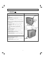
INFORMATION FOR THE AIR CONDITIONER WITH R410A REFRIGERANT
oil
Refrigeration
Refrigerant
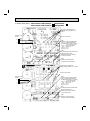
• This room air conditioner adopts HFC refrigerant (R410A) which never destroys the ozone layer.
• Pay particular attention to the following points, though the basic installation procedure is same as that for R22 air
conditioners.
As R410A has working pressure approximate 1.6 times as high as that of R22, some special tools and piping parts/
materials are required. Refer to the table below.
Take sufficient care not to allow water and other contaminations to enter the R410A refrigerant during storage and
installation, since it is more susceptible to contaminations than R22.
For refrigerant piping, use clean, pressure-proof parts/materials specifically designed for R410A. (Refer to 2. Refrigerant
piping.)
Composition change may occur in R410A since it is a mixed refrigerant. When charging, charge liquid refrigerant to prevent
composition change.
Refrigerant
Composition (Ratio)
Refrigerant handling
Chlorine
Safety group (ASHRAE)
Molecular weight
Boiling point (-˚F)
Steam pressure [77-˚F](PSIG)
Saturated steam density [77˚F](lb/ft3)
Combustibility
ODP 1
GWP 2
Refrigerant charge method
Additional charge on leakage
Kind
Color
Smell
1: Ozone Depletion Potential
2: Global Warming Potential
New refrigerant
R410A
HFC-32: HFC-125 (50%:50%)
Pseudo-azeotropic refrigerant
Not included
A1/A1
72.6
-60.5
225.82
3.995
Non combustible
0
1730
From liquid phase in cylinder
Possible
Incompatible oil
Non
Non
: based on CFC-11
: based on CO2
3
Previous refrigerant
R22
R22 (100%)
Single refrigerant
Included
A1
86.5
-41.4
136.34
2.772
Non combustible
0.055
1700
Gas phase
Possible
Compatible oil
Light yellow
Non
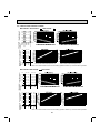
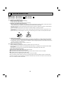
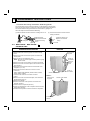
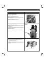
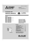
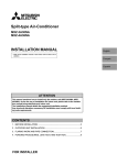
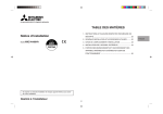
Compressor
New Specification
Current Specification
The incompatible refrigeration oil easily separates from
Since refrigerant and refrigeration oil are compatible,
refrigerant and is in the upper layer inside the suction muffler. refrigeration oil goes back to the compressor through the
Raising position of the oil back hole enables to back the
lower position oil back hole.
refrigeration oil of the upper layer to flow back to the
compressor.
Suction muffler
Suction muffler
Oil back hole
Compressor
Compressor
Refrigeration oil
Oil back hole
Refrigerant
Refrigeration oil /Refrigerant
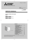
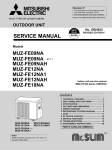
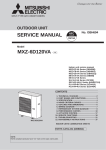
Conversion chart of refrigerant temperature and pressure
(PSIG)
580
Saturated liquid pressure
508
R410A
435
R22
363
290
218
145
73
0
-73
-22
-4
14
32
50
68
86
104 122 140
(°F)
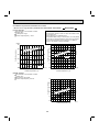
1. Tools dedicated for the air conditioner with R410A refrigerant
The following tools are required for R410A refrigerant. Some R22 tools can be substituted for R410A tools.
R410A tools
Description
Can R22 tools be used?
R410A has high pressures beyond the measurement range of existing
gauges.
Gauge manifold
No
Charge hose
No
Hose material has been changed to improve the pressure resistance.
Gas leak detector
No
Dedicated for HFC refrigerant.
Yes
1/4in. and 3/8in.
Torque wrench
No
1/2in. and 5/8in.
Flare tool
Yes
Clamp bar hole has been enlarged to reinforce the spring strength in the tool.
Flare gauge
Vacuum pump
adapter
Electronic scale for
refrigerant charging
New
Provided for flaring work (to be used with R22 flare tool).
Provided to prevent the back flow of oil. This adapter enables you to use
vacuum pumps.
It is difficult to measure R410A with a charging cylinder because the
refrigerant bubbles due to high pressure and high-speed vaporization.
New
New
No : Not Substitutable for R410A
Yes : Substitutable for R410A
4
2. Refrigerant piping
Specifications
Use the copper or copper-alloy seamless pipes for refrigerant that meet the following specifications.
1/4
Wall thickness
(inch)
0.0315
3/8
0.0315
Heat resisting foam plastic
1/2
0.0315
Specific gravity 0.045 Thickness 0.315 inch
5/8
0.0394
Outside diameter
(inch)
Insulation material
Flaring work and flare nut
Flaring work for R410A pipe differs from that for R22 pipe.
For details of flaring work, refer to installation manual “FLARING WORK”.
Dimension of flare nut
(mm) [inch]
Pipe diameter
(inch)
1/4
R410A
R22
17 [11/16]
17 [11/16]
3/8
22 [7/8]
22 [7/8]
1/2
26 [1-1/32]
24 [15/16]
5/8
29 [1-5/32]
27 [1-1/16]
3. Refrigeration oil
Apply the special refrigeration oil (accessories: packed with indoor unit) to the flare and the union seat surfaces.
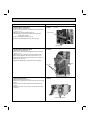
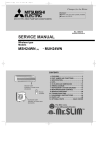
4. Air purge
• Do not discharge the refrigerant into the atmosphere.
Take care not to discharge refrigerant into the atmosphere during installation, reinstallation, or repairs to the refrigerant
circuit.
• Use the vacuum pump for air purging for the purpose of environmental protection.
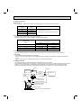
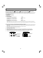
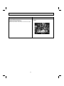
5. Additional charge
For additional charging, charge the refrigerant from liquid phase of the gas cylinder.
If the refrigerant is charged from the gas phase, composition change may occur in the refrigerant inside the cylinder and the
outdoor unit. In this case, ability of the refrigeration cycle decreases or normal operation can be impossible. However,
charging the liquid refrigerant all at once may cause the compressor to be locked. Thus, charge the refrigerant slowly.
Union
Stop valve
Indoor unit
Liquid pipe
Gas pipe
Refrigerant gas
cylinder
operating valve
Outdoor unit
Service port
Gauge manifold
valve (for R410A)
Charge hose (for R410A)
Refrigerant gas cylinder
for R410A with siphon
Refrigerant (liquid)
Electronic scale for refrigerant charging
5
2
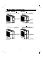
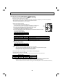
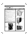
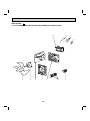
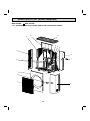
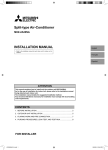
PART NAMES AND FUNCTIONS
MXZ-2A20NA
MXZ-2A20NA -
MXZ-2A20NA -
1
2
Air inlet
(Back and side)
Air inlet
(Back and side)
Air outlet
Air outlet
Drain outlet
Drain outlet
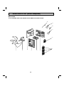
MXZ-3A30NA -
MXZ-3A30NA
Air inlet
(Back and side)
1
MXZ-4A36NA
Air inlet
(Back and side)
Air outlet
Air outlet
Drain outlet
Drain outlet
6
3
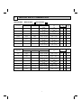
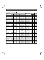
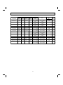
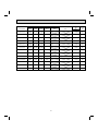
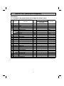
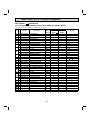
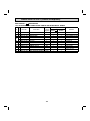
INDOOR UNITS COMBINATION
MXZ-2A20NA
MXZ-2A20NA -
1
MXZ-2A20NA -
2
Cooling capacity (BTU/h)
Indoor units
combination
Unit A
Unit B
09
9,000
–
12
12,000
–
15
15,000
–
09+09
9,000
9,000
09+12
8,500
11,500
09+15
7,500
12,500
12+12
10,000
10,000
Total
Power consumption
(W)
9,000
(5,400 ~ 9,000)
12,000
(5,400 ~ 12,000)
15,000
(5,400 ~ 15,000)
18,000
(7,800 ~ 18,000)
20,000
(7,800 ~ 20,000)
20,000
(7,800 ~ 20,000)
20,000
(7,800 ~ 20,000)
730
(490 ~ 730)
990
( 490 ~ 990)
1,540
(490 ~ 1,540)
1,740
(630 ~ 1,740)
2,150
(630 ~ 2,150)
2,150
(630 ~ 2,150)
2,150
(630 ~ 2,150)
Heating capacity (BTU/h)
Indoor units
combination
Unit A
Unit B
09
10,900
–
12
13,600
–
15
18,000
–
09+09
10,900
10,900
09+12
9,500
12,500
09+15
8,250
13,750
12+12
11,000
11,000
Total
Power consumption
(W)
10,900
(5,200 ~ 15,400)
13,600
(5,200 ~ 16,400)
18,000
(5,200 ~ 21,100)
21,800
(8,500 ~ 21,800)
22,000
(8,500 ~ 22,000)
22,000
(8,500 ~ 22,000)
22,000
(8,500 ~ 22,000)
940
(480 ~ 1,430)
1,180
(480 ~1,460)
1,720
(480 ~ 2,100)
1,820
(520 ~ 1,820)
1,780
(520 ~ 1,780)
1,780
(520 ~ 1,780)
1,780
(520 ~ 1,780)
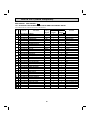
7
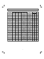
Current
(A)
208 V 230 V
Power
factor
(%)
3.69
3.34
95
5.01
4.53
95
7.79
7.05
95
8.62
7.80
97
10.66
9.64
97
10.66
9.64
97
10.66
9.64
97
Current
(A)
208 V 230 V
Power
factor
(%)
4.76
4.30
95
5.97
5.40
95
8.70
7.87
95
9.02
8.16
97
8.82
7.98
97
8.82
7.98
97
8.82
7.98
97
MXZ-3A30NA MXZ-3A30NA -
1
Cooling capacity (BTU/h)
Indoor units
combination
Unit A
Unit B
Unit C
09
9,000
–
–
12
12,000
–
–
15
15,000
–
–
17
16,200
–
–
24
22,000
–
–
09+09
9,000
9,000
–
09+12
9,000
12,000
–
09+15
9,000
15,000
–
09+17
9,000
16,200
–
09+24
7,600
20,400
–
12+12
12,000
12,000
–
12+15
11,500
14,500
–
12+17
10,800
15,200
–
15+15
13,000
13,000
–
15+17
12,200
13,800
–
17+17
13,000
13,000
–
09+09+09
9,000
9,000
9,000
09+09+12
8,500
8,500
11,400
09+09+15
7,750
7,750
12,900
09+09+17
7,300
7,300
13,800
Total
Power consumption
(W)
9,000
(7,200 ~ 9,000)
12,000
(7,200 ~ 12,000)
15,000
(7,200 ~ 15,000)
16,200
(7,200 ~ 16,200)
22,000
(7,200 ~ 22,000)
18,000
(12,000 ~ 18,000)
21,000
(12,000 ~ 21,000)
24,000
(12,000 ~ 24,000)
25,200
(12,000 ~ 25,200)
28,000
(12,000 ~ 28,000)
24,000
(12,000 ~ 24,000)
26,000
(12,000 ~ 26,000)
26,000
(12,000 ~ 26,000)
26,000
(12,000 ~ 26,000)
26,000
(12,000 ~ 26,000)
26,000
(12,000 ~ 26,000)
27,000
(12,600 ~ 27,000)
28,400
(12,600 ~ 28,400)
28,400
(12,600 ~ 28,400)
28,400
(12,600 ~ 28,400)
800
(650 ~ 800)
1,000
(650 ~ 1,000)
1,320
(650 ~ 1,320)
1,480
(650 ~ 1,480)
2,220
(650 ~ 2,200)
1,800
(920 ~ 1,800)
2,000
(920 ~ 2,000)
2,500
(920 ~ 2,500)
2,700
(920 ~ 2,700)
3,200
(920 ~ 3,200)
2,500
(920 ~ 2,500)
2,800
(920 ~ 2,800)
2,800
(920 ~ 2,800)
2,800
(920 ~ 2,800)
2,800
(920 ~ 2,800)
2,800
(920 ~ 2,800)
2,860
(1,000 ~ 2,850)
3,250
(1,000 ~ 3,250)
3,250
(1,000 ~ 3,250)
3,250
(1,000 ~ 3,250)
8
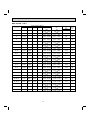
Current
(A)
208 V 230 V
Power
factor
(%)
4.05
3.66
95
5.06
4.58
95
6.68
6.04
95
7.49
6.77
95
11.13
10.07
95
8.92
8.07
97
9.91
8.96
97
12.39
11.21
97
13.38 12.10
97
15.86 14.34
97
12.39
11.21
97
13.88 12.55
97
13.88 12.55
97
13.88 12.55
97
13.88 12.55
97
13.88 12.55
97
14.18 12.82
97
16.11
14.57
97
16.11
14.57
97
16.11
14.57
97
Heating capacity (BTU/h)
Indoor units
combination
Unit A
Unit B
Unit C
09
10,900
–
–
12
13,600
–
–
15
18,000
–
–
17
20,100
–
–
24
23,200
–
–
09+09
10,900
10,900
–
09+12
10,900
13,600
–
09+15
10,100
16,900
–
09+17
9,300
17,700
–
09+24
7,300
19,700
–
12+12
13,500
13,500
–
12+15
12,000
15,000
–
12+17
11,200
15,800
–
15+15
13,500
13,500
–
15+17
12,700
14,300
–
17+17
13,500
13,500
–
09+09+09
9,500
9,500
9,500
09+09+12
8,600
8,600
11,400
09+09+15
7,800
7,800
13,000
09+09+17
7,350
7,350
13,900
Total
Power consumption
(W)
10,900
(8,600 ~ 15,400)
13,600
(8,600 ~ 16,400)
18,000
(8,600 ~ 21,100)
20,100
(8,600 ~ 21,500)
23,200
(8,600 ~ 27,800)
21,800
(11,000 ~ 31,000)
24,500
(11,000 ~ 33,000)
27,000
(11,000 ~ 35,000)
27,000
(11,000 ~ 35,000)
27,000
(11,000 ~ 35,000)
27,000
(11,000 ~ 35,000)
27,000
(11,000 ~ 35,000)
27,000
(11,000 ~ 35,000)
27,000
(11,000 ~ 35,000)
27,000
(11,000 ~ 35,000)
27,000
(11,000 ~ 35,000)
28,500
(11,400 ~ 36,000)
28,600
(11,400 ~ 36,000)
28,600
(11,400 ~ 36,000)
28,600
(11,400 ~ 36,000)
1,100
(780 ~1,520)
1,380
(780 ~ 1,600)
1,940
(780 ~ 2,280)
2,240
(780 ~ 2,300)
2,520
(780 ~ 3,000)
1,700
(740 ~2,560)
1,980
(740 ~ 2,800)
2,200
(740 ~ 2,920)
2,200
(740 ~ 2,920)
1,980
(740 ~ 2,740)
2,200
(740 ~ 2,920)
2,160
(740 ~ 2,860)
2,140
(740 ~ 2,860)
2,120
(740 ~ 2,800)
2,110
(740 ~ 2,800)
2,100
(740 ~ 2,800)
2,180
(740 ~ 2,880)
2,180
(740 ~ 2,880)
2,180
(740 ~ 2,880)
2,180
(740 ~ 2,880)
9
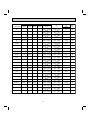
Current
(A)
208 V 230 V
Power
factor
(%)
5.57
5.03
95
6.98
6.32
95
9.82
8.88
95
11.34
10.25
95
12.75
11.53
95
8.43
7.62
97
9.81
8.87
97
10.90
9.86
97
10.90
9.86
97
9.81
8.87
97
10.90
9.86
97
10.71
9.68
97
10.61
9.59
97
10.51
9.50
97
10.46
9.46
97
10.41
9.41
97
10.80
9.77
97
10.80
9.77
97
10.80
9.77
97
10.80
9.77
97
MXZ-4A36NA 208 V
Cooling capacity (BTU/h)
Indoor units
combination
Unit A
Unit B
Unit C
Unit D
09
9,000
–
–
–
12
12,000
–
–
–
15
15,000
–
–
–
17
16,200
–
–
–
24
22,000
–
–
–
09+09
9,000
9,000
–
–
09+12
9,000
12,000
–
–
09+15
9,000
15,000
–
–
09+17
9,000
16,200
–
–
09+24
7,600
20,400
–
–
12+12
12,000
12,000
–
–
12+15
11,500
14,500
–
–
12+17
10,800
15,200
–
–
15+15
13,000
13,000
–
–
15+17
12,200
13,800
–
–
17+17
13,000
13,000
–
–
09+09+09
9,000
9,000
9,000
–
09+09+12
9,000
9,000
12,000
–
09+09+15
8,800
8,800
14,500
–
09+09+17
8,200
8,200
15,700
–
09+09+24
6,900
6,900
18,300
–
09+12+12
8,700
11,700
11,700
–
Total
Power consumption
(W)
9,000
(7,200 ~ 9,000)
12,000
(7,200 ~ 12,000)
15,000
(7,200 ~ 15,000)
16,200
(7,200 ~ 16,200)
22,000
(7,200 ~ 22,000)
18,000
(12,000 ~ 18,000)
21,000
(12,000 ~ 21,000)
24,000
(12,000 ~ 24,000)
25,200
(12,000 ~ 25,200)
28,000
(12,000 ~ 28,000)
24,000
(12,000 ~ 24,000)
26,000
(12,000 ~ 26,000)
26,000
(12,000 ~ 26,000)
26,000
(12,000 ~ 26,000)
26,000
(12,000 ~ 26,000)
26,000
(12,000 ~ 26,000)
27,000
(12,600 ~ 27,000)
30,000
(12,600 ~ 30,000)
32,100
(12,600 ~ 32,100)
32,100
(12,600 ~ 32,100)
32,100
(12,600 ~ 32,100)
32,100
(12,600 ~ 32,100)
800
(650 ~ 800)
1,000
(650 ~ 1,000)
1,320
(650 ~ 1,320)
1,480
(650 ~ 1,480)
2,200
(650 ~ 2,200)
1,800
(920 ~ 1,800)
2,000
(920 ~ 2,000)
2,500
(920 ~ 2,500)
2,700
(920 ~ 2,700)
3,200
(920 ~ 3,200)
2,500
(920 ~ 2,500)
2,800
(920 ~ 2,800)
2,800
(920 ~ 2,800)
2,800
(920 ~ 2,800)
2,800
(920 ~ 2,800)
2,800
(920 ~ 2,800)
2,860
(1,000 ~ 2,850)
3,270
(1,000 ~ 3,270)
3,500
(1,000 ~ 3,500)
3,500
(1,000 ~ 3,500)
3,500
(1,000 ~ 3,500)
3,500
(1,000 ~ 3,500)
10
Current
(A)
208 V
Power
factor
(%)
4.05
95
5.06
95
6.68
95
7.49
95
11.13
95
8.92
97
9.91
97
12.39
97
13.38
97
15.86
97
12.39
97
13.88
97
13.88
97
13.88
97
13.88
97
13.88
97
14.18
97
16.21
97
17.35
97
17.35
97
17.35
97
17.35
97
Cooling capacity (BTU/h)
Indoor units
combination
Unit A
Unit B
Unit C
09+12+15
8,000
10,700
13,400
09+12+17
7,600
10,100
14,400
09+15+15
7,500
12,300
12,300
09+15+17
7,100
11,700
13,300
09+17+17
6,700
12,700
12,700
12+12+12
10,700
10,700
10,700
12+12+15
9,900
9,900
12,300
12+12+17
9,400
9,400
13,300
12+15+15
9,100
11,500
11,500
09+09+09+09
9,000
9,000
9,000
09+09+09+12
8,300
8,300
8,300
09+09+09+15
7,700
7,700
7,700
09+09+12+12
7,700
7,700
10,300
Total
Unit D
32,100
(12,600 ~ 32,100)
32,100
–
(12,600 ~ 32,100)
32,100
–
(12,600 ~ 32,100)
32,100
–
(12,600 ~ 32,100)
32,100
–
(12,600 ~ 32,100)
32,100
–
(12,600 ~ 32,100)
32,100
–
(12,600 ~ 32,100)
32,100
–
(12,600 ~ 32,100)
32,100
–
(12,600 ~ 32,100)
36,000
9,000
(12,600 ~ 36,400)
36,000
11,100
(12,600 ~ 36,400)
36,000
12,900
(12,600 ~ 36,400)
36,000
10,300
(12,600 ~ 36,400)
–
11
Power consumption
(W)
3,500
(1,000 ~ 3,500)
3,500
(1,000 ~ 3,500)
3,500
(1,000 ~ 3,500)
3,500
(1,000 ~ 3,500)
3,500
(1,000 ~ 3,500)
3,500
(1,000 ~ 3,500)
3,500
(1,000 ~ 3,500)
3,500
(1,000 ~ 3,500)
3,500
(1,000 ~ 3,500)
3,820
(1,000 ~ 3,900)
3,820
(1,000 ~ 3,900)
3,820
(1,000 ~ 3,900)
3,820
(1,000 ~ 3,900)
Current
(A)
208 V
Power
factor
(%)
17.35
97
17.35
97
17.35
97
17.35
97
17.35
97
17.35
97
17.35
97
17.35
97
17.35
97
18.55
99
18.55
99
18.55
99
18.55
99
Heating capacity (BTU/h)
Indoor units
combination
Unit A
Unit B
Unit C
Unit D
09
10,900
–
–
–
12
13,600
–
–
–
15
18,000
–
–
–
17
20,100
–
–
–
24
23,200
–
–
–
09+09
10,900
10,900
–
–
09+12
10,900
13,600
–
–
09+15
10,100
16,900
–
–
09+17
9,300
17,700
–
–
09+24
7,300
19,700
–
–
12+12
13,500
13,500
–
–
12+15
12,000
15,000
–
–
12+17
11,200
15,800
–
–
15+15
13,500
13,500
–
–
15+17
12,700
14,300
–
–
17+17
13,500
13,500
–
–
09+09+09
10,800
10,800
10,800
–
09+09+12
10,000
10,000
12,400
–
09+09+15
8,900
8,900
14,600
–
09+09+17
8,400
8,400
15,600
–
09+09+24
7,800
7,800
16,800
–
09+12+12
9,400
11,500
11,500
–
09+12+15
8,300
10,400
13,700
–
Total
Power consumption
(W)
10,900
(8,600 ~ 15,400)
13,600
(8,600 ~ 16,400)
18,000
(8,600 ~ 21,100)
20,100
(8,600 ~ 21,500)
23,200
(8,600 ~ 27,800)
21,800
(11,000 ~ 31,000)
24,500
(11,000 ~ 33,000)
27,000
(11,000 ~ 35,000)
27,000
(11,000 ~ 35,000)
27,000
(11,000 ~ 35,000)
27,000
(11,000 ~ 35,000)
27,000
(11,000 ~ 35,000)
27,000
(11,000 ~ 35,000)
27,000
(11,000 ~ 35,000)
27,000
(11,000 ~ 35,000)
27,000
(11,000 ~ 35,000)
32,400
(11,400 ~ 36,000)
32,400
(11,400 ~ 36,000)
32,400
(11,400 ~ 36,000)
32,400
(11,400 ~ 36,000)
32,400
(11,400 ~ 36,000)
32,400
(11,400 ~ 36,000)
32,400
(11,400 ~ 36,000)
1,100
(780 ~1,520)
1,380
(780 ~ 1,600)
1,940
(780 ~ 2,280)
2,240
(780 ~ 2,300)
2,520
(780 ~ 3,000)
1,700
(740 ~2,560)
1,980
(740 ~ 2,800)
2,200
(740 ~ 2,920)
2,200
(740 ~ 2,920)
1,980
(740 ~ 2,740)
2,200
(740 ~ 2,920)
2,160
(740 ~ 2,860)
2,140
(740 ~ 2,860)
2,120
(740 ~ 2,800)
2,110
(740 ~ 2,800)
2,100
(740 ~ 2,800)
2,700
(740 ~ 2,880)
2,700
(740 ~ 2,880)
2,700
(740 ~ 2,880)
2,700
(740 ~ 2,880)
2,700
(740 ~ 2,880)
2,700
(740 ~ 2,880)
2,700
(740 ~ 2,880)
12
Current
(A)
208 V
Power
factor
(%)
5.57
95
6.98
95
9.82
95
11.34
95
12.75
95
8.43
97
9.81
97
10.90
97
10.90
97
9.81
97
10.90
97
10.71
97
10.61
97
10.51
97
10.46
97
10.41
97
13.38
97
13.38
97
13.38
97
13.38
97
13.38
97
13.38
97
13.38
97
Heating capacity (BTU/h)
Indoor units
combination
Unit A
Unit B
Unit C
Unit D
09+12+17
7,900
9,900
14,600
–
09+15+15
7,600
12,400
12,400
–
09+15+17
7,200
11,900
13,300
–
09+17+17
7,000
12,700
12,700
–
12+12+12
10,800
10,800
10,800
–
12+12+15
9,700
9,700
13,000
–
12+12+17
9,300
9,300
13,800
–
12+15+15
9,000
11,700
11,700
–
09+09+09+09
9,000
9,000
9,000
9,000
09+09+09+12
8,300
8,300
8,300
11,100
09+09+09+15
7,700
7,700
7,700
12,900
09+09+12+12
7,700
7,700
10,300
10,300
Total
Power consumption
(W)
32,400
(11,400 ~ 36,000)
32,400
(11,400 ~ 36,000)
32,400
(11,400 ~ 36,000)
32,400
(11,400 ~ 36,000)
32,400
(11,400 ~ 36,000)
32,400
(11,400 ~ 36,000)
32,400
(11,400 ~ 36,000)
32,400
(11,400 ~ 36,000)
36,000
(11,400 ~ 41,200)
36,000
(11,400 ~ 41,200)
36,000
(11,400 ~ 41,200)
36,000
(11,400 ~ 41,200)
2,700
(740 ~ 2,880)
2,700
(740 ~ 2,880)
2,700
(740 ~ 2,880)
2,700
(740 ~ 2,880)
2,700
(740 ~ 2,880)
2,700
(740 ~ 2,880)
2,700
(740 ~ 2,880)
2,700
(740 ~ 2,880)
3,100
(740 ~ 4,000)
3,100
(740 ~ 4,000)
3,100
(740 ~ 4,000)
3,100
(740 ~ 4,000)
13
Current
(A)
208 V
Power
factor
(%)
13.38
97
13.38
97
13.38
97
13.38
97
13.38
97
13.38
97
13.38
97
13.38
97
15.05
99
15.05
99
15.05
99
15.05
99
MXZ-4A36NA 230 V
Cooling capacity (BTU/h)
Indoor units
combination
Unit A
Unit B
Unit C
Unit D
09
9,000
–
–
–
12
12,000
–
–
–
15
15,000
–
–
–
17
16,200
–
–
–
24
22,000
–
–
–
09+09
9,000
9,000
–
–
09+12
9,000
12,000
–
–
09+15
9,000
15,000
–
–
09+17
9,000
16,200
–
–
09+24
7,600
20,400
–
–
12+12
12,000
12,000
–
–
12+15
11,500
14,500
–
–
12+17
10,800
15,200
–
–
15+15
13,000
13,000
–
–
15+17
12,200
13,800
–
–
17+17
13,000
13,000
–
–
09+09+09
9,000
9,000
9,000
–
09+09+12
9,000
9,000
12,000
–
09+09+15
8,800
8,800
14,500
–
09+09+17
8,200
8,200
15,700
–
09+09+24
6,900
6,900
18,300
–
09+12+12
8,700
11,700
11,700
–
Total
Power consumption
(W)
9,000
(7,200 ~ 9,000)
12,000
(7,200 ~ 12,000)
15,000
(7,200 ~ 15,000)
16,200
(7,200 ~ 16,200)
22,000
(7,200 ~ 22,000)
18,000
(12,000 ~ 18,000)
21,000
(12,000 ~ 21,000)
24,000
(12,000 ~ 24,000)
25,200
(12,000 ~ 25,200)
28,000
(12,000 ~ 28,000)
24,000
(12,000 ~ 24,000)
26,000
(12,000 ~ 26,000)
26,000
(12,000 ~ 26,000)
26,000
(12,000 ~ 26,000)
26,000
(12,000 ~ 26,000)
26,000
(12,000 ~ 26,000)
27,000
(12,600 ~ 27,000)
30,000
(12,600 ~ 30,000)
32,100
(12,600 ~ 32,100)
32,100
(12,600 ~ 32,100)
32,100
(12,600 ~ 32,100)
32,100
(12,600 ~ 32,100)
800
(650 ~ 800)
1,000
(650 ~ 1,000)
1,320
(650 ~ 1,320)
1,480
(650 ~ 1,480)
2,200
(650 ~ 2,200)
1,800
(920 ~ 1,800)
2,000
(920 ~ 2,000)
2,500
(920 ~ 2,500)
2,700
(920 ~ 2,700)
3,200
(920 ~ 3,200)
2,500
(920 ~ 2,500)
2,800
(920 ~ 2,800)
2,800
(920 ~ 2,800)
2,800
(920 ~ 2,800)
2,800
(920 ~ 2,800)
2,800
(920 ~ 2,800)
2,860
(1,000 ~ 2,850)
3,270
(1,000 ~ 3,270)
3,500
(1,000 ~ 3,500)
3,500
(1,000 ~ 3,500)
3,500
(1,000 ~ 3,500)
3,500
(1,000 ~ 3,500)
14
Current
(A)
230 V
Power
factor
(%)
3.66
95
4.58
95
6.04
95
6.77
95
10.07
95
8.07
97
8.96
97
11.21
97
12.10
97
14.34
97
11.21
97
12.55
97
12.55
97
12.55
97
12.55
97
12.55
97
12.82
97
14.66
97
15.69
97
15.69
97
15.69
97
15.69
97
Cooling capacity (BTU/h)
Indoor units
combination
Unit A
Unit B
Unit C
09+12+15
8,000
10,700
13,400
09+12+17
7,600
10,100
14,400
09+15+15
7,500
12,300
12,300
09+15+17
7,100
11,700
13,300
09+17+17
6,700
12,700
12,700
12+12+12
10,700
10,700
10,700
12+12+15
9,900
9,900
12,300
12+12+17
9,400
9,400
13,300
12+15+15
9,100
11,500
11,500
09+09+09+09
9,000
9,000
9,000
09+09+09+12
8,300
8,300
8,300
09+09+09+15
7,700
7,700
7,700
09+09+12+12
7,700
7,700
10,300
Total
Unit D
32,100
(12,600 ~ 32,100)
32,100
–
(12,600 ~ 32,100)
32,100
–
(12,600 ~ 32,100)
32,100
–
(12,600 ~ 32,100)
32,100
–
(12,600 ~ 32,100)
32,100
–
(12,600 ~ 32,100)
32,100
–
(12,600 ~ 32,100)
32,100
–
(12,600 ~ 32,100)
32,100
–
(12,600 ~ 32,100)
36,000
9,000
(12,600 ~ 36,400)
36,000
11,100
(12,600 ~ 36,400)
36,000
12,900
(12,600 ~ 36,400)
36,000
10,300
(12,600 ~ 36,400)
–
15
Power consumption
(W)
3,500
(1,000 ~ 3,500)
3,500
(1,000 ~ 3,500)
3,500
(1,000 ~ 3,500)
3,500
(1,000 ~ 3,500)
3,500
(1,000 ~ 3,500)
3,500
(1,000 ~ 3,500)
3,500
(1,000 ~ 3,500)
3,500
(1,000 ~ 3,500)
3,500
(1,000 ~ 3,500)
3,820
(1,000 ~ 3,900)
3,820
(1,000 ~ 3,900)
3,820
(1,000 ~ 3,900)
3,820
(1,000 ~ 3,900)
Current
(A)
230 V
Power
factor
(%)
15.69
97
15.69
97
15.69
97
15.69
97
15.69
97
15.69
97
15.69
97
15.69
97
15.69
97
16.78
99
16.78
99
16.78
99
16.78
99
Heating capacity (BTU/h)
Indoor units
combination
Unit A
Unit B
Unit C
Unit D
09
10,900
–
–
–
12
13,600
–
–
–
15
18,000
–
–
–
17
20,100
–
–
–
24
23,200
–
–
–
09+09
10,900
10,900
–
–
09+12
10,900
13,600
–
–
09+15
10,100
16,900
–
–
09+17
9,300
17,700
–
–
09+24
7,300
19,700
–
–
12+12
13,500
13,500
–
–
12+15
12,000
15,000
–
–
12+17
11,200
15,800
–
–
15+15
13,500
13,500
–
–
15+17
12,700
14,300
–
–
17+17
13,500
13,500
–
–
09+09+09
10,800
10,800
10,800
–
09+09+12
10,000
10,000
12,400
–
09+09+15
8,900
8,900
14,600
–
09+09+17
8,400
8,400
15,600
–
09+09+24
7,800
7,800
16,800
–
09+12+12
9,400
11,500
11,500
–
09+12+15
8,300
10,400
13,700
–
Total
Power consumption
(W)
10,900
(8,600 ~ 15,400)
13,600
(8,600 ~ 16,400)
18,000
(8,600 ~ 21,100)
20,100
(8,600 ~ 21,500)
23,200
(8,600 ~ 27,800)
21,800
(11,000 ~ 31,000)
24,500
(11,000 ~ 33,000)
27,000
(11,000 ~ 35,000)
27,000
(11,000 ~ 35,000)
27,000
(11,000 ~ 35,000)
27,000
(11,000 ~ 35,000)
27,000
(11,000 ~ 35,000)
27,000
(11,000 ~ 35,000)
27,000
(11,000 ~ 35,000)
27,000
(11,000 ~ 35,000)
27,000
(11,000 ~ 35,000)
32,400
(11,400 ~ 36,000)
32,400
(11,400 ~ 36,000)
32,400
(11,400 ~ 36,000)
32,400
(11,400 ~ 36,000)
32,400
(11,400 ~ 36,000)
32,400
(11,400 ~ 36,000)
32,400
(11,400 ~ 36,000)
1,100
(780 ~1,520)
1,380
(780 ~ 1,600)
1,940
(780 ~ 2,280)
2,240
(780 ~ 2,300)
2,520
(780 ~ 3,000)
1,700
(740 ~2,560)
1,980
(740 ~ 2,800)
2,200
(740 ~ 2,920)
2,200
(740 ~ 2,920)
1,980
(740 ~ 2,740)
2,200
(740 ~ 2,920)
2,160
(740 ~ 2,860)
2,140
(740 ~ 2,860)
2,120
(740 ~ 2,800)
2,110
(740 ~ 2,800)
2,100
(740 ~ 2,800)
2,700
(740 ~ 2,880)
2,700
(740 ~ 2,880)
2,700
(740 ~ 2,880)
2,700
(740 ~ 2,880)
2,700
(740 ~ 2,880)
2,700
(740 ~ 2,880)
2,700
(740 ~ 2,880)
16
Current
(A)
230 V
Power
factor
(%)
5.03
95
6.32
95
8.88
95
10.25
95
11.53
95
7.62
97
8.87
97
9.86
97
9.86
97
8.87
97
9.86
97
9.68
97
9.59
97
9.50
97
9.46
97
9.41
97
12.10
97
12.10
97
12.10
97
12.10
97
12.10
97
12.10
97
12.10
97
Heating capacity (BTU/h)
Indoor units
combination
Unit A
Unit B
Unit C
Unit D
09+12+17
7,900
9,900
14,600
–
09+15+15
7,600
12,400
12,400
–
09+15+17
7,200
11,900
13,300
–
09+17+17
7,000
12,700
12,700
–
12+12+12
10,800
10,800
10,800
–
12+12+15
9,700
9,700
13,000
–
12+12+17
9,300
9,300
13,800
–
12+15+15
9,000
11,700
11,700
–
09+09+09+09
9,000
9,000
9,000
9,000
09+09+09+12
8,300
8,300
8,300
11,100
09+09+09+15
7,700
7,700
7,700
12,900
09+09+12+12
7,700
7,700
10,300
10,300
Total
Power consumption
(W)
32,400
(11,400 ~ 36,000)
32,400
(11,400 ~ 36,000)
32,400
(11,400 ~ 36,000)
32,400
(11,400 ~ 36,000)
32,400
(11,400 ~ 36,000)
32,400
(11,400 ~ 36,000)
32,400
(11,400 ~ 36,000)
32,400
(11,400 ~ 36,000)
36,000
(11,400 ~ 43,000)
36,000
(11,400 ~ 43,000)
36,000
(11,400 ~ 43,000)
36,000
(11,400 ~ 43,000)
2,700
(740 ~ 2,880)
2,700
(740 ~ 2,880)
2,700
(740 ~ 2,880)
2,700
(740 ~ 2,880)
2,700
(740 ~ 2,880)
2,700
(740 ~ 2,880)
2,700
(740 ~ 2,880)
2,700
(740 ~ 2,880)
3,100
(740 ~ 4,350)
3,100
(740 ~ 4,350)
3,100
(740 ~ 4,350)
3,100
(740 ~ 4,350)
17
Current
(A)
230 V
Power
factor
(%)
12.10
97
12.10
97
12.10
97
12.10
97
12.10
97
12.10
97
12.10
97
12.10
97
13.61
99
13.61
99
13.61
99
13.61
99
4
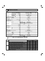
SPECIFICATION
Item
Capacity
Power
consumption
Cooling
Heating 47
Heating 17
Cooling
Heating 47
Heating 17
Cooling
Heating
Heating
EER
[SEER]
HSPF IV (V)
COP
External finish
Power supply
Max. fuse size (time delay)
Min. circuit ampacity
Fan motor
Model
Btu/h
Btu/h
Btu/h
W
W
W
V, phase, Hz
A
A
F.L.A
Model
Compressor
Winding resistance (at 68°F) Ω
R.L.A
L.R.A
Refrigerant control
Sound level
Defrost method
Dimensions
dB(A)
in.
in.
in.
lb.
W
D
H
Weight
Remote controller
Control voltage (by built-in transformer)
Refrigerant piping
Liquid
Valve size
Gas
Indoor
Connection method
Outdoor
Refrigerant charge (R410A)
in.
in.
lb.
oz.
Refrigeration oil (Model)
MXZ-2A20NA MXZ-2A20NA - 1 MXZ-2A20NA 20,000/ (7,800 ~ 20,000)
22,000/ (8,500 ~ 22,000)
14,500
2,150/ (630 ~ 2,150)
1,780/ (520 ~ 1,780)
1,500 (1,500)
9.3 [16.0]
8.5 (7.0)
3.63
Munsell 5Y 8/1
208/230, 1, 60
20
15
0.96
MXZ-2A20NA
SNB130FPDH1
MXZ-2A20NA - 1 , 2
SNB130FQBH1
U-V 0.45 V-W 0.45 W-U 0.45
MXZ-2A20NA
MXZ-2A20NA - 1 , 2 U-V 0.98 V-W 0.98 W-U 0.98
10.1
15
LEV
49/51
Reverse cycle
33-1/16
13
27-15/16
130
Wireless type
12-24 V DC
Not supplied (optional parts)
1/4
A,B: 3/8
Flared
Flared
5 lb. 15 oz.
20.3 (NEO22)
MXZ-2A20NA
23.7 (NEO22)
MXZ-2A20NA - 1 , 2
2
NOTE : Test conditions are based on ARI 210/240.
1 : Rating conditions (cooling) — Indoor : 80˚FDB, 67˚FWB, Outdoor : 95˚FDB, (75˚FWB)
(heating) — Indoor : 70˚FDB, 60˚FWB, Outdoor : 47˚FDB, 43˚FWB
2:
(heating) — Indoor : 70˚FDB, 60˚FWB, Outdoor : 17˚FDB, 15˚FWB
3:
(cooling) — Indoor : 80˚FDB, 67˚FWB, Outdoor : 82˚FDB, 65˚FWB
Unit: °F
Mode
Indoor air condition Outdoor air condition
Dry bulb Wet bulb Dry bulb Wet bulb
Test
Cooling
80
67
95
1: "A" Cooling steady state at rated compressor speed
80
67
82
3: "B-2" Cooling steady state at rated compressor speed
80
67
82
"B-1" Cooling steady state at minimum compressor speed
80
67
67
Low ambient cooling steady state at minimum compressor speed
80
67
87
Intermediate cooling steady state at intermediate compressor speed
70
60
47
1: Standard rating-heating at rated compressor speed
Heating
70
60
17
2: Low temperature heating at rated compressor speed
70
60
62
Max. temperature heating at minimum compressor speed
70
60
47
High temperature heating at minimum compressor speed
70
60
35
Frost accumulation at rated compressor speed
70
60
35
Frost accumulation at intermediate compressor speed
At intermediate compressor speed
=("Cooling rated compressor speed" - "minimum compressor speed") / 3 + "minimum compressor speed".
18
(75)
(65)
(65)
(53.5)
(69)
43
15
56.5
43
33
33
Item
Capacity
Power
consumption
Cooling
Heating 47
Heating 17
Cooling
Heating 47
Heating 17
Cooling
Heating
Heating
Model
Btu/h
Btu/h
Btu/h
W
W
W
EER
[SEER]
HSPF IV (V)
COP
External finish
Power supply
V, phase, Hz
Max. fuse size (time delay)
A
Min. circuit ampacity
A
Fan motor
F.L.A
Model
Winding resistance (at 68°F) Ω
Compressor
R.L.A
L.R.A
Refrigerant control
Sound level
dB(A)
Defrost method
W
in.
D
Dimensions
in.
H
in.
Weight
lb.
Remote controller
Control voltage (by built-in transformer)
Refrigerant piping
Liquid
Valve size
Gas
Indoor
Connection method
Outdoor
Refrigerant charge (R410A)
Refrigeration oil (Model)
MXZ-3A30NA
MXZ-3A30NA -
in.
in.
lb.
oz.
1
MXZ-3A30NA MXZ-3A30NA - 1
28,400/ (12,600 ~ 28,400)
28,600/ (11,400 ~ 36,000)
18,800
3,250/ (1,000 ~ 3,250)
2,180/ (740 ~ 2,880)
2,120
8.7 [16.0]
10.0 (7.5)
3.84
Munsell 3.0Y 7.8/1.1
208/230, 1, 60
20
15
0.93
TNB220FMCH
U-V 0.61 V-W 0.61 W-U 0.61
11
15
LEV
49/49
Reverse cycle
35-7/16
12-19/32
35-7/16
158
148
Wireless type
12-24 V DC
Not supplied (optional parts)
1/4
A: 1/2 B,C: 3/8
Flared
Flared
7 lb. 11 oz.
29.4 (NEO22)
NOTE : Test conditions are based on ARI 210/240.
1 : Rating conditions (cooling) — Indoor : 80˚FDB, 67˚FWB, Outdoor : 95˚FDB, (75˚FWB)
(heating) — Indoor : 70˚FDB, 60˚FWB, Outdoor : 47˚FDB, 43˚FWB
2:
(heating) — Indoor : 70˚FDB, 60˚FWB, Outdoor : 17˚FDB, 15˚FWB
3:
(cooling) — Indoor : 80˚FDB, 67˚FWB, Outdoor : 82˚FDB, 65˚FWB
Unit: °F
Mode
Indoor air condition Outdoor air condition
Dry bulb Wet bulb Dry bulb Wet bulb
Test
Cooling
80
67
95
1: "A" Cooling steady state at rated compressor speed
80
67
82
3: "B-2" Cooling steady state at rated compressor speed
80
67
82
"B-1" Cooling steady state at minimum compressor speed
80
67
67
Low ambient cooling steady state at minimum compressor speed
80
67
87
Intermediate cooling steady state at intermediate compressor speed
70
60
47
1: Standard rating-heating at rated compressor speed
Heating
70
60
17
2: Low temperature heating at rated compressor speed
70
60
62
Max. temperature heating at minimum compressor speed
70
60
47
High temperature heating at minimum compressor speed
70
60
35
Frost accumulation at rated compressor speed
70
60
35
Frost accumulation at intermediate compressor speed
At intermediate compressor speed
=("Cooling rated compressor speed" - "minimum compressor speed") / 3 + "minimum compressor speed".
19
(75)
(65)
(65)
(53.5)
(69)
43
15
56.5
43
33
33
Item
Capacity
Power
consumption
Cooling
Heating 47
Heating 17
Cooling
Heating 47
Heating 17
Cooling
Heating
Heating
Model
Btu/h
Btu/h
Btu/h
W
W
W
EER
[SEER]
HSPF IV (V)
COP
External finish
Power supply
V, phase, Hz
Max. fuse size (time delay)
A
Min. circuit ampacity
A
Fan motor
F.L.A
Model
Winding resistance (at 68°F) Ω
Compressor
R.L.A
L.R.A
Refrigerant control
Sound level
dB(A)
Defrost method
W
in.
D
Dimensions
in.
H
in.
Weight
lb.
Remote controller
Control voltage (by built-in transformer)
Refrigerant piping
Liquid
in.
Valve size
Gas
in.
Indoor
Connection method
Outdoor
Refrigerant charge (R410A)
lb.
Refrigeration oil (Model)
oz.
MXZ-4A36NA
36,000/ (12,600 ~ 36,400)
208 V 36,000/ (11,400 ~ 41,200)
230 V 36,000/ (11,400 ~ 43,000)
24,600
3,820/ (1,000 ~ 3,900)
230 V 3,100/ (740 ~ 4,350)
208 V 3,100/ (740 ~ 4,000)
3,340
9.4 [16.0]
8.5 (7.0)
3.40
Munsell 3.0Y 7.8/1.1
208/230, 1, 60
20
19
0.93
TNB220FMCH
U-V 0.61 V-W 0.61 W-U 0.61
14.4
15
LEV
54/57
Reverse cycle
35-7/16
12-19/32
35-7/16
150
Wireless type
12-24 V DC
Not supplied (optional parts)
1/4
A: 1/2 B,C,D: 3/8
Flared
Flared
8 lb. 13 oz.
29.4 (NEO22)
NOTE : Test conditions are based on ARI 210/240.
1 : Rating conditions (cooling) — Indoor : 80˚FDB, 67˚FWB, Outdoor : 95˚FDB, (75˚FWB)
(heating) — Indoor : 70˚FDB, 60˚FWB, Outdoor : 47˚FDB, 43˚FWB
2:
(heating) — Indoor : 70˚FDB, 60˚FWB, Outdoor : 17˚FDB, 15˚FWB
3:
(cooling) — Indoor : 80˚FDB, 67˚FWB, Outdoor : 82˚FDB, 65˚FWB
Unit: °F
Mode
Indoor air condition Outdoor air condition
Dry bulb Wet bulb Dry bulb Wet bulb
Test
Cooling
80
67
95
1: "A" Cooling steady state at rated compressor speed
80
67
82
3: "B-2" Cooling steady state at rated compressor speed
80
67
82
"B-1" Cooling steady state at minimum compressor speed
80
67
67
Low ambient cooling steady state at minimum compressor speed
80
67
87
Intermediate cooling steady state at intermediate compressor speed
70
60
47
1: Standard rating-heating at rated compressor speed
Heating
70
60
17
2: Low temperature heating at rated compressor speed
70
60
62
Max. temperature heating at minimum compressor speed
70
60
47
High temperature heating at minimum compressor speed
70
60
35
Frost accumulation at rated compressor speed
70
60
35
Frost accumulation at intermediate compressor speed
At intermediate compressor speed
=("Cooling rated compressor speed" - "minimum compressor speed") / 3 + "minimum compressor speed".
20
(75)
(65)
(65)
(53.5)
(69)
43
15
56.5
43
33
33
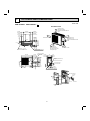
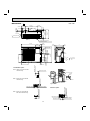
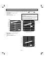
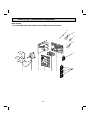
OUTLINES AND DIMENSIONS
5
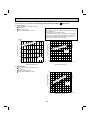
MXZ-2A20NA
MXZ-2A20NA -
Unit: inch
1
REQUIRED SPACE
6-9/16"
19-11/16"
Open as a rule
More than 19.69 in.
if the front and both sides are
open
6-21/32"
9-3/16"
11-11/32"
11/16"
11/16"
14-3/16"
Drain hole 3- 1-5/16"
Indoor and outdoor
connect wiring
1-3/16"
3- 7/8" hole
1/2"
B unit connection
A unit connection
1"
1-3/16"
12-3/4"
27-15/16"
1-3/16"
13"
More than 13.78 in.
Gas pipe
3/8"flared (both A&B unit)
2-5/8"
5-5/16"
1-25/32"
29/32"
8-5/8"
1-3/16"
15/16"
11-3/4"
Open as a rule
More than 19.69 in.
if the back, both sides
and top are open
4-13/32" x 13/16" Oval hole
(Base bolt M10)
33-1/16"
More than 3.94 in.
More than 7.87 in.
if there are obstacles to both
sides
More than 3.94 in.
15-19/32"
1-1/2"
21/32"
Air out
14-3/16"
Air in
Air in
1-7/32"
1-7/32"
2-1/2"
Liquid pipe
1/4"flared (both A&B unit)
Grounding terminal
Conduit
cover
Lock nut
21
Connector
Unit: inch
2
6-21/32"
11-11/32"
Rear Air
Intake
14-3/16"
13/16"
17/32"
Side Air Intake
3- (1-5/16") Drain Hole
11/16"
Air
Discharge
15-19/32"
9-3/16"
1-7/32"
21/32"
2-1/2"
19-11/16"
(Bolt Pitch)
6-9/16"
11/16"
MXZ-2A20NA -
4-(13/32"×13/16") Oval Hole
(Foundation Bolt M10)
33-1/16"
1-3/16"
7-7/8"
1-3/16"
13"
1/2"
3- 7/8" Punched holes
(Connecting wire hole)
2-3/8"
2-5/8"
LIQ
14-1/4"
5-5/16"
1-25/32"
14-3/16"
27-15/16"
1-3/16"
9-7/16"
1-5/32"
GAS
LIQ
29/32"
1.Installation space
Note : Leave front and both sides
clearance fully.
More than 19-11/16"
11-3/4"
LIQ 1/4"FLARE
GAS 3/8"FLARE
Unit A
3-5/16"
GAS
Unit B
More than 3-15/16"
Grounding terminal
Conduit
cover
More than 7-7/8"
More than 19-11/16"
2.Service space
More than 3-15/16"
More than13-25/32"
More than 3-15/16"
Note : Leave rear, overhead and
both sides clearance fully.
Lock nut
Connector
More than 19-11/16"
Note : Leave front and overhead
clearance fully.
More than 3-15/16"
More than 13-25/32"
22
SERVICE SPACE
More than 13-25/32"
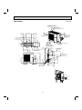
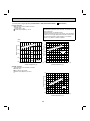
MXZ-3A30NA
Unit: inch
REQUIRED SPACE
Open as a rule
More than 19.69 in.
if the front and both sides are
open
15-1/4"
1-3/16" 12-19/32"
2-15/32" x 1-13/32" Oval hole
(Base bolt M10)
Indoor and outdoor
connect wiring
4- 7/8" hole
2-11/16"
C unit connection
1-5/16"
35-7/16"
15"
18-1/8"
1-31/32"
9-27/32"
35-7/16"
12-1/2"
13/32"
29/32"
B unit connection
Gas pipe
3/8" flared (B,C unit)
1/2" flared (A unit)
29-9/16"
Drain hole 3- 1-5/16"
More than 13.78 in.
Open as a rule
More than 19.69 in.
if the back, both sides
and top are open
1-1/4"
Air out
1-9/16"
2-29/32"
Air in
13-31/32" (5/8")
Air in
(5/8")
1-3/8"
2-U-shape notched holes
(Base bolt M10)
More than 3.94 in.
More than 7.87 in.
if there are
obstacles to both
sides
More than 3.94 in.
10-5/8"
3-25/32"
1-3/8" 9-27/32"
(7-7/8")
A unit connection
3-15/32"
Liquid pipe
1/4" flared
29/32"
19-11/16"
(1-1/16")
7-7/8"
Lock nut
Conduit cover
Connector
23
Unit: inch
1
7-7/8"
7-7/8"
10-5/8"
Air in
5/8"
Air out
1-9/16"
Drain hole 3- 1-5/16"
14"
(Bolt pitch)
15-1/4"
15/16" 7/16"
Air in
2-U Shaped notched hole
(Base bolt M10)
5/8"
1-3/8"
1-3/8"
2-29/32"
9-27/32"
19-11/16"
1-1/16"
MXZ-3A30NA -
2-(15/32" x 1-13/32") Oval hole
(Base bolt M10)
3- 7/8"Punched hole
(Connect wiring hole)
35-7/16"
2- 7/8"Knockout
(Connect wiring hole)
Handle
1-3/16"
12-19/32"
13/32"
19-1/8"
B
A
Gas pipe
3/8 (B,C unit)
1/2 (A unit)
C unit connection
B unit connection
A unit connection
Liquid pipe
1/4 flared
More than 3-15/16"
More than 7-7/8"
Lock nut
Connector
Conduit cover
More than13-25/32"
More than 19-11/16"
More than 3-15/16"
2.Service space
More than 19-11/16"
Note : Leave front and overhead
clearance fully.
Note : Leave rear, overhead and
both sides clearance fully.
3-15/32"
C
More than 3-15/16"
Note : Leave front and both sides
clearance fully.
More than 19-11/16"
1.Installation space
29/32"
5-3/16"
12-1/2"
1-25/32"
18-1/8"
8-27/32"
35-7/16"
4-3/4"
1-3/16"
Handle
More than 3-15/16"
More than 13-25/32"
24
SERVICE SPACE
More than 13-25/32"
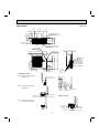
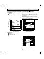
MXZ-4A36NA
Unit: inch
7-7/8"
7-7/8"
10-5/8"
Air in
5/8"
Air out
1-9/16"
Drain hole 3- 1-5/16"
14"
(Bolt pitch)
15-1/4"
5/8"
15/16" 7/16"
Air in
2-U Shaped notched hole
(Base bolt M10)
1-1/16"
1-3/8"
1-3/8"
2-29/32"
9-27/32"
19-11/16"
2-(15/32" x 1-13/32") Oval hole
(Base bolt M10)
3- 7/8"Punched hole
(Connect wiring hole)
35-7/16"
1-3/16"
2- 7/8"Knockout
(Connect wiring hole)
Handle
12-19/32"
13/32"
4-3/4"
35-7/16"
D
19-1/8"
C
B
A
Gas pipe
3/8 (B,C,D unit)
1/2 (A unit)
D unit connection
C unit connection
B unit connection
A unit connection
Liquid pipe
1/4 flared
More than 3-15/16"
Lock nut
More than13-25/32"
More than 19-11/16"
More than 3-15/16"
Conduit cover
2.Service space
Connector
More than 19-11/16"
More than 7-7/8"
Note : Leave front and overhead
clearance fully.
Note : Leave rear, overhead and
both sides clearance fully.
3-15/32"
More than 3-15/16"
Note : Leave front and both sides
clearance fully.
More than 19-11/16"
1.Installation space
29/32"
5-3/16"
12-1/2"
1-25/32"
18-1/8"
12-13/32"
1-3/16"
Handle
More than 3-15/16"
More than 13-25/32"
25
SERVICE SPACE
More than 13-25/32"
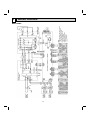
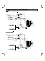
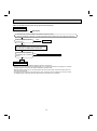
6
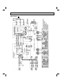
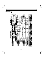
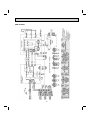
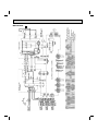
WIRING DIAGRAM
MXZ-2A20NA
26
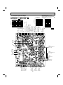
MXZ-2A20NA -
1
27
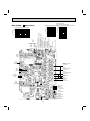
MXZ-2A20NA -
2
28
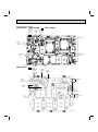
MXZ-3A30NA
29
MXZ-3A30NA -
1
30
SYMBOL
CB1~3
CT1,2
CT61
F64
F65
F801
F931
S3
S2
S1 TB2
S3
S2
S1 TB3
S3
S2
S1 TB4
S3
S2
S1 TB5
BLU
BLK
NAME
SMOOTHING CAPACITOR
CURRENT TRANSFORMER
CURRENT TRANSFORMER
FUSE(T2AL250V)
FUSE(T6.3AL250V)
FUSE(T3.15AL250V)
FUSE(T3.15AL250V)
208/230V
1PH. 60Hz
TO INDOOR
UNIT No.A
12-24V
CONNECTING
208/230V
1PH. 60Hz
TO INDOOR
UNIT No.B
12-24V
CONNECTING
208/230V
1PH. 60Hz
TO INDOOR
UNIT No.C
12-24V
CONNECTING
208/230V
1PH. 60Hz
TO INDOOR
UNIT No.D
12-24V
CONNECTING
L2
BLU
BLU
BLK
BLU
BLK
POWER SUPPLY
208/230V
1phase 60Hz
TB1
BLK
L1
BLK
BLU
RED
ORN
GRY
BRN
CN631
MC
LEV A~D
LEV F
SYMBOL
HC930
HPS
IPM
L
1 2 3
1 2 3
TAB2
TAB1
NAME
INTELLIGENT POWER MODULE
HIGH PRESSURE SWITCH
INTELLIGENT POWER MODULE
REACTOR
EXPANSION VALVE
EXPANSION VALVE
COMPRESSOR
LEV D
TAB4
3
3
WHT
BLK
BLK
BLK
2
BLK
CN681
1 2
HPS
CN661
1 2 3 4 5 6 7 8
RT62
SSR61
RT68
SYMBOL
RT61
RT62
RT64
RT65
RT61
4
YLW
RED
RT65
CN4
1 2
CN796
1 2 3 4 5 6
1 2
CN701
LEV F
NAME
DEFROST THERMISTOR
DISCHARGE TEMP.THERMISTOR
FIN TEMP.THERMISTOR
AMBIENT TEMP.THERMISTOR
OUTDOOR HEAT EXCHANGER
TEMPERATURE THERMISTOR
SOLENOID COIL RELAY
RT68
CN663
1 2
S
R
CN5
1
1 2 3 4 5 6 7
CN702
L
CONTROL P.C.BOARD
SYMBOL
NAME
FAN MOTOR
MF
VARISTOR
NR64
N/F
NOISE FILTER
PFC
POWER FACTOR CONTROLLER
RESISTOR
R64A,B
RESISTOR
R930A,B
RS1~4
RESISTOR
LEV C
LEV B
ELECTRONIC
1 2 3 4 5
CN781
LEV A
21S4
1 2 3 4 5
CN901
R64B
(GRN)
CN794
1 2 3 4 5 6
BLK
BLK
1 2 CN912
SSR61
NR64
R64A
(BLU)
CN793
1 2 3 4 5 6
LDE2
LDE1
N/F
F64
(RED)
CN792
1 2 3 4 5 6
F65
(WHT)
CN791
1 2 3 4 5 6
CN61
1 2 3
GROUND
N/F
RED
BRN
BLU
ORN
YLW
WHT
1 2 3
CN621
CN611
CN601
1 2 3 4 5
BLU
BLU
RED
BRN
BLU
ORN
YLW
WHT
BLU
BLK
BLK
2 1
7 6 5 4 3 2 1
CN2
BLK
BLK
N
RED
BRN
BLU
ORN
YLW
WHT
RS2
RS1
F801
LD2
CB1
RS4
RS3
CB3
R930B
R930A
F931
1 2 3 CN801
LD1
CB2
POWER BOARD
WHT
SYMBOL
NAME
T801
TRANSFORMER
TB1~5
TERMINAL BLOCK
X64
RELAY
21S4 REVERSING VALVE SOLENOID COIL
T801
PFC
RED
X64
RED
RED
BLK
BLK
BLK
RED
BRN
BLU
ORN
YLW
WHT
BLK
GRY
GRY
CT2
W
V
U
CN932
CN931
U
YLW
BLU
ORN
PNK
GRY
BLK
WHT
RED
BLK
BLK
RED
WHT
BLK
NOTES:
1.About the indoor side electric
wiring refer to the indoor unit
electric wiring diagram for
servicing.
2.Use copper conductors only
(For field wiring).
3.Symbols below indicate.
:Terminal block
:connector
HC930
BLK
LD9
IPM
CT1
CN3
1 2
CT61
GRY
GRY
BLK
BLK
BLK
BLK
BLK
GRY
GRY
31
3 2 1
1 2
CN902
5 4 3 2 1
1 2
CN903
RED
BRN
BLU
ORN
YLW
WHT
MF
MC
V
W
RT64
NOISE FILTER
P.C.BOARD
MXZ-4A36NA
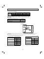
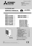
REFRIGERANT SYSTEM DIAGRAM
7
MXZ-2A20NA
MXZ-2A20NA -
Unit: mm
1
Service
port
Compressor
R.V. coil
OFF
ON
Indoor unit
B
Unit B gas pipe
temperature thermistor *
Discharge
temperature
thermistor RT62
Oil separator
Capillary tube
O.D.0.10 x I.D.0.02 x 39.37
Ball valve with
service port
Unit A gas pipe
temperature thermistor *
4-way valve
Muffler
Outdoor heat
exchanger
temperature
thermistor
RT68
FAN-OUT
HEX-OUT
Indoor unit
A
Refrigerant flow in cooling
Refrigerant flow in heating
Service
port
Indoor unit
A
Ambient
temperature
thermistor
RT65
Defrost
thermistor
RT61
Capillary tube
O.D.0.16 x I.D.0.11 x 3.93
Strainer
#100
Capillary tube
O.D.0.14 x I.D.0.09 x 19.68
LEV A
Ball valve
Strainer
#100
Strainer
#100
LEV E
Power
receiver
Indoor unit
B
Distributor
Capillary tube
O.D.0.16 x I.D.0.11 x 3.93
Strainer
#100
* Except MXZ-2A20NA -
MXZ-2A20NA -
LEV B
1
.
2
Service
port
Compressor
R.V. coil
OFF
ON
Refrigerant flow in cooling
Refrigerant flow in heating
Oil separator
Stop valve with
service port
Indoor unit
B
Discharge
temperature
thermistor RT62
Service
port
Capillary tube
O.D.0.10 x I.D.0.02 x 39.37
4-way valve
Muffler
Indoor unit
A
Outdoor heat
exchanger
temperature
thermistor
RT68
HEX-OUT
FAN-OUT
Indoor unit
A
Defrost
thermistor
RT61
Capillary tube
O.D.0.16 x I.D.0.11 x 3.93
Strainer
#100
Capillary tube
O.D.0.14 x I.D.0.09 x 19.68
LEV A
Stop valve
Strainer
#100
LEV E
Power
receiver
Indoor unit
B
Ambient
temperature
thermistor
RT65
Capillary tube
O.D.0.16 x I.D.0.11 x 3.93
Strainer
#100
LEV B
32
Strainer
#100
Distributor
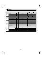
Operating Range
Cooling
Heating
MXZ-2A20NA
Maximum
Minimum
Maximum
Minimum
MXZ-2A20NA -
MXZ-2A20NA -
1
2
Indoor intake air temperature Outdoor intake air temperature
115°FDB
95°FDB, 71°FWB
14°FDB
67°FDB, 57°FWB
75°FDB, 65°FWB
80°FDB, 67°FWB
14°FDB, 12°FWB
70°FDB, 60°FWB
MAX. REFRIGERANT PIPING LENGTH & PIPE SIZE SELECTION
MXZ-2A20NA
MXZ-2A20NA -
1
MXZ-2A20NA -
2
Piping length each indoor unit (a, b)
82 ft. MAX.
Total piping length (a+b)
164 ft. MAX.
Bending point for each unit
25 MAX.
Total bending point
60 MAX.
It does not matter which unit is higher.
Indoor
units
a
Outdoor
unit
49 ft.
49 ft.
33 ft.
b
Refrigerant pipe diameter is different according to indoor unit to be connected. When using extension pipes, refer to the
tables below.
When diameter of refrigerant pipe is different from that of outdoor unit union, use optional Different-diameter pipe.
For further information on Different-diameter pipe, see 15-1.
Unit : inch
Outdoor unit union diameter
Indoor unit class
Extension pipe diameter
For
Liquid
1/4
Liquid
1/4
09
Indoor unit A
Gas
3/8
Gas
3/8
Liquid
1/4
Liquid
1/4
12
Indoor unit B
Gas
3/8
Gas
3/8
Liquid
1/4
15
Gas
1/2
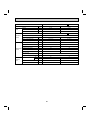
33
Service
port
MXZ-3A30NA
R.V. coil
OFF
ON
Indoor unit
C
Indoor unit
B
Indoor unit
A
Refrigerant flow in cooling
Refrigerant flow in heating
Unit C gas pipe
temperature thermistor
Unit: mm
Service Compressor
port
Discharge
High-pressure
temperature
switch
thermistor RT62
Oil separator
Ball valve with
service port
Capillary tube
O.D.0.10 x I.D.0.02 x 39.37
4-way valve
Unit B gas pipe
temperature thermistor
Muffler
Unit A gas pipe
temperature thermistor
Outdoor
heat
exchanger
Ambient
temperature
thermistor
Outdoor heat RT65
exchanger
temperature
thermistor
RT68
Capillary tube
O.D.0.16 x I.D.0.11 x 3.54
Indoor unit
A
Indoor unit
B
Indoor unit
C
Strainer
#100
Strainer
#100
LEV B
Strainer
#100
LEV C
Ball valve Strainer
#100
LEV E
Strainer
#100
Capillary tube
O.D. 0.16 x I.D. 0.09 x 15.75
Distributor
Power
receiver
Distributor
MXZ-3A30NA R.V. coil
OFF
ON
LEV A
Defrost
thermistor
RT61
1
Unit: mm
Service port
Compressor
Service
port
Discharge
temperature
Refrigerant flow in cooling High-pressure
thermistor RT62
switch
Refrigerant flow in heating
Oil separator
Indoor unit
C
Stop valve
(with service port)
Indoor unit
B
Indoor unit
A
Muffler
Capillary tube
O.D.0.10 x I.D.0.02 x 39.37
4-way valve
Outdoor
heat
exchanger
Outdoor heat
exchanger
temperature
thermistor
RT68
Capillary tube
O.D.0.16 x I.D.0.11 x 3.94
Indoor unit
A
Indoor unit
B
Indoor unit
C
Strainer
#100
LEV A
Strainer
#100
LEV B
Strainer
#100
LEV C
Ambient
temperature
thermistor
RT65
Defrost
thermistor
RT61
Stop valve Strainer
#100
LEV F
Power
receiver
34
Strainer
#100
Capillary tube
O.D.0.12 x I.D.0.08 x 11.8
Distributor
Operating Range
MXZ-3A30NA MXZ-3A30NA -
Indoor intake air temperature Outdoor intake air temperature
115°FDB
95°FDB, 71°FWB
14°FDB
67°FDB, 57°FWB
75°FDB, 65°FWB
80°FDB, 67°FWB
14°FDB, 12°FWB
70°FDB, 60°FWB
Maximum
Minimum
Maximum
Minimum
Cooling
Heating
1
MAX. REFRIGERANT PIPING LENGTH & PIPE SIZE SELECTION
MXZ-3A30NA MXZ-3A30NA -
1
Piping length each indoor unit (a, b, c)
82 ft. MAX.
Total piping length (a+b+c)
230 ft. MAX.
Bending point for each unit
25 MAX.
Total bending point
70 MAX.
It does not matter which unit is higher.
Indoor
units
a
Outdoor
unit
b
33 ft.
(MXZ-3A30NA)
49 ft.
(MXZ-3A30NA -
1
ft.
) 33
(MXZ-3A30NA)
49 ft.
(MXZ-3A30NA -
1
)
33 ft.
c
Refrigerant pipe diameter is different according to indoor unit to be connected. When using extension pipes, refer to the
tables below.
When diameter of refrigerant pipe is different from that of outdoor unit union, use optional Different-diameter pipe.
For further information on Different-diameter pipe, see 15-1.
Unit : inch
Indoor unit class
09
12
15
17
24
Outdoor unit union diameter
Extension pipe diameter
Liquid
1/4
For
Liquid
1/4
Gas
3/8
Liquid
1/4
Gas
1/2
Gas
3/8
Liquid
1/4
Liquid
1/4
Gas
3/8
Gas
1/2
Liquid
1/4
Liquid
1/4
Gas
3/8
Gas
1/2
Liquid
1/4
Gas
5/8
Indoor unit A
Indoor unit B
Indoor unit C
35
MXZ-4A36NA
R.V. coil
OFF
ON
Unit: mm
Service port
Compressor
Service
port
Discharge
temperature
Refrigerant flow in cooling High-pressure
thermistor RT62
switch
Refrigerant flow in heating
Oil separator
Indoor unit
D
Stop valve
(with service port)
Indoor unit
C
Indoor unit
B
Indoor unit
A
Capillary tube
O.D.0.10 x I.D.0.02 x 39.37
4-way valve
Muffler
Outdoor
heat
exchanger
Outdoor heat
exchanger
temperature
thermistor
RT68
Capillary tube
O.D.0.16 x I.D.0.11 x 3.94
Indoor unit
A
Indoor unit
B
Indoor unit
C
Indoor unit
D
Strainer
#100
Defrost
thermistor
RT61
LEV A
Strainer
#100
LEV B
Strainer
#100
LEV C
Strainer
#100
LEV D
Ambient
temperature
thermistor
RT65
Stop valve Strainer
#100
LEV F
Power
receiver
36
Strainer
#100
Capillary tube
O.D.0.12 x I.D.0.08 x 11.8
Distributor
Operating Range
MXZ-4A36NA
Indoor intake air temperature Outdoor intake air temperature
115°FDB
95°FDB, 71°FWB
14°FDB
67°FDB, 57°FWB
75°FDB, 65°FWB
80°FDB, 67°FWB
14°FDB, 12°FWB
70°FDB, 60°FWB
Maximum
Minimum
Maximum
Minimum
Cooling
Heating
MAX. REFRIGERANT PIPING LENGTH & PIPE SIZE SELECTION
MXZ-4A36NA
Piping length each indoor unit (a, b, c, d)
82 ft. MAX.
Total piping length (a+b+c+d)
230 ft. MAX.
Bending point for each unit
25 MAX.
Total bending point
70 MAX.
It does not matter which unit is higher.
Indoor
units
a
b
Outdoor
unit
49 ft.
49 ft.
c
33 ft.
d
Refrigerant pipe diameter is different according to indoor unit to be connected. When using extension pipes, refer to the
tables below.
When diameter of refrigerant pipe is different from that of outdoor unit union, use optional Different-diameter pipe.
For further information on Different-diameter pipe, see 15-1.
Unit : inch
Indoor unit class
09
12
15
17
24
Outdoor unit union diameter
Extension pipe diameter
Liquid
1/4
For
Liquid
1/4
Gas
3/8
Liquid
1/4
Gas
1/2
Gas
3/8
Liquid
1/4
Liquid
1/4
Gas
3/8
Gas
1/2
Liquid
1/4
Liquid
1/4
Gas
3/8
Gas
1/2
Liquid
1/4
Gas
3/8
Liquid
1/4
Gas
5/8
Indoor unit A
Indoor unit B
Indoor unit C
Indoor unit D
37
8
DATA
Model
MXZ-2A20NA MXZ-2A20NA -
Item
Cooling
Heating
Btu / h
20,000
22,000
SHF
—
–
–
Input
kW
2.15
1
MXZ-2A20NA -
2
208/230, 1, 60
Power supply (V, phase, Hz)
kW
2.113
1.743
Comp. current (208/230V)
A
10.08/9.11
8.24/7.45
Fan motor current (208/230V)
A
0.43/0.39
0.43/0.39
Condensing pressure
PSIG
435
363
Suction pressure
PSIG
128
101
°F
190
169
°F
122
106
Input
Discharge temperature
Refrigerant Condensing temperature
circuit
Suction temperature
°F
65
40
Comp. shell bottom temp.
Ref. pipe length
[Total pipe length for multi-system]
°F
146
144
ft.
25 [50]
Refrigerant charge (R410A)
—
5 lb.15 oz.
DB
°F
95
47
WB
°F
—
43
Fan speed
rpm
650
700
Airflow
CFM
1,485
1,640
Intake air temperature
Outdoor
unit
1.78
MXZ-2A20NA MXZ-2A20NA -
Outdoor unit
Electrical
circuit
MXZ-2A20NA -
Unit
Capacity
Total
1
38
2
Model
MXZ-3A30NA MXZ-3A30NA -
Item
Unit
Cooling
Heating
Btu / h
28,400
28,600
SHF
—
–
–
Input
kW
3.25
Capacity
Total
1
208/230, 1, 60
Power supply (V, phase, Hz)
kW
3.197
2.127
Comp. current (208/230V)
A
15.45/13.97
10.15/9.18
Fan motor current (208/230V)
A
0.43/0.39
0.43/0.39
Condensing pressure
PSIG
506
330
Suction pressure
PSIG
136
96
°F
190
150
°F
132
100
Input
Discharge temperature
Refrigerant Condensing temperature
circuit
Suction temperature
°F
48
30
Comp. shell bottom temp.
Ref. pipe length
[Total pipe length for multi-system]
°F
146
125
ft.
25 [75]
Refrigerant charge (R410A)
—
7 lb.11 oz.
DB
°F
95
47
WB
°F
—
43
Fan speed
rpm
520
600
Airflow
CFM
1,365
1,605
Intake air temperature
Outdoor
unit
2.18
MXZ-3A30NA MXZ-3A30NA -
Outdoor unit
Electrical
circuit
1
39
Model
MXZ-4A36NA
Item
Unit
Cooling
Heating
Btu / h
36,000
36,000
SHF
—
–
–
Input
kW
3.82
3.1
Capacity
Total
MXZ-4A36NA
Outdoor unit
Electrical
circuit
208/230, 1, 60
Power supply (V, phase, Hz)
kW
3.756
Comp. current (208/230V)
A
17.85 / 16.14
14.36 /12.98
Fan motor current (208/230V)
A
0.43 / 0.39
0.43 / 0.39
Condensing pressure
PSIG
458
338
Suction pressure
PSIG
136
93
°F
194
158
°F
125
100
°F
62
44
Comp. shell bottom temp.
Ref. pipe length
[Total pipe length for multi-system]
°F
180
ft.
25 [100]
Refrigerant charge (R410A)
—
8 lb.13 oz.
Input
Discharge temperature
Refrigerant Condensing temperature
circuit
Suction temperature
140
DB
°F
95
47
WB
°F
—
43
Fan speed
rpm
750
750
Airflow
CFM
2,068
2,068
Intake air temperature
Outdoor
unit
3.036
40
8-1. OPERATING RANGE
(1) POWER SUPPLY
MXZ-2A20NA
MXZ-2A20NA MXZ-2A20NA MXZ-3A30NA
MXZ-3A30NA MXZ-4A36NA
Outdoor unit
Guaranteed Voltage
Rating
Model
1
2
Min. 198 V 208 V 230 V Max. 253 V
208/230 V 60 Hz 1
1
(2) OPERATION
Function
Cooling
Heating
Intake air
temperature
Condition
"A" Cooling steady state
at rated compressor speed
"B-2" Cooling steady state
at rated compressor speed
"B-1" Cooling steady state
at minimum compressor speed
Low ambient cooling steady state
at minimum compressor speed
Intermediate cooling steady state
at intermediate compressor speed
Standard rating-heating
at rated compressor speed
Low temperature heating
at rated compressor speed
Max. temperature heating
at minimum compressor speed
High temperature heating
at minimum compressor speed
Frost accumulation
at rated compressor speed
Frost accumulation
at intermediate compressor speed
Outdoor
Indoor
DB (°F)
WB (°F)
DB (°F)
WB (°F)
80
67
95
(75)
80
67
82
(65)
80
67
82
(65)
80
67
67
(53.5)
80
67
87
(69)
70
60
47
43
70
60
17
15
70
60
62
56.5
70
60
47
43
70
60
35
33
70
60
35
33
At intermediate compressor speed
=("Cooling rated compressor speed" - "minimum compressor speed") / 3 + "minimum compressor speed".
41
MXZ-2A20NA MXZ-2A20NA -
1
MXZ-2A20NA -
2
MXZ-3A30NA MXZ-3A30NA -
1
MXZ-4A36NA
The standard specifications apply only to the operation of the air conditioner under normal conditions.
Since operating conditions vary according to the areas where these units are installed, the following information has been provided to clarify the operating characteristics of the air conditioner under the conditions indicated by the performance curve.
(1) GUARANTEED VOLTAGE
198 ~ 253 V 60 Hz
(2) AIR FLOW
Air flow should be set at MAX.
(3) MAIN READINGS
(1) Indoor intake air wet-bulb temperature :
(2) Indoor outlet air wet-bulb temperature :
(3) Outdoor intake air dry-bulb temperature :
(4) Total input:
°FWB
°FWB
°FDB
W
}
Cooling
}
(5) Indoor intake air dry-bulb temperature :
°FDB
Heating
(6) Outdoor intake air wet-bulb temperature :
°FWB
(7) Total input :
W
Indoor air wet/dry-bulb temperature difference on the left side of the following chart shows the difference between the
indoor intake air wet/dry-bulb temperature and the indoor outlet air wet/dry-bulb temperature for your reference at service.
How to measure the indoor air wet-bulb/dry-bulb temperature difference
1.
2.
3.
4.
5.
6.
7.
8.
Attach at least 2 sets of wet-and dry-bulb thermometers to the indoor air intake as shown in the figure, and at least 2 sets
of wet-and dry-bulb thermometers to the indoor air outlet. The thermometers must be attached to the position where air
speed is high.
Attach at least 2 sets of wet-and dry-bulb thermometers to the outdoor air intake.
Cover the thermometers to prevent direct rays of the sun.
Check that the air filter is cleaned.
Open windows and doors of room.
Press the EMERGENCY OPERATION switch once (twice) to start the EMERGENCY COOL (HEAT) MODE.
Compressor starts running at 33 Hz (COOL) or 45 Hz (HEAT). The frequency at each operation mode is fixed.
When system stabilizes after more than 15 minutes, measure temperature and take an average temperature.
10 minutes later, measure temperature again and check that the temperature does not change.
INDOOR UNIT
OUTDOOR UNIT
Wet-and dry-bulb
thermometers
42
Wet-and dry-bulb
thermometers
14.0
16.7 20.0
13.0
15.3 18.4
11.9
14.0 16.6
10.6
13.0 14.9
79
43.4 53.1
36.5
39.8 48.6
33.3
36.0 44.3
29.9
32.4 39.8
26.6
28.8 35.5
23.2
25.2 31.0
20.0
21.6 26.5
15 class
(75Hz)
40.0
68
64
80
85
90
95
100
105
110
80
ir
ea
y-b
Dr
ul
ure
rat
pe
em
t
b
85
ta
r in
90
95
59
68
79
)
(°F
Indo
k
100
105
110
ture
pera
tem
bulb
y
r
air D
take
14
23
32
41
50
59
14
Outdoor intake air Wet-bulb temperature (°F)
or in
23
32
41
50
1
MXZ-4A36NA
22.0 19.6
13.0
15.3 18.4
20.2 18.0
11.9
14.0 16.6
18.2 16.4
10.6
13.0 14.9
16.4 14.8
9.5
11.3 13.5
14.8 13.1
72
8.6
10.1 11.9
13.0 11.7
68
79
39.8 48.6
54.4
42.1
33.3
36.0 44.3
49.3
38.2
29.9
32.4 39.8
44.5
34.4
26.6
28.8 35.5
39.4
30.6
23.2
25.2 31.0
34.6
26.8
20.0
21.6 26.5
29.7
22.9
24 class
(72Hz)
15 class
(56Hz)
85
90
95
100
105
45.9
36.5
72
68
64
64
80
110
49.7
17 class
(60Hz)
59.2
75
75
24 class
(56Hz)
12 class
(27Hz)
64.3
12 class
(42Hz)
43.4 53.1
17 class
(40Hz)
09 class
(20Hz)
15 class
(36Hz)
79
40.0
59
NOTE: The above broken lines are for the heating operation without any frost and defrost operation.
16.7 20.0
47.0 57.4
79
68
59
Outdoor intake air Wet-bulb temperature (°F)
14.0
43.2
(°F)
oo
Ind
09 class
(34Hz)
Indoor air WB temperature
difference (degree)
Indoor unit class
(Inverter output
frequency)
Indoor air DB temperature
difference (degree)
72
68
64
72
MXZ-3A30NA MXZ-3A30NA -
Indoor unit class
(Inverter output
frequency)
75
75
47.0 57.4
12 class
(56Hz)
43.2
2
79
15 class
(77Hz)
10.1 11.9
12 class
(50Hz)
11.3 13.5
8.6
09 class
(36Hz)
9.5
09 class
(45Hz)
Indoor unit class
(Inverter output
frequency)
Indoor air DB temperature
difference (degree)
Indoor unit class
(Inverter output
frequency)
Indoor air WB temperature
difference (degree)
8-2. CAPACITY AND THE INPUT CURVES
MXZ-2A20NA MXZ-2A20NA - 1 MXZ-2A20NA -
e
tur
ra
pe
Ind
14
oo
r in
23
tak
ir
ea
Dr
32
y-b
ul
)
(°F
80
85
90
100
105
59
68
79
110
ure
erat
(°F)
mp
lb te
em
bt
take
or in
Indo
41
95
50
Outdoor intake air Wet-bulb temperature (°F)
59
14
23
u
ry-b
air D
32
41
50
79
68
59
59
Outdoor intake air Wet-bulb temperature (°F)
NOTE: The above broken lines are for the heating operation without any frost and defrost operation.
43
8-3. Capacity and input correction by means of inverter output frequency
(OUTDOOR UNIT : MXZ-2A20NA MXZ-2A20NA -
MXZ-2A20NA -
1
2
)
1. 09-class unit in single operation
<COOL>Capacity
2.0
<COOL>Total input
2.0
<HEAT>Capacity
2.0
1.5
1.5
1.5
1.5
1.0
1.0
1.0
1.0
0.5
0.5
0.5
0.5
0
50
0
100 Hz
Frequency
50
Frequency
100 Hz
0
50
<HEAT>Total input
2.0
100 Hz
0
Frequency
50
Frequency
100 Hz
2. 12-class unit in single operation
<COOL>Capacity
2.0
<COOL>Total input
2.0
<HEAT>Capacity
2.0
1.5
1.5
1.5
1.5
1.0
1.0
1.0
1.0
0.5
0.5
0.5
0.5
0
50
100 Hz
0
Frequency
50
Frequency
100 Hz
0
50
<HEAT>Total input
2.0
0
100 Hz
Frequency
50
Frequency
100 Hz
3. 15-class unit in single operation
<COOL>Capacity
2.0
<COOL>Total input
2.0
<HEAT>Capacity
2.0
1.5
1.5
1.5
1.5
1.0
1.0
1.0
1.0
0.5
0.5
0.5
0.5
0
50
Frequency
100 Hz
0
50
Frequency
100 Hz
44
0
50
Frequency
<HEAT>Total input
2.0
100 Hz
0
50
Frequency
100 Hz
(OUTDOOR UNIT: MXZ-3A30NA MXZ-3A30NA -
1
MXZ-4A36NA )
1. 09-class unit in single operation
<COOL>Capacity
2.0
<COOL>Total input
2.0
<HEAT>Capacity
2.0
1.5
1.5
1.5
1.5
1.0
1.0
1.0
1.0
0.5
0.5
0.5
0.5
0
50
0
100 Hz
Frequency
50
Frequency
100 Hz
0
50
<HEAT>Total input
2.0
100 Hz
0
Frequency
50
Frequency
100 Hz
2. 12-class unit in single operation
<COOL>Capacity
2.0
<COOL>Total input
2.0
<HEAT>Capacity
2.0
1.5
1.5
1.5
1.5
1.0
1.0
1.0
1.0
0.5
0.5
0.5
0.5
0
50
100 Hz
0
Frequency
50
Frequency
100 Hz
0
50
<HEAT>Total input
2.0
0
100 Hz
Frequency
50
Frequency
100 Hz
3. 15-class unit in single operation
<COOL>Capacity
2.0
<COOL>Total input
2.0
<HEAT>Capacity
2.0
1.5
1.5
1.5
1.5
1.0
1.0
1.0
1.0
0.5
0.5
0.5
0.5
0
50
0
100 Hz
Frequency
50
Frequency
100 Hz
0
50
<HEAT>Total input
2.0
100 Hz
0
Frequency
50
Frequency
100 Hz
4. 17-class unit in single operation
<COOL>Capacity
2.0
<COOL>Total input
2.0
<HEAT>Capacity
2.0
1.5
1.5
1.5
1.5
1.0
1.0
1.0
1.0
0.5
0.5
0.5
0.5
0
50
0
100 Hz
Frequency
50
Frequency
100 Hz
0
50
<HEAT>Total input
2.0
100 Hz
0
Frequency
50
Frequency
100 Hz
5. 24-class unit in single operation
<COOL>Capacity
2.0
<COOL>Total input
2.0
<HEAT>Capacity
2.0
1.5
1.5
1.5
1.5
1.0
1.0
1.0
1.0
0.5
0.5
0.5
0.5
0
50
Frequency
100 Hz
0
50
Frequency
100 Hz
0
50
Frequency
45
<HEAT>Total input
2.0
100 Hz
0
50
Frequency
100 Hz
8-4. Outdoor low pressure and outdoor unit current
1. 09-class unit in single operation (OUTDOOR UNIT : MXZ-2A20NA MXZ-2A20NA (1) COOL operation
Data is based on the condition of indoor
humidity 50%
Air flow speed : High
Inverter output frequency : 33 Hz
2
)
6.0
re (°F)
mperatu
DB te
Indoor
86
80
150
140
75
130
Outdoor unit current (A)
Outdoor low pressure
MXZ-2A20NA -
<How to work fixed-frequency operation>
1.Set emergency switch to COOL or HEAT. The switch is located on indoor unit.
2.Press emergency run ON/OFF button.
3.Compressor starts running at 33 Hz (COOL) or 45 Hz (HEAT).
4.Indoor fan runs at High speed and continues for 30 minutes.
5.To cancel this operation, press emergency run ON/OFF
button or any button on remote controller.
(PSIG)
170
160
1
70
5.0
F)
re (°
4.0
3.0
m
B te
or D
Indo
tu
pera
86
80
75
70
33 Hz
2.0
1.0
33 Hz
120
65 70 75 80 85 90 95 100 105 110 115 (°F)
0.0
65 70 75 80 85 90 95 100 105 110 115 (°F)
Ambient temperature (°F)
Ambient temperature (°F)
(2) HEAT operation
Data is based on the condition of indoor
humidity 75%
Set air flow to High speed.
Inverter output frequency is 45 Hz.
Outdoor unit current (A)
7.0
6.0
5.0
4.0
or
Indo
re
eratu
emp
t
B
D
(°F)
75
70
65
3.0
45 Hz
2.0
15 20 25 30 35 40 45 50 55 60 65 70 75 (°F)
Ambient temperature (°F)
46
2. 12-class unit in single operation (OUTDOOR UNIT : MXZ-2A20NA MXZ-2A20NA (1) COOL operation
Data is based on the condition of indoor
humidity 50%
Air flow speed : High
Inverter output frequency : 33 Hz
160
r
Indoo
MXZ-2A20NA -
2
)
<How to work fixed-frequency operation>
1.Set emergency switch to COOL or HEAT. The switch is located on indoor unit.
2.Press emergency run ON/OFF button.
3.Compressor starts running at 33 Hz (COOL) or 45 Hz (HEAT).
4.Indoor fan runs at High speed and continues for 30 minutes.
5.To cancel this operation, press emergency run ON/OFF
button or any button on remote controller.
6.0
(˚F)
rature
e
p
m
DB te
86
80
150
75
140
5.0
Outdoor unit current (A)
Outdoor low pressure
(PSIG)
170
1
70
130
4.0
B
or D
Indo
F
re (˚
ratu
e
p
tem
)
86
80
75
70
3.0
33 Hz
2.0
1.0
33 Hz
120
0.0
65 70 75 80 85 90 95 100 105 110 115 (˚F) 65 70 75 80 85 90 95 100 105 110 115 (˚F)
Ambient temperature (˚F)
Ambient temperature (˚F)
(2) HEAT operation
Data is based on the condition of outdoor
humidity 75%.
Set air flow to High speed.
Inverter output frequency is 45 Hz.
Outdoor unit current (A)
7.0
6.0
5.0
F)
re (˚
4.0
Indo
B
or D
tu
pera
tem
75
70
65
3.0
45 Hz
2.0
15 20 25 30 35 40 45 50 55 60 65 70 75 (˚F)
Ambient temperature (˚F)
47
3. 15-class unit in single operation (OUTDOOR UNIT : MXZ-2A20NA MXZ-2A20NA (1) COOL operation
Data is based on the condition of indoor
humidity 50%
Air flow speed : High
Inverter output frequency : 33 Hz
160
F
ure (˚
perat
m
e
t
r DB
Indoo
MXZ-2A20NA -
2
)
<How to work fixed-frequency operation>
1.Set emergency switch to COOL or HEAT. The switch is located on indoor unit.
2.Press emergency run ON/OFF button.
3.Compressor starts running at 33 Hz (COOL) or 45 Hz (HEAT).
4.Indoor fan runs at High speed and continues for 30 minutes.
5.To cancel this operation, press emergency run ON/OFF
button or any button on remote controller.
6.0
)
86
5.0
80
150
75
140
Outdoor unit current (A)
Outdoor low pressure
(PSIG)
170
1
3.0
86
80
75
70
F)
re (˚
4.0
B te
or D
Indo
ratu
mpe
33 Hz
2.0
70
130
1.0
33 Hz
120
0.0
65 70 75 80 85 90 95 100 105 110 115 (˚F) 65 70 75 80 85 90 95 100 105 110 115 (˚F)
Ambient temperature (˚F)
Ambient temperature (˚F)
(2) HEAT operation
Data is based on the condition of outdoor
humidity 75%
Set air flow to High speed.
Inverter output frequency is 45 Hz.
Outdoor unit current (A)
7.0
6.0
5.0
4.0
3.0
( ˚F
ture
a
r
e
mp
B te
or D
o
d
In
)
75
70
65
45 Hz
2.0
15 20 25 30 35 40 45 50 55 60 65 70 75 (˚F)
Ambient temperature (˚F)
48
4. 09-class unit in single operation (OUTDOOR UNIT : MXZ-3A30NA MXZ-3A30NA -
1
MXZ-4A36NA )
(1) COOL operation
Data is based on the condition of indoor
humidity 50%
Air flow speed : High
Inverter output frequency : 33 Hz
Outdoor low pressure
150
F
re (˚
eratu
p
m
B te
or D
Indo
80
140
75
130
70
120
6.0
86
)
Outdoor unit current (A)
(PSIG)
160
<How to work fixed-frequency operation>
1.Set emergency switch to COOL or HEAT. The switch is located on indoor unit.
2.Press emergency run ON/OFF button.
3.Compressor starts running at 33 Hz (COOL) or 45 Hz (HEAT).
4.Indoor fan runs at High speed and continues for 30 minutes.
5.To cancel this operation, press emergency run ON/OFF
button or any button on remote controller.
33 Hz
5.0
4.0
re (˚F
eratu
p
m
B te
or D
Indo
)
86
80
75
70
33 Hz
3.0
2.0
1.0
110
65 70 75 80 85 90 95 100 105 110 115 (˚F)
0.0
65 70 75 80 85 90 95 100 105 110 115 (˚F)
Ambient temperature (˚F)
Ambient temperature (˚F)
(2) HEAT operation
Data is based on the condition of outdoor
humidity 75%.
Set air flow to High speed.
Inverter output frequency is 45 Hz.
Outdoor unit current (A)
7.0
6.0
5.0
4.0
B
rD
oo
d
In
e(
tur
a
r
pe
tem
˚F)
75
70
65
45 Hz
3.0
2.0
15 20 25 30 35 40 45 50 55 60 65 70 75 (˚F)
Ambient temperature (˚F)
49
5. 12-class unit in single operation (OUTDOOR UNIT : MXZ-3A30NA MXZ-3A30NA (1) COOL operation
Data is based on the condition of indoor
humidity 50%
Air flow speed : High
Inverter output frequency : 33 Hz
150
r
Indoo
86
( ˚F )
rature
e
p
m
DB te
75
130
120
6.0
5.0
80
140
MXZ-4A36NA )
<How to work fixed-frequency operation>
1.Set emergency switch to COOL or HEAT. The switch is located on indoor unit.
2.Press emergency run ON/OFF button.
3.Compressor starts running at 33 Hz (COOL) or 45 Hz (HEAT).
4.Indoor fan runs at High speed and continues for 30 minutes.
5.To cancel this operation, press emergency run ON/OFF
button or any button on remote controller.
70
Outdoor unit current (A)
Outdoor low pressure
(PSIG)
160
1
33 Hz
4.0
F
re (˚
ratu
e
p
m
B te
or D
o
d
In
)
86
80
75
70
3.0
33 Hz
2.0
1.0
110
0.0
65 70 75 80 85 90 95 100 105 110 115 (˚F) 65 70 75 80 85 90 95 100 105 110 115 (˚F)
Ambient temperature (˚F)
Ambient temperature (˚F)
(2) HEAT operation
Data is based on the condition of outdoor
humidity 75%.
Set air flow to High speed.
Inverter output frequency is 45 Hz.
Outdoor unit current (A)
7.0
6.0
5.0
r
doo
DB
(
re
atu
r
e
mp
75
70
65
˚F)
te
In
4.0
45 Hz
3.0
2.0
15 20 25 30 35 40 45 50 55 60 65 70 75 (˚F)
Ambient temperature (˚F)
50
6. 15-class unit in single operation (OUTDOOR UNIT : MXZ-3A30NA MXZ-3A30NA (1) COOL operation
Data is based on the condition of indoor
humidity 50%
Air flow speed : High
Inverter output frequency : 33 Hz
6.0
re (˚F
eratu
p
m
e
t
r DB
Indoo
)
86
5.0
Outdoor unit current (A)
Outdoor low pressure
MXZ-4A36NA )
<How to work fixed-frequency operation>
1.Set emergency switch to COOL or HEAT. The switch is located on indoor unit.
2.Press emergency run ON/OFF button.
3.Compressor starts running at 33 Hz (COOL) or 45 Hz (HEAT).
4.Indoor fan runs at High speed and continues for 30 minutes.
5.To cancel this operation, press emergency run ON/OFF
button or any button on remote controller.
(PSIG)
170
160
1
4.0
150
80
(˚F
ure
erat
p
m
B te
or D
Indo
33 Hz
3.0
140
75
86
80
75
70
)
2.0
130
70
1.0
33 Hz
120
0.0
65 70 75 80 85 90 95 100 105 110 115 (˚F) 65 70 75 80 85 90 95 100 105 110 115 (˚F)
Ambient temperature (˚F)
Ambient temperature (˚F)
(2) HEAT operation
Data is based on the condition of outdoor
humidity 75%
Set air flow to High speed.
Inverter output frequency is 45 Hz.
Outdoor unit current (A)
7.0
6.0
5.0
DB
or
o
d
In
(
re
atu
r
e
p
tem
˚F)
75
70
65
4.0
45 Hz
3.0
2.0
15 20 25 30 35 40 45 50 55 60 65 70 75 (˚F)
Ambient temperature (˚F)
51
7. 17-class unit in single operation (OUTDOOR UNIT : MXZ-3A30NA MXZ-3A30NA (1) COOL operation
Data is based on the condition of indoor
humidity 50%
Air flow speed : High
Inverter output frequency : 33 Hz
6.0
re (˚F
eratu
p
m
e
t
r DB
Indoo
)
86
5.0
Outdoor unit current (A)
Outdoor low pressure
MXZ-4A36NA )
<How to work fixed-frequency operation>
1.Set emergency switch to COOL or HEAT. The switch is located on indoor unit.
2.Press emergency run ON/OFF button.
3.Compressor starts running at 33 Hz (COOL) or 45 Hz (HEAT).
4.Indoor fan runs at High speed and continues for 30 minutes.
5.To cancel this operation, press emergency run ON/OFF
button or any button on remote controller.
(PSIG)
170
160
1
4.0
150
80
(˚F
ure
erat
p
m
B te
or D
Indo
33 Hz
3.0
140
75
86
80
75
70
)
2.0
130
70
1.0
33 Hz
120
0.0
65 70 75 80 85 90 95 100 105 110 115 (˚F) 65 70 75 80 85 90 95 100 105 110 115 (˚F)
Ambient temperature (˚F)
Ambient temperature (˚F)
(2) HEAT operation
Data is based on the condition of outdoor
humidity 75%.
Set air flow to High speed.
Inverter output frequency is 45 Hz.
Outdoor unit current (A)
7.0
6.0
5.0
DB
or
o
d
In
(
re
atu
r
e
p
tem
˚F)
75
70
65
4.0
45 Hz
3.0
2.0
15 20 25 30 35 40 45 50 55 60 65 70 75 (˚F)
Ambient temperature (˚F)
52
8. 24-class unit in single operation (OUTDOOR UNIT : MXZ-3A30NA MXZ-3A30NA (1) COOL operation
Data is based on the condition of indoor
humidity 50%
Air flow speed : High
Inverter output frequency : 33 Hz
Outdoor low pressure
170
re (˚F
eratu
p
m
e
t
r DB
Indoo
)
<How to work fixed-frequency operation>
1.Set emergency switch to COOL or HEAT. The switch is located on indoor unit.
2.Press emergency run ON/OFF button.
3.Compressor starts running at 33 Hz (COOL) or 45 Hz (HEAT).
4.Indoor fan runs at High speed and continues for 30 minutes.
5.To cancel this operation, press emergency run ON/OFF
button or any button on remote controller.
7.0
86
6.0
80
160
75
150
140
Outdoor unit current (A)
(PSIG)
180
MXZ-4A36NA )
1
70
5.0
4.0
F)
(˚
ture
a
r
e
p
tem
DB
r
o
Indo
86
80
75
70
33 Hz
3.0
2.0
33 Hz
1.0
130
65 70 75 80 85 90 95 100 105 110 115 (˚F) 65 70 75 80 85 90 95 100 105 110 115 (˚F)
Ambient temperature (˚F)
Ambient temperature (˚F)
(2) HEAT operation
Data is based on the condition of outdoor
humidity 75%
Set air flow to High speed.
Inverter output frequency is 45 Hz.
Outdoor unit current (A)
7.0
6.0
5.0
4.0
3.0
ture
(˚F)
t
r DB
o
Indo
era
emp
75
70
65
45 Hz
2.0
15 20 25 30 35 40 45 50 55 60 65 70 75 (˚F)
Ambient temperature (˚F)
53
9
ACTUATOR CONTROL
MXZ-2A20NA MXZ-2A20NA MXZ-3A30NA MXZ-3A30NA -
MXZ-2A20NA MXZ-4A36NA
1
1
2
Relation between main sensor and actuator
Sensor
Purpose
Discharge temperature thermistor
Protection
4-way
valve
Defrosting Protection
Indoor coil thermistor
Defrosting
Defrost thermistor
Gas pipe temperature thermistor
(MXZ-2A20NA, MXZ-3A30NA)
Control
Protection
Fin temperature thermistor
Control
Ambient temperature thermistor
Protection
Outdoor heat exchanger temperature
Control
Capacity code
10
Compressor
Actuator
Outdoor
LEV
fan motor
SERVICE FUNCTIONS
10-1. Pre-heat control <MXZ-2A20NA -
1
, MXZ-2A20NA -
2
, MXZ-3A30NA -
1
, MXZ-4A36NA >
If moisture gets into the refrigerant cycle, or when refrigerant is liquefied and collected in the compressor, it may interfere
the start-up of the compressor.
To improve start-up condition, the compressor is energized even while it is not operating.
This is to generate heat at the winding.
The compressor uses about 50 W when pre-heat control is turned ON.
Pre-heat control is ON at initial setting.
[How to deactivate pre-heat control]
Turn OFF the power supply for the air conditioner before making the setting.
Set the 4th Dip Switch of SW1 on the outdoor electronic control P.C. board to ON to deactivate pre-heat control function (MXZ-2A20NA - 1 , MXZ-2A20NA - 2 ).
Set the 4th Dip Switch of SW2 on the outdoor electronic control P.C. board to ON to deactivate pre-heat control function (MXZ-3A30NA - 1 , MXZ-4A36NA).
SW1
SW2
ON
ON
1 2 3 4 5 6
1 2 3 4
SW1
SW2
SW871
SW1
ON
MXZ-2A20NA MXZ-2A20NA -
SW2
1
2
ON
1 2 3 4 5 6
1 2 3 4
Turn ON the power supply for the air conditioner.
NOTE: Pre-heat control will be turned OFF when the breaker is turned OFF.
54
MXZ-3A30NA MXZ-4A36NA
1
10-2. Auto line correcting <MXZ-3A30NA -
1
, MXZ-4A36NA >
Outdoor unit has an auto line correcting function which automatically
detects and corrects improper wiring or piping.
Improper wiring or piping can be automatically detected by pressing the piping/wiring correction switch (SW871).
When improper wiring or piping is detected, wiring lines are corrected.
This will be completed in about 10 to 15 minutes.
[How to activate this function]
1. Check that outside temperature is above 0˚C.
(This function does not work when outside temperature is not above 0˚C.)
SW871
2. Check that the stop valves of the liquid pipe and gas pipe are open.
3. Check that the wiring between indoor and outdoor unit is correct.
(If the wiring is not correct, this function does not work.)
4. Turn ON the power supply and wait at least 1 minute.
5. Press the piping/wiring correction switch (SW871) on the electronic control P.C. board.
Do not touch energized parts.
SW871
LED indication during detection:
LED1 (Red) LED2 (Yellow) LED3 (Green)
Lighting
Lighting
Blinking
LED indication after detection:
Indication
LED1 (Red) LED2 (Yellow) LED3 (Green)
Lighting
Goes out
Lighting
Completed (Detected successfully)
Blinking
Blinking
Blinking
Cannot be corrected
Refer to "SAFETY PRECAUTIONS WHEN LED FLASHES"
Other indications
located behind the service panel.
Be sure to check for closed valves, cracked pipes or clogged pipes.
6. Press the switch to cancel.
LED indication after cancel :
LED1 (Red) LED2 (Yellow) LED3 (Green)
Lighting
Lighting
Goes out
NOTE : Indoor unit cannot be operated while this function is activated.
When this function is activated while indoor unit is operating, the operation will be stopped.
Operate indoor unit after the auto line correcting is finished.
Pressing the switch during detection cancels this function.
The record of auto line correcting can be confirmed in the following way:
Press the switch for more than 5 seconds.
LED will show the record of auto correcting for about 30 seconds as shown in the table below:
LED1 (Red)
Once
3 times
Number of blinks
Wiring line
LED2 (Yellow) LED3 (Green)
Once
Lighting
Not corrected
3 times
Corrected
Lighting
NOTE : Activate this function to confirm the correct wiring after replacing the electronic control P.C. board.
(Previous records are deleted when the electronic control P.C. board is replaced.)
The record cannot be shown if auto line correcting is not canceled (Refer to "How to activate this function").
55
11
TROUBLESHOOTING
MXZ-2A20NA MXZ-2A20NA MXZ-3A30NA MXZ-3A30NA -
1
1
MXZ-2A20NA MXZ-4A36NA
2
11-1. Cautions on troubleshooting
1. Before troubleshooting, check the following:
1) Check the power supply voltage.
2) Check the indoor/outdoor connecting wire for mis-wiring.
2. Take care of the following during servicing.
1) Before servicing the air conditioner, be sure to turn off the unit first with the remote controller, and then after confirming the horizontal vane is closed, turn off the breaker and/or disconnect the power plug.
2) Be sure to turn OFF the power supply before removing the front panel, the cabinet, the top panel, and the electronic
control P.C. board.
3) When removing the electrical parts, be careful to the residual voltage of smoothing capacitor.
4) When removing the electronic control P.C. board, hold the edge of the board with care NOT to apply stress on the
components.
5) When connecting or disconnecting the connectors, hold the housing of the connector. DO NOT pull the lead wires.
Housing point
Lead wiring
3. Troubleshooting procedure
1) First, check if the OPERATION INDICATOR lamp on the indoor unit is flashing on and off to indicate an abnormality.
To make sure, check how many times the abnormality indication is flashing on and off before starting service work.
2) If the electronic control P.C. board seems to be defective, check the copper foil pattern for disconnection and the components for bursting and discoloration.
3) When troubleshooting, refer to 11-2. and 11-3. and 11-4.
11-2. Failure mode recall function
This air conditioner can memorize the abnormal condition which has occurred once.
Even though LED indication listed on the troubleshooting check table (11-4.) disappears, the memorized failure details
can be recalled.
This mode is very useful when the unit needs to be repaired for the abnormality which doesn’t recur.
1. Type of failure mode recall function
There are 2 types in failure mode recall function as shown below.
Indoor and outdoor unit failure mode recall function
With this function, failure mode of indoor unit and a part of failure mode of outdoor unit can be recalled.
The details of outdoor unit failure mode recall function
With this function, more detailed failure mode of outdoor unit can be recalled.
Refer to the service manual of indoor unit for how to recall the failure mode and the details of indoor unit failure mode.
The outdoor unit failure mode is indicated by the operation indicator lamp on the indoor unit and the LED of outdoor unit.
See "11-2.2. Outdoor unit failure mode table".
56
2. Outdoor unit failure mode table
The left lamp of
OPERATION INDICATOR
lamp (Indoor unit)
Abnormal point
(Failure mode / protection)
LED indication
Condition
(Outdoor P.C. board)
LED 1 LED 2
Lighting Lighting When overcurrent protection stop is
continuously performed three times
within 1 minute after the compressor
gets started, or when converter
protection stop or bus-bar voltage
protection stop is continuously
performed three times within 3
minutes after start-up.
OFF
2-time flash
None (Normal)
Outdoor power system
3-time flash
Discharge temperature
thermistor
Lighting Once
Defrost thermistor
Ambient temperature thermistor
Fin temperature thermistor
P.C. board temperature
thermistor
Lighting
Lighting
Lighting
Lighting
Outdoor heat exchanger
temperature thermistor
Lighting 9 times
Gas pipe temperature
thermistor A
Lighting 10 times When a short or open circuit is
detected in the thermistor during
cooling.
Lighting 11 times (A,B: MXZ-2A20NA, MXZ-3A30NA)
(C : MXZ-3A30NA)
Gas pipe temperature
thermistor B
Gas pipe temperature
thermistor C
When thermistor shorts or opens
during compressor running.
Once
Twice
3 times
4 times
Correspondence
• Check the connection
of the compressor
connecting wire.
• Refer to 11-6.
"How to check
inverter / compressor".
• Check the stop valve.
• Refer to 11-6. "Check
of outdoor thermistors".
• Replace the outdoor
electronic control
P.C. board.
• Refer to 11-6. "Check
of outdoor thermistors".
Lighting 12 times
4-time flash
Overcurrent
5-time flash
Discharge temperature
Lighting Lighting When discharge temperature exceeds •Check refrigerant circuit
240.8°F during operation.
and refrigerant amount.
• Refer to 11-6. "Check
Compressor can restart if discharge
of LEV".
temperature thermistor reads 212°F or
less 3 minutes later.
6-time flash
High pressure
Lighting Lighting When high-pressure is detected
with the high-pressure switch
(HPS) during operation.
(MXZ-3A30NA,MXZ-3A30NA- 1 , MXZ-4A36NA)
When the outdoor heat exchanger
temperature exceeds 158°F
during cooling or the indoor gas
pipe temperature exceeds 158°F
during heating.
•Check refrigerant circuit
and refrigerant amount.
• Check the stop valve.
7-time flash
Fin temperature
3 times
Goes
out
When the fin temperature exceeds
188.6°F during operation.
P.C. board temperature
4 times
Goes
out
When the P.C. board temperature
exceeds 158°F during operation.
• Check around outdoor
unit.
• Check outdoor unit air
passage.
• Refer to 11-6. "Check
of outdoor fan motor".
8-time flash
Outdoor fan motor
Lighting Lighting When failure occurs continuously
three times within 30 seconds after
the fan gets started.
• Refer to 11-6. "Check
of outdoor fan motor".
9-time flash
Nonvolatile memory data
Lighting 5 times When nonvolatile memory data
cannot be read properly.
10-time flash
Discharge temperature
Lighting Lighting When the frequency of the
compressor is kept 80Hz or
more and the discharge
temperature is kept under 102.2°F
for more than 20 minutes.
• Replace the outdoor
electronic control
P.C. board.
•Check refrigerant circuit
and refrigerant amount.
• Refer to 11-6. "Check
of LEV".
Once Goes out When 28A current flows into intelligent
power module.
• Reconnect compressor
connector.
• Refer to 11-6. "How to
check inverter/
compressor".
• Check the stop valve.
NOTE : Blinking patterns of this mode differ from the ones of Troubleshooting check table (11-4.).
57
Indoor/outdoor
unit failure mode
recall function
The left lamp of
OPERATION INDICATOR
lamp(Indoor unit)
11-time flash
15-time flash
LED indication
(Outdoor P.C. board)
LED 1 LED 2
Abnormal point
(Failure mode / protection)
Correspondence
Condition
Communication error
between P.C. boards
Lighting 6 times
Communication error occurs
between the electronic control P.C.
board and power board for more
than 10 seconds.
When the communication between
boards protection stop is
continuously performed twice.
Current sensor
Lighting 7 times
• Replace the power
board.
Zero cross detecting circuit
5 times
Goes
out
When a short or open circuit is
detected in the current sensor
during compressor operating.
Current sensor protection stop is
continuously performed twice.
When zero cross signal cannot be
detected while the compressor is
operating.
The protection stop of the zero
cross detecting circuit is
continuously performed 10 times.
Converter
5 times
Goes
out
When a failure is detected in the
operation of the converter during
operation.
• Replace the power
board.
Bus-bar voltage
(1)
5 times
Goes
out
When the bus-bar voltage exceeds
400V or falls to 200V or below
during compressor operating.
Bus-bar voltage
(2)
Even if this protection stop is
performed continuously three
times, it does not mean the
abnormality in outdoor power
system.
6 times Goes
out
When the bus-bar voltage exceeds
400V or falls to 50V or below during
compressor operating.
LEV for drain
Lighting Lighting
When the indoor unit detects any
abnormal in the LEV for drain.
Indoor/outdoor
unit failure mode
recall function
• Check the connecting
wire between outdoor
electronic control
P.C. board and power
board.
• Check the connecting
wire among electronic
control P.C. board,
noise filter P.C. board
and power board.
• Refer to 11-6. "Check
of LEV".
• Check the drain pump of
the indoor unit.
NOTE : Blinking patterns of this mode differ from the ones of Troubleshooting check table (11-4.).
11-3. Instruction of troubleshooting
• Check the indoor unit with referring to the indoor unit service manual, and confirm that there is any problem in the indoor
unit.
Then, check the outdoor unit with referring to this page.
Operation start
Check the outdoor unit
LED indicator.
LED 1 or LED 2
has blinked.
Both LED 1 and
Both LED1 and LED 2 are lighting.
LED2 are OFF.
Refer to 11-4.
"Troubleshooting check table".
Refer to 11-6.
"Check of power supply".
• Indoor unit
serial signal
error
Refer to 11-6.
"How to
check
mis-wiring and
serial signal
error".
• COOL or
HEAT
operation only
Refer to 11-6.
"Check of
R.V. coil".
• When cooling, heat
exchanger of
non-operating indoor
unit frosts.
•When heating, nonoperating indoor unit
gets warm.
Refer to 11-6.
"Check of LEV".
• When cooling
dew drops in the
non-operating
indoor unit.
Check of
miss-piping.
58
• When heating,
room does not get
warm.
Refer to 11-6.
"How to check
inverter/ compressor".
Check mis-piping,
shortage of capacity.
• When cooling,
room is not
cool.
Refer to 11-6.
"How to check
inverter/
compressor".
11-4. Troubleshooting check table
Indication
LED1(Red) LED2(Yellow)
No. Symptom
Outdoor unit
does not
operate.
Condition
Abnormal point / Condition
Correspondence
• Refer to 11-6. "Check of LEV".
• Check the drain pump of the indoor unit.
Lighting
Once
LEV for drain
When the indoor unit detects any abnormality in the LEV for drain.
2
Lighting
Twice
Outdoor power system
• Check the connection of the compressor connecting
When over current protection stop is continuously performed three times
wire.
within 1 minute after the compressor gets started, or when converter
protection stop or bus-bar voltage protection stop is continuously performed • Refer to 11-6. "How to check inverter/compressor".
three times within 3 minutes after start-up.
• Check the stop valve.
3
Lighting
3 times
Discharge temperature
thermistor
When a short circuit is detected in the thermistor during operation, or
when an open circuit is detected in the thermistor after 10 minutes
of compressor start-up.
4
Lighting
4 times
1
5
Lighting
Fin temperature
thermistor
P.C board temperature
thermistor
Ambient temperature
thermistor
When a short or open circuit is detected in the thermistor during
operation.
• Refer to 11-6.
"Check of outdoor thermistors".
• Refer to 11-6.
"Check of outdoor thermistors".
• Replace the outdoor electronic control P.C. board.
When a short or open circuit is detected in the thermistor during
operation.
Outdoor heat exchanger
temperature thermistor
When a short circuit is detected in the thermistor during operation, or
when an open circuit is detected in the thermistor after 5 minutes (in
cooling) and 10 minutes (in heating) of compressor start-up.
Defrost thermistor
When a short circuit is detected in the thermistor during operation, or
when an open circuit is detected in the thermistor after 5 minutes of
compressor start-up.
Nonvolatile memory data
When the nonvolatile memory data cannot be read properly.
• Replace the outdoor electronic control P.C. board.
5 times
• Refer to 11-6.
"Check of outdoor thermistors".
6
Lighting
7 times
7
Lighting
8 times
Current sensor
Current sensor protection stop is continuously performed twice.
• Replace the power board.
Gas pipe temperature
thermistor A
Gas pipe temperature
thermistor B
Gas pipe temperature
thermistor C
When a short or open circuit is detected in the thermistor during
cooling.
(A,B : MXZ-2A20NA, MXZ-3A30NA)
(C : MXZ-3A30NA)
• Refer to 11-6.
Communication error
between P.C. boards
Zero cross detecting
circuit
When the communication protection stop between boards is
continuously performed twice.
The protection stop of the zero cross detecting circuit is continuously
performed 10 times.
• Check the connecting wire between outdoor electronic control
P.C. board and power board.
• Check the connecting wire among outdoor electronic control
P.C. board, noise filter P.C. board and power board.
IPM protection
When overcurrent is detected after 30 minutes of compressor start-up.
Lock protection
When overcurrent is detected within 30 minutes of compressor
start-up
• Reconnect compressor connector.
• Refer to 11-6. "How to check inverter/compressor".
• Check the stop valve.
• Check the power module (PAM module).
8
Lighting
10 times
9
Lighting
11 times
10
Lighting
12 times
11
12
'Outdoor unit
stops and
Twice
restarts 3
minutes
later' is
repeated.
3 times
4 times
13
Goes out
Goes out
Goes out
14
5 times
Goes out
15
8 times
Goes out
Discharge temperature
protection
Fin temperature
protection
P.C. board temperature
protection
High-pressure
protection
Converter protection
Bus-bar voltage
protection (1)
Bus-bar voltage
protection (2)
16
9 times
Goes out
17
13 times
Goes out
Outdoor fan motor
8 times
Current sensor
protection
18
Lighting
19
Lighting
11 times
20
Lighting
12 times
Communication between P.C.
boards protection
Zero cross detecting circuit
protection
"Check of outdoor thermistors".
When discharge temperature exceeds 240.8°F during operation. Compressor • Check the amount of gas and refrigerant circuit.
can restart if discharge temperature thermistor reads 212°F or less 3
• Refer to 11-6. "Check of LEV".
minutes later.
When the fin temperature exceeds 188.6°F during operation.
•Check refrigerant circuit and refrigerant amount.
•Refer to 11-6. "Check of outdoor fan motor".
When the P.C. board temperature exceeds 158°F during operation.
When high-pressure is detected with the high-pressure switch (HPS)
during operation. (MXZ-3A30NA , MXZ-3A30NA - 1 , MXZ-4A36NA)
When the outdoor heat exchanger temperature exceeds 158°F
during cooling or when indoor gas pipe temperature exceeds 158°F
during heating.
When a failure is detected in the operation of the converter during
operation.
When the bus-bar voltage exceeds 400V or falls to 200V or below
during compressor operating.
When the bus-bar voltage exceeds 400V or falls to 50V or below
during compressor operating.
When failure occurs continuously three times within 30 seconds after
the fan gets started.
When a short or open circuit is detected in the current sensor during
compressor operating.
Communication error occurs between the outdoor electronic control P.C.
board and power board for more than 10 seconds.
When zero cross signal cannot be detected while the compressor is
operating.
• Check around of gas and the refrigerant circuit.
• Check of stop valve.
• Replace the power board.
• Replace the power board.
• Refer to 11-6.
"Check of outdoor fan motor".
• Replace the power board.
• Check the connecting wire between outdoor electronic control
P.C. board and power board.
• Check the connecting wire among outdoor electronic control
P.C. board, noise filter P.C. board and power board.
Outdoor electronic control P.C. board (Parts side)
MXZ-2A20NA, MXZ-2A20NAMXZ-3A30NA
NOTE 1. The location of LED is illustrated at the right figure. Refer to 11-7.1.
2. LED is lighted during normal operation.
The flashing frequency shows the number of times the LED blinks after every 2.5-second OFF.
(Example) When the flashing frequency is “2”.
0.5-second ON
1
, MXZ-2A20NA-
2
LED2 LED1
Lighting
0.5-second ON
MXZ-3A30NA-
1
, MXZ-4A36NA
LED1 LED2
Lighting
ON
OFF
2.5-second OFF
2.5-second OFF
59
No. Symptom
Indication
LED1(Red) LED2(Yellow)
Outdoor unit
21 operates.
Once
Lighting
Twice
Lighting
22
Condition
Abnormal point / Condition
Primary current protection
When the input current exceeds 15A.
Secondary current protection
When the current of the compressor exceeds 15A.
Correspondence
High-pressure protection
When the indoor gas pipe temperature exceeds 113°F during heating.
Defrosting in cooling
When the indoor gas pipe temperature falls 37.4°F or below during cooling.
These symptoms do not mean any abnormality of the
product, but check the following points.
• Check if indoor filters are clogged.
• Check if refrigerant is short.
• Check if indoor/outdoor unit air circulation is short cycled.
23
3 times
Lighting
Discharge temperature
protection
When the frequency of the compressor is kept 80Hz or more and
the discharge temperature is kept under 122°F(COOL mode)
/104°F(HEAT mode) for more than 40 minutes.
• Check refrigerant circuit and refrigerant amount.
• Refer to 11-6. "Check of LEV".
• Refer to 11-6. "Check of outdoor thermistors".
24
4 times
Lighting
Low discharge
temperature protection
When the frequency of the compressor is kept 80Hz or more and
the discharge temperature is kept under 102.2°F for more than 20
minutes.
• Refer to 11-6. "Check of LEV".
• Check refrigerant circuit and refrigerant amount.
When the outdoor heat exchanger temperature exceeds 136.4°F
during operation.
This symptom does not mean any abnormality of the
product, but check the following points.
• Check if indoor filters are clogged.
• Check if refrigerant is short.
• Check if indoor/outdoor unit air circulation is short cycled.
When the unit is operated with emergency operation switch.
25
5 times
Lighting
Cooling high-pressure
protection
Outdoor unit
26 operates
normally.
9 times
Lighting
Inverter check mode
27
Lighting
Lighting
Normal
-
-
NOTE 1. The location of LED is illustrated at the right figure. Refer to 11-7.1.
2. LED is lighted during normal operation.
The flashing frequency shows the number of times the LED blinks after every 2.5-second OFF.
(Example) When the flashing frequency is “2”.
-
Outdoor electronic control P.C. board(Parts side)
MXZ-2A20NA, MXZ-2A20NA- 1 , MXZ-2A20NA- 2
MXZ-3A30NA
LED2 LED1
Lighting
0.5-second ON
0.5-second ON
MXZ-3A30NA-
, MXZ-4A36NA
LED1 LED2
ON
OFF
1
2.5-second OFF
Lighting
2.5-second OFF
60
11-5. Trouble criterion of main parts
MXZ-2A20NA MXZ-2A20NA MXZ-3A30NA MXZ-3A30NA -
1
1
MXZ-2A20NA MXZ-4A36NA
Part name
Defrost thermistor
(RT61)
2
Check method and criterion
Measure the resistance with a tester.
Ambient temperature
thermistor (RT65)
Outdoor heat exchanger
temperature thermistor
(RT68)
Refer to 11-7. “Test point diagram and voltage”,1. “Outdoor electronic control P. C.
board”, the chart of thermistor.
Gas pipe temperature
thermistor (RT6A~C)
MXZ-2A20NA
MXZ-3A30NA
Discharge temperature
thermistor (RT62)
Measure the resistance with a tester.
Before measurement, hold the thermistor with your hands to warm it up.
Fin temperature
thermistor (RT64)
Refer to 11-7. “Test point diagram and voltage”,1. “Outdoor electronic control P. C.
board”, the chart of thermistor.
Compressor
W
V
WHT
Measure the resistance between terminals using a tester.
(Winding temperature: 14°F ~ 104°F)
RED
Normal (Each phase)
U
BLK
Outdoor fan motor
RED
WHT
BLK
MXZ-2A20NA
0.39 Ω ~ 0.49 Ω
MXZ-2A20NA-
1 , 2
0.86 Ω ~ 1.06 Ω
MXZ-3A30NA
MXZ-3A30NA MXZ-4A36NA
1
1.29 Ω ~ 1.49 Ω
Measure the resistance between lead wires using a tester.
(Part temperature: 14°F ~ 104°F)
U (W)
V (V)
Normal (Each phase)
13.4 Ω ~16.4 Ω
W (U)
Measure the resistance using a tester. (Part temperature: 14°F ~ 104°F)
Normal
R.V. coil
1.2 kΩ ~1.56 kΩ
Linear expansion valve
WHT
RED
LEV
ORN
YLW BRN BLU
High pressure switch
(HPS)
MXZ-3A30NA
MXZ-3A30NA - 1
MXZ-4A36NA
Measure the resistance using a tester. (Part temperature: 14°F ~ 104°F)
Normal
Color of lead wire
WHT - RED
RED - ORN
YLW - BRN
BRN - BLU
HPS
37.4 Ω ~ 53.9 Ω
Pressure
537 ± 22 PSIG
7 PSIG
696 +- 15
61
Normal
Close
Open
11-6. Troubleshooting flow
MXZ-2A20NA MXZ-2A20NA MXZ-3A30NA MXZ-3A30NA -
1
1
MXZ-2A20NA MXZ-4A36NA
2
Outdoor unit does not operate.
Check of power supply
Check the connecting of parts of main power supply circuit.
Turn ON the power supply.
Is there voltage of 208/230 V AC in the
power supply terminal block?
No
Check the power supply cable.
Yes
Is the output voltage from the noise
filter P.C. board 208/230 V AC?
No
Replace the noise
filter P.C. board.
Yes
Is the input voltage to the power board
208/230 V AC?
No
Replace the reactor.
Yes
No
Is the input voltage to the outdoor
electronic control P.C. board 294/325 V DC?
Replace the power board.
Yes
Replace the outdoor electronic control
P.C. board.
62
• When unit cannot operate neither by the remote controller nor by EMERGENCY OPERATION switch.
Indoor unit does not operate.
• When OPERATION INDICATOR lamp flashes ON and OFF in every 0.5-second.
Outdoor unit does not operate.
How to check mis-wiring and serial signal error
Turn OFF the power supply.
Is there rated voltage in
the power supply ?
No
Check the power
supply.
Yes
LED indication
for communication status
Turn ON the power supply.
Communication status is indicated
by the LED.
Unit status
Blinking: normal communication
Lighting: abnormal communication or
not connected
Pattern 1 and 2 is repeatedly displayed
alternately. Each pattern is displayed for
15 seconds.
NOTE: "Lighting" in the table below does not
indicate abnormal communication.
MXZ-2A20NA
MXZ-2A20NA MXZ-2A20NA MXZ-3A30NA
Is there rated voltage between
outdoor terminal block S1 and
S2 ?
No
Check the wiring.
Yes
Press EMERGENCY OPERATION switch once.
Does the left lamp of OPERATION
INDICATOR lamp light up ?
<Confirmation of the power to the indoor unit>
No
Yes
1
Is serial signal error indicated 6 minutes later ?
2
No
Yes
Outdoor electronic control P.C. board
Is there any mis-wiring,
poor contact, or wire
disconnection of the
indoor/outdoor
connecting wire ?
(Parts side)
Yes
Correct them.
No
LED3 LED2 LED1
A
Blinking
Pattern
LED 3
LED 2
LED 1
1
Lighting
Unit B
status
2
Goes out
Lighting
Unit A
status
Unit C
status
MXZ-3A30NA MXZ-4A36NA
1
Turn OFF the power supply.
Check once more if the indoor/outdoor
B connecting wire is not mis-wiring.
Short-circuit outdoor terminal block S2 and
S3.
1
1 Mis-wiring may damage indoor electronic control
P.C. board during the operation.
Be sure to confirm the wiring is correct before the
operation starts.
Turn ON the power supply.
Outdoor electronic control P.C. board
(Parts side)
LED1 LED2 LED3
Does the LED on the outdoor electronic
control P.C. board repeat "3.6-second-OFF
and 0.8-second-ON quick blinking" ?
No
(Lighted
or
not lighted)
Blinking
Yes
Pattern
LED 1
LED 2
1
Unit A
status
Unit D
status
Unit B
status
Unit C
status
Lighting
Goes out
2
LED 3
A
· Turn OFF inverter-controlled lighting
equipment.
· Turn OFF the power supply and then
turn ON again.
· Press EMERGENCY OPERATION
switch.
Is serial signal
error indicated
6 minutes later
Yes
B
· Reinstall
either the
unit or the
light each
No other away.
· Attach a filter
on remote
control
receiving
section of
the indoor
unit.
Turn OFF the power supply.
Remove the short-circuit between
outdoor terminal block S2 and S3.
Turn ON the power supply.
Is there amplitude of 10 to 20 V DC
between outdoor terminal block S2
and S3 ? <Confirmation of serial
signal>
No
Replace the outdoor electronic control
P.C. board.
2
2 Be careful to the residual
voltage of smoothing capacitor.
Is there any error of the
indoor/outdoor connecting wire,
such as the damage of the wire,
intermediate connection, poor
contact to the terminal block ?
Yes
Replace the
indoor/outdoor
connecting wire.
No
Yes
Is there rated voltage between
indoor terminal block S1 and S2 ?
<Confirmation of power voltage>
No
Is there any error of the
indoor/outdoor connecting wire,
such as the damage of the wire,
intermediate connection, poor
contact to the terminal block ?
Yes
No
Replace the indoor electronic control P.C. board.
Be sure to release the failure-mode
recall function after checking.
Refer to indoor unit service manual.
63
Yes Replace the
indoor/outdoor
connecting wire.
The cooling operation or heating operation does not operate.
Check of R.V. coil
CN912
CN781
Noise filter P.C. board
Outdoor electronic control
P.C. board
• When heating operation does not work.
1. Disconnect the lead wire leading to the compressor.
2. 3 minutes after turning ON the power supply, start EMERGENCY
OPERATION in HEAT mode.
Is there voltage of 208/230 V AC between pin1
and pin 2 at connector CN912 ?
No
Yes
1. Turn OFF the power supply of indoor and outdoor unit, and
disconnect the connector CN781.
2. 3 minutes after turning ON the power supply, start
EMERGENCY OPERATION in HEAT mode.
Turn OFF the power supply of indoor and outdoor unit.
Disconnect the connector
CN912. Is there normal
resistance to R.V. coil ?
No
Replace the R.V. coil.
Is there voltage of 12 V DC
No
between the connector
CN781 pin 5 (+) and pin 3 (-) ?
Yes
Replace the outdoor
electronic control P.C.
board.
Yes
Replace the power P.C. board or
the noise filter P.C. board.
Replace the 4-way valve.
• When cooling operation does not work.
1. Disconnect the lead wire leading to the compressor.
2. 3 minutes after turning ON the power supply, start EMERGENCY
OPERATION in COOL mode.
Is there voltage of 208/230 V AC between pin1
and pin 2 at connector CN912 ?
Yes
No
Replace the 4-way valve.
If the connector CN912 is not connected or R.V. coil is open, voltage
occurs between terminals even when the control is OFF.
1. Turn OFF the power supply of the indoor and the outdoor unit,
and disconnect the connector CN781.
2. 3 minutes after turning ON the power supply, start
EMERGENCY OPERATION in COOL mode.
Is there voltage of 12 V DC
between the connector CN781
pin 5 (+) and pin 3 (-) ?
No
Replace the noise filter P.C. board.
Yes
Replace the outdoor electronic control P.C. board.
64
• When cooling, heat exchanger of non-operating indoor unit frosts.
• When heating, non-operating indoor unit get warm.
Check of LEV
Turn ON the power supply to the outdoor unit after checking LEV coil is mounted to
the LEV body securely.
Yes
Is "click - click" sound heard ?
Or, do you feel vibration of LEV coil with your hand ?
Normal
No
Disconnect the connectors.
CN791: LEV A, CN792: LEV B, CN793: LEV C,
CN794 : LEV D, CN795: LEV E, CN796: LEV F
Is there normal resistance to LEV coil ?
Yes
Replace the outdoor electronic control P.C. board.
No
Replace LEV coil.
65
• When heating, room does not get warm.
• When cooling, room does not get cool.
How to check inverter/ compressor
Disconnect the terminal of the compressor. 3 minutes after turning ON the power supply, start
EMERGENCY OPERATION.
Measure the voltage between each
lead wire leading to the compressor.
U (BLK) - V (WHT)
V (WHT) - W (RED)
W (RED) - U (BLK)
Output voltage
COOL: 150 V (48 Hz) HEAT: 170 V (64 Hz)
Is voltage output ? 1, 2
Yes
Is output balanced ?
Yes
1 • After the outdoor fan starts running, wait for 1 minute
or more before measuring the voltage.
• The output voltage values have the tolerance of ± 20%.
2 • The output differs depending on the capacity or the
number of indoor units to be operated.
No
No
Is the input voltage to the outdoor electronic
control P.C. board 370 V or more ?
No
Replace the power board.
Yes
Turn OFF the power supply of indoor and
outdoor unit, and measure the compressor
winding resistance between the compressor
terminals.
Is the resistance between each terminal normal ?
Yes
No
Replace the
compressor.
Reconnect the lead wire of compressor, and turn ON
the power supply to indoor and outdoor unit.
3 minutes later, start EMERGENCY OPERATION.
Clarify the causes by counting time until the inverter stops.
0 to 10 seconds: compressor layer short
10 to 60 seconds: compressor lock
60 seconds to 5minutes: refrigerant circuit defective
5 minutes or more: normal
66
• When thermistor is abnormal.
Check of outdoor thermistors
Disconnect the connector in the following table and
measure the resistance of the thermistor to check
whether the thermistor is normal or not.
Abnormal
Replace the thermistor except RT64.
In case that RT64 is abnormal, replace the
outdoor power board since RT64 is combined
with the outdoor power board.
Normal
Reconnect the connector in the following table and
disconnect the lead wire leading to the compressor.
3 minutes after turning ON the power supply,
start EMERGENCY OPERATION.
No
Does the unit operate 10 minutes or more without
showing thermistor abnormality ?
Replace the outdoor electronic control
P.C. board or the outdoor power board.
Yes
Normal
Thermistor
Defrost
Discharge temperature
Outdoor heat exchanger temperature
Gas pipe temperature (Unit A)
Gas pipe temperature (Unit B)
Gas pipe temperature (Unit C)
Ambient temperature
Fin temperature
Symbol
RT61
RT62
RT68
RT6A
RT6B
RT6C
RT65
RT64
Connector, Pin No.
Between CN661 pin1 and pin2
Between CN661 pin3 and pin4
Between CN661 pin7 and pin8
Between CN662 pin1 and pin2
Between CN662 pin3 and pin4
Between CN662 pin5 and pin6
Between CN663 pin1 and pin2
Between CN3 pin1 and pin2
Board
Outdoor electronic control P.C. board
Outdoor power board
Except MXZ-2A20NA - 1 , MXZ-2A20NA - 2 , MXZ-3A30NA - 1 and MXZ-4A36NA.
• Fan motor does not operate or stops operating shortly after starting the operation.
Check of outdoor fan motor
Check the connection between the
connectors CN931 and CN932.
Is the resistance between each terminal
of outdoor fan motor normal ?
Yes
No
Disconnect CN932 from outdoor electronic control P.C. board, and
turn ON the power supply.
Rotate the outdoor fan motor manually and measure the voltage of
CN931.
Between (+) and (-)
Between (+) and (-)
Between (+) and (-)
(Fixed to either 5 V or 0 V DC) No
No
Replace the outdoor DC fan motor.
Does the voltage between each terminal become 5 V DC and 0 V DC
repeatedly ?
Yes
Does the outdoor fan motor rotate smoothly ?
Yes
Replace the outdoor electronic control P.C. board.
67
• When the operation frequency does not go up from lowest frequency.
Check of HPS
MXZ-3A30NA MXZ-3A30NA -
1
MXZ-4A36NA
1. Disconnect the connector CN681 in the electronic control P.C. board.
2. Check the resistance of HPS after 1 minute has passed since the outdoor unit power supply was turned OFF.
Check the resistance between
each terminal.
Infinity
Replace HPS.
0Ω
Reconnect CN681.
Turn ON the power supply to the indoor and outdoor unit.
3 minutes later, start EMERGENCY OPERATION.
Is HPS protection displayed
immediately after compressor
starts ?
Yes
Replace the electronic control P.C. board.
No
Normal
The other cases
Indoor unit does not operate. (different operating models in multi system)
• When you try to run two indoor units simultaneously, one for cooling and the other for heating, the unit which
transmits signal to the outdoor units earlier decides the operation mode.
• When the above situation occurs, set all the indoor units to the same mode, turn OFF the indoor units, and
then turn them back ON.
• Though the top of the indoor unit sometimes gets warm, this does not mean malfunction. The reason is that
the refrigerant gas continuously flows into the indoor unit even while it is not operating.
68
200
60
70
60
50
30
20
0
80
40
40
20
32 50 68 86 104 122 140 158 176
Temperature (°F)
10
0
LEV E
-4
14
32
50
68
86
Temperature (°F)
104
Except MXZ-2A20NA -
1
,
2
.
(
(
(–)
(
(+)
(–)
(+)
(+)
(–)
(+) (
(
(
(
CN931
5 V DC
pulse wave
5V
GND
80
(
(
CN932
20-90 V AC
100
CN795
12 V DC
pulse wave
Temperature (°F)
120
CN781
86 104 122 140 158 176 194 212 230 248
140
12 V
DC
68
Ambient temperature
CN663
thermistor (RT65)
CN701
Signal transmission
(To power board)
5 V DC pulse wave
50
Outdoor heat exchanger
temperature thermistor (RT68)
32
To fan
motor
0
CN661
Defrost thermistor (RT61)
Discharge temperature thermistor (RT62)
100
(
200
(
300
(
(
Resistance (kΩ)
600
90
160
Resistance (kΩ)
Discharge temperature thermistor (RT62)
400
100
180
700
500
Defrost thermistor (RT61)
Ambient temperature thermistor (RT65)
Gas pipe temperature thermistor (RT6A,6B,6C)
Outdoor heat exchanger temperature
thermistor (RT68)
Fin temperature
thermistor (RT64)
1
GND (power board)
Rush current relay (–)
(–)R.V. coil
2
MXZ-2A20NA MXZ-3A30NA
Resistance (kΩ)
MXZ-2A20NA
MXZ-2A20NA -
CN702
GND Signal reception
(From power board)
15 V 5 V DC pulse wave
15 V
11-7. Test point diagram and voltage
1. Outdoor electronic control P.C. board
LED 1
LED 2
LED 3
SW1
CN603
Serial signal Room C
12~24 V DC
CN801
294 V DC
~
370 V DC
Input
CN602
Serial signal Room B
12~24 V DC
F801
FUSE
T3.15AL250V
CN601
208/230 V AC
Input
Serial signal
Room A
69
(
(
(
12 V DC
pulse wave
LEV Room
A
12 V DC
pulse wave
LEV Room
B
CN791
(
(
LEV Room
C
(
(
(
CN792
(
12 V DC
pulse wave
CN793
(–)
MXZ-3A30NA
(+)
CN681
High pressure switch (
(–)
Gas pipe B thermistor (
Gas pipe C thermistor (
(+)
(–)
(+)
CN662
Gas pipe A thermistor (
12~24 V DC
Defrost thermistor (RT61)
Ambient temperature thermistor (RT65)
Fin temperature thermistor (RT64) Outdoor heat exchanger temperature thermistor (RT68)
MXZ-4A36NA
1
200
Resistance (kΩ)
700
500
400
300
90
160
140
120
100
80
60
To fan
motor
5 V DC
pulse wave
5 V DC
GND
Defrost thermistor (RT61)
Discharge temperature thermistor (RT62)
Outdoor heat exchanger
temperature thermistor (RT68) CN661
Ambient temperature
thermistor (RT65)
CN663
Signal transmission
(To power board)
5 V DC pulse wave CN701
10
20
30
40
50
60
70
80
90
100 110 120
Temperature (°C)
(
50
20
32 50 68 86 104 122 140 158 176
Temperature (°F)
10
0
-4
14
32
50
68
86
Temperature (°F)
104
(
(
(+)
CN932
20-90 V AC
60
(–)R.V. coil CN781
0
0
70
30
20
100
80
40
40
200
Signal reception
(From power board)
5 V DC pulse wave CN702
15 V DC
GND
GND
(–)Rush current relay
Resistance (kΩ)
600
0
100
180
Discharge temperature thermistor (RT62)
Resistance (kΩ)
MXZ-3A30NA -
LED 1
LED 2
LED 3
F931
FUSE
T3.15AL250V
CN631
Serial signal Room D
12~24 V DC
CN621
Serial signal Room C
12~24 V DC
SW1
SW2
SW871
CN611
Serial signal Room B
12~24 V DC
CN801
294~370 V DC
Input
CN601
208/230 V AC
Input
Serial signal
Room A
12~24 V DC
F801
FUSE
T3.15AL250V
{(
–
+
CN796
LEV F
12 V DC
pulse wave
(
CN794
LEV Room D
CN793
LEV Room C
CN792
LEV Room B
CN681
High pressure switch
70
CN791
LEV Room A
2. Noise filter P.C. board
MXZ-2A20NA
MXZ-2A20NA -
CN901
To electronic CN902
To power
control
board
P.C. board
MXZ-3A30NA
1
CN903
To power
board
{
{
208/230 V AC
Input
{
{
CN912
R.V. coil
208/230 V AC
208/230 V AC
Output
NR64 VARISTOR
MXZ-2A20NA -
2
F64 FUSE
T2AL250V
CN901
To electronic
control
P.C. board
F911 FUSE
T1AL250V
CN903
To power
board
{
{
CN912
R.V. coil
208/230 V AC
208/230 V AC
Output
CN902
To power
board
{
208/230 V AC
Output
208/230 V AC
Output
F65
FUSE
T6.3AL250V
208/230 V AC
Input
F64
FUSE
T2AL250V
71
MXZ-3A30NA -
1
MXZ-4A36NA
CN912
R.V. coil
208/230 V AC
{
CN903
To power
board
{
{
CN901
To electronic CN902
control
To power
P.C. board board
208/230 V AC
Output
208/230 V AC
Output
F65
FUSE
T6.3AL250V
F64
FUSE
T2AL250V
208/230 V AC
Input
72
3. Outdoor Power board
MXZ-2A20NA MXZ-2A20NA MXZ-3A30NA MXZ-3A30NA -
1
1
MXZ-2A20NA MXZ-4A36NA
2
Connect to the compressor
Voltage among phases: 5 V to
180 V
294-370 V DC
Output
(Red)
(+) 1
Connect to the earth
CN2
Connect to the controller board
(+)1-5(–): Signal transmission
(To electronic control P.C. board)
5 V DC pulse wave
(+)2-5(–): Zero cross signal
3-4 : Not used
(+)6-5(–): 15 V
(+)7-5(–): 15 V
(–) 3
(White)
CN3
Fin temperature thermistor RT64
reception (From
) Signal
electronic control P.C. board)
5 V DC pulse wave
CN5
Primary current detection
(Connect to the noise filter)
Connect to the compressor
Voltage among phases: 5 V to 180 V
Connect to the earth
294-370 V DC
Output
(Red)
(+) 1
CN2
Connect to the controller board
(+)1-5(–): Signal transmission
(To electronic control P.C. board)
5 V DC pulse wave
(+)2-5(–): Zero cross signal
3-4 : Not used
(+)6-5(–): 15 V
(+)7-5(–): 15 V
(–) 3
(White)
CN3
Fin temperature thermistor RT64
reception (From
) Signal
electronic control P.C. board)
5 V DC pulse wave
CN5
Primary current detection
(Connect to the noise filter)
73
12
DISASSEMBLY INSTRUCTIONS
<"Terminal with locking mechanism" Detaching points>
The terminal which has the locking mechanism can be detached as shown below.
There are two types ( Refer to (1) and (2)) of the terminal with locking mechanism.
The terminal without locking mechanism can be detached by pulling it out.
Check the shape of the terminal before detaching.
(1) Slide the sleeve and check if there is a locking lever or not.
(2) The terminal with this connector has the
locking mechanism.
Sleeve
Locking lever
Slide the sleeve.
Pull the terminal while
pushing the locking
lever.
Hold the sleeve, and
pull out the terminal
slowly.
Connector
12-1. MXZ-2A20NA MXZ-2A20NA OUTDOOR UNIT
1
OPERATING PROCEDURE
PHOTOS
1. Removing the compressor
Photo 1
(1) Remove the screws of the top panel, and remove the top
panel.
(2) Remove the screws of the service panel, and remove the
service panel.
(3) Recover gas from the refrigerant circuit.
NOTE : Recover gas from the pipes until the pressure gauge
shows 0 PSIG.
(4) Remove the screws of the cabinet, and remove the cabinet.
(5) Remove the screws of the back panel, and remove the back
panel (Photo 3).
(6) Disconnect the compressor lead wire from terminal of the
compressor (U, V, W).
(7) Disconnect the outdoor electronic control P.C. board
connectors:
CN661, CN662 (MXZ-2A20NA), CN663, CN791, CN792,
CN795, CN931, CN932
Disconnect the noise filter P.C. board connector:
CN912
(8) Remove the screws of the electrical parts, and remove the
electrical parts (Photo 4).
(9) Remove the propeller.
(10) Remove the screws of the separator, and remove the
separator (Photo 6).
(11) Remove the sound proof felt (Photo 6).
(12) Detach the welded parts of the compressor suction and discharge pipes (Photo 5).
(13) Remove the compressor nuts and remove the compressor.
Screws of
the cabinet
Screws of
service
panel
Screw of
the cabinet
Screws of the cabinet
Photo 2
Screws of the
top panel
Screws of the
cabinet
74
Screws of the
top panel
Screws of the cabinet
PHOTOS
OPERATING PROCEDURE
Photo 3
Screw of
the rear guard
Screws of
the back
panel
Photo 5
R.V. coil
4-way valve
Screws of
the back panel
LEV coil E
Expansion valve E
Screws of
the back panel
Discharge
pipe welded part
Photo 4
Suction pipe
welded part
Compressor nuts
Screws of
the electrical
parts
Photo 6
2. Removing the fan motor
(1) Remove the top panel, the service panel, and the cabinet
(Photo 1).
(2) Disconnect the connectors CN931 and CN932 on the outdoor
electronic control P.C. board.
(3) Remove the propeller.
(4) Remove the fan motor.
Screws of the outdoor fan motor
Propeller
Propeller nut
75
Separator
Sound
proof
felt
OPERATING PROCEDURE
PHOTOS
3. Removing the 4-way valve
Photo 7
(1) Remove the top panel (Photo 1).
(2) Remove the service panel, the cabinet and the back panel
(Photo 1, 2, 3).
(3) Recover gas from the refrigerant circuit.
NOTE : Recover gas from the pipes until the pressure
gauge shows 0 PSIG.
(4) Remove the electrical parts (Photo 4).
(5) Detach the welded parts of 4-way valve and pipe.
R.V. coil
4-way valve
Welded parts
4. Removing the expansion valve
(1) Remove the top panel (Photo 1).
(2) Remove the service panel, the cabinet and the back panel
(Photo 1, 2, 3).
(Gas recovery is not required if the unit is pumped down.)
(3) Remove the cabinet for removing LEV E (Photo 1, 2, 5).
(4) Remove the electrical parts for removing LEV E (Photo 4, 5).
(5) Remove the LEV coils.
(6) Detach the welded parts of expansion valves and pipes.
Photo 8
Expansion
valves
LEV coils
5. Removing the reactor
(1) Remove the top panel (Photo 1).
(2) Remove the service panel, cabinet, back panel and the relay
panel.
(3) Disconnect the reactor lead wire from the terminal of the
reactor.
(4) Remove the screws of the reactor, and remove the reactor
(Photo 9).
Photo 9
Screws of the reactor
76
12-2. MXZ-2A20NA - 2
OUTDOOR UNIT
OPERATING PROCEDURE
PHOTOS
1. Removing the compressor
Photo 1
Screws of the
top panel
(1) Remove the screws of the top panel, and remove the top
panel.
(2) Remove the screws of the service panel, and remove the
service panel.
(3) Recover gas from the refrigerant circuit.
NOTE: Recover gas from the pipes until the pressure gauge
shows 0 PSIG.
(4) Remove the screws of the cabinet, and remove the cabinet.
(5) Remove the screws of the back panel, and remove the back
panel (Photo 3).
(6) Disconnect the compressor lead wire from terminal of the
compressor (U, V, W).
(7) Disconnect the outdoor electronic control P.C. board
connectors:
CN661, CN663, CN791, CN792, CN795, CN931, CN932
Disconnect the noise filter P.C. board connector:
CN912
(8) Remove the screws of the electrical parts, and remove the
electrical parts (Photo 4).
(9) Remove the propeller.
(10) Remove the screws of the separator, and remove the
separator (Photo 6).
(11) Remove the sound proof felt (Photo 6).
(12) Detach the welded parts of the compressor suction and discharge pipes (Photo 5).
(13) Remove the compressor nuts and remove the compressor.
Screws of
the cabinet
Screws of
service
panel
Screws of the cabinet
Photo 2
Screws of the
top panel
2. Removing the electronic control P.C. board
(1) Remove the screws of the sub panel.
(2) Remove the sub panel.
(3) Disconnect all connectors and lead wires on the electronic
control P.C. board.
(4) Remove the electronic control P.C. board.
77
Screws of the
cabinet
Screw of
the cabinet
Screws of
the cabinet
Screws of the
sub panel
PHOTOS
OPERATING PROCEDURE
Photo 3
Screw of the rear guard
Screw of the
back panel
Photo 5
R.V. coil
4 way valve
Screws of
the back panel
LEV coil E
Expansion valve E
Suction pipe
welded part
Screws of
the back panel
Photo 4
Discharge
pipe welded part
Screw of the
back panel
Screws of
the electrical
parts
Compressor nuts
3. Removing the fan motor
(1) Remove the top panel, the service panel, and the cabinet
(Photo 1, 2).
(2) Disconnect the connector CN931 and CN932 on the outdoor
electronic control P.C. board.
(3) Remove the propeller.
(4) Remove the fan motor.
Photo 6
Screws of the outdoor fan motor
Propeller nut
Propeller
78
Separator
Sound
proof
felt
OPERATING PROCEDURE
PHOTOS
Photo 7
4. Removing the 4-way valve
(1) Remove the top panel (Photo 1).
(2) Remove the service panel, the cabinet, and the back panel
(Photo 1, 2, 3).
(3) Recover gas from the refrigerant circuit.
NOTE: Recover gas from the pipes until the pressure gauge
shows PSIG.
4 way valve
(4) Remove the electrical parts (Photo 4).
(5) Detach the welded parts of 4-way valve and pipe (Photo 7).
R.V. coil
Welded parts
5. Removing the expansion valve
Photo 8
(1) Remove the top panel (Photo 1).
(2) Remove the service panel, the cabinet, and the back panel
(Photo 1, 2, 3).
(Gas recovery is not required if the unit is pumped down.)
(3) Remove the electrical parts for removing LEV E (Photo 4, 5).
(4) Remove the LEV coils.
(5) Detach the welded parts of expansion valves and pipes.
Expansion
valves
LEV coils
6. Removing the reactor
Photo 9
(1) Remove the top panel (Photo 1).
(2) Remove the service panel, cabinet, back panel, and the
electrical parts (Photo 1, 2, 3, 4).
(3) Disconnect the reactor lead wire from the terminal of the
reactor.
(4) Remove the screws of the reactor, and remove the reactor
(Photo 9).
Screws of the reactor
79
12-3. MXZ-3A30NA
OUTDOOR UNIT
OPERATING PROCEDURE
PHOTOS
1. Removing the compressor
Photo 1
(1) Remove the screws of the top panel, and remove the top
panel (Photo 1).
(2) Remove the screws of the service panel, and remove the
service panel (Photo 1).
(3) Recover gas from the refrigerant circuit.
NOTE : Recover gas from the pipes until the pressure gauge
shows 0 PSIG.
(4) Remove the screws of the front panel, and remove the front
panel.
(5) Disconnect the compressor lead wire from terminal of
compressor (U, V, W).
(6) Disconnect the outdoor electronic control P.C. board
connectors:
CN661, CN662 , CN663, CN681, CN791, CN792, CN793,
CN795, CN931, CN932
Disconnect the noise filter P.C. board connector:
CN912
(7) Remove the screws of the electrical parts, and remove the
electrical parts (Photo 2).
(8) Remove the propeller.
(9) Remove the screws of the separator, and remove the
separator.
(10) Remove the sound proof felt.
(11) Detach the welded parts of the compressor suction and discharge pipes (Photo 3).
(12) Remove the compressor nuts and remove the compressor.
Screws of
service
panel
Screws of the front panel
Photo 2
Screws
of the
electrical
parts
Photo 3
LEV coil E
Expansion
valve E
Suction
pipe
welded
part
Discharge
pipe welded
part
80
Screws of the top panel
PHOTOS
OPERATING PROCEDURE
Photo 4
2. Removing the fan motor
(1) Remove the top panel, the service panel, and the front panel
(Photo 1).
(2) Disconnect the connectors CN931 and CN932 on the outdoor
electronic control P.C. board.
(3) Remove the propeller.
(4) Remove the fan motor.
Screws of the outdoor fan motor
Separator
Propeller
Sound
proof
felt
Propeller nut
3. Removing the 4-way valve
(1) Remove the top panel (Photo 1).
(2) Remove the service panel, rear panel, and pipe cover.
(3) Recover gas from the refrigerant circuit.
NOTE : Recover gas from the pipes until the pressure gauge
shows 0 PSIG.
(4) Remove the electrical parts (Photo 2).
(5) Detach the welded parts of 4-way valve and pipe.
Compressor nuts
Photo 5
4 way valve
R.V. coil
Welded parts
4. Removing the expansion valve
(1) Remove the top panel (Photo 1).
(2) Remove the service panel (Photo 1).
(Gas recovery is not required if the unit is pumped down.)
(3) Remove the front panel for removing LEV E (Photo 1, 3).
(4) Remove the electrical parts for removing LEV E (Photo 2, 3).
(5) Remove the LEV coils.
(6) Detach the welded parts of expansion valves and pipes.
Photo 6
LEV coils
81
Expansion
valves
OPERATING PROCEDURE
PHOTOS
5. Removing the reactor
(1) Remove the top panel (Photo 1).
(2) Disconnect the reactor lead wire.
(3) Remove the screws of the reactor, and remove the reactor.
Photo 7
Screws of the reactor
82
12-4. MXZ-3A30NA - 1 MXZ-4A36NA
OUTDOOR UNIT
Photo : MXZ-3A30NA -
OPERATING PROCEDURE
1
PHOTOS
Photo 1 Screws of the top panel
1. Removing the compressor
(1) Remove the screws of the top panel, and remove the top
panel.
(2) Remove the screws of the service panel, and remove the
service panel.
(3) Recover gas from the refrigerant circuit.
NOTE : Recover gas from the pipes until the pressure gauge
shows 0 PSIG.
(4) Remove the screws of the front panel, and remove the front
panel.
(5) Remove the screws of the rear panel, and remove the rear
panel.
(6) Disconnect the compressor lead wire from terminal of
compressor (U, V, W).
(7) Disconnect the outdoor electronic control P.C. board
connectors:
CN661, CN663, CN681, CN791, CN792, CN793, CN794
(MXZ-4A36NA), CN796, CN931, CN932
Disconnect the noise filter P.C. board connector:
CN912
(8) Remove the screws of the electrical parts, and remove the
electrical parts.
(9) Remove the propeller.
(10) Remove the screws of the separator, and remove the
separator.
(11) Remove the sound proof felt (Photo 5).
(12) Detach the welded parts of the compressor suction and discharge pipes (Photo 4).
(13) Remove the compressor nuts and remove the compressor.
Screws of
service
panel
Screws of
the front panel
Photo 2
Screws of the top panel
Screws of
the side panel
Photo 4
Screws of
the service panel
Screws of the rear panel
Photo 3
Suction pipe
welded part
Discharge pipe
welded part
Screws of the electrical parts
83
Photo : MXZ-3A30NA -
1
PHOTOS
OPERATING PROCEDURE
Photo 5
2. Removing the fan motor
(1) Remove the top panel, the service panel, and the front panel
(Photo 1, 2).
(2) Disconnect the connectors CN931 and CN932 on the outdoor
electronic control P.C. board.
(3) Remove the propeller.
(4) Remove the fan motor.
Screws of the outdoor fan motor
Propeller
Propeller
nut
Separator
Sound proof felt
Photo 6
3. Removing the 4-way valve
(1) Remove the top panel (Photo 1, 2).
(2) Remove the service panel, rear panel, and pipe cover (Photo
1,2).
(3) Recover gas from the refrigerant circuit.
NOTE : Recover gas from the pipes until the pressure gauge
shows 0 PSIG.
(4) Remove the electrical parts (Photo 3).
(5) Detach the welded parts of 4-way valve and pipe.
4 way valve
R.V. coil
Welded parts
4. Removing the expansion valve
Photo 7
(1) Remove the top panel (Photo 1, 2).
(2) Remove the service panel (Photo 1, 2).
(Gas recovery is not required if the unit is pumped down.)
(3) Remove the front panel for removing LEV F (Photo 1).
(4) Remove the electrical parts for removing LEV F (Photo 3).
(5) Remove the LEV coils.
(6) Detach the welded parts of expansion valves and pipes.
LEV coil F
Expansion valve F
Expansion
valves
LEV coils
84
Photo : MXZ-3A30NA -
OPERATING PROCEDURE
PHOTOS
5. Removing the reactor
Photo 8
(1) Remove the top panel (Photo 1, 2).
(2) Disconnect the reactor lead wire.
(3) Remove the screws of the reactor, and remove the reactor.
Screws of the reactor
85
1
PARTS LIST (non-RoHS compliant)
13
MXZ-2A20NA
13-1. OUTDOOR UNIT STRUCTURAL PARTS AND FUNCTIONAL PARTS
21
19
20
22
18
23
17
16
15
14
1
13
2
3
4
5 6 7 8
86
9
10
11
12
PARTS LIST (non-RoHS compliant)
MXZ-2A20NA
13-1. OUTDOOR UNIT STRUCTURAL PARTS AND FUNCTIONAL PARTS
Part numbers that are circled are not shown in the illustration.
No.
Parts No.
Parts Name
Symbol
in Wiring
Diagram
Q'ty/unit
1
E02 939 232 CABINET
2
E02 817 009 HANDLE
1
3
E02 939 521 GRILLE
1
4
E02 B05 900 COMPRESSOR
5
E02 065 506 COMPRESSOR RUBBER SET
6
7
1
MC
E02 851 640 EXPANSION VALVE
E02 939 493 LEV COIL
1
SNB130FPDH1
3
3 RUBBERS SET
1
B room
LEV B
1
B room
1
A room
LEV A
1
A room
E02 851 640 EXPANSION VALVE
E02 938 493 LEV COIL
Remakes
MXZ-2A20NA
8
E02 939 290 BASE
1
9
E02 939 666 UNION(GAS)
2
3/8
10
E02 939 667 UNION(LIQUID)
2
1/4
11
E02 939 233 BACK PANEL
1
12
E02 939 245 SERVICE PANEL
1
13
E02 B05 661 BALL VALVE (GAS)
1
5/8
14
E02 939 662 BALL VALVE (LIQUID)
1
3/8
15
E02 938 959 POWER RECEIVER
1
16
E02 819 640 EXPANSION VALVE
1
LEV E
E
17
E02 819 493 LEV COIL
18
E02 A56 961 4-WAY VALVE
1
19
E02 819 297 TOP PANEL
1
20
E02 939 523 REAR GUARD
1
21
E02 B05 630 HEAT EXCHANGER
1
22
E02 939 515 MOTOR SUPPORT
1
23
E02 A49 641 SERVICE PORT
2
24
E02 938 937 CAPILLARY TUBE
8
O.D.0.14 x I.D.0.09 x 19.68
25
E02 939 936 CAPILLARY TUBE
2
O.D.0.16 x I.D.0.11 x 3.93
26
E02 938 936 CAPILLARY TUBE
1
O.D.0.10 x I.D.0.02 x 39.37
27
E02 B05 299 OIL SEPARATOR
1
1
87
PARTS LIST (non-RoHS compliant)
MXZ-2A20NA
13-2. OUTDOOR UNIT FUNCTIONAL PARTS AND ELECTRICAL PARTS
12
11
10
9
8
1
2
3
4
5
88
6
7
PARTS LIST (non-RoHS compliant)
MXZ-2A20NA
13-2. OUTDOOR UNIT FUNCTIONAL PARTS AND ELECTRICAL PARTS
No.
Parts No.
Parts Name
1
E02 851 501 PROPELLER
2
E02 A58 301 OUTDOOR FAN MOTOR
3
E02 B05 440 POWER BOARD
Symbol
in Wiring
Diagram
Q'ty/unit
MXZ-2A20NA
Remakes
1
MF
1
RC0J60-
1
Including heat sink and RT64
4
E02 B05 450 ELECTRONIC CONTROL P.C. BOARD
1
5
E02 B05 444 NOISE FILTER P.C. BOARD
1
6
E02 927 374 TERMINAL BLOCK
TB2,3
2
Indoor unit connecting
7
E02 A53 374 TERMINAL BLOCK
TB1
1
Power supply
8
E02 977 307 GAS PIPE TEMPERATURE THERMISTOR SET
RT6A,B
1
21S4
1
RT61,62,68
1
9
E02 B05 490 R.V. COIL
10
E02 938 308 THERMISTOR SET
11
E02 938 309 AMBIENT TEMPERATURE THERMISTOR
12
E02 938 337 REACTOR
RT65
1
L
1
89
DEFROST, DISCHARGE
OUTDOOR HEAT EXCHANGER
20A 600μH
PARTS LIST (non-RoHS compliant)
MXZ-3A30NA
13-3. OUTDOOR UNIT STRUCTURAL PARTS AND FUNCTIONAL PARTS
24
23
22
21
20
25
19
18
17
16
15
14
13
12
1
2
11
5
6
7 8 9
10
3
4
90
PARTS LIST (non-RoHS compliant)
MXZ-3A30NA
13-3. OUTDOOR UNIT STRUCTURAL PARTS AND FUNCTIONAL PARTS
Part numbers that are circled are not shown in the illustration.
No.
Parts No.
Parts Name
Symbol
in Wiring
Diagram
Q'ty/unit
Remakes
MXZ-3A30NA
1
M21 TK0 232 FRONT PANEL
1
2
M21 TK0 027 HANDLE ASSEMBLY
2
3
M21 TK5 010 GRILLE
1
4
M21 TK0 245 SERVICE PANEL
1
5
T 9 2 5 0 0 8 0 1 COMPRESSOR
1
TNB220FMCH
6
T2W TK0 505 COMPRESSOR RUBBER SET
3
3 RUBBERS SET
R01 E39 401 EXPANSION VALVE
1
C room
7
8
9
10
T2W TK0 653 LEV COIL
MC
LEV C
R01 E39 401 EXPANSION VALVE
T2W TK0 652 LEV COIL
LEV B
R01 E39 401 EXPANSION VALVE
T2W TK0 651 LEV COIL
LEV A
1
C room
1
B room
1
B room
1
A room
1
A room
M21 TK0 290 BASE ASSEMBLY
1
1/2, 3/8, 1/4 SET
11
M21 42E 644 UNION
1
12
T2W TK0 247 PIPE COVER
1
13
M21 TK5 667 BALL VALVE (LIQUID) 3/8
1
3/8
14
T2W J7E 667 BALL VALVE (GAS) 5/8
1
5/8
15
M21 J7E 248 REAR PANEL
1
16
T2W TK0 959 POWER RECEIVER
1
17
T2W J7E 961 4-WAY VALVE
1
18
M21 NT1 646 HIGH PRESSURE SWITCH
19
T2W WW8 401 EXPANSION VALVE
HPS
LEV E
1
4.8 MPa (48.9 kg/cm2)
1
E
20
T2W TK0 651 LEV COIL
21
M21 TK0 297 TOP PANEL
1
22
T2W E40 523 REAR GUARD
1
23
M21 J7E 630 HEAT EXCHANGER
1
24
M21 TK0 249 SIDE PANEL
1
25
M21 J7E 641 SERVICE PORT
2
26
M21 SJ4 937 CAPILLARY TUBE
2
O.D.0.16 x I.D.0.09 x 15.75
27
M21 TK0 936 CAPILLARY TUBE
3
O.D.0.16 x I.D.0.11 x 3.54
28
T2W E59 936 CAPILLARY TUBE
1
O.D.0.10 x I.D.0.02 x 39.37
29
T2W J7E 656 OIL SEPARATOR
1
91
1
PARTS LIST (non-RoHS compliant)
MXZ-3A30NA
13-4. OUTDOOR UNIT FUNCTIONAL PARTS AND ELECTRICAL PARTS
12
11
10
9
8
7
1
2
3
4
92
5
6
PARTS LIST (non-RoHS compliant)
MXZ-3A30NA
13-4. OUTDOOR UNIT FUNCTIONAL PARTS AND ELECTRICAL PARTS
No.
Parts No.
Parts Name
1
M21 TK0 501 PROPELLER
2
T2W J7E 301 OUTDOOR FAN MOTOR
3
4
5
M21 TK0 337 REACTOR
6
T2W J7E 424 NOISE FILTER P.C. BOARD
7
Symbol
in Wiring
Diagram
Q'ty/unit
MXZ-3A30NA
Remakes
1
MF
1
RC0J60-
T2W J7E 440 POWER BOARD
1
Including heat sink and RT64
T2W J7E 451 ELECTRONIC CONTROL P.C. BOARD
1
L
1
20 A 600 μH
T2W YH1 376 TERMINAL BLOCK
TB2~4
3
Indoor unit connecting
8
T2W J7E 376 TERMINAL BLOCK
TB1
1
Power supply
9
T2W E88 307 GAS PIPE TEMPERATURE THERMISTOR RT6A,B,C
1
10
T2W J7E 398 R.V. COIL
11
M21 G0H 308 THERMISTOR SET
12
M21 90V 309 AMBIENT TEMPERATURE THERMISTOR
1
21S4
1
RT61,62,68
1
RT65
1
93
DEFROST, DISCHARGE,
OUTDOOR HEAT EXCHANGER
RoHS PARTS LIST (RoHS compliant)
14
MXZ-2A20NA MXZ-2A20NA - 1
14-1. OUTDOOR UNIT STRUCTURAL PARTS AND FUNCTIONAL PARTS
21
19
20
22
18
23
17
16
15
14
1
13
2
3
4
5 6 7 8
94
9
10
11
12
PARTS LIST (RoHS compliant)
MXZ-2A20NA MXZ-2A20NA - 1
14-1. OUTDOOR UNIT STRUCTURAL PARTS AND FUNCTIONAL PARTS
Part numbers that are circled are not shown in the illustration.
No.
RoHS
Symbol
in Wiring
Diagram
1
G
2
G
3
G
E12 939 521 GRILLE
G
E12 B05 900 COMPRESSOR
MC
MC
4
5
6
7
8
9
10
Parts No.
Parts Name
Q'ty/unit
MXZ2A20NA
MXZ2A20NA- 1
E12 939 232 CABINET
1
1
E12 817 009 HANDLE
1
1
1
1
1
Remakes
SNB130FPDH1
G
E12 C15 900 COMPRESSOR
1
SNB130FQBH1
G
E12 065 506 COMPRESSOR RUBBER SET
3
3
3 RUBBERS SET
G
E12 851 640 EXPANSION VALVE
1
1
B room
G
E12 939 493 LEV COIL
G
E12 851 640 EXPANSION VALVE
LEV B
1
B room
1
A room
A room
G
E12 938 493 LEV COIL
1
1
G
E12 939 290 BASE
1
1
G
E12 C06 666 UNION(GAS)
2
G
E12 C18 666 UNION(GAS)
G
E12 C06 667 UNION(LIQUID)
G
E12 C18 667 UNION(LIQUID)
LEV A
1
1
3/8
2
3/8
2
1/4
1/4
2
11
G
E12 939 233 BACK PANEL
1
1
12
G
E12 939 245 SERVICE PANEL
1
1
13
G
E12 C15 661 BALL VALVE (GAS)
1
1
5/8
14
G
E12 C06 662 BALL VALVE (LIQUID)
1
1
3/8
G
E12 938 959 POWER RECEIVER
1
G
E12 C18 959 POWER RECEIVER
G
E12 853 640 EXPANSION VALVE
15
16
1
LEV E
1
1
17
G
E12 819 493 LEV COIL
1
1
18
G
E12 A56 961 4-WAY VALVE
1
1
E
19
G
E12 819 297 TOP PANEL
1
1
20
G
E12 939 523 REAR GUARD
1
1
21
G
E12 B05 630 HEAT EXCHANGER
1
1
22
G
E12 939 515 MOTOR SUPPORT
1
1
23
G
E12 A49 641 SERVICE PORT
2
2
24
G
E12 938 937 CAPILLARY TUBE
8
8
O.D.0.14 x I.D.0.09 x 19.68
25
G
E12 939 936 CAPILLARY TUBE
2
2
O.D.0.16 x I.D.0.11 x 3.93
26
G
E12 938 936 CAPILLARY TUBE
1
1
O.D.0.10 x I.D.0.02 x 39.37
27
G
E12 B05 299 OIL SEPARATOR
1
1
95
RoHS PARTS LIST (RoHS compliant)
MXZ-2A20NA MXZ-2A20NA - 1
14-2. OUTDOOR UNIT FUNCTIONAL PARTS AND ELECTRICAL PARTS
12
11
10
9
8
1
2
3
4
5
96
6
7
PARTS LIST (RoHS compliant)
No.
RoHS
MXZ-2A20NA MXZ-2A20NA - 1
14-2. OUTDOOR UNIT FUNCTIONAL PARTS AND ELECTRICAL PARTS
Parts No.
Parts Name
1
G
E12 851 501 PROPELLER
2
G
E12 A58 301 OUTDOOR FAN MOTOR
3
4
G
E12 B05 440 POWER BOARD
G
E12 C15 440 POWER BOARD
G
E12 B05 450 ELECTRONIC CONTROL P.C. BOARD
Q'ty/unit
Symbol
in Wiring
Diagram
MXZ2A20NA
1
1
MF
1
1
MXZ2A20NA- 1
1
Remakes
RC0J60Including heat sink and RT64
1
Including heat sink and RT64
1
G
E12 C15 450 ELECTRONIC CONTROL P.C. BOARD
G
E12 B05 444 NOISE FILTER P.C. BOARD
6
G
E12 927 374 TERMINAL BLOCK
TB2,3
2
2
Indoor unit connecting
7
G
E12 A53 374 TERMINAL BLOCK
TB1
1
1
Power supply
8
G
E12 977 307 GAS PIPE TEMPERATURE THERMISTOR SET
9
G
E12 B05 490 R.V. COIL
10
G
E12 938 308 THERMISTOR SET
11
G
E12 938 309 AMBIENT TEMPERATURE THERMISTOR
12
G
E12 938 337 REACTOR
5
1
1
1
RT6A,B
1
21S4
1
1
RT61,62,68
1
1
RT65
1
1
L
1
1
97
DEFROST, DISCHARGE
OUTDOOR HEAT EXCHANGER
20 A 600 μH
MXZ-2A20NA - 2
14-3. OUTDOOR UNIT STRUCTURAL PARTS AND FUNCTIONAL PARTS
21
20
18
19
22
17
16
1
15
14
2
11
3
10
4
5
6
98
7 8 9
12
13
MXZ-2A20NA - 2
14-3. OUTDOOR UNIT STRUCTURAL PARTS AND FUNCTIONAL PARTS
Part numbers that are circled are not shown in the illustration.
Q'ty/unit
No.
RoHS
Symbol
in Wiring
Diagram
1
G
E12 D36 232 CABINET
1
2
G
E12 817 009 HANDLE
1
3
G
E12 939 521 GRILLE
1
4
G
E12 D36 246 SUB PANEL
1
5
G
E12 C15 900 COMPRESSOR
1
SNB130FQBH1
6
G
E12 C34 506 COMPRESSOR RUBBER SET
3
3 RUBBERS SET
G
E12 851 640 EXPANSION VALVE
1
B room
G
E12 939 493 LEV COIL
G
E12 851 640 EXPANSION VALVE
7
8
Parts No.
Parts Name
MC
LEV B
LEV A
Remakes
MXZ-2A20NA- 2
1
B room
1
A room
1
A room
G
E12 938 493 LEV COIL
9
G
E12 939 290 BASE
1
10
G
E12 D36 666 UNION(GAS)
2
3/8
11
G
E12 D36 667 UNION(LIQUID)
2
1/4
12
G
E12 939 233 BACK PANEL
1
13
G
E12 D36 245 SERVICE PANEL
1
14
G
E12 D36 662 STOP VALVE (LIQUID) 3/8
1
3/8
15
G
E12 C88 661 STOP VALVE (GAS) 5/8
1
5/8
16
G
E12 C88 299 OIL SEPARATOR
1
17
G
E12 A56 961 4-WAY VALVE
1
18
G
E12 819 297 TOP PANEL
1
19
G
E12 939 523 REAR GUARD
1
20
G
E12 B05 630 OUTDOOR HEAT EXCHANGER
1
21
G
E12 939 515 MOTOR SUPPORT
1
22
G
E12 A49 641 SERVICE PORT
2
23
G
E12 938 937 CAPILLARY TUBE
8
O.D.0.14 x I.D.0.09 x 19.68
24
G
E12 939 936 CAPILLARY TUBE
2
O.D.0.16 x I.D.0.11 x 3.93
25
G
E12 938 936 CAPILLARY TUBE
1
O.D.0.10 x I.D.0.02 x 39.37
26
G
E12 C18 959 POWER RECEIVER
1
G
E12 853 640 EXPANSION VALVE
G
E12 819 493 LEV COIL
27
1
LEV E
99
1
E
MXZ-2A20NA - 2
14-4. OUTDOOR UNIT FUNCTIONAL PARTS AND ELECTRICAL PARTS
11
10
9
8
1
2
3
4
5
100
6
7
No.
RoHS
MXZ-2A20NA - 2
14-4. OUTDOOR UNIT FUNCTIONAL PARTS AND ELECTRICAL PARTS
Parts No.
Parts Name
1
G
E12 851 501 PROPELLER
2
G
E12 A58 301 OUTDOOR FAN MOTOR
3
G
4
G
5
Symbol
in Wiring
Diagram
Q'ty/unit
MXZ-2A20NA- 2
Remakes
1
1
RC0J60-
E12 C15 440 POWER BOARD
1
Including heat sink and RT64
E12 C88 450 ELECTRONIC CONTROL P.C. BOARD
1
G
E12 D38 444 NOISE FILTER P.C. BOARD
1
6
G
E12 C92 375 TERMINAL BLOCK
TB2~3
2
Indoor unit connecting
7
G
E12 A53 374 TERMINAL BLOCK
TB1
1
Power supply
8
G
E12 B05 490 R.V. COIL
21S4
1
9
G
E12 938 308 THERMISTOR SET
RT61,62,68
1
10
G
E12 938 309 AMBIENT TEMPERATURE THERMISTOR
11
G
E12 938 337 REACTOR
MF
RT65
1
L
1
101
DEFROST, DISCHARGE
OUTDOOR HEAT EXCHANGER
20 A 600 μH
RoHS PARTS LIST (RoHS compliant)
MXZ-3A30NA
14-5. OUTDOOR UNIT STRUCTURAL PARTS AND FUNCTIONAL PARTS
24
23
22
21
20
25
19
18
17
16
15
14
13
12
1
2
5
6
10
7 8 9
3
4
102
11
PARTS LIST (RoHS compliant)
MXZ-3A30NA
14-5. OUTDOOR UNIT STRUCTURAL PARTS AND FUNCTIONAL PARTS
Part numbers that are circled are not shown in the illustration.
Q'ty/unit
No.
RoHS
Symbol
in Wiring
Diagram
1
G
M21 L2V 232 FRONT PANEL
1
2
G
M21 L2V 027 HANDLE ASSEMBLY
2
3
G
M21 L2V 010 GRILLE
1
4
G
M21 L2V 245 SERVICE PANEL
1
5
G
T92 505 801 COMPRESSOR
1
TNB220FMCH
6
G
M21 L2V 505 COMPRESSOR RUBBER SET
3
3 RUBBERS SET
G
M21 L2V 401 EXPANSION VALVE
1
C room
G
M21 L2V 653 LEV COIL
G
M21 L2V 401 EXPANSION VALVE
G
M21 L2V 652 LEV COIL
G
M21 L2V 401 EXPANSION VALVE
7
8
9
Parts No.
Parts Name
MC
LEV C
LEV B
LEV A
Remakes
MXZ-3A30NA
1
C room
1
B room
1
B room
1
A room
1
A room
G
M21 L2V 651 LEV COIL
10
G
M21 L2V 290 BASE ASSEMBLY
1
11
G
M21 L2V 644 UNION
1
12
G
M21 L2V 247 PIPE COVER
1
1/2, 3/8, 1/4 SET
13
G
M21 L2V 667 BALL VALVE (LIQUID) 3/8
1
3/8
14
G
T2W L7V 668 BALL VALVE (GAS) 5/8
1
5/8
15
G
T2W L7V 248 REAR PANEL
1
16
G
T2W L7V 959 POWER RECEIVER
1
17
G
T2W L7V 642 4-WAY VALVE
1
18
G
M21 L2V 646 HIGH PRESSURE SWITCH
19
G
M21 L2V 402 EXPANSION VALVE
20
G
M21 L2V 651 LEV COIL
21
G
M21 L2V 297 TOP PANEL
HPS
LEV E
1
4.8 MPa (48.9 kg/cm2)
1
E
1
1
22
G
M21 L2V 523 REAR GUARD
1
23
G
T2W L7V 630 HEAT EXCHANGER
1
24
G
M21 L2V 249 SIDE PANEL
1
25
G
T2W L7V 641 SERVICE PORT
2
26
G
M21 L2V 937 CAPILLARY TUBE
2
O.D.0.16 x I.D.0.09 x 15.75
27
G
M21 L2V 936 CAPILLARY TUBE
3
O.D.0.16 x I.D.0.11 x 3.54
28
G
M21 L2V 938 CAPILLARY TUBE
1
O.D.0.10 x I.D.0.02 x 39.37
29
G
T2W L7V 656 OIL SEPARATOR
1
103
RoHS PARTS LIST (RoHS compliant)
MXZ-3A30NA
14-6. OUTDOOR UNIT FUNCTIONAL PARTS AND ELECTRICAL PARTS
12
11
10
9
8
7
1
2
3
4
104
5
6
PARTS LIST (RoHS compliant)
No.
RoHS
MXZ-3A30NA
14-6. OUTDOOR UNIT FUNCTIONAL PARTS AND ELECTRICAL PARTS
1
G
M21 L2V 501 PROPELLER
2
G
T2W L7V 301 OUTDOOR FAN MOTOR
3
G
4
G
5
G
M21 L2V 337 REACTOR
6
G
T2W L7V 424 NOISE FILTER P.C. BOARD
7
G
8
9
Parts No.
Parts Name
Symbol
in Wiring
Diagram
Q'ty/unit
MXZ-3A30NA
Remakes
1
MF
1
RC0J60-
T2W L7V 440 POWER BOARD
1
Including heat sink and RT64
T2W L7V 451 ELECTRONIC CONTROL P.C. BOARD
1
L
1
20 A 600 μH
T2W L2V 376 TERMINAL BLOCK
TB2~4
3
Indoor unit connecting
G
T2W L7V 377 TERMINAL BLOCK
TB1
1
Power supply
G
M21 L7V 307 GAS PIPE TEMPERATURE THERMISTOR RT6A,B,C
1
10
G
T2W L7V 398 R.V. COIL
11
G
M21 L2V 308 THERMISTOR SET
12
G
M21 L2V 309 AMBIENT TEMPERATURE THERMISTOR
1
21S4
1
RT61,62,68
1
RT65
1
105
DEFROST, DISCHARGE,
OUTDOOR HEAT EXCHANGER
RoHS PARTS LIST (RoHS compliant)
MXZ-3A30NA - 1 MXZ-4A36NA
14-7. OUTDOOR UNIT STRUCTURAL PARTS AND FUNCTIONAL PARTS
22
20
21
19
18
16
23
15
17
14
24
1
2
13
5 6
2
7
8 9 10
12
11
3
4
106
RoHS PARTS LIST (RoHS compliant)
MXZ-3A30NA - 1 MXZ-4A36NA
14-7. OUTDOOR UNIT STRUCTURAL PARTS AND FUNCTIONAL PARTS
Part numbers that are circled are not shown in the illustration.
Q'ty/unit
No.
RoHS
Symbol
in Wiring
Diagram
1
G
M21 0A2 232 FRONT PANEL
1
1
2
G
M21 0A2 027 HANDLE ASSEMBLY
2
2
3
G
M21 L2V 010 GRILLE
1
1
4
G
M21 0A2 245 SERVICE PANEL
1
1
5
G
T92 505 801 COMPRESSOR
1
1
TNB220FMCH
6
G
M21 L2V 505 COMPRESSOR RUBBER SET
3
3
3 RUBBERS SET
G
M21 L2V 401 EXPANSION VALVE
1
D room
G
M21 L2V 654 LEV COIL
G
M21 L2V 401 EXPANSION VALVE
G
M21 L2V 653 LEV COIL
G
M21 L2V 401 EXPANSION VALVE
G
M21 L2V 652 LEV COIL
G
M21 L2V 401 EXPANSION VALVE
7
8
9
10
11
Parts No.
Parts Name
MC
MXZ3A30NA- 1
LEV D
1
LEV C
LEV B
LEV A
Remakes
MXZ4A36NA
1
D room
1
C room
1
1
C room
1
1
B room
1
1
B room
1
1
A room
A room
G
M21 L2V 651 LEV COIL
1
1
G
M21 0A2 290 BASE ASSEMBLY
1
1
12
G
M21 0A2 644 UNION
1
1
1/2, 3/8, 1/4 SET
13
G
M21 0A2 668 STOP VALVE (LIQUID) 3/8
1
1
3/8
14
G
M21 0A6 667 STOP VALVE (GAS) 5/8
1
1
5/8
15
G
M21 0A2 248 REAR PANEL
1
1
16
G
T2W L7V 642 4-WAY VALVE
1
1
17
G
M21 L2V 646 HIGH PRESSURE SWITCH
1
1
G
M21 L2V 402 EXPANSION VALVE
18
HPS
1
4.8 MPa (48.9 kg/cm2)
F
G
M21 0A2 402 EXPANSION VALVE
19
G
M21 0A2 652 LEV COIL
20
G
M21 L2V 297 TOP PANEL
1
1
21
G
M21 0A2 523 REAR GUARD
1
1
G
T2W 0A6 630 HEAT EXCHANGER
1
G
T2W 0A2 630 HEAT EXCHANGER
23
G
M21 L2V 249 SIDE PANEL
1
1
24
G
T2W L7V 641 SERVICE PORT
2
2
25
G
T2W L7V 959 POWER RECEIVER
1
1
26
G
M21 0A2 937 CAPILLARY TUBE
2
2
O.D.0.12 x I.D.0.08 x 11.8
27
G
M21 0A2 936 CAPILLARY TUBE
3
4
O.D.0.16 x I.D.0.11 x 3.94
28
G
M21 L2V 938 CAPILLARY TUBE
1
1
O.D.0.10 x I.D.0.02 x 39.37
29
G
T2W L7V 656 OIL SEPARATOR
1
1
22
1
LEV F
1
F
1
1
107
RoHS PARTS LIST (RoHS compliant)
MXZ-3A30NA - 1 MXZ-4A36NA
14-8. OUTDOOR UNIT FUNCTIONAL PARTS AND ELECTRICAL PARTS
11
10
9
8
7
1
2
3
108
4
5
6
RoHS PARTS LIST (RoHS compliant)
No.
RoHS
MXZ-3A30NA - 1 MXZ-4A36NA
14-8. OUTDOOR UNIT FUNCTIONAL PARTS AND ELECTRICAL PARTS
Parts No.
Parts Name
1
G
M21 L2V 501 PROPELLER
2
G
T2W L7V 301 OUTDOOR FAN MOTOR
3
G
G
G
T2W 2G6 451 ELECTRONIC CONTROL P.C. BOARD
4
Q'ty/unit
Symbol
in Wiring
MXZMXZDiagram 3A30NA- 1
4A36NA
Remakes
1
1
1
1
PM8H60-
M21 0A1 440 POWER BOARD
1
1
Including heat sink and RT64
T2W 0A6 451 ELECTRONIC CONTROL P.C. BOARD
1
5
G
M21 L2V 337 REACTOR
6
G
M21 0A0 424 NOISE FILTER P.C. BOARD
7
G
T2W 0A2 376 TERMINAL BLOCK
8
G
T2W L7V 377 TERMINAL BLOCK
9
G
T2W L7V 398 R.V. COIL
10
G
M21 L2V 308 THERMISTOR SET
11
G
M21 0A2 309 AMBIENT TEMPERATURE THERMISTOR
MF
1
L
1
1
1
1
TB2~5
3
4
Indoor unit connecting
TB1
1
1
Power supply
21S4
1
1
RT61,62,68
1
1
RT65
1
1
109
20 A 600 μH
DEFROST, DISCHARGE,
OUTDOOR HEAT EXCHANGER
15
OPTIONAL PARTS
15-1. DIFFERENT-DIAMETER PIPE
MXZ-2A20NA
MXZ-2A20NA MXZ-2A20NA MXZ-3A30NA
MXZ-3A30NA MXZ-4A36NA
Unit : inch
1
2
Model name
Connected pipes
diameter
Length
A
Length
B
Length
C
1
A
MAC-A454JP
3/8 —
1/2
3/8
1/2
B
2.72
C
For differentdiameter
pipes
MAC-A455JP
1/2 —
3/8
1/2
3/8
2.56
MAC-A456JP
1/2 —
5/8
1/2
5/8
2.62
PAC-493PI
1/4 —
3/8
1/4
3/8
2.38
PAC-SG76RJ-E
3/8 —
5/8
3/8
5/8
4
15-2. OUTLET GUIDE
Changes air discharge direction.
Model name Model code
3-1/8"
17-3/4"
1-11/16"
Z
MAC-889SG
2-13/16"
Punched hole 2-1/32"
4-5/16"
1-5/32"
5-29/32"
15-3/16"
21-1/32"
110
1/4"
32-3/4"
16-3/8"
29-15/16"
1/4"
24-1/32"
21-1/32"
15-3/16"
Z-Z
Punched hole
MAC-855SG
1-5/32"
51H-855
21-5/32"
1
17/32"
1-7/8" 52.
5°
MAC-855SG
2
5/8"
506-889
Z
13/32 x 1-7/8"
MAC-889SG
9/32"
20-5/8"
12-7/8"
1
21-3/16"
9/32"
4-1/16"
Applied unit
MXZ-2A20NA
MXZ-2A20NA MXZ-2A20NA MXZ-3A30NA
MXZ-3A30NA MXZ-4A36NA
Unit : inch
111
TM
HEAD OFFICE: TOKYO BLDG., 2-7-3, MARUNOUCHI, CHIYODA-KU, TOKYO 100-8310, JAPAN
Copyright 2006 MITSUBISHI ELECTRIC ENGINEERING CO.,LTD
Distributed in Jun. 2008. No. OB444 REVISED EDITION-D 6
Distributed in Oct. 2007. No. OB444 REVISED EDITION-C 9
Distributed in May 2007. No. OB444 REVISED EDITION-B 9
Distributed in Jun. 2006. No. OB444 REVISED EDITION-A 8
Distributed in Mar. 2006. No. OB444 8
Made in Japan
New publication, effective Jun. 2008
Specifications subject to change without notice.