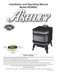
1
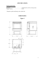
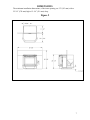
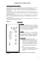
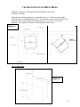
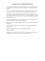
PELLET STOVE
OPERATING & INSTALLATION INSTRUCTIONS
Saranac Insert
Model
Saranac Free
Standing Model
Please read this entire manual before installation and use of this pellet fuel burning room
heater. Failure to follow these instructions could result in property damage, bodily injury or
even death.
Contact your local building officials about restrictions and installation inspection
requirements in your area.
Save these instructions.
1871 Route 9H
Hudson, NY 12534
U.S.A.
Phone: 518-828-6363
Fx:
518-828-5639
TABLE OF CONTENTS
Introduction ..................................................................................................... 3
Safety Information ..................................................................................... 4 - 5
Specifications .................................................................................................. 6
Dimensions ................................................................................................ 6 - 7
Operating Instructions.............................................................................. 8 - 11
Thermostat Installation ................................................................................. 12
Clearances to Combustibles ................................................................... 13 - 14
Installing Your Room Heater................................................................. 15 - 23
Mobile Home Installations............................................................................ 24
Insert Pellet Stove .................................................................................. 25 - 27
Vent Termination Locations ......................................................................... 28
Maintenance ........................................................................................... 29 - 32
Optional Accessories .................................................................................... 33
Troubleshooting ..................................................................................... 34 - 36
Wiring Diagram ............................................................................................ 37
Replacement Parts List ................................................................................. 38
Warranty ................................................................................................ 39 - 40
2
INTRODUCTION
Thank you for purchasing the Saranac pellet stove. The Saranac is available as an insert
or a freestanding stove. The Saranac has been tested and listed for installation in
residential, mobile homes and alcove installations.
This heater has been certified to ASTM E1509-04 Standard Specification for Room
Heaters, Pellet Fuel-Burning Type.
The performance of you pellet stove can be affected by the type of pellet fuel burnt in the
appliance. It is important to use only pellet fuel that is dry and free from dirt or other
impurities.
The Pellet Fuel Industry has established standards for wood pellet manufacturers. It is
recommended that the fuel used in this appliance meet or exceed the following
specifications:
Fines (fine particles)…….1% maximum through a 1/8" screen
Bulk Density…………….minimum 40 lbs per cubic foot
Size……………………...maximum 3/8" diameter by 1-1/2" long
Ash Content……………..1% maximum (Premium grade)
……………..3% maximum (Standard grade)
Moisture Content………..8% maximum
Heat Content…………….minimum 8,200 btu/hr
It is important to note that the ash content of the fuel (and frequency of operation)
determine the frequency of cleaning required for your unit. A high ash fuel may result in
your unit having to be cleaned daily while a low ash content fuel may permit a longer
time between cleaning.
Occasionally impurities in the fuel will cause a hard mass build up in the burn pot. This
build up may block the air flow through the burn pot affecting the performance of your
unit. Check the burn pot daily for any blockage. If necessary remove the burn pot liner
(once unit has cooled) and clean the liner and the burn pot.
Since Inca Metal has no control over the quality of pellet fuel used in this unit they
assume no responsibility for the end users choice in wood pellets.
Caution: Be sure to store the pellet fuel a minimum of 3' (0.9 m) away from the pellet
stove.
Please note that the rating label may be found on the inside of the hopper lid for the
freestanding unit and on the hopper cover for the insert.
3
SAFETY INFORMATION
Be sure to read the entire owner’s manual prior to installing and operating this pellet fuel
burning heater.
Failure to follow these instructions could result in property damage, bodily injury or even
death.
This stove’s exhaust system works with negative combustion chamber pressure and a
slight positive chimney pressure, it is extremely important to ensure that the exhaust
system be sealed and airtight. The ash pan and viewing door must be securely fastened in
order for the unit to be airtight. This appliance will not operate using natural draft or
without a power source for the blowers.
The use of grates or other methods of supporting the fuel is not permitted.
This unit is designed to burn pellet wood fuel only. Do not use any other type of fuel,
this will void any warranties stated in this manual. THE USE OF CORDWOOD IS
PROHIBTED BY LAW.
This appliance is designed for residential installation according to current national and
local building codes. It is also approved as a mobile home heater which is designed for
connection to an outside combustion air source.
It is recommended that the exhaust vent be cleaned bi-annually or after every two tons of
pellets.
Soot or creosote may accumulate when the stove is operated under incorrect conditions
such as an extremely rich burn (black tipped lazy orange flames). Do not operate the
stove if the flame becomes dark or sooty or if the burn pot overfills with pellets. Turn the
stove off and call your dealer.
The grounded electrical cord should be connected to a standard 120 volt, 60 hertz
electrical outlet. Ensure that the electrical cord is not trapped under the appliance and
that it is clear of any hot surfaces or sharp edges.
Be sure that the structural integrity of the home is maintained when passing venting
through walls, ceilings or roofs.
The ash pan and viewing door must be locked securely for proper and safe operation of
the pellet stove.
DO NOT PLACE UNBURNED OR NEW PELLET FUEL IN ASH PAN. A fire in the
ash pan may occur.
Do not abuse the glass by striking or slamming the door. Do not attempt to operate the
unit with broken glass. Replacement glass must be purchased from an Inca Metal dealer.
Do not attempt to clean the glass while unit is hot. To clean the glass, use a soft cotton
cloth and mild window cleaner, gas or woodstove cleaner.
4
SAFETY INFORMATION (continued)
Do not operate your stove if you smell smoke coming from it. Turn it off, monitor it and
call your dealer.
Repair and servicing of your stove may only be done by a qualified technician.
Disconnect the power cord before performing any maintenance or repair. NOTE:
Turning the stove to "off" does not disconnect all power from the unit.
The stove will not operate during a power outage, if this happens check for smoke
spillage and open a house window if necessary.
Keep foreign objects out of the hopper.
Contact your local building officials to obtain a permit and information on any
installation restrictions or inspection requirements in your area. Notify your insurance
company of your new stove.
Allow the stove to cool before performing any maintenance.
Ashes must be disposed of in a metal container with a tight lid and placed on a noncombustible surface well away from your home.
Check the venting system, at least twice a year, for creosote build up.
CAUTION:
DO NOT CONNECT TO ANY AIR DISTRIBUTION DUCT OR SYSTEM.
NEVER USE GASOLINE, GASOLINE TYPE LANTERN FUEL, KEROSENE,
CHARCOAL LIGHTER FLUID, OR SIMILAR LIQUIDS TO START OR
FRESHEN UP A FIRE IN THE HEATER. KEEP ALL SUCH LIQUIDS WELL
AWAY FROM THE HEATER WHILE IT IS IN USE.
HOT WHILE IN OPERATION. KEEP CHILDREN, CLOTHING AND
FURNITURE AWAY FROM THE HEATER. CONTACT MAY CAUSE SKIN
BURNS. YOUNG CHILDREN SHOULD BE SUPERVISED WHEN THEY ARE
IN THE SAME ROOM AS THE STOVE.
5
SPECIFICATIONS
Heating Specifications:
Burn Rate…………………………………*50,000 btu/hr or 4.8 lbs. of fuel per hour
Hopper Capacity………………………….50 lbs.
*Depends on quality and heating value of pellet fuel.
DIMENSIONS
Figure 1
6
DIMENSIONS
The minimum installation dimensions, of the insert opening, are 32” (813 mm) wide x
22-3/4” (578 mm) high x 12-1/4” (311 mm) deep.
Figure 2
7
OPERATING INSTRUCTIONS
Filling the Hopper
This pellet stove is available as a freestanding unit or as an insert, therefore there is a
different method of filling the hopper for each type of unit.
To open the hopper lid, on the insert, pull slightly forward and up. To open the hopper
lid on the freestanding unit simply lift up.
CAUTION: Do not overfill the hopper.
Pre-start check up
Remove the burn pot (only if unit is cool) and clean out any ash debris. Be sure to install
the burn pot in the correct position (see page 29).
The blowers and automatic fuel supply are controlled from a panel located on the right
hand side of the stove.
Note: During the first time your unit is fired it may omit an odor as high temperature
paint cures. Maintaining a smaller fire (for the first few hours) will help to minimize this.
Avoid placing any items on the stove top during this period as the unit's paint could be
permanently damaged.
Lighting Instructions
When first operating the pellet stove, switch it to manual mode, so you can have full
control of the pellet stoves control board functions and familiarize yourself with how the
pellet stove works. It is in this mode that the heat level for the AUTO and T-STAT mode
is set.
To Start up a Cold Stove
Press and release the On/Off button. The green light above the On/Off button will flash
to indicate that the start up cycle has started. The light above the Auger button will turn
on, intermittently, indicating the activation of the auger which is feeding the pellets into
the burn pot. At this time the electric igniter is activated. The igniter takes a few minutes
to heat up enough to ignite the pellets in the burn pot. This may take as little as 3 minutes
or as much as 8 minutes. If no flames appear prior to 15 minutes the stove will shut
down and will need to be turned back on again.
Once the flame has been established, the start up cycle will end, this takes between 10 15 minutes. At this point, if the stove is in the manual mode, it will default to the lowest
heat level setting. If the stove is in either the AUTO or T-STAT mode the heat output
will vary in accordance with the commands from the thermostat.
8
OPERATING INSTRUCTIONS
To Start up a Hot Stove
If the stove is warm at re-start, the On/Off button must be pressed down and held for 2
seconds or more until the Heat Level light is lit.
When first starting a new pellet stove, or when you completely empty the hopper of
pellets, you can press and hold the AUGER button to get the pellets into the burn pot
quicker. See AUGER button description on page 10.
The convection air flow will change in accordance with the heat setting. Convection air
flow is at maximum when the heat setting is at maximum. Air flow will be at a minimum
when the heat setting is at a minimum. If the user wishes to turn the convection fan on
maximum, at any heat setting, they may do so by pressing the FAN button.
If the flame goes out, or the heat output is too high on minimum heat level setting, use the
AUGER TRIM button to make adjustments. See the AUGER TRIM button description
on page 11.
To Shutdown Stove
Turn off the unit by pressing the On/Off button. The stove will enter the shutdown cycle
where the pellets will stop feeding to allow the fuel in the burn pot to be used up. The
exhaust blower and convection fan will continue to operate until the flames are out and
the unit has cooled down. Once this has been accomplished the stove will shut down
completely.
In the AUTO mode the turning the thermostat all the way down can also be used to turn
off the stove.
DO NOT TURN OFF THE UNIT BY DISCONNECTING THE ELECTRICAL
POWER TO THE UNIT. THIS WILL CAUSE THE UNIT TO MISS THE
PROPER SHUTDOWN CYCLE, CAUSING THE RELEASE OF SMOKE INTO
THE HOUSE AND OVERHEATINGOF THE STOVE.
9
OPERATING INSTRUCTIONS
Control Board Functions
AUTO/T-STAT/Manual Switch: This switch selects the pellet stove operating mode.
Slide the switch to Manual (the far right position) to be able to manually select the heat
settings and controls.
If you have a remote thermostat attached and wish to have the pellet stove controlled by
the thermostat slide the switch to T-STAT (the middle position) to operate the pellet
stove in variable heat mode. The thermostat will control the heat output of the pellet
stove alternating between the lowest heat level and the highest heat level pre-selected by
the user.
The AUTO setting (far left position) is similar to the T-STAT setting except that the
stove will alternate between shutdown (stove turned completely off) and restart to the
user selected heat level, when commanded by the thermostat. When using a thermostat
the T-STAT position is recommended. This setting provides a more even heat output, for
better comfort, and will extend the life of the ignition system components. In addition
the constant flame, in the stove, will serve as a warning for people and pets to keep away
from the stove while in operation.
After switching between modes the stove should be turned Off and back On to reset the
control to operate in that mode.
On/Off Button: This button is used to turn the unit on and off. If the stove is cold prior
to start-up press and release the On/Off button. The green light above the On/Off switch
will flash to indicate start up cycle has started. Fuel pellets will start to feed into the burn
pot. The electric ignition system will be automatically activated, flames in the burn pot
will normally appear between 3 - 7 minutes. Once the flame has been established, the
start up cycle will end, this takes between 10 -15 minutes. At this point the user will be
able to make heat level adjustments.
If the stove is warm at restart the On/Off button must be pressed down and held for 2
seconds, or more, until the minimum heat level setting light is lit.
Heat Level: When pressed this increases the heat level setting one level. Pressing the
button will cycle the heat setting from minimum to maximum and back again. The
convection fan speed will also increase with the heat level setting. When the light is
flashing during the start up cycle the heat level button will not respond to the
adjustments. When the light is solid, indicating the start up cycle is finished, it will then
respond (only in manual mode).
Fan: Use this button to override the automatic fan speed control to turn the convection
fan on high. The smart control on this pellet stove will vary the fan speed in accordance
with the heat level setting. It is recommended to let the controller automatically adjust
the speed of the fan for optimum efficiency and minimal fan noise.
Auger: Pressing and holding this button will turn on the auger to speed feeding of pellets
into the burn pot, when first using the pellet stove or when you completely empty the
hopper of pellets and restarting after reloading the hopper. You can load the auger faster
by pressing and holding this button (until you see pellets dropping into the burn pot).
This button will turn off after 1 minute and must be released and pressed again if you
want to continue to manually operate the auger.
10
OPERATING INSTRUCTIONS
Control Board Functions (continued)
Auger Trim: This is used to change the feed rate on the minimum heat level for various
quality of pellet fuel. This will help to keep the flames from extinguishing on the
minimum heat level setting. It is also used to lower heat output on the minimum heat
level setting.
Push and release the Auger Trim button until the heat level 1 and 5 lights appear. This
will slightly increase the feed rate on the minimum heat level setting to keep the burn pot
flames from going out.
Push and release the button until the heat level 1 and 4 lights appear, this will reduce the
pellet feed rate on the minimum heat level setting. Use this setting to reduce the heat
level output on low.
Push and release the button until just the heat level 1 setting light is on, this is the factory
setting and works for most types of fuel.
Figure 3
Control Panel
Open Door
If the door is opened, while the unit is operating, it
must be closed within 30 seconds or the unit will go
into vacuum error mode. If this happens, close the
door, turn the control panel switch to "OFF" then
back to the setting it was previously at.
Refueling
For maximum performance we recommend that you
do not let the hopper drop below 1/4 full. KEEP
LID CLOSED AT ALL TIMES EXCEPT WHEN
REFILLING. DO NOT OVERFILL HOPPER.
Safety Features
1. Your unit is equipped with a "high
temperature limit" thermo snap disc. This
snap disc serves to shutdown the auger in
the case of an over temperature situation
(such as convection fan failure). This disc
has a manual reset button that will have to
be reactivated once the unit has cooled
down.
2. If the combustion fan malfunctions a
vacuum switch will automatically shut down
the auger (see also Open Door section
above).
If either of these situations occur contact your dealer as a service call may be
required.
11
THERMOSTAT INSTALLATION
An optional thermostat is available for use with this unit. A thermostat can help you
maintain a constant room temperature. A milli-volt thermostat is required.
NOTE: Your thermostat should be installed by an authorized dealer or service person.
To Install Thermostat:
• Disconnect unit from power supply.
• Open right side panel to gain access to rear of control panel.
• Take the thermostat wires and connect to the green screw terminal on the rear of
the control panel (see Figure 4).
When the room cools to below the thermostat setting the stove will automatically restart
and run at the last feed rate setting. When the room is warm enough the unit will shut
off. The exhaust fan will continue to run until the stove cools.
Figure 4
screw connection for
thermostat
12
CLEARANCES TO COMBUSTIBLES
INSTALL VENT AT CLEARANCES SPECIFIED BY THE VENT
MANUFACTURER.
When the unit is being installed on a combustible floor a 1/2" thick non-combustible
hearth pad must be installed under the unit. The pad must extend at least the width of the
appliance and at least the depth of the appliance plus 6" (152 mm) in front of the
appliance. This applies for both the freestanding unit and the insert.
Figure 5
Alcove Dimensions
Figure 6
13
INSTALLING YOUR ROOM HEATER
Your first step is to decide where to install your pellet stove. In order to get the best use
of circulated heat we recommend too install it in a large open room centrally located in
the house.
Next it is very important to check that clearances to combustibles are maintained, these
can be found on page 14 of this manual and on the rating label of the pellet stove.
The pellet stove can be vented through an exterior wall or into an existing masonry or
metal chimney. The chimney must be lined if over 6” (150 mm) in diameter or if it has a
cross sectional area of over 28 square inches. Venting can pass through the ceiling and
roof if listed pipe is used.
Do not obtain combustion air from the attic, garage or any other unventilated area. You
may obtain combustion air from a ventilated crawlspace.
DO NOT INSTALL A FLUE DAMPER IN THE EXHAUST VENTING SYSTEM OF
THIS UNIT.
DO NOT CONNECT THIS UNIT TO A CHIMNEY FLUE SERVING ANOTHER
APPLIANCE.
INSTALL VENT AT CLEARANCES SPECIFIED BY THE VENT
MANUFACTURER.
This appliance is certified for use with listed “PL” or “L” pellet venting products as well
as Selkirk’s Direct-Temp Vent system for pellet burning appliances..
14
INSTALLING YOUR ROOM HEATER
HORIZONTAL EXHAUST VENT INSTALLATION
1. Locate your appliance in a location which meets the requirements of this manual
and where it does not interfere with the house framing, wiring, etc..
2. Install a non-combustible hearth pad underneath the unit. This pad should extend
at least 6” (152 mm) in front of the unit.
3. Place the stove approximately 15” (381 mm) away from the interior wall.
4. Locate the center of the exhaust pipe of your unit. This point should then be
extended to the interior wall of your house. Once you have located the center
point, on the interior wall, cut a 7” (175 mm) diameter hole through the wall.
5. The next step is to install the wall thimble, refer to the instructions which come
with the wall thimble for this step.
6. Install the appropriate length of exhaust vent pipe into the wall thimble. See step
11 when determining the correct length of exhaust vent to use.
7. Install the optional combustion air intake pipe. The unit has an option to utilize
outside air for combustion. Be sure that the outside air vent has a proper cap on it
to prevent rodents from entering and also is installed where it won’t become
blocked with snow, etc..
8. Connect the exhaust vent pipe to the exhaust outlet of your appliance.
9. Secure all vent joint connections with 3 screws. Seal the exhaust vent joint
connections with high temperature silicone sealant.
10. Push the unit straight back to the interior wall but be sure to maintain the
minimum clearances to combustibles 6” (152 mm) to the back of the unit. Seal
the annular space, of the wall thimble, around the vent pipe with high temperature
silicone sealant.
11. The exhaust vent pipe must extend at least 12” (300 mm) out past the exterior
wall. Seal the annular space, of the wall thimble, around the vent pipe with high
temperature silicone sealant.
12. Install a listed horizontal termination cap or if necessary install a 90° elbow and
appropriate length of vertical venting. A listed vertical vent cap is recommended
however (if local codes allow) when the vent terminates several feet above ground
level and there are no trees, plants, etc. within several feet a 45° elbow can be
used as a termination. The elbow must be turned down to prevent rain from
entering.
15
HORIZONTAL EXHAUST VENT INSTALLATION
(continued)
Figure 8
Figure 9
16
FREESTANDING INTERIOR VERTICAL INSTALLATION
1. Choose the location for your pellet stove, see item 1 of the Horizontal Exhaust
Vent Installation (page 16) for help in determining the correct location.
2. Install the non-combustible hearth pad.
3. Place your pellet stove on the hearth pad and locate the unit in manner that will
leave the exhaust vent with a minimum of 3” (75 mm) clearance to any
combustible wall.
4. If installing the optional air intake, Locate the center of the combustion air intake
pipe at the back of your unit. Line up the center with the same spot on your
exterior wall and cut a hole 2-1/2” (64 mm) in diameter through the wall.
5. Secure all vent joint connections with 3 screws. Seal the exhaust vent joint
connections with high temperature silicone sealant.
6. Install the combustion air intake pipe.
7. Install a tee, with a cleanout, on the exhaust pipe found at the rear of your unit.
8. Install listed vent upward through the ceiling. When you pass through the
combustible framing ensure that the appropriate ceiling is used. You must
maintain a minimum 3” (75 mm) clearance to combustibles and keep any
insulation away from the exhaust vent.
9. Extend the exhaust vent through the roof flashing and ensure that the vertical cap
is approximately 36” (900 mm) above the roof.
Figure 10
17
FREESTANDING EXTERIOR VERTICAL INSTALLATION
1. Follow steps 1 – 5 from previous page.
2. Locate the center of the exhaust pipe, at the back of the unit. Line up the center
with the same spot on the exterior wall a cut a 7” (175 mm) diameter hole through
the wall.
3. Install the wall thimble, refer to the instructions which come with the wall thimble
for this step.
4. Install a listed exhaust vent through the wall, be sure to make sure that 3” (75
mm) clearances to combustibles are maintained.
5. Secure all vent joint connections with 3 screws. Seal the exhaust vent joint
connections with high temperature silicone sealant.
6. Install a Tee with a cleanout on the end of the exhaust pipe, then install listed
venting upward from there. Be sure to install support brackets every 5’ (1500
mm) to keep the venting straight and secure.
7. Extend the exhaust vent through the roof flashing and ensure that the vertical cap
is approximately 36” (900 mm) above the roof.
Figure 11
18
SELKIRK DIRECT-TEMP VENT SYSTEM FOR PELLET
APPLIANCES
Images courtesy of Selkirk
19
SELKIRK DIRECT-TEMP VENT SYSTEM FOR PELLET
APPLIANCES
Images courtesy of Selkirk
UP & OUT HORIZONTAL TERMINATION KIT
Figure 12
20
SELKIRK DIRECT-TEMP VENT SYSTEM FOR PELLET
APPLIANCES
Images courtesy of Selkirk
STRAIGHT OUT HORIZONTAL TERMINATION KIT
Figure 13
21
SELKIRK DIRECT-TEMP VENT SYSTEM FOR PELLET
APPLIANCES
Images courtesy of Selkirk
THROUGH THE ROOF VERTICAL TERMINATION KIT
Figure 14
22
MOBILE HOME INSTALLATION
Mobile home installation should be done in accordance with the Manufactured Home and
Safety Standard (HUD), CFR 3280, Part 24.
In order for this unit to be installed in a mobile home the following criteria must be met:
• The unit must be secured to the floor using lag bolts in the holes provided in the
pedestal base.
• Ensure that the unit is permanently electrically grounded to the chassis of your
home.
IT IS MANDATORY TO TAKE THE COMBUSTION AIR FROM THE OUTSIDE
WHEN INSTALLING THIS UNIT IN AIR TIGHT OR MANUFACTURED/MOBILE
HOMES.
CAUTION:
THE STRUCTURAL INTEGRITY OF THE MANUFACTURED HOME FLOOR,
WALL, AND CEILING/ROOF MUST BE MAINTIANED.
WARNING:
DO NOT INSTALL IN SLEEPING ROOM.
Figure 15
HEARTH PAD
FLOORING
STEEL FRAME
1/4" LAG BOLTS,
SECURELY FASTENED
GROUND WIRE, DIRECTLY
TO METAL CHASSIS
NOTE: Only the freestanding model is for installation into a mobile home.
23
INSERT PELLET STOVE
The pellet stove is also available as an insert. There is a small amount of assembly
required when installing this model.
The steps are as follows:
Note: The shroud must be installed before unit is set into its final position.
Step 1: Shroud Side
Facing the back of the unit take the left shroud side piece (no control panel hole) and
fasten, as shown, with 2 screws provided.
Figure 16
Step 2: Shroud Side
Facing the back of the unit take the right shroud side piece (control panel hole) and
fasten, as shown, with 2 screws provided.
Figure 17
24
INSERT PELLET STOVE (continued)
Step 3: Shroud Top
Facing the back of the unit take the top shroud side piece and fasten, as shown, with 4
screws provided.
Figure 18
Step 4: Control Board
Take the control board and insert it from the back of the right shroud side (facing front of
unit). Fasten control board in place with 4 screws provided (top & bottom of board).
Figure 19
25
INSERT PELLET STOVE (continued)
Air Inlet
Exhaust Cap
Steel Plate or Flashing
Rigid Vent Pipe
Figure 20
Damper Removed or
Fastened Open (for
Canada) or sealed off
(United States)
Flexible Exhaust
Vent
Mantle
90º elbow or clean out Tee
Minimum 6” (150 mm) noncombustible Floor Protection
Installation into a Masonry Fireplace:
1. Have the masonry chimney inspected by a certified
chimney sweep or installer to determine its structural
condition.
2. Determine the amount of venting required to reach
the top of the chimney and then add 14” to ensure the
termination is an adequate distance above the roofline.
3. The first 5’ of your exhaust vent will be Simpson
Dura Vent pellet stove flex vent the remainder will be
rigid pipe. For each joint subtract 1-1/2” to allow for
the overlap. You may need an adjustable length
section to achieve the correct height. The air intake
may be 2” aluminum flex vent.
4. Assemble the first rigid section (of the exhaust
pipe) to the pellet stove flex vent insuring that the
“UP” arrows shown on the pipe labels are pointing up.
Push the sections together and twist to lock. Repeat
the process for the remainder of the pipe sections and
lower the assembly down the chimney. Lower the
intake and exhaust pipes below their normal position
in order to connect the to the back of the appliance. It
may be necessary to tie a line to the top section, of
venting, to pull it back up to the correct position after.
5. In order to connect to the exhaust of the stove you
will need to install a pipe adapter to the exhaust fan
and the either a 90º elbow or a clean out tee with cap.
The air intake can be attached, to the appliance, by
using a hose clamp.
6. Connect the stove to the coupling on the bottom of
the exhaust flex vent and twist to the locked position.
Push the appliance into the fireplace to its final
position. Go to the top of the chimney and pull the
vent system up to the desired height.
7. For the exhaust termination of the pellet vent use a
tall cone flashing and a storm collar. This requires
14” of pipe above the top of the masonry chimney.
Pull the pipe up through the flashing to the desired
height and mark where the storm collar will go. Slip
the storm collar down over the pipe and fasten it to the
pipe with a 1/4” stainless steel sheet metal screw. The
storm collar will then support the entire exhaust vent
system.
8. To install the air intake vent through the chimney
cap you may cut a hole and install cap as shown or
attach air intake vent to a flashing and cap. The
chimney top must be properly sealed to prevent rain
and or snow from entering the chimney.
9. Install the cap and seal around the joint of the
storm collar and any other joints that are visible.
26 installation.
10. This completes the masonry chimney
Figure 21
VENT TERMINATION LOCATIONS
Letter
A
Minimum Clearance
24" (60 cm)
B
48" (122 cm)
C
D
24" (60 cm)
24" (60 cm)
E
F
G
H
24" (60 cm)
12" (30 cm)
12" (30 cm)
3' (91 cm) within a height of 15' (4.5 m)
above the meter/regulator assembly
I
J
3' (91 cm)
12" (30 cm)
K
L
24" (60 cm)
7' (2.13 m)
Description
Above grass, top of plants wood, or any other
combustible material.
From beside/below any door or window that may be
opened.
From any door or window that may be opened.
To any adjacent building, fence and protruding parts
of the structure.
Below any eave or roof overhang.
To outside corner.
To inside corner, combustible wall.
To each side of center line extended above natural
gas or propane meter/regulator assembly or
mechanical vent.
From any forced air intake or other appliance.
Clearance to non-mechanical air supply inlet to
building, or the combustion air inlet to any appliance.
Clearance above roof line for vertical terminations.
Clearance above paved sidewalk or paved driveway
located on public property.
27
MAINTENANCE
FAILURE TO CLEAN AND MAINTAIN THIS UNIT AS INDICATED MAY
RESULT IN POOR PERFORMANCE AND HAZARDOUS SITUATIONS. NEVER
CLEAN THE UNIT WHEN HOT.
Burn Pot
Note: Let the unit cool to room temperature before inspecting the burn pot.
Inspect the burn pot regularly to check that the holes have not become plugged. If
necessary clean thoroughly. It is imperative that the burn pot be re-installed the correct
way or the unit will not light. The end of the burn pot with an igniter hole in it (see
Figure 22) must be installed facing the rear of the unit. This hole allows the igniter to
heat up the pellets to the point of ignition.
Figure 22
Igniter Hole
Figure 23
28
MAINTENANCE - continued
Ash Removal - Freestanding Unit
If left neglected ashes will eventually fill the ash pan. Remove the ashes periodically to
avoid unnecessary ash build up. Ash removal is as follows:
1. Let fire run out and unit cool to room temperature.
2. Clean the heat exchanger tubes (see Heat Exchanger Cleaning section).
3. Open the ash pan door, remove the burn pot and burn pot liner and empty into
metal container.
4. Vacuum to remove ashes from the firebox. BE SURE THAT ASHES ARE
COOL TO THE TOUCH BEFORE VACUUMING. Some regular vacuums
and shop vacs may leak ash into the room. Your vacuum or shop vac may have a
special filter or bag available to eliminate this leakage.
5. Remove ash pan and dispose of ashes into metal container.
6. Reinstall ash pan.
7. Reinstall burn pot and burn pot liner.
Ash Removal - Insert Unit
Figure 24
Ash Pan Door
1. Let the unit cool to room temperature then lift the ash pan door up and pull out.
2. Follow directions for freestanding unit on previous page.
Ash Disposal
Ashes should be placed in a metal container with a tight fitting lid. The closed ash
container should be placed on a non-combustible surface or on the ground well away
from all combustible materials, pending final disposal. If the ashes are disposed of by
burial in soil or otherwise locally dispersed, they should be retained in the closed
container until all cinders have been thoroughly cooled.
29
MAINTENANCE - continued
Cleaning
Heat Exchanger Tubes – Your unit is designed with a built in heat exchanger tube
cleaner. This should be used every 2 or 3 days to remove ash build up on the heat
exchanger tubes, which can reduce heat transfer. The handle, for the heat exchanger tube
cleaner, is located inside the firebox. Slide the rod front to back several times to clean
the tubes then follow the instructions for ash removal.
Figure 25
Fans – DANGER: RISK OF ELECTRIC SHOCK. DISCONNECT POWER BEFORE
SERVICING UNIT.
Over time ash or dust may accumulate on the blades of the convection & combustion
fans. The fans should be inspected, periodically, and if any accumulation is present
vacuumed clean as the ash or dust can impede the fans performance. It is also possible
that creosote may accumulate in the combustion fan, this must be brushed clean.
The combustion fan can be found behind the left side panel (facing the front of the unit),
the convection fan can be found behind the right side panel. To access the igniter you
must remove the air inlet tube and cover (2 screws).
Note: When cleaning be careful not to damage the fan blades.
Figure 26
30
MAINTENANCE - continued
Chimney Cleaning:
1. Creosote Formation – When wood is burned slowly it produces tar and other
organic vapors which combine with expelled moisture to form creosote. The
creosote vapors condense in the relatively cool chimney flue, as a result creosote
residue accumulates on the chimney lining. When ignited creosote makes an
extremely hot fire which can damage the chimney or cause a house fire.
2. Fly Ash – This can accumulate in the horizontal sections of a vent run. Fly ash is
non-combustible although if allowed to build up, continuously, it may impede the
exhaust flow.
3. Inspection of Vent System – The chimney/venting system should be inspected
should be inspected annually or per ton of fuel to determine if creosote or fly ash
build up has occurred. To clean the chimney, detach the vent where it attaches to
the combustion blower. If creosote has accumulated it should be removed.
Inspect the entire vent system from unit exhaust to termination. Creosote should
be removed with a brush specifically designed for the type of chimney in use. It
is recommended that a qualified service technician perform the inspection and
required maintenance.
Glass Doors:
Gaskets around the door and window panes should be inspected, cleaned and repaired
when necessary.
Door Removal and Replacement:
If glass is broken carefully remove (once unit has cooled, also be sure to wear gloves)
any loose pieces of glass from the door frame.
Task
Maintenance Schedule
Burn Pot
check daily
Combustion Chamber
weekly
Heat Exchanger Tubes
bi-weekly
Ash Pan
bi-weekly or every 10 bags of fuel
Convection Fan Blades
annually
Combustion Fan Blades
annually
Hopper
bi-weekly or every 10 bags of fuel
Venting System
annually
Glass
as needed
Gaskets
annually
31
OPTIONAL ACCESSORIES
This pellet stove is available with an optional firebox decorative liner as well as a
ceramic log set.
Decorative Liner Installation:
1. Install the center panel, be sure to line up the hole with the drop tube.
2. Install the left and right panels.
Left Panel
Right Panel
Figure 27
All Panels Installed
32
TROUBLE SHOOTING
See figure 26, page 31, for component locations.
Condition 1: The unit will not light.
• Check that the unit is plugged in and that the wall outlet has power.
• Unplug the unit then check all electrical connections against the Wiring Diagram
in this manual.
• Check the fuse on the circuit board.
• If a thermostat is used, ensure it is calling for heat.
If your unit still does not light contact your local dealer for service.
Condition 2: The stove will not operate when hot.
• Check the hopper has fuel.
• Check that the combustion air inlet is not blocked. Insufficient air supply may
cause the fire to burn cold and may cause fuel build up, in the pot, and smother
the fire.
• Check that the exhaust fan is operating, if the fan is not operating properly it may
not generate enough vacuum in the firebox.
• Check the vacuum switch by shorting out the vacuum switch then turn the control
panel to "OFF" and back to “ON”. If the unit starts to operate change the vacuum
switch.
• Check the exhaust temperature switch (located on the exhaust blower) by shorting
out the exhaust temperature switch then turn the control panel to "OFF" and back
to “ON”. If the unit starts to operate change the exhaust temperature switch.
• Check the 250°F high limit switch. This switch is manually reset, check if it has
tripped, if so let cool and reset switch. Check for cause of overheating, if switch
trips again contact your local dealer for service.
Condition 3: Exhaust blower does not operate normally.
• Check all wiring connections.
• Apply 120 volts directly to the exhaust blower, if the blower does not run replace
the blower.
Condition 4: Convection blower does not operate normally.
• Check all wiring connections.
• Apply 120 volts directly to the convection blower, if the blower does not run
replace the blower.
33
TROUBLE SHOOTING
Condition 5: Igniter will not light fuel.
• Check electrical connections (including fuse) to the igniter.
• Check the igniter tube, which touches the burn pot, is not plugged with ash. If it
is plugged remove the debris (be sure to wait until everything has cooled to room
temperature).
• Check burn pot is installed correctly (see page 29).
• If igniter still does not work, replace it.
Note: The igniter should be glowing orange when in operation.
Condition 6: The auger motor does not function normally.
• If the auger shaft does not turn but the motors armature tries to spin then this is a
sign your auger is jammed. Try to remove the blockage by poking at the fuel in
the drop tube. If this does not work then empty the hopper and remove the auger
cover and clear the blockage (Note: Before removing the auger cover
disconnect power to the unit).
• Check for voltage at the auger motor, if none check circuit board fuse.
• Ensure the exhaust blower is operating.
• Check the vacuum hose is connected or damaged.
• Bypass the vacuum switch by placing a jumper wire on the two electrical
connections. If the auger motor starts to function normally replace the vacuum
switch.
• Check the manual reset on the 250° F high limit switch. If the switch has been
tripped, check for the cause of the overheating, reset the switch and check if the
auger operates normally.
• Bypass the 250° F high switch by placing a jumper wire on the two electrical
connections. If the auger motor starts to function normally replace the high limit
switch.
• If the auger is not jammed and you have tried the other possible causes, connect
120 volts directly to the auger motor. If the auger motor does not work replace
the auger motor.
Condition 7: The 250° F high limit switch has tripped.
• Reset the switch and determine the cause. It is normally a faulty convection fan.
If the convection fan does not operate apply 120volts directly to the convection
fan, if it still does not operate replace the convection fan.
34
TROUBLE SHOOTING
Condition 8: The stove will not shut off.
• Ensure that the room thermostat (if a thermostat is used) is turned down below the
room temperature.
• Disconnect one of the wires to the exhaust temperature sensor, the unit should
then shut off.
• Turn the control board to "OFF"
If the unit will still not shut off, disconnect power to the unit and call your local dealer for
servicing.
Condition 9: The unit keeps going out on "LOW" setting.
If the unit goes out and leaves fresh unburned pellets in the burn pot liner then the fire is
going out before the unit shuts off.
• On the control panel, turn the heat level up to the next setting, poorer quality
pellets require a slightly higher setting.
Condition 10: Glass soots up at a fast rate, flame is lazy.
• The vent pipe (including air intake) may be dirty or partially blocked restricting
airflow to the unit.
• Burn pot holes are blocked. Let the unit cool and clean burn pot and burn pot
liner (be sure to follow instructions for disposal of ashes found on page 30).
• Circuit board malfunction. Time the fuel feed light at each setting (after the stove
has completed the initial "Start Up" sequence. Check the timing against the
timing chart (found below), if the auger motor runs constantly there is a problem
with the circuit board.
• Combustion blower is not operating. Check the exhaust blower is operating, if
not bypass the exhaust temperature switch, if the motor operates replace the
exhaust temperature switch. If the exhaust blower still does not work apply 120
volts directly to the exhaust blower motor, if the motor does not work replace the
exhaust blower motor.
• Poor fuel quality. The type of pellets being used may be of poor quality, if
possible try a different brand of pellets (refer to fuel type information on page 3).
Heat Position 1
Heat Position 2
Heat Position 3
Heat Position 4
Heat Position 5
Control Board Timing
Auger on 4 seconds
Auger on 6 seconds
Auger on 9 seconds
Auger on 10
seconds
Auger on 12
seconds
Auger off 12 sec
Auger off 10 sec
Auger off 9 sec
Auger off 6 sec
Auger off 4 sec
35
WIRING DIAGRAM
36
REPLACEMENT PARTS
Contact an authorized Inca Metal pellet stove dealer to obtain any of these parts. Never
use substitute materials. Use of non-approved parts can result in poor performance and
possible safety hazards as well as voiding the Warranty.
Item
Part #
control panel circuit board
DHC3000/REV-DSVH3001
auger motor
611240
250° F, normally open
high limit snap disc
X-2269F
140° F, normally open
exhaust temperature snap disc
convection fan
7021-10383
exhaust fan
7021-10384
0.1" w.c. normally open
vacuum switch
silicone tube for vacuum switch
hot rod ignitor
door gasket
door glass (front panel)
door glass (side panel)
removable door handle
brick panel set – optional
37
INCA METAL’S WARRANTY PROTECTION FOR ALL INCA
METAL PRODUCTS
Inca Metal products are designed with superior components and materials, assembled by
trained craftsmen who take great pride in their work. Once assembled the complete
fireplace is thoroughly inspected by a qualified technician, before packaging, to ensure
that you, the customer, receives the quality product that you expect from Inca Metal.
INCA METAL’S FIREPLACE’S WARRANTY
Your fireplace is guaranteed to be free of defects in materials and workmanship for a
period of 5 years from the date of purchase. This covers: combustion chambers, heat
exchangers and burners as well as stainless steel parts against tarnishing. Electrical
components and wearable parts such as blowers, thermal switches, switches, wiring,
remote controls, igniters, gaskets, and glass (thermal damage only) are covered. Inca
Metal will provide replacement parts free of charge during the first year of the limited
warranty
CONDITIONS AND LIMITATIONS
Inca Metal warrants its products against manufacturing defects to the original purchaser
only – i.e. the individual or legal entity (registered customer) whose name appears on the
original invoice – provided that the purchase was made through an authorized Inca Metal
dealer and is subject to the following conditions and limitations:
This factory warranty is nontransferable and may not be extended whatsoever by any of
our representatives.
A licensed, authorized service technician or contractor must have installed the fireplace.
Installation must be done in accordance with the installation instructions included with
the product and all local and national building and fire codes.
This limited warranty does not cover damages caused by misuse, lack of maintenance,
accident, alterations, abuse or neglect. Parts installed from other manufacturers will
nullify this warranty.
This limited warranty further does not cover any scratches, dents, corrosion or
discoloring caused by excessive heat, abrasives, chemical cleaners nor any venting
components used in the installation of the fireplace.
This warranty does not cover any problems caused to installation used venting or vent
terminations which are not certified for use with this product.
Any installation, labor, construction, transportation or other related costs or expenses
arising from defective part(s), repair or replacement or otherwise of same, will not be
covered by this warranty nor shall Inca Metal assume responsibility for same. Further,
Inca Metal will not be responsible for any incidental, indirect or consequent damages,
except as provided by law, and in no event shall they exceed the original purchase price.
38
CONDITIONS AND LIMITATIONS (continued)
In the first year only, this warranty extends to the repair or replacement of warranted
parts, which are defective in material or workmanship provided that the product has been
operated in accordance with the operation instructions and under normal conditions.
After the first year, Inca Metal may, at its discretion, fully discharge all obligations with
respect to this warranty by refunding to the original warranted purchaser the wholesale
price of any warranted but defective part(s).
Notwithstanding any provisions contained in this warranty, Inca’s responsibility under
this warranty is defined as above and it shall not in any event extend to any incidental,
consequential or indirect damages.
This warranty defines the obligations and liability of Inca Metal with respect to the Inca
Metal fireplace and any other warranties expressed or implied with respect to this
product, its components or accessories are excluded.
Inca Metal neither assumes, nor authorizes any third party to assume, on its behalf, any
other liabilities with respect to the sale of this product. Inca Metal will not be responsible
for: over firing, downdrafts, spillage caused by environmental conditions such as
rooftops, buildings, nearby trees, hills, mountains, inadequate vents, excessive venting
configurations, insufficient make up air, or negative air pressures which may or may not
be caused by mechanical systems such as exhaust fans, furnaces, clothes dryers, etc.
Any damages to fireplace, combustion chamber, brass or chrome trim or other component
due to water, weather damage, long periods of dampness, condensation, damaging
chemicals or cleaners will not be the responsibility of Inca Metal.
The bill of sale or copy will be required together with a serial number and a model
number when making any warranty claims from your authorized dealer. The warranty
registration card must be returned within 14 days to register this warranty.
Inca Metal reserves the right to have its representative inspect any product or part thereof
prior to honoring any warranty claim.
Manufactured by
Inca Metal Cutting Ltd
2771 Viscount Way
Richmond, BC
V6V 2X4
Canada
39