1
1700
ALARM
CONTROL SYSTEM
INSTALLATION
INSTRUCTIONS
This information is relevant to systems fitted
with Issue 2.7 (or later) System Software
Bona fide alarm engineers may obtain
technical support for this product from
Castle Care-Tech Ltd. on 01344 469470
1700 Alarm System Installation Instructions
Section
Page
1. Introduction . . . . . . . . . . . . . . . . . . . . . . . . . . . . . . . . . . . . . . . . . . . . . . . . . . . . . . . . . . . . 4
1.1. The Company and its Quality Statement . . . . . . . . . . . . . . . . . . . . . . . . . . . . . . . 4
1.2. The Product . . . . . . . . . . . . . . . . . . . . . . . . . . . . . . . . . . . . . . . . . . . . . . . . . . . . . . . . . . . 4
1.3. Warranty . . . . . . . . . . . . . . . . . . . . . . . . . . . . . . . . . . . . . . . . . . . . . . . . . . . . . . . . . . . . . . 4
2. The 'CE' Marking Directive . . . . . . . . . . . . . . . . . . . . . . . . . . . . . . . . . . . . . . . . . . . . 5
3. Mains Electricity . . . . . . . . . . . . . . . . . . . . . . . . . . . . . . . . . . . . . . . . . . . . . . . . . . . . . . . 5
3.1. Mains Electricity . . . . . . . . . . . . . . . . . . . . . . . . . . . . . . . . . . . . . . . . . . . . . . . . . . . . . . 5
3.2. Specifications . . . . . . . . . . . . . . . . . . . . . . . . . . . . . . . . . . . . . . . . . . . . . . . . . . . . . . . . . 5
4. Electromagnetic Compatibility . . . . . . . . . . . . . . . . . . . . . . . . . . . . . . . . . . . . . . . . . . 6
4.1. Installation Guidelines . . . . . . . . . . . . . . . . . . . . . . . . . . . . . . . . . . . . . . . . . . . . . . . . . 6
4.1.1. Siting of Equipment . . . . . . . . . . . . . . . . . . . . . . . . . . . . . . . . . . . . . . . . . . . 6
4.1.2. Mains Supply . . . . . . . . . . . . . . . . . . . . . . . . . . . . . . . . . . . . . . . . . . . . . . . . . . 6
4.1.3. Earthing . . . . . . . . . . . . . . . . . . . . . . . . . . . . . . . . . . . . . . . . . . . . . . . . . . . . . . . 6
4.1.4. Cable routing . . . . . . . . . . . . . . . . . . . . . . . . . . . . . . . . . . . . . . . . . . . . . . . . . . 6
4.1.5. AC Noise . . . . . . . . . . . . . . . . . . . . . . . . . . . . . . . . . . . . . . . . . . . . . . . . . . . . . 7
4.1.6. Severe airborne RFI from Radio Transmissions, etc. . . . . . . . . . . . . 7
4.1.7. Voltage Transients . . . . . . . . . . . . . . . . . . . . . . . . . . . . . . . . . . . . . . . . . . . . . 7
4.1.8. Electrostatic Discharge (ESD) . . . . . . . . . . . . . . . . . . . . . . . . . . . . . . . . . 7
5. The System . . . . . . . . . . . . . . . . . . . . . . . . . . . . . . . . . . . . . . . . . . . . . . . . . . . . . . . . . . . . . 8
6. Installation . . . . . . . . . . . . . . . . . . . . . . . . . . . . . . . . . . . . . . . . . . . . . . . . . . . . . . . . . . . . . 9
6.1. The End Station . . . . . . . . . . . . . . . . . . . . . . . . . . . . . . . . . . . . . . . . . . . . . . . . . . . . . . . 9
6.1.1. Mounting the Unit . . . . . . . . . . . . . . . . . . . . . . . . . . . . . . . . . . . . . . . . . . . . . 9
6.1.2. Recommended cable access to End Station . . . . . . . . . . . . . . . . . . . . . 9
6.1.3. System Paperwork . . . . . . . . . . . . . . . . . . . . . . . . . . . . . . . . . . . . . . . . . . . . . 9
6.1.4. Mains Connection . . . . . . . . . . . . . . . . . . . . . . . . . . . . . . . . . . . . . . . . . . . 10
6.1.5. Alarm Circuit Wiring . . . . . . . . . . . . . . . . . . . . . . . . . . . . . . . . . . . . . . . . 10
6.1.6. Input Wiring . . . . . . . . . . . . . . . . . . . . . . . . . . . . . . . . . . . . . . . . . . . . . . . . . 10
6.1.7. Alarm and Outputs Wiring . . . . . . . . . . . . . . . . . . . . . . . . . . . . . . . . . . . 10
6.1.8. Remote Signalling . . . . . . . . . . . . . . . . . . . . . . . . . . . . . . . . . . . . . . . . . . . 11
6.1.9. Connection of Printer . . . . . . . . . . . . . . . . . . . . . . . . . . . . . . . . . . . . . . . . 12
6.2. The Remote Keypad . . . . . . . . . . . . . . . . . . . . . . . . . . . . . . . . . . . . . . . . . . . . . . . . 13
6.2.1. Mounting the unit . . . . . . . . . . . . . . . . . . . . . . . . . . . . . . . . . . . . . . . . . . . . 13
6.3. Powering Up . . . . . . . . . . . . . . . . . . . . . . . . . . . . . . . . . . . . . . . . . . . . . . . . . . . . . . . . 14
6.4 Clean Starting the System . . . . . . . . . . . . . . . . . . . . . . . . . . . . . . . . . . . . . . . . . . . . 14
7. Wiring the System . . . . . . . . . . . . . . . . . . . . . . . . . . . . . . . . . . . . . . . . . . . . . . . . . . . . . 15
7.1. Remote Keypad wiring . . . . . . . . . . . . . . . . . . . . . . . . . . . . . . . . . . . . . . . . . . . . . . 15
7.2. Remote Keyswitch Wiring . . . . . . . . . . . . . . . . . . . . . . . . . . . . . . . . . . . . . . . . . . . 16
7.3. Outputs Wiring . . . . . . . . . . . . . . . . . . . . . . . . . . . . . . . . . . . . . . . . . . . . . . . . . . . . . . 16
7.4. Detection Wiring . . . . . . . . . . . . . . . . . . . . . . . . . . . . . . . . . . . . . . . . . . . . . . . . . . . . 17
7.4.1. An introduction to iD . . . . . . . . . . . . . . . . . . . . . . . . . . . . . . . . . . . . . . . . 17
7.4.2. Features . . . . . . . . . . . . . . . . . . . . . . . . . . . . . . . . . . . . . . . . . . . . . . . . . . . . . 17
7.4.3. Wiring . . . . . . . . . . . . . . . . . . . . . . . . . . . . . . . . . . . . . . . . . . . . . . . . . . . . . . . 18
7.4.4. Detectors . . . . . . . . . . . . . . . . . . . . . . . . . . . . . . . . . . . . . . . . . . . . . . . . . . . . 19
7.4.5. Basic Operation . . . . . . . . . . . . . . . . . . . . . . . . . . . . . . . . . . . . . . . . . . . . . 19
7.4.6. Connections . . . . . . . . . . . . . . . . . . . . . . . . . . . . . . . . . . . . . . . . . . . . . . . . . 20
7.4.7. Recommended Cable Types . . . . . . . . . . . . . . . . . . . . . . . . . . . . . . . . . . 22
7.4.8. Recommended Cable Distances . . . . . . . . . . . . . . . . . . . . . . . . . . . . . . 22
7.4.9. Connection Order for iD Biscuits . . . . . . . . . . . . . . . . . . . . . . . . . . . . 22
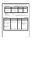
8. iD COMMISSIONING READINGS . . . . . . . . . . . . . . . . . . . . . . . . . . . . . . . . . . . 23
8.1. Table of Resistance Readings for iD system . . . . . . . . . . . . . . . . . . . . . . . . . 23
January 2000
Page 1
Castle Care-Tech Ltd.
Section
Page
9. Fault Finding iD Detection Systems . . . . . . . . . . . . . . . . . . . . . . . . . . . . . . . . . . . 24
9.1. Voltage levels . . . . . . . . . . . . . . . . . . . . . . . . . . . . . . . . . . . . . . . . . . . . . . . . . . . . . . . 24
9.2. False Alarms . . . . . . . . . . . . . . . . . . . . . . . . . . . . . . . . . . . . . . . . . . . . . . . . . . . . . . . . 24
9.3. Tamper Faults . . . . . . . . . . . . . . . . . . . . . . . . . . . . . . . . . . . . . . . . . . . . . . . . . . . . . . . 24
9.4. Checking the iD Line for Shorts . . . . . . . . . . . . . . . . . . . . . . . . . . . . . . . . . . . . . 25
9.5 Use of Test Meters . . . . . . . . . . . . . . . . . . . . . . . . . . . . . . . . . . . . . . . . . . . . . . . . . . . 25
10. Programming the System . . . . . . . . . . . . . . . . . . . . . . . . . . . . . . . . . . . . . . . . . . . . 26
10.1. Programming Options . . . . . . . . . . . . . . . . . . . . . . . . . . . . . . . . . . . . . . . . . . . . . . 26
10.1.1. Zone Programming and Zone Text . . . . . . . . . . . . . . . . . . . . . . . . . . 27
10.1.2. Set Exit Mode and Time . . . . . . . . . . . . . . . . . . . . . . . . . . . . . . . . . . . . 29
10.1.3. Set Entry Time . . . . . . . . . . . . . . . . . . . . . . . . . . . . . . . . . . . . . . . . . . . . . 29
10.1.4. Bell Duration and Bell Delay . . . . . . . . . . . . . . . . . . . . . . . . . . . . . . . 30
10.1.5. Re-Arm Count . . . . . . . . . . . . . . . . . . . . . . . . . . . . . . . . . . . . . . . . . . . . . 30
10.1.6. 'Just in Case' Timer . . . . . . . . . . . . . . . . . . . . . . . . . . . . . . . . . . . . . . . . . 30
10.1.7. Sounder Options . . . . . . . . . . . . . . . . . . . . . . . . . . . . . . . . . . . . . . . . . . . 31
10.1.8. Alarm Response in 'Part Guard' . . . . . . . . . . . . . . . . . . . . . . . . . . . . . 31
10.1.9. Assign Outputs . . . . . . . . . . . . . . . . . . . . . . . . . . . . . . . . . . . . . . . . . . . . . 32
10.1.10. System Reset . . . . . . . . . . . . . . . . . . . . . . . . . . . . . . . . . . . . . . . . . . . . . 32
10.1.11. Misoperation (Abort) Signalling . . . . . . . . . . . . . . . . . . . . . . . . . . . 33
10.1.12. Programming Access Codes . . . . . . . . . . . . . . . . . . . . . . . . . . . . . . . 33
10.1.13. Select Keypads . . . . . . . . . . . . . . . . . . . . . . . . . . . . . . . . . . . . . . . . . . . . 34
10.1.14. Inversion of Outputs . . . . . . . . . . . . . . . . . . . . . . . . . . . . . . . . . . . . . . 34
10.1.15. Keypad Alert . . . . . . . . . . . . . . . . . . . . . . . . . . . . . . . . . . . . . . . . . . . . . . 35
10.1.16. Display version . . . . . . . . . . . . . . . . . . . . . . . . . . . . . . . . . . . . . . . . . . . 35
10.1.17. View System Logs . . . . . . . . . . . . . . . . . . . . . . . . . . . . . . . . . . . . . . . . 36
10.1.18. Print Logs . . . . . . . . . . . . . . . . . . . . . . . . . . . . . . . . . . . . . . . . . . . . . . . . . 36
10.1.19. Clear Logs . . . . . . . . . . . . . . . . . . . . . . . . . . . . . . . . . . . . . . . . . . . . . . . . 37
10.1.20. Returning to User Mode . . . . . . . . . . . . . . . . . . . . . . . . . . . . . . . . . . . 37
10.2. Engineer Tests . . . . . . . . . . . . . . . . . . . . . . . . . . . . . . . . . . . . . . . . . . . . . . . . . . . . . 38
10.2.1. Output Tests . . . . . . . . . . . . . . . . . . . . . . . . . . . . . . . . . . . . . . . . . . . . . . . 38
10.2.2. Input tests . . . . . . . . . . . . . . . . . . . . . . . . . . . . . . . . . . . . . . . . . . . . . . . . . . 38
10.2.3. Walk test . . . . . . . . . . . . . . . . . . . . . . . . . . . . . . . . . . . . . . . . . . . . . . . . . . . 39
11. Notes for Guidance . . . . . . . . . . . . . . . . . . . . . . . . . . . . . . . . . . . . . . . . . . . . . . . . . . . 40
11.1. System Measurements . . . . . . . . . . . . . . . . . . . . . . . . . . . . . . . . . . . . . . . . . . . . . . 40
11.1.1. System Voltage . . . . . . . . . . . . . . . . . . . . . . . . . . . . . . . . . . . . . . . . . . . . . 40
11.1.2. Power Supply Rating . . . . . . . . . . . . . . . . . . . . . . . . . . . . . . . . . . . . . . . 40
11.1.2. System Current . . . . . . . . . . . . . . . . . . . . . . . . . . . . . . . . . . . . . . . . . . . . . 40
11.1.3. System Fusing . . . . . . . . . . . . . . . . . . . . . . . . . . . . . . . . . . . . . . . . . . . . . . 40
11.2. System Memory . . . . . . . . . . . . . . . . . . . . . . . . . . . . . . . . . . . . . . . . . . . . . . . . . . . . 40
11.3. Volume Control . . . . . . . . . . . . . . . . . . . . . . . . . . . . . . . . . . . . . . . . . . . . . . . . . . . . 41
11.4. Output options . . . . . . . . . . . . . . . . . . . . . . . . . . . . . . . . . . . . . . . . . . . . . . . . . . . . . 41
11.5. BABT Approval . . . . . . . . . . . . . . . . . . . . . . . . . . . . . . . . . . . . . . . . . . . . . . . . . . . 42
12. System Operation . . . . . . . . . . . . . . . . . . . . . . . . . . . . . . . . . . . . . . . . . . . . . . . . . . . . 43
12.1. Using the System - Summary . . . . . . . . . . . . . . . . . . . . . . . . . . . . . . . . . . . . . . . 43
12.1.1. Setting the System . . . . . . . . . . . . . . . . . . . . . . . . . . . . . . . . . . . . . . . . . . 43
12.1.2. Unsetting the System . . . . . . . . . . . . . . . . . . . . . . . . . . . . . . . . . . . . . . . 43
12.1.3. Silencing an Alarm . . . . . . . . . . . . . . . . . . . . . . . . . . . . . . . . . . . . . . . . 43
12.2. Keypad Alerts . . . . . . . . . . . . . . . . . . . . . . . . . . . . . . . . . . . . . . . . . . . . . . . . . . . . . 43
Page 2
Issue: 4a
1700 Alarm System Installation Instructions
Section
Page
13. Manager Functions . . . . . . . . . . . . . . . . . . . . . . . . . . . . . . . . . . . . . . . . . . . . . . . . . . . 44
13.1. Changing Codes . . . . . . . . . . . . . . . . . . . . . . . . . . . . . . . . . . . . . . . . . . . . . . . . . . . . 44
13.2. Testing the System . . . . . . . . . . . . . . . . . . . . . . . . . . . . . . . . . . . . . . . . . . . . . . . . . 44
13.3. Display System Logs . . . . . . . . . . . . . . . . . . . . . . . . . . . . . . . . . . . . . . . . . . . . . . . 44
13.4. Print System Logs . . . . . . . . . . . . . . . . . . . . . . . . . . . . . . . . . . . . . . . . . . . . . . . . . . 44
14. System Specifications . . . . . . . . . . . . . . . . . . . . . . . . . . . . . . . . . . . . . . . . . . . . . . . . . 45
15. Accessories for the 1700 . . . . . . . . . . . . . . . . . . . . . . . . . . . . . . . . . . . . . . . . . . . . . . 46
16. Printed Circuit Boards . . . . . . . . . . . . . . . . . . . . . . . . . . . . . . . . . . . . . . . . . . . . . . . 47
16.1. The 1700 Keypad . . . . . . . . . . . . . . . . . . . . . . . . . . . . . . . . . . . . . . . . . . . . . . . . . 47
16.2. The 1700 Control Printed Circuit Board . . . . . . . . . . . . . . . . . . . . . . . . . . 47
Appendix A: Summary of Programming commands . . . . . . . . . . . . . . . . . . . . . . 48
Options Programming Schedule . . . . . . . . . . . . . . . . . . . . . . . . . . . . . . . . . . . . . . Loose
NOTES:
1700 Systems fitted with Issue 1 printed Circuit Boards, and
Software issues prior to 2.0, are NOT compatible with LCD (English
Text) keypads (CT1030).
Castle Care-Tech Ltd. reserves the right to adjust the specifications
of this system at any time in the interests of product improvement.
Castle Care-Tech Ltd. is a permitted user of iD
Castle Care-Tech Ltd. cannot be held responsible for problems
arising from failure to follow the specifications shown in this
manual.
January 2000
Page 3
Castle Care-Tech Ltd.
1.
Introduction
1.1 The Company and its Quality Statement
Castle Care-Tech Ltd. is an independent British Company, established in 1973,
specialising in the design and manufacture of security control equipment.
Our Quality Assurance procedures are approved to British Standard BS.EN.ISO.9002,
and are rigidly applied in all aspects of production and service of all products.
1.2 The Product
The Care-Tech 1700 Alarm Control system has been designed and manufactured to
provide the facilities required by British Standard BS.4737, to form the heart of a
comprehensive alarm system.
A wide range of facilities is available, which should be programmed as described in
this manual, to meet the requirements of the individual site. Additional information is
provided in the accompanying Operating Instructions, alternative issues are provided
to suit the different display types, the appropriate one should be provided to the user
on commissioning the system.
1.2.1 Main Features
Suitable for all alarm systems, includes remote (police call) signalling triggers.
Accepts any standard (12v powered) detector, interfaced by 'iD' detection techniques.
20 detection zones.
Operated by system keypad (up to three supported), or optional keyswitch.
Castle Care-Tech Ltd. reserves the right to adjust the specifications of this
system, in the interests of product improvement.
Castle Care-Tech Ltd. is a permitted user of iD
1.3 Warranty
The product should operate successfully for many years, if installed and maintained
correctly. However, should a fault develop within 18 months of purchase, Castle
Care-Tech Ltd. undertake to repair, or replace, the product at our discretion, free of
all charges. Such items should be returned to the factory for attention.
Should investigation show that the fault was caused by operating the system outside
of its specification, by physical damage, or by unauthorised modifications, we reserve
the right to raise an appropriate charge.
Outside of the warranty period, goods returned for repair will be charged at the rate
shown in the current price list.
Products returned for repair should be suitably packed to prevent damage (including
damage from electrostatic discharges), and be accompanied by full details of the
fault, and of any additional work required.
Page 4
Issue: 4a
1700 Alarm System Installation Instructions
2
Marking Directive
This product complies with the requirements of the EMC Directive (89/336/EC) and
the Low Voltage Directive (73/23/EC and 93/68/EC)
An alarm installation built around this product will be considered compliant with the
requirements of the EMC Directive, PROVIDED THAT all other equipment used carries
the 'CE' mark, AND that the installation follows the guidelines specified in this
manual.
Mains installation MUST be performed by a qualified electrician in acordance with the
Electrical Wiring Regulations (BS.7671)
Paper must NOT be left loose in the housing in such way that it could constitute a
fire hazard.
3
Mains Electricity
IT IS OF VITAL IMPORTANCE THAT YOU READ THE FOLLOWING:
3.1 Mains Electricity
MAINS ELECTRICITY
IS DANGEROUS !
a.
b.
Mains wiring MUST be installed by a competent electrician.
Remove all mains power BEFORE removing panel lid and working on the
equipment.
The system MUST be connected to a good, clean, EARTH.
The lid MUST be connected to the mains earth terminal by the wiring loom
provided before being secured in position.
The pcb 'Gd' terminal is NOT a safety earth connection, but is for filtering
applications, - see 4.1.5
c.
d.
e.
3.2
Specifications
Mains input:
Nominal 230 to 240v AC
Max current:
150mA, Fused at 250mA
January 2000
Page 5
Castle Care-Tech Ltd.
4
Electromagnetic Compatibility
Whilst this product has been designed to meet, or exceed, all relevant emission and
susceptibility standards, this cannot guarantee that no compatibility problems will be
experienced, especially with older equipment not designed to the same standards.
Additionally, exceptional environments can produce unpredictable results. Should
problems be experienced, the other equipment should also be checked. Re-siting of
the alarm control or other equipment may be the only solution to the problem.
Further information concerning EMC is available in the BSIA publication "EMC
Guidelines for Installers of Security Systems."
4.1
4.1.1
Installation Guidelines
Siting of Equipment
Avoid locating control equipment, or detectors, close to equipment which switches
high currents, or uses radio frequencies in its operation.
4.1.2
Mains Supply
Avoid using mains supplies contaminated by interference generated by switching,
arcing, etc. If practical, wire direct from the consumer unit, rather than from a lighting
circuit, or, especially, a ring main. If a clean supply is not available, consider fitting a
suitable mains filter (IS1000) and transient suppressors.
4.1.3
Earthing
It is essential that the system is connected to a good, clean, earth. A poor earth can
induce interference into the system.
The earth connection to the lid of the metal housing is mandatory.
4.1.4
Cable routing
It is essential that cable types and maximum lengths specified in this manual are
adhered to, and that connections are terminated correctly.
Cable routes should be selected to avoid possible sources of interference. NEVER run
alarm cables close and parallel to mains cables, where it is necessary to cross such,
do so at right angles. Avoid running cables close to fluorescent lighting, electrical
switchgear, etc.
Data cables, ie those connecting keypads or iD detectors, should not be routed with
each other, or with connections to loudspeakers, telephone wiring, etc. unless they
are screened and correctly terminated.
Cable screens should be terminated at the End Station end only. For best results, the
termination should be made to the metalwork immediately at the point of cable entry
into the housing, with a 'pigtail' not exceeding 5cm.
Cables should NOT be looped inside the housing across or underneath the pcb.
Mains cable should enter the housing through the entry hole adjacent to the mains
termination point, and be terminated immediately.
Page 6
Issue: 4a
1700 Alarm System Installation Instructions
4.1.5
AC Noise
After installing cables, measure the AC voltage between mains earth and 12v supply.
If more than 1v is measured, AC Noise filters should be brought into operation by
connection of the pcb 'Gd' terminal to mains earth.
4.1.6
Severe airborne RFI from Radio Transmissions, etc.
May be attenuated by using screened cable. Alternatively, the use of the AC Noise
filters described above may help.
4.1.7
Voltage Transients
Very high voltage transients may be induced into a system from lightning, industrial
equipment, etc.; either via the mains or directly into alarm cables. The more serious
effects are almost always mains-borne. This may be minimised by the addition of a
set of transient suppression devices (IS1020) fitted to the mains input.
4.1.8
Electrostatic Discharge (ESD)
Care should be taken to avoid handling the product unnecessarily. The resistance to
damage from ESD is enhanced by the connection of pcb 'Gd' connection to mains
earth.
In areas of high static risk (eg large carpeted areas), earth yourself by touching the
panel fixing screw before working on the unit.
Loose printed circuit boards should be stored in anti-static packaging.
January 2000
Page 7
Castle Care-Tech Ltd.
5
The System
The Care-Tech 1700 consists of an 'End Station' with blank lid, controlled from
Remote Keypads (up to three) or optional remote keyswitch. The system is able to
communicate with up to 20 'iD
iD' detection devices. For details of the 'iD
iD' system, refer
7.4.
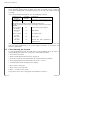
Two versions of the Keypad are available:
Cat: CT1030
Cat: CT1000
Liquid Crystal Display
7-Segment Display
Display shows two lines of English text
Display shows two characters of coded
information
The keypad includes 10 numeric digits used for entering codes, etc.
The ABCD keys are used in 'Simple setting' the system. These functions are available
on alternative keys if older style keypads without letter keys are used on the system.
The * (NO) and # (YES) keys are used in selecting choices whilst programming, and in
confirming code entry.
NOTE: The LCD Keypad is NOT compatible with 1700 End Stations of pcb
Issue 1, fitted with software issue 1.0
It is NOT possible to upgrade the software on such End Stations.
The keyswitch (if fitted) provides alternative means to set and unset the control. It is
possible to set the control from keypad and unset with keyswitch, and vice versa.
Page 8
Issue: 4a
1700 Alarm System Installation Instructions
6
6.1
6.1.1
Installation
The End Station
Mounting the Unit
Remove the four fixing screws from the front cover and lift off the panel front.
Decide on the form of cable entry to be used, and remove the appropriate knockouts,
keeping at least 5 mm clearances between alarm and telecom cables, and at least
25 mm clearances from mains cables. See 6.1.2 for recommended cable routing into
the End Station.
Mount the panel chassis, initially by the top, slotted, screw hole only, then mark the
positions of the other fixing holes and complete the mounting.
Do not drill for fixings through the holes in the chassis. Resulting dust and swarf
could result in damage to the panel, and may invalidate warranty.
Before replacing the lid, check that the fuse covers are correctly in place, that the
tamper switch arm is correctly adjusted, and ensure that the battery is clear of the lid
fixing screws, to avoid the battery being punctured. It is mandatory that the lid is
electrically connected to mains earth by the wiring loom provided.
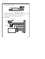
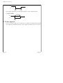
6.1.2
Recommended cable access to End Station
Keypad
Zones
Outputs
To
Digi
Digicom
(below)
Mains
6.1.3
System Paperwork
System paperwork must NOT be left loose in the housing in such a way that it could
constitute a fire hazard.
January 2000
Page 9
Castle Care-Tech Ltd.
6.1.4 Mains Connection
Mains connection should be made by a qualified electrician, in accordance with the
Electrical Wiring Regulations (BS.7671).
A good, clean, EARTH connection is essential to avoid interference being injected into
the system. The earth connection to the lid of the housing is mandatory.
NOTE:
The pcb 'Gd' connection is NOT a safety earth connection, but is provided
for filtering purposes, as described at 4.1.5
6.1.5 Alarm Circuit Wiring
The 1700 system uses iD point detection techniques for up to 20 points. For details
of iD point wiring, etc. refer section 7.4. Care should be taken in siting detectors, and
in selecting the best possible cable runs, to avoid potential sources of interference.
6.1.6 Input Wiring
KEYSWITCH
Terminals are provided for the connection of a remote
keyswitch (see 7.2)
PTS
Accepts a momentary 0v signal from a push button
(normally located immediately outside the final exit door)
to terminate exit time and complete the setting procedure.
SABT
Input for Tamper return from SAB. Remove the factory link
to 0v and wire to return of HO- from SAB
NOTE: These inputs are designed for -ive (0v) connections - wiring to +12v supply
could result in damage.
6.1.7
Alarm and Outputs Wiring
Output
Function
Rating
12v
Supply to detectors, etc.
Fused (+) 800mA
HOLD OFF
Supply to SAB
Fused (-) 500mA
BELL **
Transistor driven 0v output to
feed sounder, via SAB
Max 800mA *
STROBE
Transistor driven 0v output to
feed Strobe (wire to HO+)
Max 800mA *
SPKR
Transistor driven output to feed
loudspeaker.
Max
two
16
ohm
speakers in parallel *
OUT 1 and 2
Programmable transistor driven
outputs (see 10.1.9)
Max 65mA *
D'COM **
Connector for addition of Digital
Communicator
See 6.1.7
PRINTER
Connector for printer
See 6.1.8
* - Individual maximum, total load MUST be within system capacity (see 14).
** - These outputs may be inverted - see 10.1.14
Page 10
Issue: 4a
1700 Alarm System Installation Instructions
6.1.8
Remote Signalling
A connector on the End Station pcb enables a communicating device to be wired. This
is done by means of a loom (cat. CT.1105). The connections are as follows:
PIN
Loom Colour
Application
1
BROWN
Line Sense Input (+) from Communicator
2
RED
NOT USED
3
ORANGE
+12v supply to Communicator
4
YELLOW
Trouble output (see 6.1.8.1
5
GREEN
Fire / Aux output
6
BLUE
Confirmation (see 6.1.8.2)
7
MAUVE
Intruder output
8
GREY
PA output
9
WHITE
0v supply to Communicator
10
BLACK
Set/Unset output OR Abort output (see 6.1.8.3)
These connections provide +5v outputs, which may not trigger certain
communicators designed for +12v signals only, for which purpose, the 'DCIF'
interface is available (see section 14). The outputs may be inverted (see 10.1.14)
Incorrect connection of this loom could result in damage to the equipment.
6.1.8.1 Trouble Output
This output will be triggered by:
Engineer Access
Tamper alarm in 'DAY' mode
Set with (manual) omissions - with SET output live as well.
6.1.8.2
Sequential Confirmation Output
A 'sequential confirmation' output is available, and functions as follows:
a) the output is inhibited for 90 seconds after the system has set, and after the
creation of an alarm on entry.
b) The output will trigger when a further zone* goes into fault condition following
the end of the inhibit period.
c) The output will trigger at the second zone* trigger following a rearm.
d) The output will reset at the next code entry.
* - applicable to 'Intruder,' '24 Hour Tamper,' and 'Walk Through' zone types only,
except that a 'Walk Through' zone will NOT trigger a confirmation signal if an 'Entry
Exit' zone has previously been triggered.
It is essential that the system installation complies with the requirements of DD243
(NACP14) if this facility is to be used. The 1700 cannot be programmed to signal
'confirmation' from individually selected zones only.
January 2000
Page 11
Castle Care-Tech Ltd.
6.1.8.3
Misoperation (Abort) Signalling
Misoperation (abort) signalling is available by removal of the Code 3 intruder signal, in
conjunction with Set/Unset signalling.
Alternatively, a choice may be made between this and exception reporting of 'abort'
without Set/Unset signalling.
In either case, the abort signal is generated when the system is unset following an
alarm which has generated a code 3 'Intruder' signal.
Refer 10.1.11 for details.
6.1.8.4 Connection of Digital Communicator
A suitable Digital Communicator may be wired to the 1700 control, using a 'GP' Loom
(CAT: CT.1105). This must be plugged on with pin 1 (BROWN) connection towards the
TOP of the pcb.
NOTE: If the End Station is ordered in the 'small' housing, the SCANTRONIC 8440
'Mini-Com' will fit below the 1000 pcb within the panel, other communicators require
the use of the standard, larger, housing, or mounting externally. If mounted externally,
a buffered interface, such as the 'DCIF' module should be used (see section 14)
6.1.8.5 Red Care 'STU' Connection
The Digital Communicator outputs are compatible with the stand-alone 'EURO-STU.'
The STU PROM should be programmed for CODE 1 for all channels EXCEPT channel 4,
which should be programmed for CODE 3. If mounted externally, a buffered
interface, such as the 'DCIF' module should be used (see section 14)
6.1.9
Connection of Printer
The printer, of standard IBM PC-compatible 'Centronics' parallel type (eg Datec
DP1014.0400K, Seiko DPU40, Epson P40, etc.) should be connected to the 'PRINTER'
port on the End Station, using the correct cable (Part No. CT5400 or CT5500) by the
installing engineer, connecting the BROWN wire to PIN 1 of the connector (ie towards
the bottom of the pcb).
The printer, or its associated loom should NOT be left connected to the system when
'off line' or not in use.
Due to the wide variety of software driving requirements, it is NOT possible for the
1700 to correctly drive all types of printer, or for Castle Care-Tech to advise on
correct printer 'dip switch' settings, etc.
Page 12
Issue: 4a
1700 Alarm System Installation Instructions
6.2
6.2.1
The Remote Keypad
Mounting the unit
Open the hinged cover on the front of the housing, and remove the single fixing screw
at the right hand side of the unit. The complete front of the unit may now be removed
by sliding slightly to the right and lifting.
BEFORE MOUNTING THE HOUSING ON THE WALL, note that the rear of the housing
includes a lug designed to bear onto the tamper switch mounted on the printed
circuit board. View housing from rear, and adjust as follows:
Fixings
Tamper Lug
Screw
Cable, etc. access
Break plastic
Note that the tamper lug is anchored by a small flash of plastic at the lower end; this
should be broken by gentle pressure whilst the unit is dismantled, to permit the lug
to be pressed against the switch inside the housing
The height of the screw fitted to this lug should be adjusted to ensure that the switch
is correctly depressed against a hard surface when the unit is secured to the wall.
Any wallpaper, etc. should be removed from the point at which the screw bears.
The back of the unit should be mounted in a suitable location, on a smooth surface,
and the unit wired (and address coded) before reassembling (see 7.1). Mounting on a
rough surface may result in the cover lifting from the back.
Before the keypads can report tampers, they must be enabled in software (see
10.1.12)
NOTE: Wiring between keypad and control unit should NOT exceed 100 metres. Nor
should the cable used include cores used for other functions, especially connections
to bells, loudspeakers, etc., or be run close and parallel to mains, telephone, etc.
wiring. Wiring connections for 12v supply can usefully be doubled up - other
connections must NOT be so treated.
After installation, the protective film covering the window of the Liquid Display (LCD)
version should be removed or legibility may be impaired.
January 2000
Page 13
Castle Care-Tech Ltd.
6.3
Powering Up
Power should be applied from the Mains first, then the standby battery connected.
The standard housing will accommodate batteries up to 7AHr, the small housing up
to 2.8AHr.
After a short initialisation sequence, the control display will show
Liquid Crystal
Display
7-segment
Display
System Ready
(* / #)
d
Significance
'day' mode - system ready for use
If an alarm tone sounds, it may be silenced with 1234#
If a fault is present on the system, the display will show one of the
following:
First to Alarm
Sys tamper
F1
System (SAB or Box) Tamper
Mains Fail
(* / #)
F2
Mains Failure
First to Alarm
Lo volts
F3
Low voltage fault
Batt fault
(* / #)
F4
Battery fault
Line fault
(* / #)
F5
Telecom line fault signalled by
communicator
NB If the system is operated without a standby battery fitted, it is possible that the
SAB may trigger momentarily at 30 second (approx.) intervals, as the battery test
function is performed.
6.4
Clean Starting the System
To clear all information from the NVM prior to reprogramming (eg in the event of
reprogramming the system after a 'take-over,') follow this procedure:
1. Power the system down
2. Remove 'NVM' chip (located as shown on page 47)
3. Power the system up. This will initialise the system with factory defaults
4. Enter programming mode with default code (1111) - see 10.1
5. Carefully replace NVM, ensuring correct polarity.
6. Key in 80# (ie 'Clear logs')
7. Key in 83# (ie 'Clear zone text')
8. Press '*' to return to 'day' mode
The system is now ready to reprogram as described in section 10.
Page 14
Issue: 4a
1700 Alarm System Installation Instructions
7
Wiring the System
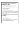
7.1 Remote Keypad wiring
Rx C Tx SP PTS - +
12v
Keypad
Push to Set Button (Duplicates
facility on
End Station)
SP
LCD
*** 7-S
C
Control pcb
***
Rx
NOTE: Tx Wiring is shown for a
Liquid Crystal Display Keypad.
7-Segment Display Keypads
wire 'Tx' to terminal labelled
'7-S'
12v
-
+
Additional keypads wire in parallel.
KEYPAD ADDRESS CODING
Each Keypad must be address coded by having ONE of the coding switches on the
Keypad pcb closed, and each be coded to a different address (starting at 1), or the
housing tamper circuit will not be functional.
RECOMMENDED CABLE TYPES FOR KEYPAD WIRING:
Up to 10 metres
6-core alarm cable
10 to 50 metres
8-core cable. Additional cores should be used to
'double-up' supply connections.
50 to 75 metres
8-core (double up supply connections as above)
SCREENED cable.
The 1700 system is NOT suitable for installations requiring the keypad to be
mounted in excess of 75 metres. For such situations, the MERiDIAN, or 2500
system should be used.
NOTE: Additional cores in the same cable should NOT be used for other
signals, especially speaker feeds, nor should the cable be run close to
telephone or mains wiring.
January 2000
Page 15
Castle Care-Tech Ltd.
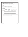
7.2
Remote Keyswitch Wiring
A remote keyswitch may be fitted the system, and wired to the 'Keyswitch' terminals
on the End Station pcb as follows:
Keyswitch
Black
Gd AC C F P
KEYSWITCH
F
P
10K resistor fitted between
'Full' and 'Part' contacts on keyswitch
It is essential that the resistor (supplied fitted direct to terminals) is fitted as shown,
as this provides tamper protection for the keyswitch connections.
Removal of this resistor from the terminals without fitting a keyswitch, or failure to
fit the resistor at the keyswitch, will initiate a system tamper alarm.
The keyswitch may be used interchangeably with the keypad(s).
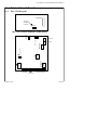
7.3 Outputs Wiring
'Push to Set' button
To 0v
To +12v
Load
PTS
OUT 1
To +12v
Load
OUT 2
SPKR
1 or 2 16 ohm
loudspeakers
wired in parallel
0v feed to Strobe
BELL -ive Tamper Return
'Hold Off' connections
SAB MODULE
12v
Supply
Page 16
STR -
0v feed to Bell
SABT
HO
+
+
12V
Issue: 4a
1700 Alarm System Installation Instructions
7.4 Detection Wiring
7.4.1 An introduction to iD
The iD (intelligent device) is not a detection device, but a means of interfacing
detection devices to the control panel to provide a simple means of detector
identification with very simple wiring. Two cores only are required for the monitoring
of up to 20 detection devices, along with supply connections for detectors requiring
power - thus greatly simplifying wiring.
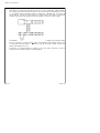
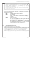
The interface device, consists of a silicon microchip packaged ready for use in a
plastic 'biscuit' such as is illustrated below, note that each device is numbered, and
that numbers should never be duplicated within a single system.
7.4.2 Features
1. Each device has its own identification number, from 01 to 30, which enables it to
be individually controlled and identified. The 1700 will accept devices of any
number up to its maximum capacity.
2. Each device continuously sends out two signals:
a) A diagnostic signal, showing that the iD device is correctly connected
and working.
b) A signal reporting the status of the internal sensor contained in the iD
device.
3. The status of the iD device may be changed by an electrical switch - such as a
Passive Infra Red detector:
January 2000
Page 17
Castle Care-Tech Ltd.
7.4.3 Wiring
Each device is connected in parallel across the two wire sensing line, which supplies
the voltage from which the devices operate. The connections are identified as L+ and
L-. Any parallel wiring configuration may be employed - including star, T and ring (as
shown below) - so long as correct polarity of connection of each device is observed!
Separate connections are required for power supply to detectors, such as PIRs.
The number of devices which may be connected per cable length is governed by ohms
law. For standard 7 strand 0.2mm2 cable, the maximum cable length between the
Control Panel and the furthest
iD device, with all 20 biscuits fitted, is120m. For
longer cable lengths, see 7.4.7.
In practice, it would probably be simpler to spur off cables from the Control to
connect devices in different parts of the building.
Page 18
Issue: 4a
1700 Alarm System Installation Instructions
7.4.4 Detectors
Detector manufacturers supply products which are directly iD compatible, either by
containing a special socket for an iD device to be plugged into, or by having the
device built in - and carrying the appropriate iD device number. Alternatively any
standard detector may be used, with an appropriate iD device wired into the
terminals.
iD devices may be connected to the Control in any order, but it is essential that
device numbers are NOT duplicated.
Devices used for 'Walk Through' zones should be numbered immediately higher
than the Final Exit-Entry zone to which it refers.
It is ESSENTIAL that iD detection cabling, along with Keypad data cables are kept
separate from any cables carrying mains, loudspeaker signals, telephone wiring, etc.
to avoid disturbance to the detector scanning routines.
It is essential that detectors are not located more than 1 metre from the interfacing
biscuit.
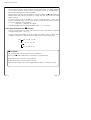
7.4.5
Basic Operation
Figure 1 shows the block diagram of an iD device connected to the sensing lines, and
incorporating a tamper switch and a set of alarm contacts. These switches are
identical to those found in any standard normally closed detector.
If the tamper switch opens, the device is disconnected from the line, and a tamper
condition is initiated at the Control. If the alarm contacts open, the status of the
internal sensor changes, this is recognised at the Control and signalled accordingly.
January 2000
Page 19
Castle Care-Tech Ltd.
7.4.6 Connections
Absolute parallel wiring makes iD installation easy, quick, neat, and cost effective.
Figure 2 shows an iD 'WIRED' biscuit, designed for direct connection into the
terminal block of any detector.
Connections using standard
L+
LSupply
Switch wire
4-core cable are simply colour to colour:
(Yellow)
to YELLOW
(Blue)
to BLUE
(for detectors)
to RED and BLACK
(white)
to detector, as shown above.
Figure 3 shows the connection of a wired biscuit to a typical PIR detector. Note the
use of the PIR terminals as a junction box for the cables - that from the left of the
diagram coming from the Control, and that to the right going on to the next detector.
On completion of wiring, the biscuit should be positioned neatly against the terminal
block or cable form, ensuring that it does not obstruct any moving parts (eg tamper
switch) or the operation of the sensor in the detector, or cause a short circuit.
Note that the iD biscuit may be concealed within a junction box, whilst providing
tamper protection should the cover be removed
Remember the simple rule: JUST CONNECT COLOUR TO COLOUR.
Page 20
Issue: 4a
1700 Alarm System Installation Instructions
NOTE: For maximum effectiveness of the system, the iD
biscuit mustbe mounted in the detector, or directly
connected to its terminals.
If this is impossible, an iD 'DP' junction box should be
used for the connection.
In the event of difficulty making connections, or housing the biscuits, special iD
junction boxes are available:
7.4.7
iD 'T'
For simple cable extension, or 'T' junctions
iD 'IL'
Now OBSOLETE
Accepts a plug-in biscuit, provides interface from biscuit to
double pole circuit, BUT can only be used immediately adjacent
to detector..
iD 'DP'
Requires a 12v supply.
New type accepts WIRED biscuit and provides double pole
circuit, including fully identified tamper loop, and which can be
used with no restriction on location.
NB. Original type, now OBSOLETE accepts a plug-in biscuit.
Provides a full double pole circuit, neither of which is identified
as a tamper circuit. Suitable only for 24 Hr tamper circuits and
similar, eg window foil, multiple 24 Hr fire doors, etc.
.
Recommended Cable Types
SCREENED cable should be used for all iD installations.
Be sure to maintain the screen conductor through detectors and junction boxes in the
wiring. The screen should be terminated to the metalwork of the End Station as close
as possible to the point of entry. Terminal blocks are provided for this purpose.
Avoid running iD cables close to other cables carrying AC or digital signals.
Do NOT use highly capacitive cable types, such as 'PYRO' or very heavy gauge cables.
January 2000
Page 21
Castle Care-Tech Ltd.
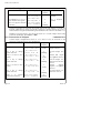
7.4.8 Recommended Cable Distances
In normal circumstances, using standard screened alarm cable, a maximum distance
of 100 metres between the End Station and furthest biscuit is recommended to
maintain optimum operation of the signalling.
Where practical, the End Station should be located to minimise iD cable distances.
Multiple short cable runs are preferable to a single long one, even if the total cable
length is greater.
To check voltage levels of the iD line, connect a DVM between L+ and L- at the
furthest point in the wiring, set the system in 'Slow Scan' mode and note the readings.
For correct operation, these should be:
2.8 (Reset), 6.5 (Mid) and 11.0 (High).
The Mid and High voltage readings should be within +0, -0.5v tolerance.
7.4.9 Connection Order for iD Biscuits
There is no restriction as to which order biscuits are wired (other than the allocation
of Walk Through zones - see 10.1.1)
However, when fault finding, it will be found very useful to have a simple chart
available to identify the connection order actually used on each wiring spur, eg
CP
01 10 05 14 08
09
02
07 12 04
15 13 06 03 11
iD
REMINDERS:
Use screened cable, with the screen correctly terminated.
Do NOT run iD cables with mains, or with other AC or digital signal
Ensure all biscuits are wired to correct polarity
Ensure that biscuits are located AT the detector.
Allocate Walk Through zones as next higher biscuit number to its Entry Exit zone.
Page 22
Issue: 4a
1700 Alarm System Installation Instructions
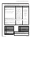
8
iD COMMISSIONING READINGS
The commissioning readings for detection circuits stipulated in BS4737 are not
directly appropriate to an iD system. The following procedure is recommended to
provide the equivalent measurements expected:
1.
2.
Complete the installation, but do not secure the detector housings
Remove the Yellow and Blue iD wires from the End Station, and twist them
together.
Power the system up, and silence any tamper alarms (using 1234#)
On each separate wiring leg, measure and record the following readings at
each detector:
a) The resistance between the iD + and - (Yellow and Blue) wires. This is
the WIRING resistance and is dependent solely on the length of cable run
and cable gauge.
Ensure reading is correct for amount of cable used.
3.
4.
NOTE 100 metres of standard alarm cable should measure approx 16 ohms.
b) The supply voltage to the detector (if applicable)
Secure the detector housing, ensuring that the tamper switch is correctly
closed.
6.
Move to the next detector and repeat the above measurements.
7.
Untwist the Yellow and Blue wires at the End Station. Measure and record
the resistance between them. This is the system iD resistance reading, and
should agree broadly with the table at 8.1.
8.
Measure for Earth or Voltage leakage to either of the iD wires, and
eliminate any such that are indicated.
9.
Replace the yellow and blue wires in the terminals
10.
Carry out normal system Walk Test, etc.
NOTE that all of the above measurements are made with wiring still in place at all
detectors, and with power applied. The presence of the iD biscuits will not affect
the readings.
5.
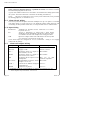
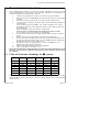
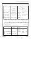
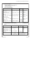
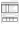
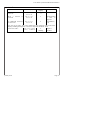
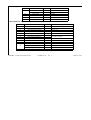
8.1 Table of Resistance Readings for iD system
No. of
biscuits
Typical
resistance
No. of
biscuits
Typical
resistance
No. of
biscuits
Typical
resistance
1
87K
8
10.9K
15
5.8K
2
43.5K
9
9.7K
16
5.4K
3
29K
10
8.7K
17
5.1K
4
21.8K
11
7.9K
18
4.8K
5
17.4K
12
7.3K
19
4.6K
6
14.7K
13
6.7K
20
4.4K
7
12.5K
14
6.2K
These readings will vary due to component tolerances, but should fall between the
adjacent values, and are provided as a guide to wiring integrity, NOT for identifying
faulty biscuits.
January 2000
Page 23
Castle Care-Tech Ltd.
9
Fault Finding iD Detection Systems
9.1
Voltage levels
To check voltage levels of the system, connect a DVM between L+ and L- terminals,
set the system in 'SLOW SCAN' mode (78# from Engineer menu), and note the
readings. For correct operation, the voltages should be:
2.8 (Reset), 6.5 (Mid) and 11.0 (High).
For the Med and High readings, +0, -0.5v tolerance applies.
These measurements may be repeated at the end of wiring runs to verify correct
voltages.
9.2
False Alarms
If not reported as tampers, the normal checks on the detector and its siting should be
performed. It could be caused by a faulty biscuit (rare), but not a wiring fault.
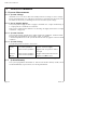
9.3
Tamper Faults
Tamper faults can be caused by
A tamper switch open, or broken cable or connection.
Two biscuits reporting at the same address
A faulty biscuit
Cable faults
RF Interference.
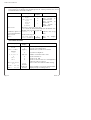
ALWAYS ascertain the complete picture of devices in tamper condition, and think
about possible possible causes, before investigating individual faults.
Remember iDA: information - Deliberation - Action, in that order!
This will provide clues to trace the true source of the problem, which may not be at
the zone indicated - eg imagine that a tamper fault has been indicated on zone 2 of a
system wired as follows:
A
01
10
05
14
08
C
09
02
07
12
04
D
15
13
06
03
11
E
B
Page 24
Issue: 4a
1700 Alarm System Installation Instructions
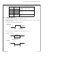
a) If zone 2 alone is in fault, the problem will be a tamper switch open, poor
connection, or faulty biscuit at zone 2.
b) If zones 2, 4, 7 and 12 all show a tamper fault, the problem is a break in the
cable between biscuits 2 and 9, or poor connection at 2 or 9.
c) if zone 13 (say) is also showing a tamper fault, either one of the biscuit
numbers is duplicated, or one of these biscuits is faulty.
Similar conclusions can be drawn for other combinations of indications.
Other tamper problems may occur as follows:
a) A tamper fault generated when a detector is triggered is invariably caused by the
detector being wired incorrectly (tamper should be in yellow connection, switch
connection between blue and white.)
b) A tamper fault generated when a different detector is triggered is almost
certainly due to a wiring problem, with an excessive resistance between the panel and
the detector being tripped. Check the resistance readings at section 8 (step 4),
checking the results against those expected for the cable distance used.
c) Random tamper faults can be induced by a biscuit with the WHITE wire connected
to YELLOW instead of BLUE.
d) Tamper problems when the loudspeaker is sounding are likely to be caused by
the connections being run with, or very close to, the iD network. Adjust wiring as
necessary.
e) The entire network giving random tamper problems is likely to be caused by
interference induced into the cabling from mains, telephones, etc. Examine the
routing and adjust, or use screened cable.
9.4
Checking the iD Line for Shorts
A short on the iD line will result in the iD fuse on the End Station pcb failing. The line
may be checked by removing the L+ and L- (Yellow and Blue) connections, and
measuring the resistance. See table at 8.1 for correct resistance values.
Any reading LESS THAN 2KW, or substantially less than the table suggests, would
indicate a short of some kind, or faulty biscuit. When the fault is cleared, replace the
fuse with one of the correct value (160 mA), replace the wiring in the terminals, and
re-test.
9.5
Use of Test Meters
iD biscuits do NOT need to be disconnected during normal voltage or resistance
measurements, provided that no voltages in excess of 12v are applied by the meter.
Do NOT therefore use a 'megger' or similar instrument for testing.
Additional checks are possible using the 'iD Test Meter' marketed by ACT Meters Ltd
iD FAULT FINDING:
Follow iDA: information - Deliberation - Action, in that order!
Check that all specifications summarised after 7.4.9 have been followed.
January 2000
Page 25
Castle Care-Tech Ltd.
10 Programming the System
The system requires certain information to be programmed into the memory in order
for it to function. The engineer should familiarise himself with the options available
and how they are selected. A form is provided to enable the system parameters to be
decided upon before commencing to program the system.
Programming is performed via the keypad.
10.1 Programming Options
To programme the system, enter 'Programming mode' as follows:
Action
Text Display
7-Segment Display
Enter 1111 (default Engineer Engineer Mode
Enter command
Code), followed by #
P
Flashing
The range of options available to be programmed is as follows:
Set Zone Parameters and Attributes
Set Timers
Set Sounder Options
Set Alarm Response in 'Part Guard'
Assign Outputs
Set Site Options
Select Keypads
Engineer Tests
View or Clear Logs
Each of the options is selected direct from the Programming prompt by a 2-digit
code, as shown on the succeeding pages.
Return to 'day' mode is by use of the 'NO' (*) key.
Remember:
The # key steps through and confirms options.
The * key aborts the current option
The '0' (zero) key changes the option.
Page 26
Issue: 4a
1700 Alarm System Installation Instructions
10.1.1 Zone Programming
Command 1x#
The 1700 Control Panel is despatched from factory with all circuits 'isolated' and
awaiting programming, which is performed as follows:
Action
Select zone number, preceded by 1
(eg 13# for zone 3, 115# for zone 15,
etc.)
Use numeric keys to select zone type
required, from table below, eg 3
Press #
Text Display
Zone 03
Isolated
7-segment Display
07
(ie zone type)
Zone 03
3
Intruder
Zone 03
0 (Flashing)
Non-omit Off
(ie zone attribute)
Zone 03
Use 0 to select/ deselect attribute
0 (steady)
Non-omit On
Zone 03
Press # to select next attribute
1 (steady)
Chime
Off
etc.
Zone 03
#
3 (steady)
Omit in B Off
etc.
Zone 03
#
4 (steady)
Active in C Off
etc.
Zone 03
#
3
iD assignment 03
Zone 03
Use number keys to enter number of
28
iD assignment 28
iD biscuit to be used -eg 28
Care should be taken to avoid having a biscuit number assigned to more than one
zone - even if one is programmed as 'isolated'
Zone 03
__
Press #
Zone 3
The system is ready to accept the
NOT APPLICABLE
entry
of
an
alternative
zone
SEE 7.1.2
description.
Engineer mode
P (flashing)
Press * to accept
Enter command
Table 1: Zone Type and Attribute codes.
ZONE TYPES
ZONE ATTRIBUTES
0
PA **
0
Non-omit
1
Silent PA **
1
Chime
2
24 Hr Tamper
2
Soak
3
Intruder
3
Part 'B' omit
4
Entry-Exit (final door)
4
Active in Part 'C'
5
Walk Through ***
(Entry -exit in 'Part set')
6
Fire **
7
Isolated
January 2000
** - These zone types MUST have the 'Live in C'
attribute as ON (if part C is in use).
*** - A Walk Through zone should use biscuit
numbered immediately higher than that for the
Final Exit-Entry zone to which it relates.
Page 27
Castle Care-Tech Ltd.
10.1.1.1 Programming English Text Zone Descriptions
(Liquid Crystal Display Systems only)
At the appropriate stage of zone programming, as described at 10.1.1, up to 16 text
characters may be entered one at a time using the 2-digit codes shown in the
following table:
A
B
C
D
E
F
G
H
I
J
K
L
M
33
34
35
36
37
38
39
40
41
42
43
44
45
N
O
P
Q
R
S
T
U
V
W
X
Y
Z
46
47
48
49
50
51
52
53
54
55
56
57
58
a
b
c
d
e
f
g
h
i
j
k
l
m
65
66
67
68
69
70
71
72
73
74
75
76
77
After entering each code, press # revealing the character programmed.
n
o
p
q
r
s
t
u
v
w
x
y
z
78
79
80
81
82
83
84
85
86
87
88
89
90
0
1
2
3
4
5
6
7
8
9
16
17
18
19
20
21
22
23
24
25
Space
,
.
/
"
&
(
)
*
00
12
13
14
15
02
06
08
09
10
the cursor will move to the next position,
Press '*' key to terminate text string, and return to the programming prompt. This text
will be shown on the Display in place of the Zone number.
10.1.1.2 Clean Zone Text
Command 83#
All text strings are initially blank, until programmed. To initialise these as 'Zone 1,' etc.
perform 'Clean Zone Text' by entering command 83#.
This may also be used to clear all existing programmed text if a system is being
reprogrammed, etc.
Page 28
Issue: 4a
1700 Alarm System Installation Instructions
10.1.2 Set Exit Mode and Time
Command 21#
The exit mode to be used for the system, and the required exit time are programmed
as follows:
Action
Text Display
7-Segment
Display
Enter 21#
Exit mode
Timed
t
Change mode as required
with 0 key
Exit mode
Terminated
Press
#
to
register
selection in memory
flashing
Timed exit mode
selected
steady
Terminated
exit
mode selected
Exit time
030 secs
(Not available if
'terminated' selected)
30
(alternately)
Exit time set at 30
seconds
Use number keys to
select time required (3
digits)
Exit time
020 secs
20
(alternately)
Press
#
to
register
selection in memory
Engineer mode
Enter command
P
flashing
t
then ' .'
Exit time adjusted
to 20 seconds
When using 'Terminated' option, exit time is automatically endless, and is terminated
by closure of the Final exit zone. When 'Part' setting, the system will default to
'timed' exit. To program the exit time required for 'Part' setting, first select 'Timed'
mode, and the time required, then enter the option again and change to 'Terminated.'
To use a 'Push to Set' facility, set exit mode as 'TIMED' with a setting ending in '9' (eg
19, 29 etc secs). When 'FULL' setting, exit time will be ENDLESS, until terminated by
making the 'Push to Set' input live. When 'PART' setting, the system will apply the
programmed time in the normal way.
10.1.3 Set Entry Time
Command 22#
The required Entry Time is programmed as follows:
Action
Liquid Crystal
7-Segment
Display
Display
Enter 22#
Entry time
030 secs
30
(alternately)
Currently set at 30
seconds
then ' .'
Use number keys to
select time required (3
digits)
Entry time
045 secs
Press # to register Engineer mode
Enter command
selection in memory
January 2000
45
(alternately)
Entry
adjusted
seconds
to
time
45
P
flashing
Page 29
Castle Care-Tech Ltd.
10.1.4 Bell Duration and Bell Delay
Commands 23# and 24#
The Bell Duration and Delay times are programmed as follows:
Action
Text Display
7-Segment
Display
For Bell DURATION
Enter 23#
Bell time
015 mins
15
(alternately
Current setting 15
minutes
then ' .'
OR: For Bell DELAY
Enter 24#
Bell delay
000 mins
0
No delay set
then ' .'
To amend setting:
Use number keys to
select time required (up
to 3 digits) ... eg
Bell delay
012 mins
Press
#
to
register Engineer mode
Enter command
selection in memory
12
(alternately)
Bell duration time
adjusted to 12
minutes
P
flashing
Regardless of the 'BELL DELAY' setting, the bell output will trigger INSTANTLY in the
following circumstances:
An alarm created within 90 seconds of the system being set.
An alarm following the commencement of Entry time (either expiry of
entry time or deviation from entry route)
An alarm generated whilst 'Full' alarm response is not valid.
10.1.5 Re-Arm Count
Command 25#
This option selects the number of times that the system will automatically re-arm
before shutting down to await resetting.
NOTE: Fire and PA zones remain live after the remainder of the system is 'locked out.'
Action
Text Display
7-Segment
Display
Enter 25#
Re-arm count
000
0
then ' .'
Use number keys to select
number required (up to 3
digits)
Re-arm count
003
3
Press # to register selection Engineer mode
Enter command
in memory
No re-arm set
System will re-arm
3 times before
locking out
P
flashing
10.1.6 'Just in Case' Timer
This timer is fixed at 60 seconds.
Page 30
Issue: 4a
1700 Alarm System Installation Instructions
10.1.7
Sounder Options
Commands 31# to 34#
The options available are:
Strobe flash (approx. 5 secs) to confirm exit
Sounders continue after bell cut off
Silent Keypad PA alarm
Strobe cease with bell time
These are selected as follows:
Action
Text Display
For 'Strobe Output Confirms
Set' Enter 31#
7-Segment
Display
Sounder Options
Strb cnf ext On
1
flashing
Option is
selected
For 'Sounder Continues After Sounder Options
Sdr aft bell
Off
Bell Time' enter 32#
1
steady
Option is NOT
selected
For 'Silent Keypad PA Alarm' Sounder Options
Sil 2-key PA Off
enter 33#
1
steady
Option is NOT
selected
Sounder Options
Str = bell Off
1
steady
Option is NOT
selected
Sounder Options
Str = bell
On
1
flashing
Option is now
selected
Engineer mode
Enter command
P
flashing
For 'Strobe Cease with Bell
Time,'' enter 34#
TO CHANGE SETTING:
Use 0 key
response ... eg
to
change
Press # to register selection
in memory
10.1.8 Alarm Response in 'Part Guard'
Command 40#
Programme the alarm response required when the system is 'PART SET' ('B' or 'C') as
follows:
Action
Text Display
7-Segment
Display
Response in Part
Local
2
Option 2 is
currently set
Use number keys to select Response in Part
Full
number required (1 to 3 see below)... eg
Press # to register selection Engineer mode
Enter command
in memory
1
Option 1 now
set
Enter 40#
OPTION:
January 2000
1
Full
2
Local
3
Sounders only
P
flashing
Full Alarm
Bell, Strobe and Sounders
Internal Sounders Only
Page 31
Castle Care-Tech Ltd.
10.1.9
Assign Outputs
Commands 50# and 51#
The programmable outputs may be programmed as follows:
Action
Text Display
7-Segment
Display
Assign output 1
PIR latch
1
Option 1 is
currently set
Use number keys to select Assign output 1
Viper reset
number required (see below)... eg
Engineer
mode
Press # to register selection in
Enter command
memory
2
Option 2 now
set
Enter 50# (Output 1) or
51# (Output 2)
OPTION:
1
PIR latch
2
Viper reset
3
Armed
P
flashing
May be inverted - see 7.1.15
4
Alarm
5
Pulse on chime
6
Medical
7
Lighting
Refer to Section 11.4 for specifications of these output options.
10.1.10 System Reset
Command 61#
The system can be programmed for either Engineer or User Reset, as follows:
Action
Enter 61#
Text Display
7-Segment
Display
Site Options
Eng reset
Off
1
steady
Use 0 key to change Site Options
Eng reset
On
option selected.
Engineer
mode
Press # to register
Enter command
selection in memory
1
flashing
Set for
reset
USER
Now
set
for
Engineer reset
P
flashing
If the Engineer Reset option is selected, following a FULL alarm the keypad will
display 'Engineer Reset' (or a flashing 'd') and the system will be locked out, awaiting
reset by an authority higher than the user.
Reset may be performed by entering the ENGINEER code, and returning to 'day' mode.
Alternatively, if a 'user' code is entered, the display will show (or scroll through) a
four digit number. This number may be referenced to a special lookup programme to
generate a special code which may be quoted to the user by an Alarm Monitoring
Centre, or Installing Company, to enable reset to be performed by the user.
Page 32
Issue: 4a
1700 Alarm System Installation Instructions
10.1.11 Misoperation (Abort) Signalling
Command 62#
The system provides a measure of protection for the operator who makes a mistake
in the Entry procedure. This may be adjusted as follows:
Action
Text Display
Site Options
Abort
Off
7-Segment Display
Enter 62#
1
steady
Option
NOT set
is
Use 0 key to change option
selected as required
Site Options
Abort
On
1
flashing
Option
now set
is
Press
#
to
register Engineer mode
Enter command
selection in memory
P
flashing
If the abort option is NOT selected, normal set and unset monitoring will be
available. When the system is unset following the generation of a 'Full' alarm
(including communicator 'Intruder' output) the communicator channel will restore,
and also the 'Set' channel will restore, enabling the Central Station response to be
aborted if received within an agreed time.
If the abort option IS selected, no set / unset monitoring will be available. Instead,
dedicated 'abort' signalling will be valid. When the system is unset following the
generation of a 'Full' alarm (including communicator 'Intruder' output) the
communicator channel will restore, and a dedicated 'abort' signal will be generated
(code 4), enabling the Central Station response to be aborted if received within an
agreed time.
10.1.12 Programming Access Codes
Command 63# and 64#
The Engineer access code on all new systems is 1111, and the Manager code is 2222
These may be changed as follows:
Action
Text Display
Site Options
Engnr code - - - Site Options
Use number keys to
Engnr code 2580
enter required code ..eg
Engineer mode
then
Enter command
Enter 63#
Site Options
Mangr code - - - Site Options
Use number keys to
Mangr code 7890
enter required code ..eg
Engineer mode
then
Enter command
Enter 64#
7-Segment Display
' .'
display follows keys New code
accepted
P
flashing
' .'
display follows keys New code
accepted
P
flashing
Note that the Manager code may also be programmed through the Manager menu.
User codes may only be programmed through the Manager menu.
January 2000
Page 33
Castle Care-Tech Ltd.
10.1.13 Select Keypads
Command 65#
Action
Text Display
7-Segment
Display
Enter 65#
Site Options
Rem keypads 1
1
1 keypad
enabled
Use number key (0 to 3) to
select number of keypads
Site Options
Rem keypads 2
2
Now 2 keypads
enabled
Press # to register selection Engineer mode
Enter command
in memory
only
P
flashing
NOTE: If 0 keypads are selected, the system will accept code entries, etc. from any
keypads which may be fitted, but will NOT generate a tamper alarm if the cover is
removed from a keypad. Individual keypads should first be coded as described at 7.1
Enabling a keypad which is not fitted will result in a system tamper alarm being
generated (indicating 'Sys tamper', or 'FF 1').
1
10.1.14 Inversion of Outputs
Command 67#
Certain output configurations shown at 6.1.6 and 11.4 may be inverted to suit
alternative requirements for some installations:
Action
Text Display
7-Segment
Display
Enter 67#
Use 0 key to change
option selected
Site Options
Invert PIR
Off
steady
Site Options
Invert PIR
On
flashing
L
L
Normal PIR Latch
output selected
Inverted output now
set
Site Options
Press # to move to next
Invert bell Off
option
steady
Site Options
Use 0 key to change
Invert bell
On
option selected
flashing
Site Options
Press # to move to next
Inv digicom Off
option
steady
Normal
digicom
outputs (+5v applied)
selected
Site Options
Use 0 key to change
Inv digicom
On
option selected
c
flashing
Inverted outputs (+5v
removed) now set
Press # to register
selection in memory
Page 34
Engineer mode
Enter command
b
b
c
Normal bell output
(-ive applied) selected
Inverted output (-ive
removed, for SCB use)
now set
P
flashing
Issue: 4a
1700 Alarm System Installation Instructions
10.1.15 Keypad Alerts
Command 68#
This function enables the 'Simple Set' options to be used, and an additional range of
warning signals to be triggered from the Keypad. These are:
Just in Case
Code 1 *
Triggers
delayed
(Keypad) alarm
Fire
Code 7 *
Triggers
alarm
normal
PA Reset with normal
code
FIRE Reset with normal
code
These are enabled by the Engineer as follows:
Action
Text Display
7-Segment
Display
Enter 68#
Site Options
Alerts Off
1
steady
Use 0 key to enable
option
Site Options
Alerts On
1
flashing
Press # to register Engineer mode
Enter command
selection in memory
Option
enabled
not
Option now
enabled
P
flashing
This function must be selected to permit the Part On 'C' setting to be used.
10.1.16 Display version
Action
Text Display
Enter 69#
then
January 2000
Command 69#
7-Segment
Display
Version no.
2.6
2.6
(alternately)
Engineer mode
Enter command
P
flashing
Software version
number is 2.6
Page 35
Castle Care-Tech Ltd.
10.1.17 View System Logs
Command 81#
The system logs are displayed in chronological order, starting with the most recent.
The information is accessed as follows
Action
Enter 81#
Text Display
7-Segment
Display
Display indicates type of event which follows:
Type
A
Entry
records
Activation
Activation event
Type
a
Entry
records
Alarm
alarm event
Type
t
Entry
records
Trouble
trouble event
Press # or 0
an
an
a
Advances to next part of log entry
If '0' is used, the information displayed will include time
and date, use of # will by-pass this.
Press * / #
Continue to press # or
'.'
Indicates end of log
0 to read information
entry.
Press # (or 0)
Press *
Scrolls to next log entry
Engineer mode
P
Enter command
flashing
Exits
mode
log
display
Activation records:
Text Display
7-Segment
Display
Set
S
Records system being Set
Unset
U
Records system being Unset
User number
[figure]:
0
[figure]
1,2,3 or 4
1,2,3 or 4
9
9
System set in Part 'C'
Full
F
System set as Full
Part
P
System set as Part. Part set 'C' distinguished
from 'B' by code 9, as above.
Omitted zones
1 2
o1o2
(in turn)
Time :
Date :
Page 36
03:15
07/11
0
03 15 07 11
(in turn)
Identifies how system was activated:
Keyswitch or Simple Set
Number of customer code used
Zones 1 and 2 were omitted whilst setting
Event recorded at 3.15 am on 7th November
(Displayed only if scrolling with '0')
Issue: 4a
1700 Alarm System Installation Instructions
Alarm or Trouble Events
An Alarm event records information relevant to an alarm condition, a Trouble event
records information relevant to a fault condition whilst the system is unset.
Text Display
First to Alarm
Zone xx
First to Alarm
Sys tamper
First to Alarm
Mains fail
First to Alarm
Lo volts
First to Alarm
Batt fault
First to Alarm
Line fault
First to Alarm
System Restart
First to Alarm
2-key PA
Time : 23:10
Date : 21/04
7-Segment
Display
xx
F1
Records an alarm triggered by the zone numbered.
F2
Records an alarm triggered by a System (SAB, box,
Keyswitch or Keypad) tamper fault
Records a failure of the Mains supply
F3
Records a system voltage fault
F4
Records a battery fault
F5
Records a Telecom line fault
F6
Records the system microprocessor restarting
F7
Records an alarm generated from the keypad
23 10 21 04
(in turn)
Event recorded at 11.10 pm on 21st April
(Displayed only if scrolling with '0')
10.1.18 Print Logs
Command 82#
By using the command 82#, the logs will be output to a printer connected to the
system. See 6.1.8. This function is also available from the Manager menu.
The printer should NOT be left connected whilst it is not in use.
Alternatively the 'NVM Programmer' may be used to transfer the logs to a PC for
printing.
10.1.19 Clear Logs
Command 80#
This function should be used ONLY when you are certain that all information is
finished with, or when installing a new system, or new NVM chip.
Action
Enter 80#
then
Text Display
7-Segment
Display
Clearing
logs
'.'
flashing
Engineer
mode
Enter
command
P
flashing
Note this will remain
for a few seconds.
10.1.20 Returning to User Mode
Press * key when the Programming prompt is showing, to return to day mode
January 2000
Page 37
Castle Care-Tech Ltd.
10.2 Engineer Tests
The following tests are available to the Engineer whilst setting up the system:
10.2.1 Output Tests
Action
Enter 71#
Cancel test with #
Commands 71#, 72#, 73#, 75# and 78#
Text Display
7-Segment
Display
Engineer tests
Bell test
1
(flashing)
Engineer mode
Enter command
P
flashing
Bell output is
live
Output
cancelled
is
Other output tests function in the same way, using the following codes:
Strobe test
72#
Sounder test
73#
Communicator test
75#
(tests ALL communicator outputs)
Slow Scan mode
78#
(provides means of testing iD scan voltages refer 9.1)
10.2.2 Input tests
Action
Enter 76#
Command 76#
Text Display
7-Segment
Display
Engineer tests
I/p test Off
1
(steady)
Apply 0v to any of the Engineer tests
I/p test On
inputs - Full or Part
keyswitch, or 'PTS'
1
(flashing)
Input is inactive
Input is active
A brief tone will be
heard on the
sounder as the input
is operated.
Remove signal, and
repeat as required for
other inputs
Cancel test with #
Page 38
Engineer mode
Enter command
P
flashing
Output is cancelled
Issue: 4a
1700 Alarm System Installation Instructions
10.2.3 Walk test
Command 77#
Action
Text Display
7-Segment
Display
Enter 77#
Walk test
Zone 00
' .'
is
Walk test
Zone 02
2
Sounder chimes
as
zone
is
triggered.
As additional detectors
are activated
Walk test
Zone 04
4
Zone numbers
cycle
When a
activated
detector
Note that at any time, ALL zones which have been triggered will scroll on the
display, enabling the engineer to return to the panel and check, until
Cancel test with #
January 2000
Engineer mode
Enter command
P
flashing
Output is
cancelled
Page 39
Castle Care-Tech Ltd.
11
Notes for Guidance
11.1 System Measurements
11.1.1 System Voltage
Should be set to 13.8v DC to allow the standby batteries to charge at correct voltage.
Battery fault indication ('F 4') will show if the battery is disconnected, the battery fuse
has failed, or the battery is discharged to at least 2v below system voltage.
11.1.2 Power Supply Rating
The system power supply is able to supply a maximum of 1.2 amps continuously, or
1.5 amps peak for a maximum of 20 minutes.
If the 1700 is ordered in the small (size 'A') housing, the supply is derated to 0.8 amps
continuous, 1 amp peak.
11.1.3 System Current
The 1700 End Station typically draws 40mA in quiescent conditions, 120mA in alarm.
Keypads draw approximately 160 mA (LCD); 75mA. (7-segment)
A 16Ω loudspeaker fitted to the system will increase this by approx. 250mA in alarm
condition.
11.1.4 System Fusing
The following fuses are fitted to the system
Mains
250mA 20mm SLO blow
150mA if 1A Power Supply
Battery
1.5A 20mm Quickblow
1.25A if 1A Power Supply
12v
800mA 20mm Quickblow
Supplies ALL 12v positive outlets
from pcb
Hold Off
500mA 20mm Quickblow
Supplies NEGATIVE Hold off feed
iD Line
160mA 20mm Quickblow
Supplies +ive iD line feed
It is important that the fuse covers are correctly fitted before securing lid.
11.2
System Memory
The system programme information is held in non-volatile memory (NVM), and is
retained indefinitely at power-down, as is all log information.
Page 40
Issue: 4a
1700 Alarm System Installation Instructions
11.3
Volume Control
The speaker output signals are generated at the following volume levels:
Alarm
High
Maximum output level - not
Fire
High
adjustable
11.4
Entry
Medium
Exit
Medium
Tamper
Medium
Chime
Low
Adjustable, using control labelled
'VOL 1'
Further adjustable, using control
'VOL 0'
Output options
The output options are selected as shown at 10.1.9.
Output 1 is capable of driving a 65mA load, at both 0v and +12v. Output 2 will drive
65mA at 0v only.
The options provide the following signals:
1. PIR Latch
12v
0v
Also 12v
in Wa lk Test
Day
Set
Alarm or Day
NOTE: This output configuration may be inverted, see 10.1.14
2. Viper 12v Reset
2 secs
12v
0v
System Switch On
3. Armed
12v
0v
Set
January 2000
Unset
Page 41
Castle Care-Tech Ltd.
4. Alarm
12v
0v
Alarm
Unset
This output is triggered by an alarm which generates a code 3 digicom signal.
5. Pulse on Chime
12 Seconds
12v
0v
Chime
11.5 BABT Approval
The 1700 System is approved for connection to a public telecommunications system
via an approved communicating device. Quote Approval Number: NS/G/23/J/100003
Page 42
Issue: 4a
1700 Alarm System Installation Instructions
12 System Operation
Full details of the operation of the system are described in the "1700 Operating
Instructions" - available to suit either LCD or 7-segment display keypads.
12.1 Using the System - Summary
12.1.1 Setting the System
Enter the 4-digit 'User' code, followed by # (to Full set) or * (to Part B set).
Pressing * additionally within two seconds will set the system silently.
A# will switch to the CHIME mode - to alert the user if someone enters a door or
room designated as 'chime.' The display will show a musical note (or the 'Full stop')
whilst this mode is selected. The chime can be switched off by keying in A# again.
If the Simple set options are selected:
B# will set the system in the 'PART ON B' mode, (B#* sets silently)
C# will set the system in the PART ON 'C' mode (C#* sets silently)
D# will set the entire system.
There is NO indication on the display when the system is set.
12.1.2 Unsetting the System
The system is unset from FULL or PART set conditions by entering the full 4-digit
'User' code, followed by #.
It is NOT now possible to unset from Part set 'C' with 'C#' - the full code must be
used.
12.1.3 Silencing an Alarm
In the event of an alarm, this may be silenced by entering the 4-digit 'User' code,
followed by #. After checking the indication, the display may be cleared by pressing #.
12.2 Keypad Alerts
The 1700 system provides the following functions, if programmed to be available:
1* will start the 'Just in Case' timer which will run for 60 seconds. If not cancelled by
a valid user code, the alarm will sound. A brief pulsing tone will act as a reminder
that the timer is running.
If the user is nervous about answering the door to a stranger, this timer can first
be set to provide additional security.
7* will cause a FIRE ALARM to sound.
3 & 9, pressed simultaneously, will cause a PERSONAL ATTACK ALARM to sound.
These alarms are silenced by keying in the 'User' 4-digit code.
January 2000
Page 43
Castle Care-Tech Ltd.
13 Manager Functions
The following functions are available through the Manager menu:
Change User Codes
Change Manager Code
Walk Test
Bell Test
Display and Print Logs
Accessing Manager functions:
Action
Text Display
Enter 2222 (default Manager Manager Mode
Enter command
Code), followed by #
7-Segment Display
E
Flashing
To return to 'user' mode, press *
13.1 Changing Codes
The MANAGER and USER codes may be changed from the Manager menu. The same
procedure is used as described at 10.1.12, using the following codes:
1x#
15#
Change User code
Change Manager code
where x represents the number of the user code being changed, between 1 and 4.
To DELETE codes 2, 3 or 4, enter the code '0000.'
It is NOT possible to delete the Manager code, or User code 1.
Default codes are:
Manager: 1111
User 1: 1234
13.2 Testing the System
Test facilities duplicating the Engineer test facilities are available:
Walk Test:
Code 20#
Bell Test:
Code: 60# (test includes strobe)
13.3 Display System Logs
This function, duplicating the Engineer function, is accessed by code: 30#
The Manager menu does NOT permit the logs to be cleared.
13.4 Print System Logs
If the command 31# is used, the log will be output to a printer connected to the
system. (see 6.1.8).
A printer should NOT be left connected to the system when 'off line' or not in use.
Page 44
Issue: 4a
1700 Alarm System Installation Instructions
14 System Specifications
Designed to form the heart of an intruder alarm system complying with BS.4737. Fully
compliant with requirements of ACPO policy and NACP14.
20 iD detection zone alarm control system, all zones fully programmable
Compatible with keypads (up to three) providing either English text, or 7-segment
displays
Four User codes, plus Manager and Engineer codes, with Keyswitch option
'Full' and two 'Part' settings, along with 'Chime' option.
Programmed parameters, and system logs, stored in Non-Volatile Memory
Integrated Engineer Test facilities
Power Supply:
1.5 amp (1.2A continuous) or 1 amps (0.8 amps continuous)
System voltage: 13.80v DC
Current drain:
End Station:
40mA standby, 120mA alarm.
Keypad:
LCD:160mA 7-Seg: 75mA
Fuses fitted:
Mains
250mA
Battery
1.5A
12v
800mA
Hold Off (-) 500mA
iD Line
160mA
20mm SLO blow 150mA for 1A PS
20mm Quickblow 1.25A for 1A PS
20mm Quickblow
20mm Quickblow
20mm Quickblow
Castle Care-Tech Ltd. reserves the right to adjust the specifications of this
system in the interests of product improvement.
January 2000
Page 45
Castle Care-Tech Ltd.
15 Accessories for the 1700
1000 Keypad - Liquid Crystal Display (Cat No. CT.1030 )
NOT suitable for use with End Station pcbs of Issue 1, fitted software issue 1.0
1000 Keypad - 7-Segment Display (Cat No. CT.1000 )
iD addressable 'biscuits: supplied in packs of 10, specify 1-10, 11-20 or 21-30
CT.2515 Plug-in Biscuits
CT.2516 Wired biscuits
CT.2517 iD contacts
iD Junction boxes - see 7.4.6
CT.2518 iD 'DP' junction box
8440 ('Mini-Com') Communicator (Cat. No. CT.1100)
NB other Digi-coms, and STUs are electrically compatible, but may not fit into the
smaller housing.
GP Loom for connection of communicator (Cat. No. CT.1105) Refer section 6.1.7
DCIF Interface (Cat No. CT.1107 )
Interface module for buffering Communicator outputs for use with externally
mounted communicating device, or for use with device requiring +12v trigger signals.
16W boxed loudspeaker (Cat No. CT.5700)
NVM Programmer
Permits the system NVM to be programmed from a PC and transferred to the Control
unit, also transfer of system logs from NVM to PC to permit analysis and printing.
Page 46
Issue: 4a
1700 Alarm System Installation Instructions
16
Printed Circuit Boards
16.1
The 1700 Keypad
Terminals
Keypad
numbering
switches
Address
3
2
1
NVM
The 1700 Control Printed Circuit Board
Battery
Fuse
o C
n
AC input
iD
Fuse
Hold Off
Fuse
12v
r o
Fuse
t
c
e
Pnrietr
Connector
n
mo c ' D
Keyswitch
TERMINALS
Keypad
iD
Inputs/Outputs
Connections
January 2000
Page 47
Castle Care-Tech Ltd.
APPENDIX A: SUMMARY OF PROGRAMMING COMMANDS:
Programme Zones
Exit mode and time
Entry time
Bell Time
Bell Delay
Re-Arm count
Just-in-Case Timer
Strobe confirm set
Sounder continue after bell time
Silent Keypad PA
Strobe cease with Bell time
Alarm response in Part Guard
Assign Output no. 1
Assign output no. 2
Engineer Reset
Abort (Misoperation)
Change Engineer code
Change Manager code
Change Customer codes
Set Date and Time
Select number of keypads
Output inversions
Enable keypad options
Display software version
Bell Test
Strobe Test
Sounder Test
Communicator Test
Input Test
Walk Test
Page 48
iD Slow Scan mode
1x#
21#
22#
23#
24#
25#
31#
32#
33#
34#
40#
50#
51#
61#
62#
63#
64#
65#
67#
68#
69#
71#
72#
73#
75#
76#
77#
78#
View logs
Print logs
Clear logs
81#
82#
80#
Clear zone text (LCD models)
83#
x = number of zone
Not programmable
Via Manager menu
Via Manager menu
also via Manager menu
Use with care!
Issue: 4a
1. System Electrical Characteristics at Commissioning
Condition:
System
Voltage
System
Current
Battery voltage
*
Battery Charge
current
AC Noise
iD voltage levels (see 6.1)
Reset:
Mid:
High:
Quiescent
Full Alarm
* Measured with mains disconnected from system
2. Zone Options (see 10.1.1)
Zone No. iD Device Zone Type *
NonChime
Soak
Part B
Active in Text Description
No.
Omit
omit
Part C
1
1
2
2
3
3
4
4
5
5
6
6
7
7
8
8
9
9
10
10
11
11
12
12
13
13
14
14
15
15
16
16
17
17
18
18
19
19
20
20
* - Zone types: 0= PA; 1= Silent PA; 2= 24Hr Tamper; 3= Intruder; 4= Final E/E; 5= Walk Through; 6= Fire; 7= isolated.
APPENDIX : System Parameters Record
INSTRUCT-16;
Iss: 3
February 1997
3. Timer Options (See 10.1.2 to 10.1.5)
Program
Function
21
Exit Mode
Selection
Timed or Terminated
Options:
Exit Time
Seconds
22
Entry Time
Seconds
23
Bell Duration
Minutes
24
Bell Delay
Minutes
25
Re-arm
Number
4. Miscellaneous Options (See 10.1.7 to 10.1.15)
Programme
Option
Selection
Options:
31
Strobe confirm exit
Yes or No
32
Sounder cont. after bell cut off
Yes or No
33
Silent Keypad PA Alarm
Yes or No
34
Strobe cease with Bell time
Yes or No
40
Alarm response in Part Guard
50
Programmed output 1
51
Programmed Output 2
1= PIR; 2= VR; 3= Armed; 4= Alarm;
5= Pulse on Chime
61
Engineer reset enabled
Yes or No
62
Abort enabled
Yes or No
65
Number of keypads enabled
67
68
1= Full, 2= Local, 3= Sounders
0-3
PIR Latch output inverted
Yes or No
Invert Bell Output
Yes or No
Invert Digicom Outputs
Yes or No
Keypad Alerts Enabled
Yes or No
APPENDIX : System Parameters Record
INSTRUCT-16;
Iss: 3
February 1997
Castle Care-Tech Ltd.
INSTRUCT-34