1
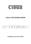
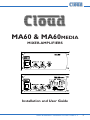
MA60 & MA60media MIXER-AMPLIFIERS I 0 I 0 Installation and User Guide MA60 & MA60media Installation and User Guide v1.2 1 WARNING: To reduce the risk of fire or electric shock, do not expose this appliance to rain or moisture. CAUTION: Use of controls or adjustments or performance of procedures other than those specified may result in hazardous radiation exposure. CAUTION RISK OF ELECTRIC SHOCK DO NOT OPEN WARNING: SHOCK HAZARD - DO NOT OPEN AVIS: RISQUE DE CHOC ÉLECTRIQUE - NE PAS OUVRIR The lightning flash with the arrowhead symbol within an equilateral triangle, is intended to alert you to the presence of uninsulated dangerous voltages within the product’s enclosure that may be of sufficient magnitude to constitute a risk of electric shock. The exclamation point within an equilateral triangle is intended to alert the user to the presence of important operating and maintenance (servicing) instructions in the literature accompanying the appliance. IMPORTANT SAFETY INSTRUCTIONS 1. 2. 3. 4. 5. 6. 7. Read these Instructions. Keep these Instructions. Heed all Warnings. Follow all instructions. Do not use this apparatus near water. Clean only with a dry cloth. Do not block any ventilation openings. Install in accordance with the manufacturer’s instructions. 8. Do not install near any heat sources such as radiators, heat registers, stoves, or other apparatus (including amplifiers) that produce heat. 2 MA60 & MA60media Installation and User Guide v1.2 9. Do not defeat the safety purpose of the polarized or grounding - type plug. A polarized plug has two blades with one wider than the other. A grounding type plug has two blades and a third grounding prong. The wide blade or the third prong are provided for your safety. When the provided plug does not fit into your outlet, consult an electrician for replacement of the obsolete outlet. 10. Protect the power cord from being walked on or pinched particularly at plugs, convenience receptacles, and the point where they exit from the apparatus. 11. Only use attachments/accessories specified by the manufacturer. 12. Unplug this apparatus during lightning storms or when unused for long periods of time. 13. Refer all servicing to qualified service personnel. Servicing is required when the apparatus has been damaged in any way, such as power-supply cord or plug is damaged, liquid has been spilled or objects have fallen into the apparatus, the apparatus has been exposed to rain or moisture, does not operate normally, or has been dropped. Do not expose the apparatus to dripping or splashing, and ensure that no objects filled with liquids, such as vases, are placed on the apparatus. L’appareil ne doit pas être exposé aux écoulements ou aux éclaboussures et aucun objet ne contenant de liquide, tel qu’un vase, ne doit être placé sur l’appareil. The mains plug is used as the disconnect device and it should remain readily accessible during intended use. In order to electrically isolate the apparatus from the mains, the mains plug should be completely removed from the mains outlet socket. La prise du secteur ne doit pas être obstruée ou doit être facilement accessible pendant son utilisation. Pour être complètement déconnecté de l’alimentation d’entrée, la prise doit être débranchée du secteur. This apparatus is of Class I construction and must only be connected to a mains outlet socket with a protective earthing connection. Terminals marked with the ( ) symbol may use Class 2 Wiring, but voltages at these terminals may be of sufficient magnitude to constitute a risk of electric shock. The external wiring connected to these terminals requires installation by an instructed person or the use of pre-made leads or cords. MA60 & MA60media Installation and User Guide v1.2 3 Contents Safety Information.........................................................6 Safety notes regarding installation........................................................ 6 Conformities.............................................................................................. 6 Safety Considerations and Information............................................... 7 CAUTION – High Voltages................................................................ 7 CAUTION - Mains Fuses................................................................... 7 CAUTION – Servicing........................................................................ 7 General Description.......................................................8 MA60 and MA60media main features.................................................. 8 Applicable Models..................................................................................... 9 What’s in the Box..................................................................................... 9 Block diagram.............................................................. 10 Front panel description.............................................. 11 Rear panel description................................................ 12 Installation................................................................... 14 Mechanical................................................................................................ 14 Rackmounting a single unit............................................................... 14 Rackmounting two units................................................................... 15 Ventilation................................................................................................. 16 Connections and adjustments............................................................. 16 Music inputs......................................................................................... 16 Mic input............................................................................................... 18 Outputs................................................................................................ 20 Music Mute Input................................................................................ 25 Ext Standby Input............................................................................... 26 MA60media digital media player............................... 27 Compatible media.................................................................................. 27 File types and rates supported............................................................ 27 Basic operation........................................................................................ 28 Normal Mode...................................................................................... 28 Repeat mode....................................................................................... 29 Random Mode..................................................................................... 29 4 MA60 & MA60media Installation and User Guide v1.2 Appendix...................................................................... 29 Installation of speaker EQ cards.......................................................... 29 Installation Instructions..................................................................... 30 PCB layout diagrams.............................................................................. 30 Table of internal jumpers and default settings.............................31 General Notes......................................................................................... 32 Multi-zone applications..................................................................... 32 EMC considerations........................................................................... 33 Earthing................................................................................................. 33 Technical specifications.......................................................................... 34 General specifications............................................................................ 35 MA60 & MA60media Installation and User Guide v1.2 5 Safety Information Safety notes regarding installation • Do not expose the unit to water or moisture. • Do not expose the unit to naked flames. • Do not block or restrict any air vent. • Do not operate the unit in ambient temperatures above 35 °C. • Do not touch any part or terminal carrying the hazardous live symbol ( ) while power is supplied to the unit. • Do not perform any internal adjustments unless you are qualified to do so and fully understand the hazards associated with mains operated equipment. • The unit has no user serviceable parts. Refer any servicing to qualified service personnel. • If the moulded plug is cut off the AC power lead for any reason, the discarded plug is a potential hazard and should be disposed of in a responsible manner. Conformities This product conforms to the following European EMC Standards: BS EN 55103-1:2009 BS EN 55103-2:2009 This product has been tested for use in commercial and light industrial environments. If the equipment is used in controlled EMC environments, the urban outdoors, heavy industrial environments or close to railways, transmitters, overhead power lines etc. the performance of the unit may be degraded. The product conforms to the following European electrical safety standard. BS EN 60065:2002 (+A2:2010) The MA60 and MA60media mixer-amplifiers have been developed and manufactured with high quality materials and components, which can be recycled and/or re-used. 6 MA60 & MA60media Installation and User Guide v1.2 Safety Considerations and Information The unit must be earthed. Ensure that the mains power supply provides an effective earth connection using a three-wire termination. When the mains switch is in the off (‘O’) position the live and neutral conductors of the mains transformer are disconnected. CAUTION – High Voltages Do not touch any part or terminal carrying the hazardous live symbol ( ) while power is supplied to the unit. Terminals to which the hazardous live symbol refers require installation by a qualified person. CAUTION - Mains Fuses The MA60 and MA60media mixer-amplifiers are fitted with a replaceable mains fuse. This is located on the rear panel below the AC mains input connector. Only replace the fuse with one of an identical type and rating. AC VOLTAGE FUSE TYPE FUSE RATING 230 V or 115 V 20 mm x 5 mm, T2A 2 amp Note that the failure of the mains fuse may indicate an internal fault. If a replacement fuse fails immediately the power is restored, no further attempt should be made to use the mixer-amplifier, and it should be returned to your Cloud service centre or other qualified person for repair. CAUTION – Servicing The unit contains no user serviceable parts. Refer servicing to qualified service personnel. Do not perform servicing unless you are qualified to do so. Disconnect the power cable from the unit before removing the top panel and do not make any internal adjustments with the unit switched on. MA60 & MA60media Installation and User Guide v1.2 7 General Description The Cloud MA60 and MA60media are compact and versatile mixer-amplifiers suitable for use in Licensed Premises, Retail, Leisure and many other venues. The units can deliver 60 W (mono) into 4 ohm loads; a transformer option is available for driving 100 V, 70 V or 50 V-line loudspeaker systems. The MA60media has an integral digital media player which replays audio files in various formats from SD cards or USB memory devices. In all other respects, the two models have identical facilities. There are inputs for four stereo line signals and a microphone input for paging/ announcement use. Front panel controls are provided for music source selection, music level and microphone levels; the MA60media has additional controls for the digital media player section. There are also various controls of the ‘preset’ type on the rear panel, and further unit configuration jumpers mounted internally on the main PCB. A remote level control or combined level control/music source selector can be wired to the unit for installations that require remote control. MA60 and MA60media main features • Four-input mixer-amplifier with integral 60 W mono power amplifier • Built-in digital music player supports MP3 and WMA files from USB memory sticks or SD (or MMC) cards at a wide range of standard data rates/sample frequencies (Model MA60media only) • Gain trims on all inputs • Electronically-balanced mic input • MIC input may be configured as telephone system interface to allow paging from phone extensions • Front panel controls for music source/level and mic level • 3.5 mm jack input (LINE 2) for MP3 player, laptop, etc. • Overall HF & LF EQ adjustment • Short-to-ground paging with VOX or access-triggered mic-over-music priority • Selectable LINE 4 priority over other music inputs • Music Mute control input (NO or NC) for interface to emergency system • Compatible with standard Cloud remote control panels – RL1 (music level) and RSL4 (music level and source selection) • Electronically-balanced pre-amp output (e.g., for connection to additional amplifiers) • Transformer-isolated auxiliary output with independent mic and music level control - for use with telephone MOH systems 8 MA60 & MA60media Installation and User Guide v1.2 • Auxiliary output source selection (by internal jumper) – source may be fixed or following main output • Remote Standby control input • 2U half-width (9.5”) rack mounting unit Available Options: • RL-1 (UK) and RL-1A (USA) remote control panels for music volume • RSL-4 (UK) and RSL-4A (USA) remote control panels for music source selection and volume • 100/70/50 V-line output transformer Model CXL-50T * • A range of EQ cards, to match various popular loudspeakers* • RE-L 19” rack mounting kit for one unit • RE-S 19” rack mounting kit for two units * these items are internally-fitted Applicable Models This manual describes the installation and operation of the following models: • Cloud MA60 4-input 60 W mono mixer-amplifier • Cloud MA60media4-input 60 W mono mixer-amplifier with integrated digital media player All models are 2U, half-rack width units. Apart from the inclusion of the digital media player in the MA60media, the two models are identical for the practical purposes of installation and operation. Unless specifically stated otherwise, the information in this manual may be taken to apply to either model. What’s in the Box Please check the shipping carton for damage before opening. If there is damage, please contact your Cloud agent and the shippers. The packing carton should contain the following items: • MA60/MA60media mixer-amplifier • AC mains lead with IEC connector • Set of mating plug-in screw-terminal connectors • Set of four rubber feet • This manual MA60 & MA60media Installation and User Guide v1.2 9 Block diagram CONNECT INPUT TO 0V TO OPEN MIC CHANNEL PHANTOM POWER 15V ACCESS BYPASS ACCESS INPUT 0V ISOLATION TRANSFORMER MIC 1 MIC EQ BYPASS TEL INPUT TRANSFORMER 0V SPEAKER OUTPUT OPTIONAL LINE OUTPUT TRANSFORMER 100Hz 100V 70V 50V COM 8 OHMS MOH SOURCE 0V 0V 0V 600 OHMS MIN LOAD 4 OHMS AVO MOH OUTPUT 0V MUTE CONTACT TYPE MEDIA PLAYER MUSIC MUTE LINE 1 + VCA LINE 2 FORCE FRONT PANEL SOURCE SELECT REMOTE LEVEL CONNECTOR 3 2 1 LINE 3 0V LINE 4 LINE 4 PRIORITY 3s RELEASE TIME 6s 12s-NO JUMPER EQ CARD BYPASS MIC PRIORITY RSL-4/RL-1 OPTIONAL REMOTE SOURCE AND LEVEL ON/OFF 10 MA60 & MA60media Installation and User Guide v1.2 EQ DCP EQ SOCKET 65Hz 0V 0V POWER AMPLIFIER HIGH PASS FILTER +VE - VE 0V 0V PRE-OUT FRONT PANEL MUSIC SOURCE AND LEVEL CONTROLS Front panel description 15 16 17 18 10 11 12 13 14 I 0 1 2 3 5 4 6 7 8 9 1. AC Power switch 2. Power ON LED 3. MICROPHONE LEVEL control – sets volume of mic input 4. MUSIC LEVEL control – adjusts music volume 5. PEAK LED – illuminates when internal signal clipping occurs 6. MUTE LED – illuminates when external Music Mute control is active 7. MUSIC SOURCE – rotary switch selecting music source (LINE 1* to LINE 4) The following front panel items are only fitted to the MA60media: 8. USB port – for connection of USB memory device containing audio files 9. SD Card slot – accepts SD or MMC memory cards containing audio files 10. PLAY/PAUSE button – starts or pauses playback of current track/file 11. STOP button – stops playback 12. PREVIOUS button – moves playback point to start of previous track or file 13. NEXT button – moves playback point to start of next track or file 14. MODE button – selects Random and Repeat Modes 15. PLAY LED – illuminates in PLAY mode 16. PAUSE LED – illuminates in PAUSE mode 17. RANDOM mode – illuminates when Random mode is selected 18. REPEAT mode – illuminates when Repeat mode is selected * On the MA60MEDIA, switch position 1 will select the digital media player if it has been enabled by the rear panel MEDIA/L1 button (see Rear Panel description). MA60 & MA60media Installation and User Guide v1.2 11 Rear panel description 1 20 3 5 2 6 7 15 16 14 4 13 11 10 12 9 8 17 18 19 1. LINE 1 to LINE 4 – stereo line inputs for music sources (phono sockets) 2. MP3/Laptop input – alternative LINE 2 input (3.5 mm stereo jack) 3. GAIN 1 to GAIN 4 – level trims for each line input 4.OUTPUT EQ – LF and HF EQ adjustment for music and mic signal (selectable to music-only by internal jumper) 5. MIC 1– balanced mic input 6. GAIN – mic input gain 7. ACCESS – external paging control input for MIC 1 8. LOW Z OUTPUT – speaker output for low-impedance circuits 9.LINE OUTPUT (under protective cover) - for connection to 100/70/50 V-line loudspeaker system, when optional internal transformer is fitted 10.MOH/UTILITY OUT – auxiliary output; can be used to provide Music On Hold to telephone system 11. MOH/UTILITY MIC LEVEL – sets level of microphone at MOH/UTILITY OUT 12. MOH/UTILITY MUSIC LEVEL – sets level of music at MOH/UTILITY OUT 13.PRE OUT – balanced line level output for connection of additional external amplifiers, etc. 14.MUSIC MUTE – Emergency control input for muting music source 12 MA60 & MA60media Installation and User Guide v1.2 15.REMOTE MUSIC CONTROL – for connection of RL-1 or RSL-4 remote control panels 16.REMOTE/LOCAL – enables remote music control connector and disables front panel controls (remote source select may be overridden by internal jumper) 17.EXT. STANDBY – for remote power-down by PIR sensor or other external control equipment 18. IEC mains input 19. Mains fuse The following rear panel item is only fitted to the MA60media: 20.MEDIA/L1 switch – selects Line 1 input to be external source or internal media player MA60 & MA60media Installation and User Guide v1.2 13 Installation Mechanical The MA60 and MA60media mixer-amplifiers may either be mounted in a standard 19” equipment rack or used free-standing. Each unit occupies 2U of vertical rack space and half a standard rack width. In order to install MA60/MA60media units in a 19” rack, rackmount kits (available from Cloud) must be fitted. Two types of rackmount kit are available: one for mounting a single unit, the other for mounting two MA60/ MA60media units side-by-side. See below for mounting instructions. If using the MA60/MA60media free-standing, the rubber feet (supplied with each unit) should be fitted. The unit should always be stood on a flat surface. Care should be exercised in selecting a location for a free-standing unit, which should allow ventilation but be clear of any liquid or similar hazard. Rackmounting a single unit A single MA60/MA60media may be rackmounted with the RE-L mounting kit. The RE-L kit consists of two rack brackets and eight M4 countersunk-head screws. To rack-mount a single MA60/MA60media, simply fit the two brackets as shown in the diagram below, using the screws provided. 14 MA60 & MA60media Installation and User Guide v1.2 Rackmounting two units Two MA60/MA60media units may be rackmounted side-by-side with the RE-S mounting kit. The RE-S kit consists of two rack ears, two connecting plates and sixteen M4 countersunk screws. To rack-mount a pair of MA60/MA60medias, proceed as follows: 1. Fit one of the rack ears to the left-hand side of one of the MA60s as shown in the diagram below, using four of the screws provided. 2. Repeat Step 1 for the right-hand side of the other MA60 unit. 3. Remove the two raised-head, hex-socket M4 screws at the right-hand side of the front panel of the first unit, and the corresponding two screws on the left-hand side of the front panel of the second unit. 4. Line the two units up next to each another, and fit one of the two flat connecting plates to the front panels, using four more of the screws provided. The raised-head screws are no longer required. 5. Repeat Step 4, fitting the remaining connector plate at the rear of the units. MA60 & MA60media Installation and User Guide v1.2 15 Ventilation MA60 and MA60media mixer-amplifiers are cooled by natural convection, via vents in the top and bottom panels. Always allow adequate space around the unit(s) to allow a free flow of air. In 19” rack installations we recommend leaving 1U of rack space above and below each unit. In free-standing installations, always fit the rubber feet supplied, and do not stand any other items on top of the unit. Connections and adjustments Music inputs The unit has four stereo line inputs, each of which is mixed internally to mono; these inputs are suitable for most music sources such as compact disc players, tape players, satellite receivers and the like. All inputs are unbalanced and use RCA phono sockets 1 . Line 2 has a second (parallel) input connector in the form of a 3.5 mm 3-pole jack socket 2 to allow convenient connection of a computer soundcard or MP3 player output. This is a stereo, unbalanced input on a single connector. Plugging into this socket will disconnect any source connected at Line 2’s phono connectors. Line 4 input can be configured to have priority over any other music source, see “Music Priority” on page 17. Sensitivity & Gain Control Each of the stereo line inputs has an input impedance of 47k ohms and a pre-set gain control on the rear panel below the respective input sockets 3 . The gain control has a range of 20 dB allowing the input sensitivity to be varied from -12 dBu to +8 dBu (0 dBu = 0.775 Vrms). The pre-set gain control should be adjusted so that all the input sources in use are at roughly the same volume and that the front panel level control has a useful range of control. Music Source Select This front panel four-position switch 7 is used to select the desired music signal. On the MA60media only, note that the first switch position will select either Line Input 1 or the internal digital media player, depending on the setting of the rear panel MEDIA/ L1 switch 20 . Remote control of source selection is possible with a remote control plate type RSL-4/RSL-4A, see “Remote Control of Music Source Select and Level” on page 17. 16 MA60 & MA60media Installation and User Guide v1.2 Music Level Control A front panel-mounted music level control 4 is provided. Remote control of music level is possible by connecting a remote control plate (either RSL-4/RSL-4A or RL-1/ RL-1A), see “Remote Control of Music Source Select and Level” on page 17below. If the music level is set too high, the front-panel PEAK LED 5 illuminates. Note that this LED also indicates excessive mic signal level. Remote Control of Music Source Select and Level The MA60 and MA60media mixer-amplifiers are compatible with standard Cloud remote control plates types RSL-4/RSL-4A (music source select and level) and RL-1/ RL-1A (level only). Either type of unit may be connected at the rear 3-pin 5 mm-pitch screw terminal connector 15 , using the wiring shown below. REMOTE SOURCE & LEVEL CONTROL WIRING REMOTE LEVEL CONTROL WIRING RL-1 1 REMOTE MUSIC CONNECTOR 1 2 3 1 2 SINGLE-CORE SCREENED CABLE MAY BE USED 3 2 3 REMOTE MUSIC CONNECTOR RSL-4 1 2 3 USE TWO-CORE SCREENED CABLE Use two-core (RSL-4/RSL-4A or RL-1/RL-1A) or single-core (RL-1/RL-1A only) screened cable to connect the remote level plate. The maximum recommended cable length is 100 m. Pressing the REMOTE/LOCAL button 16 above the rear panel connector activates the remote control plate and disables both the front panel level and source select controls. If an RL-1/RL-1A is being used, the internal jumper J9 should be moved from its default ‘SW’ setting to ‘FR’, to override the disabling of the front panel source select switch. See “PCB layout diagrams” on page 30 for further information regarding the internal jumpers. Music Priority One audio source can be given automatic priority over all other music inputs by connecting it to Line 4 input and moving internal jumpers J12A and J12B from the OFF position (factory default) to ON. This is a useful facility when a Juke Box, Digital MA60 & MA60media Installation and User Guide v1.2 17 Sound Store, emergency announcement system or similar source forms part of the audio system. When Music Priority mode is enabled, the unit will operate normally until a signal is detected at Line 4’s input. When this happens, the MA60/MA60media switches its music source automatically to Line 4 (assuming it is not already selected to Line 4). Once the signal at Line 4 stops (e.g., when the selected jukebox track has finished), the previously selected source will smoothly restore to its former level. The time taken for the restoration is set in the factory at 3 seconds, but it may be set at 6 or 12 seconds with internal jumper J11. (3s is suitable for announcements, but the longer times may be more appropriate when a jukebox or similar is the Line 4 source.) See “PCB layout diagrams” on page 30 for further information regarding the internal jumpers. Mic input The MA60 and MA60media are provided with a single microphone input, allowing the unit to be used for announcements. By default, the mic input has automatic priority over the music source. It is also compatible with paging microphones with zone selection by contact closure such as the Cloud PM range, including the PM1 singlezone microphone. See “Paging control” on page 19 for more details. The MA60’s microphone pre-amplifier is an electronically balanced, transformerless design configured for optimum low noise performance. The input impedance is greater than 2k ohms and is suitable for microphones in the 200 ohm to 600 ohm range. The connector is a 3-pin 3.5 mm-pitch screw terminal type on the rear panel 5 . Use the wiring shown below. Note that if using an unbalanced microphone, pins 1 and 2 should be connected together. MIC INPUT 1 2 MIC INPUT PIN 1: SCREEN (GROUND) PIN 2: COLD/ANTIPHASE (-) PIN 3: HOT/PHASE (+) 3 + 1 2 3 SCN SCN + BALANCED CONNECTION UNBALANCED CONNECTION 15 V phantom power is available at the mic input, and is activated by setting internal jumper J1 to the ON position. See “PCB layout diagrams” on page 30 for further 18 MA60 & MA60media Installation and User Guide v1.2 information regarding the internal jumpers. Care should be taken to ensure that phantom power is activated only when the microphone connected to the input requires it – i.e., a capacitor or electret type; other types of microphones (such as dynamic or ribbon) may be damaged if a DC voltage is applied to them. Mic gain adjustment The mic input has a preset gain control 6 adjacent to the input connector. The gain can be adjusted over a range of 40 dB, from 10 dB to 50 dB. A high overload margin is maintained at all gain settings. (Note - the gain range is modified if the telephone matching transformer is in circuit. See “Paging via a telephone system” on page 20 for more details.) Microphone level control A front panel level control 3 is provided for the mic input and this provides the user with a means of adjusting the volume of the microphone. The microphone signal is unaffected by the music level control 4 . The rear panel gain control 6 should be set at a level where microphone distortion does not occur even when the front panel level control is fully clockwise. If the mic level is set too high, the front-panel PEAK LED 5 will illuminate. Note that this LED also indicates excessive music level. Paging control The mic input is equipped with an external access control input; this is a 2-pin 5 mm-pitch screw terminal connector 7 adjacent to the mic input connector. The access input is primarily intended to provide compatibility with paging microphones and their associated switching arrangements. By default, mic priority over music is via AVO mode (Automatic VoiceOver) and the access port is disabled. In AVO mode, the presence of a signal at the mic input automatically activates the priority circuitry, and attenuates the current music source by 30 dB so that the announcement is audible. To use the access port, move internal jumper J5 from its default ‘ON’ setting to ‘OFF’. See “PCB layout diagrams” on page 30 for further information regarding the internal jumpers. Once enabled, the microphone input is muted as long as the pins of the access connector are open-circuit. When the pins are connected together, the mic input becomes active. In either AVO or SW mode, the music signal is faded back up after the announcement is complete. Unlike Line 4 priority, the fade-up time (‘release time’) is not adjustable. If the mic input is being used for a non-announcement purpose (such as karaoke), mic priority may be disabled by removing J14 altogether. In this setting, the mic input may be mixed as desired with the music source. (It is recommended that J14 is left attached to one pin of the header in case a different setting is needed in the future.) MA60 & MA60media Installation and User Guide v1.2 19 High pass filter The microphone signal path includes a fixed high-pass filter. This attenuates the mic signal below 100 Hz, which helps to reduce the effects of microphone handling noise. The filter may be taken out of circuit by moving internal jumper J7 from ON to OFF. See “PCB layout diagrams” on page 30 for further information regarding the internal jumpers. Paging via a telephone system The mic input on the MA60/MA60media may be reconfigured to accept an audio input directly from a compatible telephone system. This permits announcements to be made from some (or any) internal telephone extensions in a building. Not all telephone systems are suitable for this application, and the system documentation should be consulted in detail to ensure compatibility. Internal jumpers J2, J3 and J4 need to be moved for this application. See “PCB layout diagrams” on page 30 for further information regarding the internal jumpers. This inserts a transformer in series with the input connector to provide full electrical isolation from the telephone system. Note that the mic input sensitivity is decreased by 10 dB when the transformer is enabled, and this results in the mic gain control operating over the range 0 dB to 40 dB. The audio (or “paging”) output of the phone system should be connected to the MIC 1 input in the normal way. The telephone input is optimised for connection to a 600 ohm output; this should suit the majority of telephone systems. Note that the front panel MICROPHONE LEVEL control 3 is still operational. Outputs Lo-Z output The MA60/MA60media mixer-amplifiers are able to deliver their rated power of 60 W into a 4 ohm load. The output power will be reduced with higher load impedances. When using multiple low-impedance loudspeakers (normally 8 ohm) with a single amplifier, series and parallel wiring should be employed to produce a total load impedance of not less than 4 ohm. The low impedance output is available at the 2-pin 5 mm-pitch screw terminal connector on the rear panel 8 . Note that one of the output pins is connected internally to 0 V. 20 MA60 & MA60media Installation and User Guide v1.2 100/70/50 V-line systems An optional transformer kit (CXL-50T) is available for the MA60/MA60media, to permit the unit to directly drive 100 V, 70 V or 50 V-line loudspeaker systems. The transformer is rated at 50 W output, and is mounted internally. The outputs are available on a 4-pin 5 mm-pitch screw-terminal connector which occupies the hole in the rear panel normally covered by a blanking plate. 9 Fitting the CXL-50T transformer kit The transformer kit comprises the following items: • CXL-50T toroidal transformer, terminated in a PCB-mounted 4-pin connector • M6 countersunk-head fixing bolt • Safety cover • 2 x M3 hex pillars • 2 x M3 x 6 screws • Mating 4-pin connector • 2 x cable ties Proceed as follows: 1.Disconnect the MA60/MA60media from AC mains. 2.Take the top panel off by removing the eight M3 screws (six on the top panel itself; two through the front panel) securing it. 3.Turn the unit upside down, and remove the plastic blanking plug from the M6 hole in the base of the unit. (The hole is in the centre of the chassis, about 8 mm behind the front panel.) Insert the M6 fixing bolt supplied with the kit through the hole. 4.Fit the transformer with the fixing screw through its central core. The top of the transformer has a threaded M6 insert; tighten the screw from underneath using a hex key. MA60 & MA60media Installation and User Guide v1.2 21 100/70/50 V-LINE OUTPUT CONNECTOR PCB MAIN PCB Red/Brown/ Blue/Black CN15B CN15A White/Black MAINS TRANSFORMER CXL-50T OUTPUT TRANSFORMER MEDIA PLAYER PCB FRONT PANEL CONTROLS PCB FRONT PANEL 5.The primary winding of the transformer is terminated in a two-pin Molex-type connector. This should be plugged into the header marked CN15B on the main PCB. See “PCB layout diagrams” on page 30 for location. 6.On the rear panel, remove the plastic blanking plate covering the LINE OUTPUT connector hole. 7.Fit the 4-pin connector on the ends of the secondary winding leads from the transformer (the remaining four) into this hole, so that the threaded holes in the two PCB mounting brackets line up with the two holes alongside the connector. Use the male ends of the hex pillars (supplied) to secure the PCB and connector in place. 8.Use the two cable ties supplied to tidy up the transformer leads; ensure that they do not pass over the top of the main heat sink. 9.Replace the top cover, using the original screws. 10.Connect the speaker system to the line outputs using the mating connector. Note that only two of the pins will be used; one will always be pin 1 (0 V). 22 MA60 & MA60media Installation and User Guide v1.2 Connect to CN15B Red White Brown 1 100 V 2 70 V 3 50 V 4 COM Blue Black Black Pri. Sec. CXL-50T To 100/70/50 V-line speaker system Rear panel connector 11.After plugging the connector in, the safety cover should be fitted by securing it to the female ends of the hex pillars using the two M3 screws supplied. Important - Note that the low-impedance output should not be used once the line output transformer is fitted. Once the transformer is fitted, it is strongly recommended that the MA60/ MA60media’s 65 Hz high pass filter is set ON by moving internal jumper J13. This is to minimise distortion due to transformer saturation at low frequencies. See “PCB layout diagrams” on page 30 for further information regarding the internal jumpers. Output Equalisation Independent bass and treble EQ controls are provided for the main outputs. These are of the preset type and are located on the rear panel 4 . The treble control has a range of ±10 dB at 10 kHz and the bass control has a range of ±10 dB at 50 Hz. By default, this EQ adjustment affects only the music signal, but it may be enabled for the microphone input by moving internal jumper J10, in which case the rear panel controls will affect the both the music source and the microphone signal. See “PCB layout diagrams” on page 30 for further information regarding the internal jumpers. MOH/Utility output The MOH/Utility output (MOH = Music On Hold) is an auxiliary output which can be used as an extra output for various purposes. This is available both as a transformer-isolated line level output and a non-isolated low-power amplifier output (approx. 1 W). A common application for this output is to provide a continuous music-on-hold feed to a telephone system. It should be noted that a fixed LF filter reduces bass frequencies in this output to optimise it for use with telephone systems. The lowpower output is suitable for connection to systems that require a speaker level feed. MA60 & MA60media Installation and User Guide v1.2 23 The output connector is a 4-pin 3.5 mm-pitch screw terminal type on the rear panel 10 . Two of the pins (labelled ‘0 V’ and ‘8Ohm’) are the low-power, lo-Z output, with one pin connected internally to 0 V. The other two pins (labelled ‘600Ohm’) are the transfomer-isolated line level output, suitable for connection to a nominal 600 ohm load. The output level is nominally 0 dBu, and is transformer-coupled to provide full galvanic isolation from a telephone system. MOH/Utility Output 600 ohm 8 ohm 1 - 2 3 4 8 ohm OR 1 2 600 ohm 3 4 + To MOH input of telephone system Lo-Z loudspeaker Before using the MOH/Utility output with a telephone system, it is recommended that the system manual is consulted to check suitable audio levels and any other compatibility issues. MOH/Utility Output level and source The signal at the MOH/Utility output may be any required mix of the music signal and the microphone signal, and is set using the rear panel presets MIC LEVEL control 11 and MUSIC LEVEL 12 . The relevant signal level is zero with the preset control in its fully anticlockwise position. Note that the signal at this output is NOT altered by the front panel MUSIC LEVEL control or the rear panel MUSIC EQ preset adjustments. Note that the MIC LEVEL control should be turned fully down if the output is used for MOH with a telephone system, otherwise internal paging announcements will be heard by telephone callers. If the output is used as an auxiliary feed, it will generally need to follow the normal music source selection. This is the factory default configuration. If Music Priority is enabled (see “Music Priority” on page 17), the MOH/Utility output will switch to Line 4 along with the main output if the input becomes active. However, when in use with a telephone system as an MOH source, it is generally more desirable for the music source to remain constant, and not vary with the front panel MUSIC SOURCE control. For this purpose, the source for the MOH/Utility output can be fixed by moving internal jumper J6. Any of the four line inputs, or the alternative Line 2 MP3 input 2 , may be selected as the fixed MOH music source. See “PCB layout diagrams” on page 30 for further information regarding the internal jumpers. 24 MA60 & MA60media Installation and User Guide v1.2 Pre Out To permit the connection of additional amplifiers (or other equipment), a balanced output from the MA60/MA60media’s pre-amplifier section is available at a rear panel 3-pole, 3.81 mm-pitch screw terminal connector. MA60 Pre Out: pin 1 ground pin 2 cold pin 3 hot Balanced Input (e.g., XLR): pin 1 ground pin 2 hot pin 3 cold 3 1 2 3 - SCN + SCN MA60 Pre Out: pin 1 ground pin 2 cold pin 3 hot 1 2 1 2 SCN - + Unbalanced Input (e.g., phono) 3 + + SCN All the unit’s controls and settings on the front and rear panels (levels, source selection, priority settings, etc.) are effective at the Pre Out. However, note that neither the switchable 65 Hz high pass filter nor the fitting of an optional loudspeaker EQ card have any effect on this output. Music Mute Input In some installations (such as licensed premises or retail outlets within a shopping mall), there may be a local authority or fire service requirement to mute the music signals from a fire alarm control panel when an alarm condition arises. The MA60/ MA60media includes a facility to mute the music programme only (i.e., the mic input is still active), via the Music Mute input. This is a 2-pin 5 mm-pitch screw terminal MA60 & MA60media Installation and User Guide v1.2 25 connector on the rear panel. The input is usually connected to a pair of isolated relay contacts activated by the fire system. Note that the Music Mute function only mutes the MA60/MA60media’s main output; the MOH/Utility output remains active. When Music Mute is activated, the front panel MUTE LED 6 illuminates to confirm that the resulting silence is due to an external Music Mute command. Activation of the Music Mute is often via a relay mounted close to the MA60/ MA60media and any associated equipment, powered by the fire alarm control panel. Other arrangements may exist depending on the design of the fire control system and the fire alarm installation company should be consulted when making the connection. The MA60/MA60media will mute on either a contact closure at the Music Mute input (NO) or an open circuit (NC). Selection of NO or NC operation is made with internal jumper J15. NO is the factory default. See “PCB layout diagrams” on page 30 for further information regarding the internal jumpers. The diagram below shows the two connections. Ext Standby Input The MA60/MA60media may be remotely switched in and out of AC power standby mode by connecting the rear panel EXT STANDBY connector 17 to an external 5 V DC source. Providing the front panel power switch 1 remains on, 5 V DC applied across the terminals will cause the MA60/MA60media to to go into standby mode. The 5 V source used should be able to supply 40 mA. This is a useful feature as it permits the unit to be powered on and off from a system controller, for example. 26 MA60 & MA60media Installation and User Guide v1.2 MA60media digital media player NOTE: This section of the manual applies to the MA60media only The MA60media includes an integral digital audio player, which can play audio recorded as WMA or MP3 files from either USB memory devices or SD cards plugged into their respective sockets on the front panel 8 and 9 . A standard set of “transport” controls is provided on the front panel to play, stop, pause, etc., programme material. The stereo audio output of the media player is mixed to (L+R) mono and routed internally via the rear panel MEDIA/L1 switch 20 to Line Input 1. Thus to use the media player, the rear panel switch must be set to MEDIA (button ‘in’), and the front panel MUSIC SOURCE switch 7 set to Input 1/MEDIA. Compatible media USB: USB 2.0-compatible memory devices. SD:SD cards up to 4 GB capacity, or SDHC cards up to 32 GB. MMC cards of the same capacity are also compatible. Filing systems supported are FAT16 or FAT32. File types and rates supported The MA60media will replay audio files recorded in either WMA or MP3 formats, as follows: WMA: bitrates from 32 kpbs to 384 kbps MP3:MPEG 1/2/2.5, layer 2 or 3 decoding at bit rates from 32 kpbs to 384 kpbs, including VBR. Sample rates supported are: 8 kHz, 11.025 kHz, 12 kHz, 16 kHz, 22.05 kHz, 24 kHz, 32 kHz, 44.1 kHz and 48 kHz Both types of audio file may be present on the memory device; the MA60media will not differentiate between them in any way. The files may be in the root directory of the memory, or in folders, or folders within folders. When the memory device is plugged in, the media player will scan it and identify all compatible files in all folder locations, and make them available for playing. Only one memory device at a time (USB device or SD card) may be connected. Note that it is not possible to create a playlist from the MA60media’s front panel controls. Basic operation MA60 & MA60media Installation and User Guide v1.2 27 The front panel transport controls operate in a similar manner to the standard controls on, say, a CD player. Plugging a memory device into one of the front panel sockets will activate the player and after a short delay, the player will enter PLAY mode, confirmed by the illumination of the PLAY LED 15 . In Normal Mode (see below), the first track played is the one whose filename starts with the lowest numeric/alpha characters. The track playing may be momentarily paused by pressing the H button 10 ; the PLAY LED goes out and the PAUSE LED 16 illuminates to indicate this. Play is resumed from the point at which it was paused by a further press of the H button. The track may be stopped from either Play or Pause modes by pressing the A button 11 ; both LEDs go off. The next or previous track may be selected for immediate play by pressing the E or F button respectively. These buttons operate in any transport mode. (Unlike a CD player, the F button will cause the play point to jump to the start of the previous track, not that of the current one). Three operational modes are available, selected by the MODE button 14 (labelled with the symbol ). Successive presses of the MODE button step through the modes: The REPEAT and RANDOM LEDs 18 and Both LEDs off indicates Normal Mode. 17 illuminate to confirm these two modes. Normal Mode In Normal Mode, the media player plays through all the available audio files in order of filename, regardless of which folder they are in on the memory device. Numeric characters are given higher priority than alphabetic ones, so audio tracks whose filenames begin with numbers will be played first. This makes it very simple to pre-ordain track playing order; if the tracks are given filenames beginning “01”, “02”, etc., they will be always be played in that order in Normal Mode. 28 MA60 & MA60media Installation and User Guide v1.2 Repeat mode If Repeat Mode is enabled while a track is playing, the track will be repeated when it has finished. This repetition will continue until Repeat Mode is cancelled. Repeat Mode may also be selected from Stop Mode; the next track played when H is pressed will then repeat until Repeat Mode is cancelled. Note that Repeat Mode only applies to individual tracks; it is not possible to repeat a sequence of tracks. Random Mode In Random Mode, the next track to be played is selected at random from all the tracks available on the memory device. Note that this is not the same as the “Shuffle” mode found on portable MP3 players - a fresh random selection from all available tracks is made at the end of each track, and thus there is a possibility that the same track may be played twice in succession. Appendix Installation of speaker EQ cards The MA60 and MA60media are compatible with single channel loudspeaker equalisation modules. EQ modules are available from Cloud Electronics to suit the following Bose® and Amina loudspeakers: Bose: Panaray MA12 Panaray 402-II, 502B and 502BEX Panaray LT Series: Models 3302, 4402, 9402 and 9702. Amina:AIWX Series: Models AIW1X, AIW2X, AIW3X, AIW3X/S200, AIW4X, AIW5X LfiT Series: Models LFi2T, LFi4T Modules to suit other models are available – please enquire. MA60 & MA60media Installation and User Guide v1.2 29 Installation Instructions Refer to the PCB layout diagram (see “PCB layout diagrams” on page 30) for the location of the EQ module connector and its associated bypass jumper J8. To install an EQ module, proceed as follows: 1. 2. 3. 4. Switch off the power and isolate the unit from the mains. Remove the top panel. Move jumper J8 on the main PCB from ‘ON’ to ‘OFF’. Plug the loudspeaker equalisation module into its 12-pin connector CN16; note that the connector has two notches on one side which engage with lugs on the module’s mating connector to ensure correct orientation. 5. Replace the top panel. PCB layout diagrams The MA60 and MA60media have two PCBs which are fitted with jumpers, the Main PCB and the Input PCB. With the top cover removed from the unit, and the rear connector panel towards you, the Main PCB is fitted to the base at the rear of the chassis, while the Input PCB is mounted vertically on the Main PCB immediately behind the rear panel, and carries most of the connectors and controls. The diagrams below indicate the locations of the various jumpers, and also the EQ card socket. They are for guidance only and are not to scale. OFF ON J13 J2 (below ribbon cable) J3 J7 J4 CN15A OFF ON CN16 J14 AVO SW J1 NC NO OFF ON OFF ON CN15B ON OFF Lo-Z outputs OFF ON Loudspeaker EQ card socket J15 J8 Input PCB (vertically-mounted) J5 30 MA60 MAIN PCB VIEW FROM REAR NOT TO SCALE - Only primary components shown MA60 & MA60media Installation and User Guide v1.2 6S 3S ON OFF (REMOVE J11 FOR 12S) J11 J12A&B J9 L1 MP3 L2 L3 L4 SW SW FR OFF ON J10 J6 MA60 INPUT PCB VIEW FROM FRONT NOT TO SCALE - Only primary components shown Table of internal jumpers and default settings JUMPER ON PCB PURPOSE OPTIONS DEFAULT J1 Main Mic input phantom power ON/OFF OFF J2 Main J3 Main Mic input transformer isolation ON/OFF OFF J4 Main J5 Main Mic Access Bypass ON/OFF ON J6 Input MOH/Utility music source SW/L1/L2/L3/L4/MP3 SW J7 Main 100 Hz mic high-pass filter ON/OFF ON J8 Main EQ card bypass ON/OFF ON J9 Input Force front panel source selection FR/SW SW J10 Input Mic EQ bypass ON/OFF ON J11 Input L4 Priority Release Time 3 s/6 s/12 s (no jumper) 3s J12A Input J12B Input L4 Priority ON/OFF OFF J13 Main 65 Hz high-pass filter ON/OFF OFF J14 Main Mic priority AVO/SW/OFF AVO J15 Main Music Mute contact type NO/NC NO MA60 & MA60media Installation and User Guide v1.2 31 General Notes Multi-zone applications MP3 DOCK CD PLAYER TV TUNER 1 2 3 4 MAIN OUT LINE INPUTS MA60MEDIA JUKEBOX PRE OUT MIC INPUT 1 2 3 4 LINE INPUTS Where the sound system specification calls for separate control in several zones, MA60s and/or MA60medias can be used in multiples. These notes discuss the principle of connecting external input sources to several units in parallel. Note that the integral media player in any one MA60media will only play in the zone to which its output is connected. However, its Pre Out may be connected to the Line Inputs of additional units (Line 1 would be the logical choice), so that one media player can act as an external source for the other units. MAIN OUT MA60MEDIA 1 2 3 4 LINE INPUTS Signal sources can be connected to several inputs as required, but care must be taken to ensure the output stage of the signal source is capable of driving the resulting lower input impedance. The impedance of the line inputs (music inputs) is 47k ohm MA60MEDIA and it is reasonable to assume that most op-amp based signal sources are easily able to drive a 10k ohm load, allowing up to five MA60/MA60medias to be paralleled. ADDITIONAL MA60s The input impedance of the mic input is more than 2k ohm, making it suitable for microphones with a nominal impedance of 600 ohms or less. A single 600 ohm microphone could therefore typically be connected to four paralleled mic inputs. If this guideline figure cannot be adhered to, the use of suitable mic or line distribution amplifiers is recommended. MAIN OUT To avoid any problems associated with differences in mains supply earthing, we recommend that all MA60/MA60medias used in a multi-zone application should be co-located and connected to a common mains supply. Note that when using multiple MA60/MA60medias in a 19” rack, suitable ventilation arrangements must be made to ensure that lower units do not cause those above to overheat (see also “Ventilation” on page 16). 32 MA60 & MA60media Installation and User Guide v1.2 EMC considerations MA60 and MA60media mixer-amplifiers fully conform to the relevant electromagnetic compatibility (EMC) standards and are technically well behaved.You should experience no problems interfacing units to other items of equipment and under normal circumstances, no special precautions need to be taken. If the unit is to be used in close proximity to potential sources of HF disturbance such as high power communication transmitters, radar stations and the like, it is suggested that input signal leads be kept as short as possible. Always use balanced interconnections wherever possible. If the MA60/MA60media mixer-amplifier is mounted in a 19” rack, do not locate the unit in close proximity to a powerful amplifier of any kind, which may radiate a strong magnetic field from the power transformer. Earthing When several mains powered units are connected together via their signal cables, there is a risk of one or more earth loops which may cause an audible hum on the system even with the gain controls set to minimum. The 0 V rail of an MA60/MA60media mixer-amplifier is directly coupled to the chassis ground. No interconnection problems should be encountered, but if there is any hum or other extraneous noise when source equipment is connected, the situation can generally be remedied by observing the following guidelines: • Always connect sources using balanced connections wherever possible. Note that, for EMC reasons, the cable screen should be connected at both ends. • Use audio isolating transformers (readily available from trade suppliers) at the inputs if necessary. These will ensure that the amplifier is electrically isolated from the source equipment. • The signal source units should be located as close as possible to the amplifiers and the metal housing of the various units should not be electrically connected together through the equipment rack. If this is a problem, rack isolating kits are available from specialist hardware suppliers. If the problem persists, try to connect all interconnected units, including power amplifiers to a common power source to ensure a common ground is provided. MA60 & MA60media Installation and User Guide v1.2 33 Technical specifications Line inputs Low-Z output: +0 dB/-1 dB from 20 Hz – 20 kHz (65 Hz filter out) Frequency response 100/70/50 V-line outputs (with CXL-50T transformer fitted): +0 dB/-3 dB from 20 Hz – 20 kHz (65 Hz filter switched out) Low-Z output: <0.05% @ 1 kHz, 1 dB below full power (80 kHz bandwidth) Distortion High voltage output: <0.05% @ 1 kHz, 1 dB below full power (80 kHz bandwidth) Sensitivity 195 mV (-12 dBu) to 2.0 V (+8 dBu) Input Gain control 20 dB range Input impedance 47k ohms Headroom >20 dB Noise -93 dB, 22 Hz –22 kHz, at speaker output, relative to full power Microphone Inputs Frequency response Low-Z output: -3 dB @ 100 Hz (3rd. order filter); -1 dB @20 kHz High voltage output: -3 dB @ 100 Hz (3rd. order filter); -2 dB @20 kHz Distortion <0.05% @ 1 kHz, 1 dB below full power (80 kHz bandwidth) Gain range 40 dB range Input Impedance >2k ohms (balanced) Phantom Power 15 V, switchable per-input by jumpers Headroom >20 dB Noise -127 dB EIN 22 Hz-22 kHz (150 W) Outputs 60 watts @ 1 kHz & <0.07% THD+N Low impedance output 34 Output Power 50 watts @ 1 kHz & <0.07% THD+N 50/70/100V line outputs (optional transformer fitted) Equalisation HF: ±10 dB/5 kHz Protection Dynamic level signal limiter max gain reduction of 20 dB, thermal protection, IV limiting & short circuit protection, switch on delay LF: ±10 dB/100 Hz MA60 & MA60media Installation and User Guide v1.2 General specifications Power input 230 V, 115 V versions available Fuse rating 230/120 V - T2A H Fuse type 20 mm x 5 mm Cooling Convection cooled, vents top and bottom. Dimensions (mm) 213.0 wide x 88 high (2U) x 278 deep (+ connectors & knobs) Net weight 4.65 kg (with CXL-50T transformer) 3.5 kg (without CXL-50T transformer) MA60 & MA60media Installation and User Guide v1.2 35 Cloud Electronics Limited 140 Staniforth Road Sheffield S9 3HF England Tel: +44 (0)114 244 7051 Fax: +44 (0)114 242 5462 email: [email protected] web: www.cloud.co.uk