1
Table of Contents
Model 9000 User’s Manual
Document number &9000.PUB
Copyright 1988–1992 GTEK, INC.
All rights reserved, Worldwide
Revised January 11, 1988
Second Revision May 3, 1989
Third Revision September 17, 1990
Fourth Revision December 16, 1992
***** READ THIS IF NOTHING ELSE *****
•
•
•
•
•
•
The end of the programming socket marked “bottom” locates the
ground pin of the chip. This means that pin 12 on a 24 pin part
goes at the bottom. So does pin 14 on a 28 pin part.
Apply AC power before putting devices into the programmer.
Do not attempt to read a masked ROM without checking to see if
Vpp is applied during reads (Verify mode) for that part number.
See information about baud rates and cables if the 9000 fails to
communicate.
This document contains user information on the GTEK Model 9000
Eprom Programmer. Its contents are proprietary and may not be
reproduced in whole or in part without the express written consent
of GTEK, Inc.
The information in this manual is provided “As Is” without warranty
of any kind, either expressed or implied. GTEK, Inc. does not
assume any liability for damages. Technical information and
specifications included in this document are subject to change
without notice.
Page i
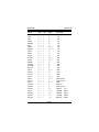
Table of Contents
1
Introduction to the Model 9000 . . . . . . . . . . . . 1
2
Getting Started Quickly! . . . . . . . . . . . . . . . . . 3
Steps . . . . . . . . . . . . . . . . . . . . . . . . . 3
Examples . . . . . . . . . . . . . . . . . . . . . . . 6
3
4
Commands . . . . . . . . . . . . . . .
:
Intel Hex Program . . . . . . . .
S Motorola Hex Program . . . . .
/
Tektronix Hex Program . . . . .
P Block Program . . . . . . . . . .
R Block Read . . . . . . . . . . . .
OI Intel Hex File Output . . . . . . .
OM Motorola Hex File Output . . . . .
OT Tektronix Hex File Output . . . . .
L List Formatted Output . . . . . . .
U Unerased (Blank) Check . . . . .
V Verify Erasure Check . . . . . . .
M Menu Selection . . . . . . . . . .
T Toggle Commands . . . . . . . .
TA IBM type Checksum . . . . .
TC Compare Mode . . . . . . . .
TE Echo Mode . . . . . . . . . .
TI Intelligent Algorithm Mode .
TQ QuickPulse Algorithm Mode
TN Checksum . . . . . . . . . .
TR Reset TC and TS Toggles . . .
TS Split Mode . . . . . . . . . . .
TB Byte Mode . . . . . . . . . .
’ ’ Reissue Command Prompter . . .
I
Identify Serial Device . . . . . . .
X Return Version . . . . . . . . . .
$ Abort to Command Prompter . . .
. . . . . . . . 9
.
.
.
.
.
.
.
.
.
.
.
.
.
.
.
.
.
.
.
.
.
.
.
.
.
.
.
.
.
.
.
.
.
.
.
.
.
.
.
.
.
.
.
.
.
.
.
.
.
.
.
.
.
.
.
.
.
.
.
.
.
.
.
.
.
.
.
.
.
.
.
.
.
.
.
.
.
.
.
.
.
.
.
.
.
.
.
.
.
.
.
.
.
.
.
.
.
.
.
.
.
.
.
.
.
.
.
.
.
.
.
.
.
.
.
.
.
.
.
.
.
.
.
.
.
.
.
.
.
.
.
.
.
.
.
.
.
.
.
.
.
.
.
.
.
.
.
.
.
.
.
.
.
.
.
.
.
.
.
.
.
.
.
.
.
.
.
.
.
.
.
.
.
.
.
.
.
.
.
.
.
.
.
.
.
.
.
.
.
.
.
.
.
.
.
.
.
.
.
.
.
.
.
.
.
.
.
.
9
10
10
10
11
11
11
12
12
12
12
13
14
14
14
14
15
15
15
15
15
15
16
16
16
16
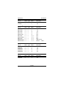
Diagnostics . . . . . . . . . . . . . . . . . . . . . . . 17
General . . . . . . . . . . . . . . . . . . . . . . . . 17
Fatal Error Codes . . . . . . . . . . . . . . . . . . . 17
Non-Fatal Errors . . . . . . . . . . . . . . . . . . . . 18
Page ii
Table of Contents
Overload Conditions . . . . . . . . . . . . . . . . . . 19
PGMX Communications Diagnostics . . . . . . . . 19
5
Interfacing Notes . . . . . . . . . . . . . . . . . . . . 21
Figure 5.1 . . . . . . . . . . . . . . . . . . . . . . . 22
6
Specifications . . . . . . . . . . . . . . . . . . . . . . 23
Making A Cable . . . . . . . . . . . . . . . . . . . . 24
7
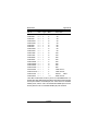
Hex Formats . . . . . . . . . . . . . . . . . . . . . . . 25
Intel Format . . . . . . . . . . . . . . . . . . . . . .
Data Record . . . . . . . . . . . . . . . . . . . .
End Record . . . . . . . . . . . . . . . . . . . .
Extended Address Record (MCS–86 hex format)
Start Address Record (MCS–86 hex format) . . .
Motorola Format . . . . . . . . . . . . . . . . . . . .
Comment Record . . . . . . . . . . . . . . . . .
Data Records . . . . . . . . . . . . . . . . . . .
End Record . . . . . . . . . . . . . . . . . . . .
Tektronix Format . . . . . . . . . . . . . . . . . . . .
Data Blocks . . . . . . . . . . . . . . . . . . . .
Termination Block . . . . . . . . . . . . . . . . .
Abort Block . . . . . . . . . . . . . . . . . . . .
Example: Data/Abort block . . . . . . . . . .
Example: Data/Termination block . . . . . . .
25
25
25
25
26
27
27
27
28
29
29
29
30
30
30
8
GHEX2 and STOHEX.EXE . . . . . . . . . . . . . . 31
9
PGMX . . . . . . . . . . . . . . . . . . . . . . . . . . 33
Installation of PGMX . . . .
Operation . . . . . . . . .
Examples . . . . . . . . .
Valid Options . . . . . . .
Examples . . . . . . .
Using Control–F . . . . . .
Definitions . . . . . . . . .
Valid Commands for PGMX
.
.
.
.
.
.
.
.
Page iii
.
.
.
.
.
.
.
.
.
.
.
.
.
.
.
.
.
.
.
.
.
.
.
.
.
.
.
.
.
.
.
.
.
.
.
.
.
.
.
.
.
.
.
.
.
.
.
.
.
.
.
.
.
.
.
.
.
.
.
.
.
.
.
.
.
.
.
.
.
.
.
.
.
.
.
.
.
.
.
.
.
.
.
.
.
.
.
.
.
.
.
.
.
.
.
.
.
.
.
.
.
.
.
.
33
34
35
36
36
38
39
40
Table of Contents
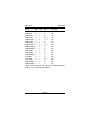
Examples . . . . . . . . . . . . . . .
Advanced Example . . . . . . . . . .
Batch file automation . . . . . . . . . . .
Error return codes for batch file processing
Other programs available . . . . . . . . .
10
.
.
.
.
.
.
.
.
.
.
.
.
.
.
.
.
.
.
.
.
.
.
.
.
.
40
42
42
43
44
Warranty And Service . . . . . . . . . . . . . . . . . . 45
Limited Warranty . . . . . . . . . . .
Service . . . . . . . . . . . . . . . .
PGMX Software License Agreement
License . . . . . . . . . . . . . . .
Term . . . . . . . . . . . . . . . . .
PGMX Limited Warranty . . . . . . .
Limitations of Remedies . . . . . . .
General . . . . . . . . . . . . . . .
A
.
.
.
.
.
.
.
.
.
.
.
.
.
.
.
.
.
.
.
.
.
.
.
.
.
.
.
.
.
.
.
.
.
.
.
.
.
.
.
.
.
.
.
.
.
.
.
.
.
.
.
.
.
.
.
.
.
.
.
.
.
.
.
.
.
.
.
.
.
.
.
.
.
.
.
.
.
46
46
46
46
47
47
48
49
Appendix A— General Usage . . . . . . . . . . . . . . 51
Generall Rules . . . . . . . . . . . . . . . . . . . . . 51
B
Appendix B— Cross Reference . . . . . . . . . . . . . 53
C
Appendix C— Baud Rate Defaults
D
Appendix D— Trademarks
. . . . . . . . . . . 81
. . . . . . . . . . . . . . . 83
Page iv
Table of Contents
—Notes—
Page v
Model 9000
Introduction
Chapter 1
Chapter 1, Introduction
Congratulations. You now have, what we believe to be, the most cost
effective and advanced eprom programmer on the market today. The
design philosophy used on the GTEK, Inc. Model 9000 allows for
simple future expansion of capabilities. All serial communications with
the 9000 is in printable ASCII characters and it supports Intel hex and
Motorola hex formats as well as simple block formats. Additionally, the
9000 supports the MCS–86 extended hex format, and Motorola’s S
record format with features for automatically split programming 2
Eproms for use in a true 16 bit data path. Resident features include
facilities for making source to eprom content comparisons, erasure
checks, formatted device listings, menu driven device selection, and
more.
The 9000’s interrupt driven type ahead buffer allows it to program and
verify in real time, while data is being sent (transparent to the user,
whose sole responsibility is to send and receive data).
Three user selectable algorithms are available, a standard 50ms
program cycle with post verification, adaptive algorithms and QuickPulse™ algorithms. Adaptive algorithms may be either by Intel
(inteligent™) or others such as Fujitsu® (Quick Pro™), Xicor®,
Motorola, etc.
Adaptive algorithms typically offer a six fold improvement in programming time over the standard algorithm. QuickPulse algorithms are
about 10 times faster on the 9000 over the GTEK, Inc. Model 7228
adaptive algorithms. Extended diagnostics pinpoint the cause of any
errors.
Throughput is greatly enhanced by using parts which can be
programmed with the QuickPulse algorithm. QuickPulse can program
an Intel P27256 in 24 seconds. The adaptive algorithm can program
the same part in 164 seconds. The standard algorithm, (if it were
available for this part) would take 1638 seconds!
The Model 9000 may be used without handshaking, or with
XON/XOFF or hardware CTS/DTR handshake. Baud rate selection is
done automatically through your interface program or PGMX. The
9000 default baud rate is presettable for those not using PGMX (see
appendix C).
Page 1
Chapter 1
Introduction
Model 9000
PGMX is an optional interface program that runs on an IBM PC,
XT, AT or PS/2 (all models) and allows you to read and program
eproms on the Model 9000 at baud rates up to 57,600. Appendix B
contains a cross–reference of Manufacturer versus menu selection to
use for the (E)(E)Prom types that may be programmed by the 9000.
All voltages and pin configurations are set up by the onboard
microprocessor and no personality modules are required. ROMs may
be read safely only with certain eprom selections, such as i27512,
i68766, F27C64, F27C256 and 27C32. See Appendix A.
Page 2
Model 9000
Getting Started Quickly
Chapter 2
Chapter 2, Getting Started Quickly
Note that when it says to insert a part in any of the below examples,
you should put the part in the Textool socket so that the notch on the
part is towards the TOP of the 9000 where the handle is on the socket.
The bottom of the socket (where pin 12 and 14 go) is marked “BOTTOM”. AND close the handle!
Steps
First, apply power to the 9000. Always make sure that there is no chip
in the socket on the 9000 before applying power. We suggest you use
a power strip on a multiple outlet with an on-off switch to turn the power
on to all your equipment at one time. You are less likely to damage any
eprom that way. It doesn’t hurt to leave power applied to the 9000 for
long periods of time, and it draws little power when idle.
When the 9000 boots for the first time during the day, and you run your
interface program PGMX, your default eprom type will be null, and the
default prompter will indicate “<xxxx>”. This reminds you to make an
eprom type selection on power up. After that, whatever you have set
for an eprom type will remain selected until the 9000 loses power or a
new eprom type is selected.
Look up the eprom part number of the chip you will be programming
in the appendix of this manual, or on the program disk.
The eprom part number will usually be prefixed with a manufacturers
symbol or letters, with a number following, usually starting with a “27”,
like iP27256 or MBM27C256. There may be a letter after the “27”
number like 2764A or 2716B.
This letter will affect what menu selection to make for that eprom type,
so always look for that extra letter! It will usually be an A, B or C.
Determine the setting that will be used from the part listing in the
appendix of this manual or from any lists on the program disk.
At this point, or at any time after you apply power to the 9000 for that
matter, you can communicate with the 9000. Use the PGMX program
to do this. See the section on PGMX for specific details on initializing
PGMX and communications. If you can’t use PGMX on your computer
for some reason, you can use any “terminal emulator” or modem
program. You lose some convenience when you have to do this, but
Page 3
Chapter 2
Getting Started Quickly
Model 9000
all the same commands are available. See the Interfacing and Commands chapter. Also see the PGMX chapter. See Appendix C for
default baud rates.
Remember that the menu selection of the part determines what
“programming algorithm” is used and the “programming voltage”. The
programming algorithm is the set of instructions built into the 9000 that
determine what voltages to put where, when. The programming voltage is the level of elevated voltage that is to be applied to the pin
selected by the programming algorithm.
Remember also that selection of the wrong part number might cause
you to destroy your eprom.
Set the eprom menu selection (while communicating with the 9000
with PGMX) by typing the letter M plus the letter indicated by the
selection. If you already know what part you are using but forgot what
selection to make, type M plus a <cr> to get a menu of parts to select
from. Make sure you know what you are selecting if you use the M<cr>
method of selecting parts. It is easy to find say a 27128 in the menu,
but if you don’t know that there are 3 different types of 27128’s then
you have a 33% chance of making the right selection. As it turns out,
there are 3 selections for 27128; the first uses 21 volts. The second
uses 12.5 volts, and the third uses the 27256 algorithm and 12.5 volts
(National 27CP128). If you know your part uses 12.5 volts, you can
simply make that 12.5 volt 27128 selection (if you know which selection
is the 12.5 volt part, selection “2” in the case of a 12.5 volt part and not
“F”).
Once the menu selection is made, it will stay that way until you lose
power or you make another selection.
If the Busy led is off, you may now load the 9000 with your part.
Caution!
If the Busy led is on, power is applied
to the socket, and removing or installing an eprom at that time will damage
it and/or the 9000. Always make sure
the power is on and the Busy led is
OFF before removing and installing
an eprom.
Page 4
Model 9000
Getting Started Quickly
Chapter 2
Now you can check the part to see if it is blank. You don’t have to do
this, but if an error occurs during programming you will wonder whether
or not the part was really erased or not.
To verify through PGMX, type the letter U and then return(<cr>). This
will cause the 9000 to check the entire part. If you only want to check
part of it, type the letter U and then the starting and ending addresses
to check. The Busy led will come on indicating that the 9000 is doing
something. After a short period of time, the Busy led will go off. If the
eprom is not erased, the 9000 aborts to the command mode with an
error message *NE ERR @nnnn, where nnnn is the address that
contains data. The 9000 will return to the command state without
issuing any error message if the part is blank.
Type Control – F (hold down the control key and press the letter F) and
you will get a prompter to enter command line. A minimum command
line consists of a <cr>, which will return you to the 9000 commmand
prompter. To program a file, the minimum command line would consist
of a filename and a <cr>. You can also specify options on the command
line, but probably not when you are programming manually like this.
To program from an Intel Hex file from the Control–F “enter command
line” prompt, enter the file name (format: filename.HEX). You don’t
have to specify an extension unless you want to program from a
BINARY file (format: filename.ext). In most cases it is probably an Intel
Hex file you are using. Remember the interface program PGMX can’t
handle any other format than Intel Hex or Binary.
After you enter the filename, and you hit <cr>, PGMX will look for a file
by the name you specified on the disk and begin sending it to the 9000.
It will show only the load address that is being processed (in Ascii–Hex
numbers), or the number of bits programmed in the Binary format
(decimal numbers).
If an error occurs while programming any particular chip, PGMX will
abort sending the file and issue the error message that was sent from
the 9000. Control is returned to PGMX or DOS (depending on where
you started from, in this case from PGMX).
See the Diagnostics section for Overload information.
At this point, you may then reload the 9000 and begin the process
again.
Page 5
Chapter 2
Getting Started Quickly
Model 9000
Examples
Example to read a 2764 made by Hitachi (21 volt pgm voltage) and
then program an Intel 2764A. Remember that a 2764A is a 12.5 volt
part and may as well be considered as a completely different part
number even though generically (in operation) they are identical parts.
BUT they don’t program the same!!!
1. Apply power to the 9000 before you insert any parts.
2. Look for the part number in the appendix. It says to use Menu
Selection number “E”.
3. Communicate with the 9000 if you are not already (at the DOS
prompt type PGMX<cr>). Type “ME” at the PGMX eprom prompt.
4. Insert the Hitachi 2764 into the Textool socket.
5. Press ^F (hold down the control key and press the letter F) to get
the “enter command line ––>” prompter and type:
Enter Command Line ––>FILENAME [R<cr>
FILENAME is what you want the file to be called on the disk. It will
automatically have an extension of “.HEX”. <cr> means to press
the “enter” or “return” (↵)key. “R” means to read the file in the Intel
Hex format (OI to the 9000). PGMX will automatically open the disk
file (if one exists already, it will not let you destroy it) and cause the
9000 to begin sending the content of the eprom in the Intel Hex
format, which is then put into the disk file. When the 9000 has
finished sending, PGMX will close the file and return you to the
eprom type prompter.
6. Remove the Hitachi part and insert the Intel part.
7. You must now change the eprom type! Looking it up in the
manual says to use “1” so type “M1” to select “q2764A>”. It is ok to
use the “q” or “i” (toggles) on any brand part (at the eprom type
prompt), but you are more likely to get an error programming using
the “q” in the prompter if it is not an Intel part. Since this example
uses an Intel part, we won’t change it, but if for instance it was a
GI or AMD part, you might want to type “TI” to select the adaptive
programming algorithm (i2764A) rather than the QuickPulse algorithm (q2764A).
8.
Page 6
Model 9000
Getting Started Quickly
Chapter 2
This part has to be blank, so press U<cr> to see if it is blank. If the
part is not blank, an error message will be issued, like *NE err
@00000 Repeat with another part until you find one that is blank.
9. If it is blank, press ^F (as before) to get the “enter command”
prompter and type:
Enter Command Line ––>FILENAME<cr>
This will cause PGMX to look for FILENAME.HEX on the disk and
begin sending it to the 9000, which programs the part.
10.If the part fails during programming, an error message of what went
wrong and the location (like *WP err @0000) will be issued.
Otherwise, if programming is completed without any errors, the part
is properly programmed AND verified at this point. You could have
also issued a command to give you a checksum at the same time
from the previous command line or you can type “TN<cr>” right now
to get a checksum of the part.
Enter Command Line ––>FILENAME [TN<cr>
or
<q2764A>TN<cr>
EXAMPLE
Example programming chips from within PGMX. When you are
through programming from the previous example, you are returned to
the 9000 command prompter. We will now program a number of Fujitsu
27C64s.
1. The menu command for the Fujitsu 27C64 is “O” (looking it up in
the menu) but you can program that part adaptively (recommended
by the appendix) by selecting “E”.
2. Enter the following commands after inserting the part to be
programmed. Type Control–F to enter the automation mode and
enter your commands:
<q2764A>^F
Enter Command Line ––>FILENAME [tn,u,me<cr>
In order, this sends the menu command “ME” and then the “U”
command, programs the part from FILENAME, and then calculates
a checksum of the part just programmed. The prompter will have
changed to <i2764>_.
Page 7
Chapter 2
Getting Started Quickly
Model 9000
3. Part is now programmed. If there were any errors during the
process, PGMX will abort with an error message back to the 9000
command mode. Be sure to look at the checksum to see if it is what
it is supposed to be.
4. To repeat the process, insert a new part and type Control–F and
then press the “F3” function key, which will give you the previous
command line that was issued which was FILENAME [tn,u,me.
Pressing <cr> now will cause the process to begin again.
You SHOULD read the rest of the manual to get specific details about
some of the operations performed above, specifically the COMMANDS chapter, the DIAGNOSTICS chapter and the PGMX chapter.
Page 8
Model 9000
Diagnostics
Chapter 3
Chapter 3, Commands
When you use the 9000 with PGMX there are 2 different forms of
commands you can issue. One is for PGMX and the other is for the
9000. See the PGMX chapter for commands for PGMX. This chapter
explains commands for the Model 9000.
PGMX also has 2 modes— the “interactive” mode and the “automation” mode. Interactive mode allows you to communicate with the
9000 to issue the following commands to the console, and the automation mode allows you to automatically issue some of these same
commands in the proper sequence to the 9000 to “read” an eprom
to a disk or program an eprom from a disk with various options. All
of the commands listed for the 9000 can be issued interactively for
PGMX. Commands that are handled automatically by PGMX (in the
automation mode) in the paragraphs below, will have the word
“automated” at the end of the explanation.
The following are the commands that can be used on the 9000. Most
people that use PGMX will not have to use any of these commands
except for the “Toggle” and “Menu” commands. All of the commands can be executed from most kinds of terminal emulators or
modem programs.
:
Intel Hex Program
When the model 9000 is in the command state, receipt of a colon
is interpreted as the lead character in an Intel hex record. The
9000 automatically enters the program mode and programs the
data contained in the hex record at the address specified in the
header of the hex record. The check sum is verified at the end of
the hex record and the model 9000 then returns to the command
state but does not reissue the command prompter unless the
record happened to be the END record. This is done in anticipation of another hex record, i.e., all characters from the hex file,
sent to the Model 9000 will be echoed back to the user with no
additions or deletions. Power to the programming socket is not
turned off until an end record or error occurs.
If a data error, checksum error, or syntax error occurs during the
file transfer, the 9000 will issue the appropriate error message and
abort back to the command state.
Page 9
Chapter 3
Diagnostics
Model 9000
See the section on toggles and hex formats for clarification on
how to program two devices for device use on a true 16 bit data
bus. The segment base address register, maintained by the 9000,
is automatically cleared when the end record is detected, or if
any other command is executed other than the Intel Hex command. Remember that you do not have to “split” a hex file if you
have a 27210 (16 bit data path). AUTOMATED.
S
Motorola Hex Program
This command works the same as the Intel Hex program command under other communication software, except that the
format is the Motorola S record format. Records may be of type
S0, S1, S2, S3 OR S9.
/
Tektronix Hex Program
This command works the same as the Intel Hex program command under other communication software. When the model
9000 is in the command state, receipt of a forward slash is
interpreted as the lead character in a Tektronix hex block. The
9000 automatically enters the program mode and programs the
data contained in the hex block at the address specified in the
header of the hex block. The checksums are verified at the end
of the hex block and the 9000 then returns to the command state
but does not reissue the command prompter unless the block
happened to be the termination block. This is done in anticipation
of another hex block, i.e., all characters from the hex file, sent to
the Model 9000 will be echoed back to the user with no additions
or deletions.
P
Block Program
Sending A “P”, followed (optionally) by an ascii–hex address, and
a valid delimiter puts the 9000 into the block program mode. Once
in this mode, ascii–hex data to be programmed into the eprom is
sent. The data may be a continuous stream of characters or
groups of 2 characters (2 characters is 1 data byte to the 9000)
separated by delimiters (space, comma, return, line–feed or
dash).
This mode is terminated when you send the 9000 a dollar sign
($), or if an error occurs. Use this command to program one byte
or a block of bytes at any given location. All characters are
echoed back to the sender as they are removed from the buffer
in the 9000, except for null, Xon and Xoff. As you program
locations in order, the address is automatically incremented. The
following example programs locations 444h and 445h:
Page 10
Model 9000
Diagnostics
Chapter 3
Example:
<2716>P444,33 23$
<2716>_
This is PGMX’s binary program mode. AUTOMATED.
R
Block Read
Don’t confuse this command with PGMX’s “R” command. The R
command, followed optionally by beginning and ending addresses, causes the Model 9000 to output a continuous string of
ASCII–HEX characters between the specified addresses. If no
addresses are specified, the 9000 will output the entire contents
of the selected device. The R command may be aborted at any
time by sending a dollar sign, “$”, to the 9000. The following
example uses the eprom programmed in the example of the “P”
command. Example:
<2716>R444,445<cr>
3323
<2716>_
Note: The R command is primarily for automated reading of
eproms. The above example will actually appear as the example
below. The data output overwrites the command line unless your
terminal is in an auto line feed mode. AUTOMATED.
Example:
33236>R444,445
<2716>
OI
Intel Hex File Output
This command “reads” an eprom and sends the data in the Intel
Hex format to the computer. The OI command has the same
command syntax as the 9000’s “R” command. It differs in that
the 9000 will output the device contents as an Intel hex file,
including the end record, between the specified addresses inclusive or if no addresses are specified, the entire device. Again,
the command may be aborted if desired with a dollar sign, “$”.
AUTOMATED.
OM Motorola Hex File Output
This command functions precisely the same way the OI command does, except that the output is in the Motorola S record
format.
OT Tektronix Hex File Output
Page 11
Chapter 3
Diagnostics
Model 9000
This commandworks the same way as the OM and OI command
does, except that the output is Tektronix hex format.
L
List Formatted Output
The L command outputs data between optionally specified addresses, inclusive, in a formatted fashion similar to many dump
utilities. If no addresses are specified, the entire contents will be
listed and the command may be aborted with the dollar sign, “$”.
Each line of the listing includes the beginning address in Ascii–
hex, sixteen data bytes in Ascii–hex and the Ascii representation
of the data. Non printable bytes are replaced with periods in the
ASCII representation field.
Example:
<2716>L90,AF<cr>
0090 4845 4C4C 4FFF FFFF FFFF FFFF FFFF FFFF HELLO...........
00A0 FFFF FFFF FFFF FFFF FFFF FFFF AA55 AA55 ................
<2716>_ [prompter indicates end of command]
Note: Unlike the R, OI, OT and OM commands, the L command
will output a carriage return and line feed at the beginning of the
listing. This is because the L command is primarily used when
the host is functioning as a terminal and it would be irritating to
have the first line of the listing overwrite the command line.
AUTOMATED.
U
Unerased (Blank) Check
The U command checks an entire part for blank if a starting and
ending address is not specified. If a part is not erased, an error
message saying * NE err @nnnn will be issued with a return to
the command prompter. An empty socket looks like a blank part
unless you have one of the MCS-48 family selected. The command can be aborted with a dollar sign, “$”. AUTOMATED.
V
Verify Erasure Check
The V command checks the cells between the optionally
specified addresses for erasure, FF’s or 00’s as the device type
dictates. If no addresses are specified, the entire device is checked. If a cell is not erased, a non–fatal error message is issued
consisting of the data and the address. The process continues
until the end address is reached or the command is aborted with
a dollar sign, “$”. The following example uses the same eprom
used in the P and R command examples. AUTOMATED.
Example:
Page 12
Model 9000
Diagnostics
Chapter 3
<2716>V<cr>
33 @ 0444
23 @ 0445
<2716>_
M
Menu Selection
You may select the device you will be working with in 2 ways. The
current device type always becomes part of the command
prompter. Selecting a device establishes the programming algorithm to be used, as well as the device pinout, proper programming voltage and prompter.
1) Type an “M” and then the appropriate code letter. Example:
<q27011>ME
<i2764>_
2) Type an “M< cr> ” to get a menu of parts to select from:
Software Selection Method:—This is an example only!
See the Appendix section on Manufacturer’s cross reference to cor<i2764>M<cr>
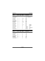
EPROM SELECTION MENU —
NMOS
NMOS
CMOS
EEPROM
W/ADAPT
A–2758
G–AM2716B L–27C16
P–5213
R–874x–1K
B–2716
H–AM2732B M–27C32
Q–X2816A S–874x–2K
C–2732
I–2532
N–MC6716 X–48016
T–874xH–1K
D–2732
J–2564
O–F27C64 Y–I2816A U–874xH–2K
E–2764
K–68766
0
/–I27C64 3–I2817A
V–8751
1–2764A
@–CY7C292 8–F27C256 9–X2864A
$–87C51
F–27128
+–TI2532A 6–I27C256 (–AM9864
W–8755
2–27128A &–W292/43 5–F27C512 4–X28256
!–874xAH
Z–27256
“–CY7C292A {–27CX321 .(–AM2864B ^–8752AH
7–27512
%–F27256 }–27CX641 .X–NMC9346 ?–87C51FB
#–27513
.&–WS57C49
=–27011
."–AM27C291
ENTER SELECTION—2<cr>
<q27128A>_
relate your part number with the appropriate eprom type selection.
AUTOMATED.
TA Toggle IBM type Checksum
Page 13
Chapter 3
Diagnostics
Model 9000
The TA command (Beginning with Version 5.24 of the 9000 and
Version 9.33 of PGMX) allows you to calculate an 8 bit checksum
of “00” to be programmed at a specified location in your eprom.
If no location is specified (TAnnnn< cr> ) then the byte is
programmed at the last location in the eprom. What happens is
TA will calculate an 8 bit number to add to the eprom to make the
16 bit checksum “nn00h”. The LSB of the checksum is 00. If the
checksum is already 00 then no programming is done, otherwise
the TA command will attempt to program the specified location
in your eprom. All normal programming rules apply.
TC Toggle Compare Mode
The TC toggle command is used to turn the compare mode on
and off. When in the compare mode, the command prompter is
prefixed by a lower case c. The compare mode is used to
compare the contents of a device against that of a source file.
Interactively, a TC will cause the compare mode to be set, and
the next TC command will reset the compare mode. In the
automation mode, a TC on the command line will always cause
the compare mode to be set only. To reset compare mode use
the TR command.
To use the compare mode, issue a programming command as if
you were going to program the device. Instead of programming
the device, the 9000 will make a comparison of the source byte
to the contents of the device. If they are not the same, the
comparison error will cause a * CP err @nnnn error message to
be issued. See Diagnostics Section for details. AUTOMATED.
TE Toggle Echo (On/Off)
The TE command allows a person to write their interface software
more efficiently so that it does not have to handle receiving any
characters during the program process. As soon as the command is issued (ΤΕ ) nothing is echoed or sent back to the
console. As long as valid commands or data are being sent to
the 9000, nothing is echoed or sent back. As soon as an error
occurs, or any time the “X” command is issued, the 9000 reverts
back to sending all characters. AUTOMATED.
Page 14
Model 9000
TI
Diagnostics
Chapter 3
Toggle Intelligent Algorithm Mode
The TI command turns the intelligent programming algorithm on.
Typing TI for a device that does not use the intelligent algorithm
will cause an error message * UV err @nnnn to be issued. Some
parts default to the intelligent algorithm and will give an error
message if TI is issued for that part. AUTOMATED.
TQ Toggle QuickPulse Algorithm Mode
The TQ command selects the “quick” algorithm for the selected
part. Some part types default to the QuickPulse algorithm and is
the only algorithm supplied for that part, so typing TQ on those
will result in a * SN err or a * UV err. AUTOMATED.
TN Toggle Checksum
This command is handled by PGMX during the interactive or
automation mode (issued after part is programmed). The TN
command is used to generate a 16 bit checksum from the data
in the eprom. This is the 16 bit sum of all the (8 bit) Data bytes
added together without carry. You can make a checksum between any two addresses by specifying the Hex starting and
ending addresses. The checksum is calculated and then output
to the user. See examples of this in the PGMX chapter.
AUTOMATED.
TR Reset TC and TS Toggles
The TR command resets the compare mode and the split mode
toggles. You may also reset these and any other toggles set by
reselecting the part type with the Menu command. AUTOMATED.
TS Split Mode
The TS command puts the 9000 into a split mode used for
programming 2 eproms whose intended destination is for use in
a true 16 bit data path. While in the split mode, the command
prompter is prefixed by either a lower case h or l indicating high
(odd address) or low (even address) byte respectively. It should
be noted, that if a programming error should occur while in the
split mode, that the address of the error given by the 9000 will be
the address within the eprom being programmed, not the address in the hex file. See also the TB command. AUTOMATED.
TB Byte Toggle
The TB command is used in conjunction with the split mode (TS)
to target the selected device for the high (odd) bytes or low (even)
bytes from an Intel Hex or Motorola S record source file.
Page 15
Chapter 3
’ ’
Diagnostics
Model 9000
Reissue Command Prompter
Used in PGMX’s interactive mode only. Sending a space (ascii
32 char) to the 9000 causes it to reissue the command prompter.
I
Identify Serial Device
The Model 9000 will issue data used by PGMX in determining the
model and version. AUTOMATED.
X
Return Version
The X command is used to issue a Logon message and the
prompter. The X command will return the following:
<2716>X
GTEK, INC.
MODEL 9000 Vx.xx
COPYRIGHT 1987
<2716>_
When ordering accessories from GTEK, please remember to
include the version and serial number. AUTOMATED.
$
Abort to Command Prompter
A $ sent to the 9000 will abort most operations to the 9000
command prompter. AUTOMATED.
Page 16
Model 9000
Diagnostics
Chapter 4
Chapter 4 Diagnostics
General
Most diagnostics are handled by PGMX. The person that is using
PGMX need only be concerned with the meaning of any error message that is issued by PGMX. Other information here is for persons
not using PGMX.
1) All error codes to be issued by the 9000 are preceded by an asterisk,
(* ). This makes error trapping very easy.
2) When a non–fatal error occurs (such as when you are using the V
command), no error message is issued and you are returned to the
9000 command prompter when the command completes.
3) FATAL errors are output on a real time basis, that is, they are output
as soon as they are detected, and the programmer returns to the
command state.
4) Fatal Error codes include the address at which the error occurred.
Fatal Error Codes
* WP ERR @ nnnn Won’t Program error: This error is issued only
in the event that the 9000 discovered that it could not change the
data in the chip, even though the bits were not already set. When
using the QuickPulse algorithm, you will not get any * NE errors, only
* WP since the 9000 does not “pre-read” the cells prior to programming.
* NE ERR @ nnnn Needs Erasing error: This error is issued only in
the event the 9000 discovered that it could not change the data in
the chips, and the bits were already set. You will never get an NE
error with the QuickPulse algorithm, because the 9000 does not pre–
read cells to be able to tell that a bit was not set previous to
programming with the QP algorithm.
* CP ERR @ nnnn ComParison error: Issued during comparisons
and verifies (U command).
Page 17
Chapter 4
Diagnostics
Model 9000
* DT ERR @ nnnn DaTa error: The character that was sent is not
valid hex data. (0–9 or A–F) This error message is issued as soon as
it happens.
* CS ERR @ nnnn Check Sum error: Issued if a checksum error is
detected in a hex record. Only applies to Intel, Motorola, and
Tektronix hex format program commands. This error message is issued as soon as it happens
* SN ERR @ nnnn SyNtax error: An invalid command was issued to
the programmer. This error message is issued as soon as it happens. See COMMANDS section.
* ST ERR @ nnnn STack error: FIFO overflow. Reduce baud rate or
see the interfacing section for handshaking methods. (The 9000 can
take data at 300 bps with no handshake.) PGMX users may not be
using the right RS-232 cable. This error message is issued as soon
as it happens.
* UV ERR @ nnnn Un-aVailable error: Issued in the event the user
tries to use a function of the programmer that is not available for that
particular device. This error message is issued as soon as it happens.
Non-Fatal Errors
These errors are considered non fatal in that the process continues,
that is, it makes you aware that there may be a problem, but you
don’t want to stop right now because it may not be an error. One example is when you are using the V command, and you find some
non blank locations. You may have intended that those locations
have data, so the 9000 continues, but makes you aware of those
locations by issuing a message showing data and address.
Overload Conditions
If a programming voltage overload condition occurs, the 9000 will
not say “OVERLOAD”! The 9000 will not be damaged unless the part
is shorted to the data bus or address lines and you keep trying the
process several times in a row before realizing the part will not program.
The key indication is a * NE error or a * WP error. Do something other
than trying to immediately program the part again without checking
the menu selection you have made or erasing the part.
Page 18
Model 9000
Diagnostics
Chapter 4
Remember that the Textool socket may have programming voltage
(Vpp) applied to various pins even during such commands as a List
command or Read command. Some algorithms on the 9000 use the
eprom “verify read” mode, which means that programming voltage
is applied during a “read” of the part. This will usually damage a part
such as a 2764A if you have the 2764 algorithm selected! Some
selections are always safe to use to just read a part if you are not
sure what selection to use. F27C64, F27C256 and 27512 are usually
safe (ON READS ONLY!).
You can use a 27512 selection to read any 28 pin part (including
ROMS). By noticing what locations within the address range have
duplicated data, or where data appears at all, you can usually determine what size the target part is. If you know where certain data is
supposed to appear, you can determine if it has masked chip select
lines.
PGMX Communications Diagnostics
Please refer also to the chapter on PGMX. PGMX can detect various
problems with the serial channel during communication. Error messages usually have a symptom and a diagnosis message, such as
“(beep) Framing Error (beep) Overrun error! Reduce baud rate”. Follow the directions specified by the error message.
Persons using PGMX and making their own cable will most likely run
into the Framing error and the Overrun error. The cause of this is
usually they don’t have their CTS line on the 9000 hooked to the
DTR line on the computer. The computer can’t tell the 9000 to stop
sending. Stack errors are usually caused by the reverse, CTS on the
computer is not hooked to DTR on the programmer. The 9000 can’t
tell the computer to stop sending.
The second most frequent problem people run into is the fact they
can’t believe their computer can’t receive data at 57,600 baud. It
takes a fast computer (8 MHz AT or better) to handle data coming in
at that maximum rate. You will usually get framing errors or overrun
errors when this happens. The cure is to reduce the baud rate. Most
PC’s and XT’s (4.77 MHz) can handle data at 9,600 baud without
much difficulty.
Page 19
Chapter 4
Diagnostics
Model 9000
The problem is compounded when a person runs programs in the
“background”. TSR programs like SIDEKICK and others steal time
during interrupts or key presses. This means you have less time to
be able to receive a character.
A poorly designed TSR program running at the same time may
prevent interrupts from being serviced and you may even miss characters (which is always fatal) when you are “reading” an eprom.
Programming eproms is less critical, since the transmit side of
PGMX is not interrupt driven. This means the error message you
receive about missed characters is only the echo of what was sent
to the 9000. However, if that character was an asterisk (* ), you might
miss the error message that follows. PGMX will eventually “time out”.
Unless you “fix” the problem by reducing the baud rate or running
without the TSR programs installed, it might happen again.
Page 20
Model 9000
Interfacing Notes
Chapter 5
Chapter 5, Interfacing Notes
The Model 9000 is surprisingly easy to interface and there are
several methods of handshaking which can be utilized if it is desired
to operate at the higher baud rates. The following section describes
some of the methods. Of course if you are going to use our interface
program PGMX, you can skip this chapter.
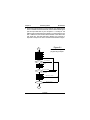
1. Software handshake. This is perhaps the easiest method of all.
When you begin to send data to be programmed, send the first byte
but don’t wait for it to be echoed. That would effectively cut your
communication rate in half. Instead, send the second byte, receive
the first, send the third byte, receive the second, etc. This technique
will allow you to program as fast as the algorithm in use permits.
Some devices program faster, some slower! See an example of this
in Fig. 5.1.
2. CTS/DTR hardware handshaking. The Model 9000 is configured as
data terminal equipment, which means that the CTS (clear to send)
line is an input to the programmmer which when pulled low forces
the programmer to stop sending. On the other hand, the DTR (data
terminal ready) line is an output from the programmer, which will go
low when the buffer is about 50% full and high again when the buffer
is about 38% full. If you are using hardware handshake and the DTR
line goes low, you should stop sending to the 9000 within about 2
character periods (before XOFF is sent). The RTS line is pulled high
whenever the programmer is plugged in. See Specifications for
Cable.
3. Xon/Xoff software handshaking. If you do not monitor the DTR line,
the 9000 will transmit an Xoff character if the buffer gets to be about
63% full. If an Xoff has been sent, an Xon will be sent when the buffer
level drops to about 25% full. Likewise, when the programmer is
sending you data, you may send an Xoff character, which will stop
the programmer from sending until it receives an Xon character.
Xon’s and Xoff’s, are not put into the buffer, but are processed as
soon as they are received. Even if you don’t use Xon/Xoff handshaking, you will find it useful when using the L, list command, to stop
and start the data flow to your screen. Xon and Xoff are the keyboard
equivalents of control–Q and control–S respectively.
Page 21
Chapter 5
Interfacing Notes
Model 9000
4. Please note that the 9000 may communicate at many different baud
rates. To initialize at the new baud rate, send the 9000 a break signal
(set the output data line on your computer to + 12 volts) for 100
milliseconds, set the break to normal again (–12 volts). Wait for more
than 1 millisecond, then send an 80H character to the 9000 at the
new baud rate. The 9000 will begin reissuing the prompter in
response to the space or return command when locked on again.
Figure 5.1
start
Flowchart showing a
programming example.
open file
get character
send character
get character
Yes, char is eof
is char = eof?
No, char is not eof
send character
receive character
No, not an asterisk
is char * ?
display character
Yes, char is an asterisk
display character
char is not > or is eof
receive character
display character
No, char is not a >
is char > ?
Yes, char= >
end
Page 22
Model 9000
Specifications
Chapter 6
Chapter 6, Specifications
DIMENSIONS: ( H x W x D )
3.0" x 5.3" x 6.8"
(77mm x 133mm x 180mm)
POWER:
120VAC, 60HZ, 10 VA (240Vac, 50Hz, option)
INTERFACE:
DB25P - data terminal equipment (see below).
DATA WORD:
1 Start, 8 Data, 1 Stop, No parity
BAUD RATE:
Auto select 300–9600, 19200, 28800, 57600
Jumper Selectable 300, 1200, 2400, 9600, 19,200
(Rates above 9600 depend on your computer being able to keep up)
WEIGHT:
3 Pounds (2.4 KG)
OPERATING ENVIRONMENT:
45 - 95 DEG F. (7 - 35 DEG C.)
5% TO 95% non-condensing relative humidity
Page 23
Chapter 6
Specifications
Model 9000
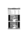
Making A Cable
From the model 9000 (> is output from 9000) DTE, to the computer (<
computer) DTE or DCE.
9000 DTE
to
DTE
or
1- Equip Ground (EG)
> <
1 (EG)
2- Transmit Data (TXD)
>
3 (RXD)
3- Receive Data (RXD)
<
2 (TXD)
4- Ready To Send (RTS)–not used >
6 (DSR)
5- Clear To Send (CTS)
<
20 (DTR)
6- Data Set Rdy (DSR)– not used >
4 (RTS)
7- Signal Ground (SG)
> <
7 (SG)
8—Carrier Detect (CD)–not used
<
4(RTS)
20- Data Term Rdy (DTR)
>
5 (CTS)
is output from
DCE
1 (EG)
2 (TXD)
3 (RXD)
4 (RTS)
5 (CTS)
6 (DSR)
7 (SG)
8 (CD)
20 (DTR)
1 EG
1 EG
2 TXD
2 TXD
3 RXD
3 RXD
4 RTS
4 RTS
5 CTS
5 CTS
6 DSR
6 DSR
7 SG
7 SG
8 CD
8 CD
20 DTR
20 DTR
9000 Programmer (DTE)
(female)
1 EG
IBM 25 pin or 25 pin DTE connector
(female)
HOOK TO CABLE SHEILD
1 CD
2 TXD
2 RXD
3 RXD
3 TXD
4 RTS
4 DTR
5 CTS
5 SG
6 DSR
6 DSR
7 SG
7 RTS
8 CD
8 CTS
20 DTR
(NC)
9000 Programmer (DTE)
(female)
9 RI
IBM 9 pin or DTE 9 pin connector
(female)
Page 24
Model 9000
Hex Formats
Chapter 7
Chapter 7, Hex Formats
Intel Format
Data Record
Byte Number
1
2—3
4—5
6—7
8—9
10—x
x+ 1 – x+ 2
x+ 3 – x+ 4
Colon (:)
Number of binary data bytes
Load address, high byte
Load address, low byte
Record type
Data bytes, 2 ascii–hex characters
Checksum, two ascii–hex characters
CR,LF
End Record
Byte Number
1
2—3
4—7
8—9
10—11
12—13
Colon (:)
Record length, must be “00"
Execution address
Record type
Check sum
CR,LF
Extended Address Record (MCS-86 hex format)
Byte Number
1
2—3
4—7
8—9
10—13
14—15
16—17
Colon (:)
Record length, should be “02"
Load address field, should be “0000"
Record type, must be “02"
USBA
Check sum
CR,LF
Page 25
Chapter 7
Hex Formats
Model 9000
Start Address Record (MCS-86 hex format)
Byte Number
1
Colon (:)
2—3
Record length, “04"
4—7
“0000"
8—9
Record type, “03"
10—13
8086 CS value
14—17
8086 IP value
18—19
Check sum
20—21
CR, LF
The checksum is the two’s compliment of the 8-bit sum, without carry,
of all the data bytes, the two bytes in the load address, and the byte
count.
Example:
:03012300010203D3
In the above example add 3 + 1 + 23h + 0 + 1 + 2 + 3 = 2Dh. The
total of the above bytes is 2Dh. If you do a two’s compliment on the
number the result is D3h which, you will notice is the checksum. A
simple visual way of doing this is to write the number in binary, then
invert each bit. After you do that, add 1 to it and that is the checksum:
00101101 = 2D
11010010 = D2 (inversion or negation)
+1 = add 1 for 2’s compliment
11010011 = 2’s compliment checksum.
Page 26
Model 9000
Hex Formats
Motorola Format
Comment Record
Byte Number
1—2
3—n
x+ 1—x+ 2
“S0"
Comment field
CR,LF
Data Records
Byte Number
1—2
3—4
5—6
7—8
9—x
x+ 1—x+ 2
x+ 3—x+ 4
“S1"
Number of data bytes + 3.
Load address, high byte.
Load address, low byte.
Data bytes, 2 characters each.
Checksum.
CR,LF.
Byte Number
1—2
3—4
5—10
11—x
x+ 1—x+ 2
x+ 3—x+ 4
“S2"
Number of data bytes + 4. (2 characters)
Load address, 24 bits (6 characters)
Data bytes, 2 characters each.
Checksum (2 characters).
CR,LF.
Byte Number
1—2
3—4
5—12
13—x
x+ 1—x+ 2
x+ 3—x+ 4
“S3"
Number of data bytes + 5.
Load address, 32 bits (8 characters)
Data bytes, 2 characters each.
Checksum
CR,LF.
Page 27
Chapter 7
Chapter 7
Hex Formats
Model 9000
End Record
Byte Number
1—2
“S9"
3—4
CR,LF.
In the above S records, the byte count includes the load address and
checksum. Thus the byte count is equal to the number of data bytes
plus the following; 3 for S1, 4 for S2 and 5 for S3 type records. The
checksum is the one’s compliment of the 8-bit sum, without carry, of
the byte count, the two bytes of the load address, and the data bytes.
Page 28
Model 9000
Hex Formats
Chapter 7
Tektronix Hex Format
Data Blocks
Byte Number
1
2—5
6—7
8—9
10—X
X+ 1—X+ 2
X+ n
Header (which is a forward slash- /)
Location counter which is 4 ascii-hex characters
representing the load address of the data bytes.
Byte count which is 2 ascii hex bytes specifying the
number of binary data bytes in the data field of the
block.
First Checksum, which is 2 ascii-hex bytes
specifying the HEX SUM of the values of the
previous six digits. (location counter and the byte
count)
Binary data bytes which are each represented as 2
ascii-hex digits. (in other words 16 binary bytes are
represented as 32 ascii-hex bytes.)
Second Checksum. 2 ascii-hex bytes representing
the SUM, modulo 256 of the binary values of the
ascii data bytes. (8 bit sum without carry.)
Always a carriage return. (CR)
Termination Block
Byte Number
1
2—5
6—7
8—9
10
Header (forward slash /)
Transfer address which is the address for execution
of code.
Byte count, always 00 for a termination block.
Checksum of the six digits that make up the transfer
and byte count.
Always a carriage return. (CR)
Page 29
Chapter 7
Hex Formats
Model 9000
Abort Block
Byte Number
1
2
3—X+ 69
X+ 70
Header forward slash /
Header forward slash /
Message up to 69 characters for error information
etc.
Always a carriage return. (CR)
Example of Data block and 1 Abort block
/000010100102030405060708090A0B0C0D0E0F0038
//THIS IS AN ERROR MESSAGE HERE
Note: programmer will issue a * DT error on the second “/” mark and
return to the command state without displaying the abort message...
Example... of Data block and 1 Termination block
/000010100102030405060708090A0B0C0D0E0F0038
/00000000
NOTE: Most terminals will display Tektronix data only on one line, since
the format calls for only a carriage return at the end of a record.
Page 30
Model 9000
Ghex & Debug
Chapter 8
Chapter 8, GHEX and STOHEX
GHEX.EXE is a program provided for you to be able to convert a binary
file into an INTEL.HEX file. This capability is built–in to the PGMX.COM
program, but you may want to use it for convenience.
General usage is:
C>GHEX filename.ext<cr>
OR
C>GHEX filename.ext offset <cr>
Offset is an ASCII–HEX number (0–9 and/or A–F) that specifies the
load address used on the first hex record.
C>GHEX filetest.bin<cr>
Will result in an Intel Hex file being created on your disk by the name
filetest.hex. The load addresses begin at 0000H since no offset was
specified. GHEX does not destroy the input file.
C>GHEX filetest.bin AA55<cr>
Will result in an INTEL.HEX file being created on your disk by the name
filetest.hex, just like before except the load addresses start at AA55H.
GHEX is provided as a convenience now , since the PGMX program
can handle transferring in Intel Hex or Binary code. PGMX will also
handle any offsets into the code too.
One thing you have to remember when using GHEX is that any code
that you run GHEX on should be an exact multiple of 128. If your binary
file is not an exact multiple, then GHEX will fill out to an even multiple
of 128 with nulls.
STOHEX.COM is a program will take a Motorola Hex file and convert
it to an Intel Hex file. It takes input from the keyboard and outputs it to
the console. To modify whole files, use the DOS redirection commands:
C>STOHEX <moto.mik >intel.hex
The above example will take a Motorola mik or ptp file by the name of
moto.mik and convert it to an Intel hex file by the name intel.hex on
your disk. STOHEX returns the DOS errorlevel set to 0 if the conversion
was done with no errors. An errorlevel of 1 is set if some kind of error
Page 31
Chapter 8
Ghex & Debug
Model 9000
occurred during the conversion. STOHEX does not destroy the original
file, but it will overwrite an existing file on your disk if you specify that
file name.
Page 32
Model 9000
Debug.Com
Chapter 9
Chapter, 9, Using DEBUG.COM
You may use DEBUG.COM (supplied with DOS) in conjunction with
our GHEX.EXE to modify an INTEL.HEX file without worrying about
the checksums in the INTEL.HEX file.
The following is a short tutorial to modify a 4K byte INTEL.HEX file with
DEBUG. The procedure is to run DEBUG first.
C>DEBUG<cr>
—_
From the – prompter within DEBUG use the N command to specify the
name of your INTEL.HEX file.
—Nfilename.HEX<cr>
—_
Use the L command to load the hex file with an offset (if it begins at
0000H). You must do this since if it starts loading at 0000H within the
segment, it will overwrite your file control block at 5Ch.
—L 100<cr>
—_
The CX register now contains the number of bytes read into memory
with an offset of 100. You may have to modify the CX register to
properly reflect the correct number bytes you must write back to the
disk. Remember that this is going to write from CS:CX when you issue
the command.
—RCX<cr>
CX: 1000<cr>
—_
Your data is now loaded into the memory of the computer at offset
100H. Use the E command to modify the bytes you need to modify. An
example of modifying locations starting at 0A55H with data is shown.
Locations A55H through A57H contain FFH.
—EA55 01 02 03<cr>
—_
Now specify a new file name to write to the disk with since you can’t
use an extension of HEX with the file you are writing. You want to call
it a BIN or IMG file instead since that is what the data really is anyway.
Page 33
Chapter 9
Debug.Com
Model 9000
—NNEWFILE.BIN<cr>
—_
Now you can use the Write command to write the new data to the disk.
DEBUG will write an exact image of CS:CX bytes to the disk starting
at an offset of 0100H bytes.
—W<cr>
Writing 1000H bytes
—_
Now use GHEX to make it an INTEL.HEX file, or use PGMX’s binary
file transfer.
Page 34
Model 9000
Commands
Chapter 9
Chapter 9, PGMX
Installation of PGMX
PGMX is a high speed communication program which runs on IBM
PC’s, XT’s, AT’s, PS/2 (any model) and most compatibles. It allows
flexible manipulation, transmission and reception of Intel HEX files and
binary files.
On the PGMX program disk you will have at least 3 programs:
PGMX.COM, PINSTALL.COM and GHEX.EXE. PGMX is the program
used to communicate with your 9000. PINSTALL is the program that
you must run to install the serial drivers in PGMX so that you can
communicate with the 9000. Other programs and document files are
provided to allow conversion from Motorola format to Intel hex and
other programs to split and interleave to and from 8, 16 and 32 bit binary
formats.
If you try to run the PGMX program without installing the serial drivers,
it will tell you to run the PINSTALL program. Remember that the PGMX
license is a single user license.
Insert GTEK program disk in drive A: and copy the programs to your
hard disk with:
C>COPY A:*.*
This will copy all the programs on the GTEK disk over to the subdirectory that you are logged on to on your hard disk. If you don’t have a
hard disk, use DISKCOPY or COPY to the B: drive. Refer to the DOS
manual for specific instructions on using the COPY command. The
desired end result is a backing up of the original GTEK copy. Store the
original program disk in a safe place.
Now you should insert the backup copy in the drive A: and/or go to the
subdirectory where PINSTALL and PGMX are located. You must first
run the PINSTALL program to install the serial drivers for PGMX.
C>PINSTALL<cr>
You are first asked for the name of the program you wish to install. In
most cases you would respond by typing PGMX. Next, you are asked
to select a letter which corresponds to the type of installation you wish
to perform.
Page 35
Chapter 9
Commands
Model 9000
Most people will probably elect to use 19,200 baud on computer serial
port COM1: or the selection for 19,200 baud on COM2:.
IRQ4 is used in conjunction with an interrupt service routine for COM1:
when PGMX is invoked if you installed it for COM1:. This is a hardware
line on your PC to give the system an interrupt whenever a character
is received. If you know that something else in your computer is using
this hardware interrupt line, then you should use the other com line,
which uses IRQ3 (COM2:).
IRQ3 is also used in the same manner for COM2: when PGMX is
invoked if you installed it for COM2:. If you know something in your
system uses IRQ3 for interrupts, then you must use the other com port.
The next selection that you have to make is where your line printer is
located, on parallel port 1, 2, or 3 (lpt1:, lpt2: or lpt3:). This has to be
done so that PGMX knows where to send printed data.
Next you will be asked if you have a “GTEK Super Serial Card”. If you
do not have one of our PCSS–8 or MCSS–8 cards, answer no. If you
do have one, answer yes and respond with the channel you would like
to use. After completing this step, you are ready to use PGMX. You
should not have to run PINSTALL again unless you want to change the
configuration.
See the example for C>PGMX<cr> later in the manual.
Operation
PGMX is a “command driven program” as opposed to a “MENU driven
program” which means that everything you do is done by entering a
“command” on the command line instead of “selecting” the command
from a menu. This makes the program very fast when you have learned
what the commands are.
In most cases the commands are exactly the same command as what
the programmer is expecting, so the selection of the command is
somewhat intuitive.
There are 2 ways that commands may be given to PGMX:
1. From the PC or MS DOS command line.
2. From within PGMX.
Page 36
Model 9000
Commands
Chapter 9
Commands executed from DOS return to DOS upon completion.
Commands executed from within PGMX return to PGMX upon completion. Command lines may be entered from within PGMX by
depressing control F.
Examples
C>PGMX<cr>
Enter PGMX and establish communication with the programmer (assuming everything is hooked up properly).
C>PGMX FILENAME<cr>
Results in communication being established with the programmer and
sending FILENAME.HEX (Intel Hex Format) from the disk to the
programmer. When PGMX is through, you are returned to the DOS
system prompt.
C>PGMX FILENAME [OPTIONS]<cr>
Results in PGMX establishing communication with the programmer,
and then performing according to selected options.
Programming the eprom in binary or Intel Hex format or Reading the
eprom in the same formats may be accomplished by giving the proper
options. OPTIONS are always enclosed in square brackets and
separated by comma’s. Invalid commands result in an appropriate and
descriptive ERROR message.
Valid Options
R
%ooooo
@sssss–eeeee
Mx
Tx
Vsssss–eeeee
D
read file. (default is program mode)
binary mode select (default is HEX)
Eprom bounds
menu selection
toggle command
verify erasure
display data as it is being received from the
9000
Examples
PGMX< cr> from the DOS command line establishes communication
with the 9000, and after log-on displays the 9000 Command Prompter,
which is the currently selected eprom type.
(These are examples and your display may not be exactly like this one!)
Page 37
Chapter 9
Commands
Model 9000
C>pgmx<cr>
High Speed Interface Package Version 9.33
Copyright 1983, 1984, 1986, 1987 GTEK, INC.
All Rights Reserved, worldwide.
I/O Hardware Driver Vers 1.01 - IBM PC/AT
Serial port - COM1, 19,200 bps
Printer port - LPT1:
GTEK, INC.
MODEL 9000 V5.24
COPYRIGHT 1987
<xxxx>_
The programmer is ready and waiting for a command at this point. If
you want to do a Menu command, pressing an M and the code
necessary will select an eprom type or press M< cr> to get a menu:
<i2764>M<cr>
EPROM SELECTION MENU —
NMOS
NMOS
CMOS
EEPROM
W/ADAPT
A–2758
G–AM2716B L–27C16
P–5213
R–874x–1K
B–2716
H–AM2732B M–27C32
Q–X2816A S–874x–2K
C–2732
I–2532
N–MC6716 X–48016
T–874xH–1K
D–2732
J–2564
O–F27C64 Y–I2816A U–874xH–2K
E–2764
K–68766
0
/–I27C64 3–I2817A
V–8751
1–2764A
@–CY7C292 8–F27C256 9–X2864A
$–87C51
F–27128
+–TI2532A 6–I27C256 (–AM9864
W–8755
2–27128A &–W292/43 5–F27C512 4–X28256
!–874xAH
Z–27256
“–CY7C292A {–27CX321 .(–AM2864B ^–8752AH
7–27512
%–F27256 }–27CX641 .X–NMC9346 ?–87C51FB
#–27513
.&–WS57C49
=–27011
."–AM27C291
ENTER SELECTION—2<cr>
<q27128A>_
WARNING! Do not use this example to select parts from. Use
Appendix B. Parts are removed and added from time to time!
Page 38
Model 9000
Commands
Chapter 9
Results in the programmer giving you a menu of parts to select from.
Refer to the appendix parts list for help in selecting the correct part. At
that time, enter the menu selection number and the prompter will reflect
the part number selection that you made.
<i27128A>TN<cr>
C000
<i27128A>_
Results in the programmer giving you a 16 bit addition of all the 8 bit
bytes of all the part, without carry. Blank 27128s give you C000 for the
checksum.
i27128A>(control-F)
Control— generally means to press and hold the CONTROL key on
your keyboard and press a command letter. Valid command letters are
P, F and C. The ESCape key is also a valid control command key, but
you do not hold the control key down to press ESC. The ESC key is a
valid control character already. The escape control command may also
be obtained by pressing CONTROL [ on the IBM keyboard or by
holding down the ALT key and entering 027 on the numeric keypad.
Pressing and holding the CONTROL - C key for instance is represented
by a caret and the letter that must also be pressed, eg. ^ C.
The definitions of the CONTROL commands are:
^ P –start sending / stop sending (toggle) data simultaneously to the
printer.
^ F –enter a command line. Examples follow.
^ C –Abort most programmer commands and return to the DOS or
PGMX command prompter. This command will work even though you
may be in the process of programming, reading, verifying, etc., an
eprom in the automated (control-F) mode.
ESC or ^ [ - Escape from program. This command is used as an
alternative to control–alt–del and is not normally used. This is an
EMERGENCY command and the results could be unpredictable.
Page 39
Chapter 9
Commands
Model 9000
Using Control–F
2716>^F
Enter Command line —->FILENAME [@0-1FF,V,TN<cr>
Results in PGMX doing a blank check on the eprom between 0 and 1FF
inclusive. Then FILENAME.HEX is opened and any hex data falling
between the specified boundaries is sent. During data transfer, PGMX
displays the load addresses of the hex records that it is sending. Finally,
the checksum is calculated between the specified addresses and
displayed.
The options are always set off by an opening square bracket ([) and
the ending square bracket (]) is optional. Invalid commands result in
an error message and a return to the 9000 command prompter.
Definitions
Please note that the listed commands are generally passed on to the
programmer unchanged except for the order in which they appear in
the command line. PGMX will send the commands specified to the
programmer in the following order:
1. Menu command.
2. Toggle commands (except TN is done last).
3. Blank check or verify erasure
4. Program or read.
5. Checksum (TN)
Some commands, particularly the “R” command, work differently from
the 9000 command “R”. The “%” and the “@” command are not valid
commands for the 9000. They are used to give PGMX information, not
the 9000. You may not specify any command more than once inside
the brackets except the toggle commands.
sssss = 24 bit starting address, Hex characters (0–9 and A–F).
eeeee = 24 bit ending address, Hex characters.
ooooo = 24 bit offset amount, Hex Characters
A delimiter is a dash (—), a comma (,), a space ( ), a carriage return,
or a line feed (ascii characters 2Dh, 2Ch, 20h, 0Dh or 0Ah). Carriage
return and line feed are represented by a < cr> or < lf> .
Page 40
Model 9000
Commands
Chapter 9
A FILENAME is a valid DOS filename to be used by PGMX to look for
a file on the disk. In the case where a percent (%) sign is specified, the
filename specified will be taken literally. In other words you must be
explicit and give the extension of the filename also. If the percent sign
was not specified then PGMX will automatically supply a .HEX extension and look for a .HEX even if you specified an extension.
An EXT is a valid DOS extension for the filename in your directory. You
are allowed to use any extension you wish here, (in the binary % mode)
and the data will be sent to the programmer UNCHANGED. The EXT
will only be valid when you have specified a percent sign (%) within the
brackets.
AND REMEMBER!
The effective addressing range of a device is determined by it’s size. If
a 2K byte device is being used, then it only has 11 significant address
lines and only the lowest 11 bits of the address field are significant.
Thus, as far as the 9000 is concerned, 000H is equivalent to 800H or
F000H in a 2K device.
Valid Commands for PGMX
1. Any valid programmer command except OI, OM, OT, R.
2. @sssss–eeeee. An @ symbol followed by the starting address
(ssss) followed by a dash (–) followed by the ending address (eeee)
will cause PGMX to search through the specified FILENAME to find
the specified locations inclusive to be sent to the 9000. In the case
of a binary file (specified by a % on the same command line only),
the @ symbol means that the data specified by the % sign (offset),
will go to the ssss–eeee specified by the @ sign within the eprom,
and eeee less ssss bytes will be sent. In the case of an Intel Hex file
(no %), the @ symbol means that PGMX will search the Intel Hex
file for data located between the start address (ssss) and the end
address (eeee) inclusive, and send that data to the same locations
within the eprom.
3. %ooooo. A percent sign (%) followed by an offset (you may omit
specifying an offset of 0, but PGMX may warn you that you did not
specify it, just in case you forgot) will cause PGMX to treat the
EXTension you specified literally (and not add a .HEX extension).
Any offset you specify (ooooo) will cause PGMX to scan up to that
location in the file before sending any data to the 9000.
Page 41
Chapter 9
Commands
Model 9000
Examples
To program 3 2716’s from a binary file that contains 1093H bytes:
<xxxx>MB
2716>^F
Enter Command line —>TEST.BIN[%0,@0-7FF<cr>
Causes PGMX to look for a file called TEST.BIN on the disk, and when
found start sending from relative offset location 0 within TEST.BIN to
locations 0 through 7FFh within the eprom. The number of bytes sent
is the number of bytes between 0 to 7FFh inclusive. If you don’t specify
boundaries, you will “Wrap Around” to location 000H at location 800H
because you are still sending data to the programmer through PGMX.
<2716>^F
Enter Command Line––>TEST.BIN [%800,@0–7FF<cr>
Causes PGMX to look for a file called TEST.BIN on the disk, and when
found start sending from relative offset 800H from within TEST.BIN to
locations 0 to 7FFh within the eprom.
<2716>^F
Enter Command line––>TEST.BIN [%1000,@0–7FF<cr>
Causes PGMX to look for a file called TEST.BIN on the disk and when
found start sending from relative offset 1000H from within the TEST.BIN
to locations 0 through 7FFh within the eprom. However, the program
will terminate when it encounters the end of the file you are sending
from, since there are only 94H bytes left in the file TEST.BIN to send.
Reading an eprom to a disk file is accomplished with the ’R’ option.
C>pgmx filename [r<cr>
Results in reading the selected eprom to the Intel hex disk file,
FILENAME.HEX.
C>pgmx filename [r,%<cr>
Results in reading the selected eprom to a binary disk file whose name
is FILENAME. (no extension was specified.). Notice an offset value
included with the % has no meaning during a read operation. Use the
@ command to read between specified locations within an eprom.
C>pgmx [tn,ma<cr>
<2716>MA
<2758>
Page 42
Model 9000
Commands
Chapter 9
F800
C>_
—or from within PGMX—
<lq2716>^F
Enter Command Line —>[tn,ma<cr>
F800
<2758>_
Results in selecting 2758 (note menu selection has side effect of
resetting all toggles) and calculating the checksum.
Advanced Example
C>pgmx filename [mz,ts,u,tn,@20000-2FFFF
Results in selecting 27256, split mode, doing a blank check, programming the eprom with hex data residing between the 20 bit addresses
of 20000 and 2FFFF inclusive, and calculating it’s checksum.
This particular file is big. Don’t be afraid that PGMX has hung up. It has
to check the load addresses of every record in the file, and it would
take a minute before it reached records at load address 20000, unless
the file was created with an “exotic” compiler in such a manner that
segment records with apparently random addresses are placed at
apparently random locations every few records in the file. No joke
intended.
The boundaries specified cover a 64k range, but the eprom is only 32k.
The reason for this is that in the split mode, the 2 eproms are considered
as one eprom of twice the size. However, if an error message is issued
during programming in the split mode, the address given by the error
message is the physical address in the single eprom.
Page 43
Chapter 9
Commands
Model 9000
Batch file automation
Automating the process could be accomplished with a batch file such
as this:
TEST.BAT
pgmx test.bin[mb,u,@0–7ff,%%0,tn
pause remove eprom, insert new blank
pgmx test.bin[u,@0–7ff,%%800,tn
pause remove eprom, insert new blank
pgmx test.bin[u,@0–7ff,%%1000,tn
echo now you are done.
Rem use 2 percents (%%) in a batch file
Error return codes for batch file processing:
These error return codes may be used by a calling batch file or process
which drives a chip handler.
Error
Description
1– For any 9000 error messages (like * NE, or * WP)
2– For PGMX aborted by user with Control–C
5– For PGMX aborted by a disk error like “file not found” or “disk full”
or any command syntax error like “option error”
6– For PGMX when it was expecting a response from the 9000 and a
timeout occured before any response was received.
ERROR.BAT
echo off
pgmx %1
if errorlevel 6 goto :lostcom
if errorlevel 5 goto :syssner
if errorlevel 2 goto :abort
if errorlevel 1 goto :badpart
echo This part programmed ok.
goto :enbat
:lostcom
echo You have lost communication with the programmer
Page 44
Model 9000
Commands
Chapter 9
goto :enbat
:syssner
echo There is a disk system error
echo or a syntatical error.
echo Example, PGMX cannot find the file
echo you specified or
echo you are trying to use a command
echo that does not exist
echo or if you are reading a file
echo maybe the disk is full!
goto :enbat
:abort
echo Someone typed a control C while the file
echo was transferring. The program has been aborted.
goto :enbat
:badpart
echo The Eprom programmer issued an error
echo such as *WP or *NE or *DT or
echo any other error which it might issue.
echo In any case you should reject
echo this part.
:enbat 1
echo done
The above batch file will allow you to automatically program an eprom
and abort if there are any problems. Add to it any other commands or
programs nececssary for your specific application.
Other programs available:
STOHEX.COM and GHEX.COM
See Chapter 9.
Page 45
Chapter 9
Commands
—Notes—
Page 46
Model 9000
Model 9000
Automation
Chapter Ten
Chapter Ten, Automation Hints
Persons using PGMX can ignore this chapter! When you automate the
transfer of data from your computer to the 9000, you should examine
the echoed characters to see if an asterisk, “*” has been sent. If you
receive one, it means that an error message will follow and that the
9000 will return to the command state. Any automation software should
take this into account.
The effective addressing range of a device is determined by it’s size.
If a 2K byte device is being used, then it only has 11 significant address
lines and only the lowest 11 bits of the address field are significant.
Thus, as far as the 9000 is concerned, 000H is equivalent to 800H or
F000H in a 2K device.
You don’t need to compare the characters that are echoed to what you
sent. The characters are echoed to the host as they are removed from
the FIFO, and would not reflect a programming error. However, the
9000 will detect any programming error and the host need only trap
the error message. The PGX utilities for CP/M and MSDOS
based computers send echoed characters to the screen (console).
PGMX, due to its high baud rates, does not attempt to display all the
information being transferred unless you specify that with the “d” option
on the command line. Error messages are displayed when they occur
whether or not the “d” option is specified.
The 9000 is in the command state after the prompter is sent. The
prompter always ends with a ’>’. You can use this character to let your
program know that an R, OI, OM, OT, V, or L command has finished.
You should probably have one mode of operation where you communicate directly with the 9000 (turn your computer into a terminal). This
will give you easy use of the L, V, P, and M commands.
Page 47
Chapter Ten
Automation
—Notes—
Page 48
Model 9000
Model 9000
Chapter 10
Chapter 10, Warranty And Service
Limited Warranty
GTEK, INC., warrants to the original purchaser of this GTEK, INC.,
product that it is to be in good working order for a period of 1 year from
the date of purchase from GTEK, INC., or an authorized GTEK, INC.,
dealer. Should this product, in GTEK, INC.’s opinion, malfunction
during the warranty period, GTEK will, at its option, repair or replace
it at no charge, provided that the product has not been subjected to
misuse, abuse, or non GTEK authorized alterations, modifications, and
/ or repairs.
Products requiring Limited Warranty service during the warranty period
should be delivered to GTEK with proof of purchase. If the delivery is
by mail, you agree to insure the product or assume the risk of loss or
damage in transit. You also agree to pre-pay the shipping charges to
GTEK.
ALL EXPRESS AND IMPLIED WARRANTIES FOR THIS PRODUCT
INCLUDING, BUT NOT LIMITED TO, THE WARRANTIES OF MERCHANTABILITY AND FITNESS FOR A PARTICULAR PURPOSE,
ARE LIMITED IN DURATION TO THE ABOVE 1 YEAR PERIOD.
Some states do not allow limitations on how long an implied warranty
lasts, so the above limitations may not apply to you.
UNDER NO CIRCUMSTANCES WILL GTEK, INC. BE LIABLE IN ANY
WAY TO THE USER FOR DAMAGES, INCLUDING ANY LOST
PROFITS, LOST SAVINGS, OR OTHER INCIDENTAL OR CONSEQUENTIAL DAMAGES ARISING OUT OF THE USE OF, OR
INABILITY TO USE, SUCH PRODUCT. Some states do not allow the
exclusion or limitation of incidental or consequential damages for
consumer products, so the above limitations or exclusion may not
apply to you.
THIS WARRANTY GIVES YOU SPECIFIC LEGAL RIGHTS, AND
YOU MAY ALSO HAVE OTHER RIGHTS WHICH MAY VARY FROM
STATE TO STATE.
The limited warranty applies to hardware products only.
SERVICE
Page 49
Chapter 10
Model 9000
For warranty service or non warranty service, contact GTEK, INC. at
(601) 467-8048 to obtain an RMA (Return of Material Authorization
number). We will need the serial number and date of purchase along
with the invoice number or a copy of the old invoice. Send the
programmer, freight prepaid to:
GTEK, INC.
RMA Number #####
399 Highway 90
Bay St. Louis, MS 39520
Be sure to include the RMA on the shipping label and in the package
so we will know what to do with it. Out of warranty service charges are
determined on an hourly labor plus materials basis.
PGMX SOFTWARE LICENSE AGREEMENT
“This software is a proprietary product of GTEK, Inc. It is protected by
copyright and trade secret laws. It is licensed (not sold) for use on a
single micro-computer system, and is licensed only on the condition
that you agree to this LICENSE AGREEMENT.” GTEK, INC. provides
this program and licenses its use worldwide. You assume responsibility
for the use of this software to achieve your intended results, and for
the installation, use and results obtained from the software.
LICENSE
The Licensee may:
a. use the program on a single machine;
b. copy the program into any machine readable or printed form for
backup or modification purposes in support of your use of the program
on the single machine;
c. modify the program and/or merge it into another program for your
use on the single machine (Any portion of this program merged into
another program will continue to be subject to the terms and condiions
of this Agreement.): and,
d. transfer the program and license to another party if the other party
agrees to accept the terms and conditions of this Agreement. If you
transfer the program, you must at the same time either transfer all
copies whether in printed or machine–readable form to the same party
or destroy any copies not transferred; this includes all modifications
Page 50
Model 9000
Chapter 10
and portions of the program contained or merged into other programs.
You must reproduce and include the copyright notice on any copy,
modification or portion merged into another program.
YOU MAY NOT USE, COPY, MODIFY, OR TRANSFER THE PROGRAM, OR ANY COPY, MODIFICATION OR MERGED PORTION, IN
WHOLE OR IN PART, EXCEPT AS EXPRESSLY PROVIDED FOR IN
THIS LICENSE. IF YOU TRANSFER POSSESSION OF ANY COPY,
MODIFICATION OR MERGED PORTION OF THE PROGRAM TO
ANOTHER PARTY, YOUR LICENSE IS AUTOMATICALLY TERMINATED.
TERM
The license is effective until terminated. You may terminate it at any
other time by destroying the program together with all copies, modifications and merged portions in any form. It will also terminate upon
conditions set forth elsewhere in this Agreement or if you fail to comply
with any term or condition of this Agreement. You agree upon such
termination to destroy the program together with all copies, modifications and merged portions in any form.
PGMX LIMITED WARRANTY
THIS PRODUCT IS NOT A CONSUMER PRODUCT WITHIN THE
MEANING OF THE UNIFORM COMMERCIAL CODE AND APPLICABLE STATE LAW. THE PROGRAM IS PROVIDED “AS IS”
WITHOUT WARRANTY OF ANY KIND, EITHER EXPRESSED OR
IMPLIED, INCLUDING, BUT NOT LIMITED TO THE IMPLIED WARRANTIES OF MERCHANTABILITY AND FITNESS FOR A
PARTICULAR PURPOSE. THE ENTIRE RISK AS TO THE QUALITY
AND PERFORMANCE OF THE PROGRAM IS WITH YOU. SHOULD
THE PROGRAM PROVE DEFECTIVE, YOU (NOT GTEK, INC.)
ASSUME THE ENTIRE COST OF ALL NECESSARY SERVICING,
REPAIR OR CORRECTION. SOME STATES DO NOT ALLOW THE
EXCLUSION OF IMPLIED WARRANTIES, SO THE ABOVE EXCLUSION MAY NOT APPLY TO YOU. THIS WARRANTY GIVES YOU
SPECIFIC LEGAL RIGHTS AND YOU MAY ALSO HAVE OTHER
RIGHTS WHICH VARY FROM STATE TO STATE.
GTEK, Inc. does not warrant that the functions contained in the
program will meet your requirements or that the operation of the
program will be uninterrupted or error free. However, GTEK, Inc.
Page 51
Chapter 10
Model 9000
warrants the diskette(s) on which the program is furnished, to be free
from defects in materials and workmanship under normal use for a
period of ninety (90) days from date of delivery to you as evidenced
by a copy of your receipt.
Licensee herein acknowledges that the software licensed hereunder
is of the class which inherently cannot be tested against all contingencies by Licensor. Licensee acknowledges Licensee’s obligation to test
all programs produced by the licensed software to determine suitability
and correctness prior to use.
LIMITATIONS OF REMEDIES
GTEK, Inc.’s entire liability and your exclusive remedy shall be:
1. the replacement of any diskette(s) not meeting GTEK’s “Limited
Warranty” and which is returned to GTEK, Inc. with a copy of your
receipt, or
2. if GTEK, Inc. or the dealer is unable to deliver a replacement
diskette(s) which is free of defects in materials or workmanship, you
may terminate this Agreement by returning the program and your
money will be refunded.
IN NO EVENT WILL GTEK, INC. BE LIABLE TO YOU FOR ANY
DAMAGES, INCLUDING ANY LOST PROFITS, LOST SAVINGS OR
OTHER INCIDENTAL OR CONSEQUENTIAL DAMAGES ARISING
OUT OF THE USE OR INABILITY TO USE SUCH PROGRAM EVEN
IF GTEK, INC. HAS BEEN ADVISED OF THE POSSIBILITY OF
SUCH DAMAGES, OR FOR ANY CLAIM BY ANY OTHER PARTY.
SOME STATES DO NOT ALLOW THE LIMITATION OR EXCLUSION
OF LIABILITY FOR INCIDENTAL OR CONSEQUENTIAL DAMAGES
SO THE ABOVE LIMITATION OR EXCLUSION MAY NOT APPLY TO
YOU.
GENERAL
You may not substitute, assign or transfer the license or the program
except as expressly provided in this Agreement. Any attempt otherwise
to sublicense, assign or transfer any of the rights, duties or obligations
hereunder is void.
This Agreement will be governed by the laws of the State of
Mississippi.
Page 52
Model 9000
Chapter 10
Should you have any questions concerning this Agreement, you may
contact GTEK, Inc. by writing to:
GTEK, Inc.
Sales and Service
P. O. Box 2310
Bay St. Louis, MS 39521–2310 U.S.A.
—Notes—
Page 53
Model 9000
Appendix A
Appendix A- Introduction
Parts in the following list are listed by manufacturer that can be
programmed on the 9000. In most cases you probably could use the
“generic” selection of that part except for the notable exceptions of the
27256. Notice! On the model 9000, some menu selections are different
from the other GTEK eprom programmers.
If you don’t see your part on the list, you may send a data sheet to
GTEK or try calling GTEK to see if we can tell you about a particular
part. BE SURE to have a data sheet handy when calling unless you
have not been able to obtain one, in which case we may or may not be
able to tell you if it will program or how to program it.
GENERAL RULES
1–"A" and some “B” version parts program at lower voltages than the
standard parts. If you try to Program, Verify, or List or Output an “A” or
“B” part using a “standard” selection or the incorrect algorithm, the
part will probably die within microseconds due to overvoltage on the
programming pin. The part will appear to be OK and may even still
contain any data that you had previously programmed in it, but the
symptom will be * WP ERR @ nnnn. This goes for the MPU’s also.
2–CMOS eproms generally use different algorithms to program than
the NMOS parts, but if the voltage is the same, you might try the NMOS
equivalent if you want to try programming the part adaptively (a lot
faster).
3–ROMs are generally readable on the programmer if you take precautions to not use a selection that is going to use the Verify mode to read
it. If you’re not sure, simply use a spec sheet for the menu selection
and part you would like to use and check the Vpp pin during reads (OI
or L commands) to see if programming voltage appears there. This is
done with NO part in the socket of course. Generally the CMOS part
selections and the 27512 and 68766 do not use the Verify mode, only
the Read mode. This may not always hold true on the 9000.
ROM equivalents of MPU’s may only be read after modification of the
programming socket or recalibration of the programmer. You must call
GTEK for details of this.
Page 57
Appendix A
Model 9000
4–ROMs may be masked to use what would be address lines on
eproms as chip select lines. This means that they would address or
enable the part in a low condition instead of a high condition as with
an address line. This means that sections of the data might be swapped
as you read it. It could also mean that the part has no eprom equivalent!
5–The QuickPulse algorithm is not for all brands of eproms. If you are
having trouble programming a part with QuickPulse, try using the
intelligent algorithm (if that algorithm is available for the part– TI). A
good example of this is the GI part 27C256. It programs fine with the
intelligent algorithm, but not with the QuickPulse algorithm. Type “TI”
to select the intelligent algorithm for this part when the “MZ” command
is issued. (MZTI)
Page 58
Model 9000
Appendix B
Appendix B—Manufacturer’s Cross Reference vs Menu Selection
GTEK believes that the information contained in this list is correct.
However, GTEK assumes no responsibility or liability for the
accuracy of this list. Notes, if any, about the particular part are at
the end of this section.
The “Menu” column contains the command that you would send
to the programmer to select the part in question. A small “m” is the
“menu” command for the programmer, which is followed by the
letter (or period [.] then letter) to select the part. If a particular
algorithm is suggested, a toggle command is issued afterwards.
When you type this at the programmer command prompter, do not
put the comma! The comma is necessary if you are at the DOS
command line. Examples follow:
In the manual an AMD 27512 is shown under the “Menu” selection
as M7,TI
From Programmer command line after power–up to select
AM27512:
<xxxx>M7
<q27512>TI
<i27512>_
From DOS (or Control–F command line):
Enter Command Line —>[M7,TI
<i27512>
Please take note that you did not have to hit the “Enter” key for
these commands to work. In the first example one could type
“M7TI” all at one time. Hitting “Enter” does not have any effect other
than causing the programmer to re–issue the command prompter
in response.
Use the program “SEARCHER.EXE” on the PGMX program disk you
may have purchased.
Page 53
Appendix B
AMD
Part #
Volts
AM2716
25.0
AM2716B
12.5
AM2732
25.0
AM2732A
21.0
AM2732AP
21.0
AM2732B
12.5
AM2764
21.0
AM2764P
21.0
AM2764A
12.5
AM2764APOTP 12.5
AM27C64
12.5
AM27128
21.0
AM27128A
12.5
AM27128AOTP 12.5
AM27C128
12.5
AM27256
12.5
AM27256OTP 12.5
AM27C256
12.5
AM27512
12.5
AM27C512
12.5
AM27C512OTP 12.5
AM27C010
12.5
AM27C020
12.5
AM27C040
12.5
AM27C1024
12.5
AM27C2048
12.5
AM27C4096
12.5
Model 9000
Type
N
N
N
N
N
N
N
N
N
N
N
N
N
N
N
N
N
C
N
C
C
C
C
C
C
C
C
Eproms
Menu
MB
MG
MC
MD
MD
MH
ME
ME
M1,TI
M1
M1
MF,TI
M2,TI
M2
M2
MZ,TI
MZ
MZ
M7,TI
M7
M7
M=
M.J
M.K
M=
M.J
M.K
Page 54
Size, notes
2K
2K
4K
4K
4K
4K
8K
8K
8K
8K
8K
16K
16K
16K
16K
32K
32K
32K
64K
64K
64K
128Kx8
256Kx8
512Kx8
64Kx16
128Kx16
256Kx16
110
110
110
Note 1
210
210
Model 9000
Appendix B
AMD
Part #
AM2817A
AM2864A
AM2864AE/BE
AM28C256
AM9864
Volts
TTL
TTL
TTL
TTL
TTL
Type
N
N
N
C
N
EEprom
Menu
M3
M9
M.(
M4
M(
AMD
Part #
8741
8742H
8748
8748H
8749
8749H
8752AH
Volts
25.0
21.0
25.0
21.0
21.0
21.0
12.5
Type
N
N
N
N
N
N
N
MPU
Menu
MR
MU
MR
MT
MU
MU
M^
AMD
Part #
AM27C291
AM27C292
Volts
13.5
13.5
BI-CMOS
Type Menu
C
M."
C
M."
Page 55
Size, notes
2K
8K
8K
32K
8K
Size, notes
1K Note 2
2K Note 2
1K Note 2
1K Note 2
2K Note 2
2K Note 2
16K Note 3
Size, notes
2K NARROW
2K
Appendix B
Model 9000
Atmel
Part #
AT27HC64/L
AT27HC641/2
AT27C128
AT27256
AT27C256R
AT27HC256/L
AT27C256
AT27C512
AT27C512R
AT27C513
AT27C513R
AT27C010/L
AT27C011
AT27C1024/L
Volts
12.5
12.5
12.5
12.5
13.0
12.5
12.5
12.5
13.0
12.5
13.0
13.0
13.0
13.0
Type
C
C
C
N
C
C
C
C
C
C
C
C
C
C
Eproms
Menu
M1
——M2,TI
MZ,TI
MZ
MZ,TI
MZ,TI
M7,TI
M7
M#,TI
M#
M=
M=
M=
Size, notes
8K
8K (TRY M1,TI)
16K
32K
32K
32K
32K
64K
64K
64K
PAGED
64K
PAGED
128Kx8
110
128Kx8
PAGED110
64Kx16
210
Atmel
Part #
AT28C16
AT28HC16/L
AT28C64
AT28HC64/L
AT28PC64
AT28C256
AT28HC256/L
Volts
TTL
TTL
TTL
TTL
TTL
TTL
TTL
Type
C
C
C
C
C
C
C
EEprom
Menu
MY
MY
M9
M9
M9
M4
M4
Size, notes
2K
2K
8K
8K
8K
32K
32K
Page 56
Model 9000
Cypress
Part #
CY7C281
CY7C282
CY7C291
CY7C292
CY7C292A
Appendix B
Bi–Polar Prom Equivalent
Volts Type Menu
Size, notes
13.5 C
M@
1K
13.5 C
M@
1K
13.5 C
M@
2K
13.5 C
M@
2K
13.5 C
M"
2K
Note that you can do nearly the whole series Cypress Prom parts using
addressing techniques to fit the part. Verify mode does not work with
differential outputs.
Dallas Semiconductor Non–volatile static ram
Part #
Volts Type Menu
Size, notes
DS1213/C/D
TTL
N
SOCKET
2/8/32K
MY M9 M4
DS1216/C/D
TTL
N
SOCKET
2/8/32K
MY M9 M4
DS1220
TTL
N
MQ
2K
DS1225
TTL
N
M9
8K
DS1230/1235 TTL
N
M4
32K
Exel
Part #
XL2804
XL2816A
XL2864A
XL2865A
Volts
TTL
TTL
TTL
TTL
EEproms
Type Menu
N
MQ
N
MQ
N
M9
N
M9
Page 57
Size, notes
512 Note 14
2K
8K
8K Note 4
Appendix B
Model 9000
Fujitsu
Part #
MBM2732
MBM2764
MBM27C64
MBM27128
MBM27C128
MBM27256
MBM27C256
MBM27C256A
MBM27C512
MBM27C1001
MBM27C1024
Volts
25.0
21.0
21.0
21.0
21.0
12.5
21.0
12.5
12.5
12.5
12.5
Type
N
N
C
N
C
N
C
C
C
C
C
Eproms
Menu
MC
ME
ME
MF
MF
M%
M8
M%
M7,TI
M=
M=
Fujitsu
Part #
8742H
Volts
21.0
Type
N
MPU
Menu
MU
General Instrument
Part #
Volts
27C64
12.5
27HC64
12.5
27C128
12.5
27256
12.5
27C256
12.5
Type
C
C
C
C
C
Eproms
Menu
M1,TI
M1,TI
M2,TI
MZ,TI
MZ,TI
Page 58
Size, notes
4K
8K
8K
16K
16K
32K Note 5
32K
32K Note 5
64K
128Kx8
Note 6
64Kx16
Note 1
Size, notes
2K Note 2
Size, notes
8K
8K
16K
32K
32K
Model 9000
Appendix B
Hitachi
Part #
Volts
HN482716G
25.0
HN482732G
25.0
HN482732AG 21.0
HN482764G
21.0
HN482764P
21.0
HN27C64
21.0
HN4827128P 21.0
HN27128AG
12.5
HN27128AP
12.5
HN27256G
12.5
HN27256P
12.5
HN27C256G 12.5
HN27C256FP 12.5
HN27C256HG 12.5
HN27512G
12.5
HN27512P
12.5
HN27C101G 12.5
HN27C101P
12.5
HN27C301G 12.5
HN27C301P
12.5
HN27C1024HG 12.5
HN27C4096
12.5
Type
N
N
N
N
N
C
N
N
N
N
N
C
C
C
N
N
C
C
C
C
C
C
Eproms
Menu
MB
MC
MD
ME
ME
ME
MF
M2,TI
M2,TI
MZ,TI
MZ,TI
MZ,TI
MZ,TI
MZ,TI
M7,TI
M7,TI
M=
M=
M=
M=
M=
M.K
Size, notes
2K
4K
4K
8K
8K
8K
16K
16K
16K
32K
32K
32K
32K
32K
64K
64K
128K Note 6
128K Note 6
128K Note 7
128K Note 7
64Kx8
210
256Kx16 210
Hitachi
Part #
HN48016
HN58064P
Type
N
N
EEprom
Menu
MX
M9
Size, notes
2K
8K
Volts
TTL
TTL
Page 59
Appendix B
ICT
Part #
ICT27CX321
ICT27CX641
Model 9000
Bi–Polar Prom Equivalent
Volts Type Menu
Size, notes
12.5 C
M{
8K
12.5 C
M}
8K
Page 60
Model 9000
Intel
Part #
2758
2716
2732
2732A
P2732A
2764
2764A
P2764A
27C64
87C64
27128
27128A
27256
P27256
27C256
27C256A
87C256
27512
P27512
27C512
27513
27010
270C10
27011
27C100
27C020
27C040
27210
27C220
27C213
27C240
Appendix B
Volts
25.0
25.0
25.0
21.0
21.0
21.0
12.5
12.5
12.5
12.5
21.0
12.5
12.5
12.5
12.5
12.5
12.5
12.5
12.5
12.5
12.5
12.5
12.5
12.5
12.5
12.5
12.5
12.5
12.5
12.5
12.5
Type
N
N
N
N
N
N
N
N
C
C
N
N
N
N
C
C
C
N
N
C
N
N
C
N
C
C
C
N
C
C
C
Eproms
Menu
MA
MB
MC
MD
MD
ME
M1,TI
M1,TI
M1
M1
MF
M2,TI
MZ,TI
MZ
MZ
MZ
MZ
M7,TI
M7
M7
M#,TI
M=,TI
M=
M=,TI
M=
M.J
M.K
M=,TI
call
call
call
Page 61
Size, notes
1K
2K
4K
4K
4K
8K
8K
8K
8K
8K
16K
16K
32K
32K
32K
32K
32K
64K
64K
64K
64K
128K Note 6
128K Note 6
128K
128K 111
256K Note 6
512Kx8
110
64Kx16
Note 1
128Kx16 Note 1
64Kx16
Note 8
256Kx16 Note 1
Appendix B
Model 9000
Intel
Part #
2816A
2817A
2864
Volts
TTL
TTL
TTL
EEproms
Type Menu
N
MY
N
M3
N
M9
Intel
Part #
28F256
28F512
28F010
Volts
12.5
12.5
12.5
Type
F
F
F
FLASH
Menu
M.Z
M.=
M.=
Size, notes
32K
64K use M.=
128K
Intel
Part #
8741
8742H
8742AH
8748
8748H
8749H
8751
8751H
8751BH
87C51
87C51FA
87C51FB
87C51FC
8752A/BH
8744H
Volts
25.0
21.0
12.5
25.0
21.0
21.0
21.0
21.0
12.5
12.5
12.5
12.5
12.5
12.5
21.0
Type
N
N
N
N
N
N
N
N
H
C
C
C
C
C
N
MPU
Menu
MR
MU
M!
MR
MT
MU
MV
MV
M$
M$
M?
M?
M.?
M^
MV
Size, notes
1K Note 2
2K Note 2
2K Note 9
1K Note 2
1K Note 2
2K Note 2
4K Note 10
4K Note 10
4K Note 11
4K Note 11
8K Note 11
16K Note 11
32K
8K Note 11
4K Note 10
Intel
Part #
8755
Volts
25.0
Type
N
Other
Menu
MW
Size, notes
2K Note 12
Page 62
Size, notes
2K
2K
8K
Model 9000
Appendix B
Ict
Part #
27CX321/2
27CX641/2
Volts
13.5
13.5
BI-CMOS
Type Menu
C
M{
C
M}
Size, notes
4K (NARROW/WIDE)
8K (NARROW/WIDE)
MACRONIX
Part #
MX27C256
MX27C512
MX27C1000
MX27C1001
MX27C1024
MX27C2000
MX27C2048
MX27C4000
MX27C4096
Volts
12.5
12.5
12.5
12.5
12.5
12.5
12.5
12.5
12.5
EPROMS
Type Menu
C
MZ
C
M7
C
M=
C
M=
C
M=
C
M.J
C
M.J
C
M.K
C
M.K
Size, notes
32K
64K
128K 110
128K 111
64K 210
256K 110
128K 210
512K 110
256K 210
Microchip Technology
Eproms
Part #
Volts Type Menu
27C64
12.5 C
M1,TI
27HC64
12.5 C
M1,TI
27C128
12.5 C
M2,TI
27C256
12.5 C
MZ,TI
27HC256
12.5 C
MZ
27C512
12.5 C
M7,TI
27C512
12.5 C
M7
Size, notes
8K
8K
16K
32K
32K
64K
64K
Microchip Technology
Part #
Volts
28C16A
TTL
28C17A
TTL
28C64A
TTL
Size, notes
2K
2K
8K
EEproms
Type Menu
C
MQ
C
M3
C
M9
Page 63
Appendix B
Model 9000
Microchip Technology
(E)Proms
Part #
Volts Type Menu
27C291
12.5 C
M@
27HC641
12.5 C
M}
Size, notes
2K
8K
Mitsubishi
Part #
M5L2716K
M5L2732K
M5L2764K
M5L27128
M5M27C128
M5L27256
M5M27C256K
M5L27512
M5M27C101K
M5M27C102K
Volts
25.0
25.0
21.0
21.0
21.0
12.5
12.5
12.5
12.5
12.5
Type
N
N
N
N
C
N
C
N
C
C
Eproms
Menu
MB
MC
ME
MF
MF
MZ,TI
MZ,TI
M7,TI
M=,TI
M=,TI
Size, notes
2K
4K
8K
16K
16K
32K
32K
64K
128K Note 6
64Kx16
Note 1
Motorola
Part #
MCM2716
MCM2532
MCM68732
MCM68764
MCM68766
Volts
25.0
25.0
25.0
25.0
25.0
Type
N
N
N
N
N
Eproms
Menu
MB
MI
MC
MK
MK
Size, notes
2K
4K
4K
8K
8K
Motorola
Part #
MCM2833
MCM2864
Volts
TTL
TTL
EEproms
Type Menu
N
M9
N
M9
Page 64
Size, notes
4K
8K
Model 9000
Motorola
Part #
Volts
MC68HC711D3 12.5
MC68HC711E9 12.5
MC68HC711K4 12.5
MC68HC711M212.5
MC68HC711N4 12.5
MC68HC711P2 12.5
MC68705P3
21.0
MC68705P5
21.0
MC68705R3
21.0
MC68705R5
21.0
MC68705U3
21.0
MC68705U5
21.0
Appendix B
Type
C
C
C
C
C
C
N
N
N
N
N
N
MPU
Menu
MZ,TI
MZ,TI
MZ,TI
MZ,TI
MZ,TI
MZ,TI
(note)
(note)
(note)
(note)
(note)
(note)
Size, notes
4K 711 LS
12K 711 LS
K
711 LS
K
711 LS
K
711 LS
K
711 LS
1K Note 13
1K Note 13
2K Note 13
2K Note 13
2K Note 13
2K Note 13
Note: 711 LS indicates to use a Model 711 adapter made by Logical
Systems, available from GTEK.
Page 65
Appendix B
Model 9000
National
Part #
Volts
MM2716
25.0
NMC27C16
25.0
NMC27C16BQ 12.5
NMC27C32
25.0
NMC27C32BQ 12.5
NMC27C64
12.5
NMC27C128 12.5
NMC27CP128 12.5
NMC27C256/BQ12.5
NMC27C512/AQ12.5
NMC27C1023Q12.5
NMC27C1024Q12.5
Type
N
C
C
C
C
C
C
C
C
C
C
C
Eproms
Menu
MB
MB
MG
MC
MH
M1
M2
MZ
MZ
M7
M=
M=
Size, notes
2K
2K
2K
4K
4K
8K
16K
16K
32K
64K
128Kx8
110
64Kx16
210
National
Part #
NMC98C64A
NMC9346
Volts
TTL
TTL
Type
N
C
EEprom
Menu
M9
M.X
Size, notes
8K
128 Note 14
National
Part #
Volts
NMC46083MH 12.5
HPC467064
13.0
Type
C
C
MPU
Menu
M.R
M.S
Page 66
Size, notes
8K
16K
Model 9000
NEC
Part #
µPD2716D
µPD2732D
µPD2732C
µPD2732AD
µPD27C32D
µPD2764D
µPD2764C
µPD27C64D
µPD27C64C
µPD27128D
µPD27128C
µPD27256D
µPD27256C
µPD27C256A
µPD27C256D
µPD27C256C
µPD27C512D
µD27C1000A
µPD27C1001A
µPD27C1024
µPD27C2001
Appendix B
Volts
25.0
25.0
25.0
21.0
21.0
21.0
21.0
21.0
21.0
21.0
21.0
21.0
21.0
12.5
21.0
21.0
12.5
12.5
12.5
12.5
12.5
Type
N
N
N
N
N
N
N
C
C
N
N
N
N
C
C
C
C
C
C
C
C
Eproms
Menu
MB
MC
MC
MD
MD
ME
ME
ME
ME
MF
MF
M8
M8
M%
M8
M8
M5
M=
M=
M=
call
Size, notes
2K
4K
4K
4K
4K
8K
8K
8K
8K
16K
16K
32K
32K
32K
32K
32K
64K
128K Note
128K Note
64Kx16
256K Note
7*
6*
Note 1
6*
* Note NEC µPD27C1001 is same “pinout” as OKI MSM271000 or a
Toshiba TC571000. NEC apparently has the 1000 and the 1001 reversed
in their part numbers. On an NEC part, the “1000” has a non–standard
JEDEC pinout, and the “1001” has the standard JEDEC pinout. Pins 2
and 24 (A16 and –OE on a standard JEDEC part) are reversed.
Page 67
Appendix B
Model 9000
NEC
Part #
µPD28C64
Volts
TTL
EEPROM
Type Menu
C
9
NEC
Part #
8741
8742H
8748
8748H
8749H
Volts
25.0
21.0
25.0
21.0
21.0
Type
N
N
N
N
N
OKI
Part #
Volts
MSM2764
21.0
MSM2764A
12.5
MSM2764AZB 12.5
MSM27128
21.0
MSM27128A/AS12.5
MSM27128AZB 12.5
MSM27C128AS12.5
MSM27256/AS 12.5
MSM27256ZB 12.5
MSM27C256 12.5
MSM27C256ZB12.5
MSM27C256H 12.5
MSM27C256HZB12.5
MSM27512/AS 12.5
MSM27512ZB 12.5
MSM271000/AS12.5
MSM271000ZB 12.5
MSM271024/AS12.5
MSM27C1024/AS
12.5
Type
N
N
N
N
N
N
C
N
N
C
C
C
C
N
N
N
N
N
C
MPU
Menu
MR
MU
MR
MT
MU
Size, notes
8K
Size, notes
1K Note 2
2K Note 2
1K Note 2
1K Note 2
2K Note 2
Eproms
Menu Size
notes
ME
8K
M1
8K
M1
8K
MF
16K
M2,TI
16K
M2
16K
M2
16K
MZ
32K
MZ
32K
MZ
32K
MZ
32K
MZ,TI
32K
MZ,TI
32K
M7
64K
M7
64K
M=
128K
Note 6
M=
128K
Note 6
M=
64Kx16
Note 1
M=
64Kx16
Note 1
Page 68
Model 9000
Appendix B
OKI
Part #
Volts
MSM16811RS TTL
MSM16911RS TTL
MSM28C16ARSTTL
MSM28C64ARSTTL
EEproms
Type Menu
C
M.X
C
M.Y
C
MQ
C
M9
Rockwell
Part #
87C64
Volts
12.5
Type
C
Eproms
Menu
M1,TI
Size, notes
8K
Samsung
Part #
KM2816A
KM28C16
KM2817A
KM28C17
KM2864A/H
KM28C64
KM28C256
Volts
TTL
TTL
TTL
TTL
TTL
TTL
TTL
EEproms
Type Menu
C
MY
C
MY
C
M3
C
M3
C
M9
C
M9
C
M4
Size, notes
2K
2K
2K
2K
8K
8K
32K
Seeq
Part #
5133
5133H
5143
27256
27C256
Volts
21.0
21.0
21.0
12.5
12.5
Type
N
N
N
N
N
Eproms
Menu
ME
ME
MF
MZ,TI
MZ,TI
Size, notes
8K
8K
16K
32K
32K
Page 69
Size, notes
128 Note 14
1K Note 14
2K
8K
Appendix B
Model 9000
Seeq
Part #
DQ2816A
DQ2817A
DQ2864
DQ28C64
DQ28C256
5212
5213
52B13
52B23
52B33
52B13H
52B23H
52B33H
Volts
TTL
TTL
TTL
TTL
TTL
TTL
TTL
TTL
TTL
TTL
TTL
TTL
TTL
EEproms
Type Menu
N
MY
N
M3
N
M9
C
M9
C
M4
N
MP
N
MP
N
MP
N
M9
N
M9
N
M9
N
M9
N
M9
Size, notes
2K
2K
8K
8K
32K
1K
2K
2K
4K
8K
2K
4K
8K
Signetics
Part #
27C64
87C64
27C256
87C256
Volts
12.5
12.5
12.5
12.5
Type
C
C
C
C
Eproms
Menu
M1,TI
M1,TI
MZ,TI
MZ,TI
Size, notes
8K
8K
32K
32K
Page 70
Model 9000
Appendix B
SGS
Part #
M2716
M2716P
M2732A
M2732AP
M2764
M2764P
M2764A
M2764AP
M27128A
M27256
M27C256B
M87C257
M27512
M27C512
M27C513
M27C516
M87C512
M27C1000
M27C1001
M27C1011
M27C1024
M27C2001
M27C4001
M27C4002
Volts
25.0
25.0
21.0
21.0
21.0
21.0
12.5
12.5
12.5
12.5
12.5
12.5
12.5
12.5
12.5
12.5
12.5
12.5
12.5
12.5
12.5
12.5
12.5
12.5
Type
N
N
N
N
N
N
N
N
N
N
C
C
N
C
C
C
C
C
C
C
C
C
C
C
Eproms
Menu
MB
MB
MD
MD
ME
ME
M1,TI
M1,TI
M2,TI
MZ,TI
MZ
MZ
M7,TI
M7
M#
M=
M7
M=
M=
M=
M=
M.J
M.K
M.K
Size, notes
2K
2K
4K
4K
8K
8K
8K
8K
16K
32K
32K
32K
64K
64K
64K (PAGED)
32K (PAGED)
64K
128K 111
128K 110
128K (PAGED)
64K 210
256K 110
512K 110
256K 210
SMOS
Part #
27C64
27128
27C256
Volts
21.0
21.0
12.5
Type
C
N
C
Eproms
Menu
ME
MF
MZ,TI
Size, notes
8K
16K
32K
Page 71
Appendix B
SMOS
Part #
2864
Model 9000
Volts
TTL
EEproms
Type Menu
N
M9
Size, notes
8K
Texas Instruments
Part #
Volts
TMS2516
25.0
TMS2532
25.0
TMS2532A
21.0
TMS2732
25.0
TMS2732A
21.0
TMS27C32
21.0
TMS27PC32 21.0
TMS27P32A
21.0
TMS2564
25.0
TMS2764
21.0
TMS27P64
21.0
TMS27C64
12.5
TMS27PC64 12.5
TMS27C128
12.5
TMX27PC128 12.5
TMS27C256
12.5
TMX27PC256 12.5
TMS27C512
12.5
TMS27PC512 12.5
TMS27C010
12.5
TMX27PC010 12.5
TMS27C210
12.5
TMX27PC210 12.5
Type
N
N
N
N
N
N
N
N
N
N
N
C
C
C
C
C
C
C
C
C
C
C
C
Eproms
Menu
MB
MI
M+
MC
MD
MH,TQ
MH,TQ
MD
MJ
ME
ME
M1
M1
M2
M2
MZ
MZ
M7,TI
M7,TI
M=
M=
M=
M=
Size, notes
2K
4K
4K
4K Note 15
4K Note 15
4K
4K
4K Note 15
8K Note 15
8K Note 15
8K Note 15
8K
8K
16K
16K
32K
32K
64K
64K
128K Note 6
128K Note 6
64Kx16
Note 1
64Kx16
Note 1
Texas Instruments
Part #
Volts
TMS28C64
TTL
Type
C
EEprom
Menu
M9
Size, notes
8K
Page 72
Model 9000
Appendix B
Texas Instruments (E)Prom (Prom equiv)
Part #
Volts Type Menu
Size, notes
TMS27C49
13.5 C
call
2K
TMS27C291
13.5 C
M@
2K
TMS27C292
13.5 C
M@
2K
TMS27PC291 13.5 C
M@
2K
Thomson–Mostek
Part #
Volts
ET2716
25
ETC2716
25
ETC2732
25
TS27C64
12.5
TS27C64P
12.5
TS27C256
12.5
TS27C256P
12.5
TS27C1001
12.5
TS27C1024
12.5
Type
N
C
C
C
C
C
C
C
C
Thomson Mostek
Part #
Volts
TS93C46P/C TTL
TS28C16A/P/C TTL
TS28C17A/P/C TTL
TS28C64
TTL
EEproms
Type Menu
C
M.X
C
MY
C
M3
C
M9
Eproms
Menu
MB,TI
MB,TI
MD
M1,TI
M1,TI
MZ,TI
MZ,TI
M=,TI
M=
Page 73
Size, notes
2K
2K
4K
8K
8K
32K
32K
128K
Note 6
64Kx16
Note 1
Size, notes
1K
2K
2K
8K
Appendix B
Model 9000
Toshiba
Eproms
Part #
Volts Type Menu
Size, notes
TMM2464AP 12.5 N
M1,TI
8K
TMM2764D
21.0 N
ME
8K
TMM2764DI
21.0 N
ME
8K
TMM2764AD 12.5 N
M1,TI
8K
TMM24128AP 12.5 N
M2,TI
16K
TMM27128D 21.0 N
MF
16K
TMM27128DI 21.0 N
MF
16K
TMM27128AD 12.5 N
M2,TI
16K
TMM24256AP/F12.5 N
MZ
32K
TMM24256BP/F12.5 N
MZ
32K
TMM27256D 21.0 N
M8
32K
TMM27256DI 21.0 N
M8
32K
TC54256AP/AF 12.5 C
MZ
32K
TC57256D
21.0 C
M8
32K
TC57256AD
12.5 C
NOTE*
32K
TC57H256D
12.5 C
MZ
32K
TMM27256BD 12.5 N
MZ
32K
TMM27256BDI 12.5 N
MZ
32K
* NOTE: TC57C256 parts with –120, –12 and –150 use MZ (QuickPulse).
Parts with –15 or –20 use MZ, TI (intelligent).
Page 74
Model 9000
Appendix B
Toshiba
Eproms (Continued)
Part #
Volts Type Menu
Size, notes
TMM24512AP/AF12.5 N
M7
64K
TMM27512D 12.5 N
M7,TI
64K
TMM27512AD 12.5 N
M7
64K
TMM27512ADI 12.5 N
M7
64K
TC54512AP/AF 12.5 C
M7
64K
TC57512AD
12.5 C
M7
64K
TC541000P/F 12.5 C
M=
128K Note 6
TC541001P/F 12.5 C
M=
128K Note 7
TC571000D
12.5 C
M=
128K Note 6
TC571001D
12.5 C
M=
128K Note 7
TC571024D
12.5 C
M=
64Kx16
Note 1
TC57H1024D 12.5 C
M=
64Kx16
Note 1
TC574000D
12.5 C
call
512Kx8
Call (4Mb)
TC58257
12.5 C
call
32K Flash type–Call
VLSI
Part #
VT27C64
VT27C128
VT27256
Volts
12.5
12.5
12.5
Type
C
C
C
Eproms
Menu Size
M1,TI
8K
M2,TI
16K
MZ,TI
32K
Page 75
notes
Appendix B
Model 9000
WaferScale
Part #
Volts
WS57C191/291 13.5
WS27C292
13.5
WS57C43
13.5
WS57C49
13.5
WS27C64F
12.5
WS57C64F
12.5
WS27C128F/B 12.5
WS57C128F 12.5
WS27C256F 12.5
WS57C256F 12.5
Rproms
Type Menu Size
notes
C
M&
2K Note 16
C
M&
2K
C
M&
2K
C
M.&
2K
C
M1,TI
8K
C
M1
8K
C
M2,TI
16K
C
M2
16K
C
MZ,TI
16K
C
MZ
16K
Xicor
Part #
X2816A
X2864A
X28C64
X28256
X28C256
X28HC256
X28C010
EEproms
Type Menu Size
notes
N
MQ
2K
N
M9
8K
C
M9
8K
N
M4
32K
C
M4
32K
C
M.%
32K
C
Call
128K Call
Volts
TTL
TTL
TTL
TTL
TTL
TTL
TTL
GTEK believes that the information contained in this list is correct.
However, GTEK assumes no responsibility or liability for the
accuracy of this list.
NOTES ON NEXT PAGE
Page 76
Model 9000
Appendix B
These Notes are beside the Eprom selections on the Previous pages:
1– Use the Model 210 adapter with this 40 pin Eprom.
2– Use the Model 481 adapter with this 40 pin MPU.
3– Use the Model 514 adapter with this part and the Model 9000
Versions 5.31 and later. See Note 11 for 5.30 and earlier.
0000–0FFFH
Code area (87C51– can also use 511 Rev D)
0000–1FFFH
Code Area (87C51FA or 8752AH, 514 only)
0000–3FFFH
Code Area (87C51FB, 514 only.)
0000–7FFFH
Code Area (87C51FC, 514 only.)
8030H
Signature byte. Manufacturer
8031H
Signature byte. Part type
8800–881FH
Encryption data. Key bytes go here.
Lock bit 3. NOT SUPPORTED
C000H
Lock bit 2. Program FFH here for Lock 2.
CC00H
Lock bit 1. Program FFH here for Lock 1.
It’s not possible to read the encryption table. You can verify it by
reading the programmed code and massage it with your original
code that you programmed the part with. If Lock bit 2 is set, you
will not be able to read or program the part at all, until you erase
it. If Lock bit 1 is set, then you can still read the part, byt you can
not program it any more until you erase it.
If you’re using a model 511 adapter (to program 87C51— not FA
or FB versions) purchased before July of 1986, make sure that it is
modified to be a REV–D for use with the Model 9000. If it is not
modified you will not be able to program the encryption or lock
bits. The modification does not affect the operation of the 511 with
other GTEK programmers. You can use a 514 (any revision)
adapter in place of a 511 adapter.
4– Pin 1 on this part should be isolated from the programmer pin 1.
Use a wire wrap socket with pin 1 cut off the socket so it can not
reach the programmer’s socket.
5– This Fujitsu 12.5 volt algorithm selection (Quick Pro) is different
from the Intel selection by the use of the –CE pin.
6– Use Model 110 adapter to program this 32 pin standard JEDEC
eprom.
Page 77
Appendix B
Model 9000
7– Use Model 111 adapter or make adapter for the Model 110 to
program this 32 pin eprom. Adapter can be made to use Model 110
by swapping pins 2 and 24 of the 32 pin site. Jedec pin 2 = A16,
pin 24 = –OE; Non–Jedec pin 2 = –OE, pin 24 = A16.
8– The Model 210 adapter can not program this part in the
synchronous mode.
9– Use Model 483 adapter with this part and selection. Uses Adaptive
algorithm only. Programming the security byte on the 8742AH chip
is accomplished by programming data 0FFh at location 0FF1Fh.
10– Use Model 511 (or 514) adapter with this part and selection. Uses
Standard algorithm only. Programming the security byte on the
8751 or 8744 chip is accomplished by programming data 00h at
location 0FFFFh. The data in location 0FFFh in the 8751 may be
anything but zero, or else the security byte will not program.
11– To program an 87C51 (does NOT apply to FA or FB versions) on
a Model 9000 Versions 5.09 through 5.30 with a 511 (rev–D) or
514 adapter uses this chart for security programming. An 8752AH
or 87C51FA on a Model 9000 Versions 5.26 through 5.30 with a
514 adapter use this chart. Any others refer to note 3.
0000H–0FFFH
Code Area. 87C51 (9000 V5.09 thru V5.30)
0000H–1FFFH
Code Area, 8752AH (9000 V5.26 thru V5.30)
2000H–201FH
Encryption Area for KEY bytes.
6000H
Signature Byte 1. 89H = Intel
6001H
Signature Byte 2. 57 = 87C51
8000H
Lock Bit 1. Program FFH for Lock 1
E000H
Lock Bit 2. Program FFH for Lock 2
Lock Bit 3. Not Supported.
It’s not possible to read the encryption table. You can verify it by
reading the programmed code and massage it with your original
code that you programmed the part with. If Lock bit 2 is set, you
will not be able to read or program the part at all, until you erase
it. If Lock bit 1 is set, then you can still read the part, but you can
not program it any more until you erase it.
If you’re using a model 511 adapter (to program 87C51— not FA
or FB versions) purchased before July of 1986, make sure that it is
modified to be a REV–D for use with the Model 9000. If it is not
modified you will not be able to program the encryption or lock
Page 78
Model 9000
Appendix B
bits. The modification does not affect the operation of the 511 with
other GTEK programmers. You can use a 514 (any revision)
adapter in place of a 511 adapter.
12– Use Model 755 adapter with this part and selection. Uses Standard
algorithm only.
13– These parts are programmed using a 705 programmer. Program
a 2732, 2732A, 2732B or on special models a 2764 or 2764A with
program code, then put into program eprom socket of Model 705.
14– Use the Model 346 adapter to program this 8 pin serial EEprom.
15– These parts may REQUIRE the Adaptive algorithm. TI started
producing chips using a fast algorithm without changing their part
numbers. You may not be able to determine which algorithm to
use with these parts. To be safe, always use the Adaptive algorithm
with these parts. Programming with the dumb algorithm might
damage the part.
—Notes—
Page 79
Appendix B
Model 9000
—Notes—
Page 80
Model 9000
Appendix C
Appendix C
Changing the Default Baud Rate on the Model 9000
Version 5.24 and later
Desired Default
Baud Rate
Jumper the DB25 site
on the PC board as follows
300
1200
2400
9600
19200
21 and 23 to 24
23 to 21
open (default)
21 to 24
23 to 24
Page 81
Appendix C
Model 9000
—Notes—
Page 82
Model 9000
Appendix D
Appendix D
GTEK is a registered trademark and PGMX, PGX, GHEX, Model 9000,
Model 7228 are trademarks of GTEK, Inc.
AMD is a registered trademark of Advanced Micro Devices, Inc.
ATMEL is a registered trademark of ATMEL Corporation.
CP/M is a registered trademark of Digital Research Incorporated.
Cypress is a registered trademark of Cypress Semiconductor Corporation.
Dallas Semiconductor is a registered trademark of Dallas Semiconductor Corp.
Exel is a registered trademark of Exel Microelectronics, Inc., a subsidiary of Exar Corporation.
Fujitsu is a registered trademark and Quick Pro is a trademark of
Fujitsu Microelectronics Incorporated.
GI, General Instrument are registered trademarks of General Instrument Corporation.
Hitachi is a registered trademark of Hitachi America, Ltd.
IBM is a registered trademark, and PC, XT, AT, PS/2 are trademarks
of International Business Machines Corporation.
ICT is a registered trademark of International CMOS Technology, Inc.
Intel is a registered trademark and Intelligent, MCS–86, QuickPulse
are trademarks of the Intel Corporation.
MS–DOS is a registered trademark and DOS and QuickBasic are
trademarks of Microsoft Corporation.
Mitsubishi is a registered trademark of Mitsubishi Electronics America,
Inc.
Motorola is a registered trademark of Motorola Inc.
National is a registered trademark of National Semiconductor Corporation.
NEC is a registered trademark of NEC Electronics Inc.
OKI is a registered trademark of OKI Semiconductor Inc.
Rockwell is a registered trademark of Rockwell International Corp.
Page 83
Appendix D
Model 9000
Samsung is a registered trademark of Samsung Semiconductor Inc.
Seeq is a registered trademark of Seeq Technology Inc.
Sidekick is a trademark of Borland, International.
Signetics is a registered trademark of Signetics Corporation.
SGS is a registered trademark of the SGS Group.
ST is a trademark of SGS–Thomson Microelectronics
SMOS is a registered trademark
Tektronix is a registered trademark of Tektronix, Inc.
Texas Instruments is a registered trademark of Texas Instruments, Inc.
Textool is a registered trademark of 3M.
Thomson–Mostek is a registered trademark of Thomson Components
– Mostek Corporation.
Toshiba is a registered trademark of Toshiba America Inc.
VLSI is a registered trademark of VLSI Technology Inc.
WaferScale is a registered trademark and RPROM is a trademark of
WaferScale Integration Inc.
Xicor is a registered trademark of Xicor, Inc.
Page 84
Model 9000
Appendix D
—Notes—
Page 85
Appendix D
Model 9000
—Notes—
Page 86