1
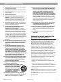
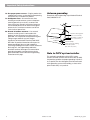
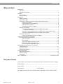
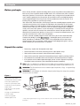
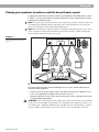
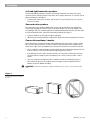
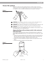
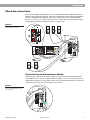
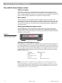
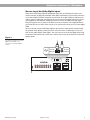
The Bose® Acoustimass® 15 Home Theater Speaker
System
Owner’s Guide
October 22, 2001
AM194452_06_V.pdf
Introduction
Thank you
We appreciate your choice of the Bose® Acoustimass® 15 home theater speaker system. With
these Virtually Invisible® speakers you will surround yourself with realistic sound, with a
minimal amount of equipment. Your system features new third generation Acoustimass cube
speaker arrays, a product of the continuous research and development at Bose Corporation.
These cube speakers deliver more lifelike sound and better overall performance, yet are
smaller than their predecessors.
Your speaker system is completely compatible with the most modern home theater receivers
and program material. Bose proprietary Integrated Signal Processing and dedicated bass
amplification assure hi-fidelity and bass for all channels regardless of your home theater
receiver’s settings.
Important Information
WARNING: To reduce the risk of fire or electric shock, do not expose the Powered Acoustimass module to rain or moisture.
CAUTION: To prevent electric shock, match wide blade of plug to wide slot, insert fully.
CAUTION
RISK OF ELECTRICAL SHOCK
DO NOT OPEN
CAUTION: TO REDUCE THE RISK OF ELECTRIC SHOCK,
DO NOT REMOVE COVER (OR BACK).
NO USER-SERVICEABLE PARTS INSIDE.
REFER SERVICING TO QUALIFIED PERSONNEL.
These CAUTION marks are located on the Acoustimass module:
The lightning flash with arrowhead symbol, within an equilateral triangle, is intended to alert the
user to the presence of uninsulated dangerous voltage within the system enclosure that may
be of sufficient magnitude to constitute a risk of electric shock.
The exclamation point within an equilateral triangle, as marked on the system, is intended to
alert the user to the presence of important operating and maintenance instructions in this
owner’s guide.
Additional safety information
See the additional instructions on the Important Safety Information page enclosed with this
owner’s guide.
Please read this owner’s guide
Please take the time to follow this owner’s guide carefully. It will help you set up and operate
your system properly, and enjoy all of its advanced features. Save your owner’s guide for
future reference.
2
October 22, 2001
AM194452_06_V.pdf
Important Safety Instructions
1. Read these instructions – for all components
before using this product.
2. Keep these instructions – for future reference.
3. Heed all warnings – on the product and in the
owner’s guide.
4. Follow all instructions.
5. Do not use this apparatus near water or
moisture – Do not use this product near a
bathtub, washbowl, kitchen sink, laundry tub, in a
wet basement, near a swimming pool, or anywhere else that water or moisture are present.
6. Clean only with a dry cloth – and as directed
by Bose® Corporation. Unplug this product from
the wall outlet before cleaning.
7. Do not block any ventilation openings.
Install in accordance with the
manufacturer’s instructions – To ensure
reliable operation of the product and to protect it
from overheating, put the product in a position
and location that will not interfere with its proper
ventilation. For example, do not place the product
on a bed, sofa, or similar surface that may block
the ventilation openings. Do not put it in a built-in
system, such as a bookcase or a cabinet that may
keep air from flowing through its ventilation
openings.
8. Do not install near any heat sources, such
as radiators, heat registers, stoves or other
apparatus (including amplifiers) that produce heat.
9. Do not defeat the safety purpose of the
polarized or grounding-type plug. A polarized plug has two blades with one wider
than the other. A grounding-type plug has
two blades and a third grounding prong. The
wider blade or third prong are provided for
your safety. If the provided plug does not fit
in your outlet, consult an electrician for
replacement of the obsolete outlet.
10. Protect the power cord from being walked
on or pinched, particularly at plugs, convenience receptacles, and the point where
they exit from the apparatus.
11. Only use attachments/accessories specified by the manufacturer.
12. Use only with the cart, stand, tripod,
bracket or table specified by the
manufacturer or sold with the
apparatus. When a cart is used,
use caution when moving the
cart/apparatus combination to
avoid injury from tip-over.
13. Unplug this apparatus during lightning
storms or when unused for long periods of
time – to prevent damage to this product.
AM251174_03_V.pdf
14. Refer all servicing to qualified service personnel. Servicing is required when the apparatus
has been damaged in any way: such as powersupply cord or plug is damaged; liquid has
been spilled or objects have fallen into the
apparatus; the apparatus has been exposed to
rain or moisture, does not operate normally, or
has been dropped – Do not attempt to service this
product yourself. Opening or removing covers may
expose you to dangerous voltages or other hazards.
Please call Bose to be referred to an authorized
service center near you.
15. To prevent risk of fire or electric shock, avoid
overloading wall outlets, extension cords, or
integral convenience receptacles.
16. Do not let objects or liquids enter the product –
as they may touch dangerous voltage points or
short-out parts that could result in a fire or electric
shock.
17. See product enclosure for safety related
markings.
Information about products that
generate electrical noise
If applicable, this equipment has been tested and found
to comply with the limits for a Class B digital device,
pursuant to Part 15 of the FCC rules. These limits are
designed to provide reasonable protection against
harmful interference in a residential installation. This
equipment generates, uses, and can radiate radio
frequency energy and, if not installed and used in accordance with the instructions, may cause harmful interference to radio communications. However, this is no
guarantee that interference will not occur in a particular
installation. If this equipment does cause harmful interference to radio or television reception, which can be
determined by turning the equipment off and on, you are
encouraged to try to correct the interference by one or
more of the following measures:
• Reorient or relocate the receiving antenna.
• Increase the separation between the equipment and
receiver.
• Connect the equipment to an outlet on a different
circuit than the one to which the receiver is connected.
• Consult the dealer or an experienced radio/TV technician for help.
Note: Unauthorized modification of the receiver or radio
remote control could void the user’s authority to operate
this equipment.
This product complies with the Canadian ICES-003 Class
B specifications.
October 22, 2001
a
English
Important Safety Instructions
18. Use proper power sources – Plug the product into
a proper power source, as described in the operating
instructions or as marked on the product.
19. Avoid power lines – Use extreme care when
installing an outside antenna system to keep from
touching power lines or circuits, as contact with
them may be fatal. Do not install external antennas
near overhead power lines or other electric light or
power circuits, nor where an antenna can fall into
such circuits or power lines.
20. Ground all outdoor antennas – If an external
antenna or cable system is connected to this
product, be sure the antenna or cable system is
grounded. This will provide some protection against
voltage surges and built-up static charges.
Section 810 of the National Electrical Code ANSI/
NFPA No. 70 provides information with respect to
proper grounding of the mast and supporting
structure, grounding of the lead-in wire to an antenna
discharge unit, size of grounding conductors,
location of antenna-discharge unit, connection to
grounding electrodes, and requirements for the
ground electrode. Refer to the antenna grounding
illustration on this page.
Antenna grounding
Example of antenna grounding as per National Electrical
Code, ANSI/NFPA 70.
Antenna lead in wire
Ground clamp
Antenna discharge unit
(NEC Section 810-20)
Grounding conductors
Electric service
equipment
(NEC Section 810-21)
Ground clamps
Power service grounding
electrode system
(NEC ART 250, Part H)
Note to CATV system installer
This reminder is provided to call the CATV system
installer’s attention to Article 820-40 of the NEC (of USA)
that provides guidelines for proper grounding. In particular, it specifies that the cable ground shall be connected
to the grounding system of the building, as close to the
point of cable entry as is practical.
b
October 22, 2001
AM251174_03_V.pdf
Contents
Where to find...
Español
Introduction
Thank you ..................................................................................................................... 2
Important Information ................................................................................................... 2
Contents
Where to find ................................................................................................................ 3
For your records ........................................................................................................... 3
Setting Up
Before you begin ........................................................................................................... 4
Unpack the carton ........................................................................................................ 4
Placing your speakers to achieve realistic home theater sound .................................. 5
Center cube speaker ........................................................................................... 5
Left and right front cube speakers ...................................................................... 6
Surround cube speakers ..................................................................................... 6
Powered Acoustimass® module .......................................................................... 6
Connect the speakers ................................................................................................... 7
Connect the Powered Acoustimass module to the center
and front cube arrays ................................................................................... 7
Connect the Powered Acoustimass module to the surround cube arrays ......... 8
Connect the Powered Acoustimass module to the receiver ............................... 8
Check the connections ................................................................................................. 9
Plug in the Powered Acoustimass Module ......................................................... 9
Using Your Acoustimass 15 speakers
For realistic home theater sound ................................................................................ 10
LFE level control ................................................................................................ 10
Bass control ...................................................................................................... 10
Setting your Dolby Pro-Logic receiver .............................................................. 10
Setting your Dolby Digital receiver .................................................................... 10
Be sure to get the Dolby Digital signal .............................................................. 11
Maintaining Your Acoustimass 15 speakers
Troubleshooting .......................................................................................................... 12
Customer service ........................................................................................................ 12
Cleaning the speakers ................................................................................................ 12
Product Information
Technical information .................................................................................................. 13
Warranty period .......................................................................................................... 13
Accessories ................................................................................................................. 13
Bose® Corporation .................................................................................... inside back cover
Français
For your records
Serial numbers are located on the connection panel of the Powered Acoustimass module.
Serial number: _________________________________________________________________
Dealer name: __________________________________________________________________
Dealer phone: _______________________ Purchase date: ___________________________
We suggest you keep your sales slip and warranty card together with this owner’s guide.
AM194452_06_V.pdf
October 22, 2001
3
Setting Up
Before you begin
Bose® Virtually Invisible® speaker technology allows you to enjoy lifelike home performances
from the very latest surround-sound encoded movies, CDs, and television shows, without a
room full of speakers. Each of the five cube speaker arrays, along with the Powered Acoustimass® module, reproduces the full-spectrum of sound from multi-channel digital programming. Integrated Signal Processing assures full bass performance from all channels, at all
listening levels, regardless of your receiver settings.
Your stereo VCR, stereo television, or DVD player sends the encoded program material to the
surround-sound receiver, which interprets and distributes the information to the Powered
Acoustimass module. The module delivers the bass for all channels and sends appropriate
sounds to each cube array. The sound mix varies with different program types: dialogue is
usually sent to the center speaker, a visual soundstage is created by the left and right front
speakers, and you feel in the center of the action because sounds and special effects are
directed to the surround (rear) speakers. At any point in a surround-sound performance, you
may hear sound from one, a few, or all of the speakers.
To select surround-encoded program material, look for any of the terms Surround, Dolby
Surround, the double-D symbol
*, other digital formats, or the word “surround” preceding a TV broadcast. Your system is fully compatible with the latest home
theater receivers. You can also enjoy a wide variety of stereo programming that is not surround-encoded with your Acoustimass 15 speakers.
Unpack the carton
• Remove any staples from the opened carton flaps.
• Remove the brown inner carton containing the five cube speaker arrays.
• Gently roll the carton over onto its side and then onto its opening.
• Slowly lift the carton from around the Powered Acoustimass module’s packing cushions.
• Do not detach the removable cables connected to the Powered Acoustimass module.
• If the speakers or the module appear damaged, do not use them. Repack everything in
the original carton and contact your authorized Bose dealer immediately.
Note: Now is a good time to record the serial number of these speakers on page 2 of this
guide and on your warranty card. Please save all packing materials for possible future use.
WARNING: The Powered Acoustimass module weighs 33 pounds (15 kg). Use good lifting
practice to avoid injury.
WARNING: To avoid danger of suffocation, keep the plastic bags that wrap these speakers
out of the reach of children.
Figure 1
USA
What comes in the carton:
• Powered Acoustimass module
• Five cube speaker arrays
Europe
• 20' (6 m) system input cable
• Three 20' (6 m) front speaker
output cables
UK/Singapore
• Two 50' (15 m) rear speaker
output cables
• 4 large, 4 small rubber feet
Australia
• Owner’s Guide
• Quick set up guide
• Module power cord
* Dolby, Dolby Digital, Dolby Pro-Logic, and the double-D symbol are trademarks of Dolby Laboratories Licensing
Corporation.
4
October 22, 2001
AM194452_06_V.pdf
Setting Up
Placing your speakers to achieve realistic home theater sound
A suggested home theater layout that conforms to the guidelines described above is shown
in Figure 2. You may want to place the speakers differently, to take advantage of the sound
characteristics of different rooms.
Note: The cube arrays are identical and can be used for any channel. All of the cube arrays
are magnetically shielded to prevent interference with a television picture. Twist the cube
arrays so the speakers create room-filling sound patterns.
Note: Bose wall brackets and floor stands can extend your placement options. See “Accessories” on page 13. Please follow wall bracket instructions carefully. Proper mounting will
insure optimum performance from your system.
Figure 2
One suggested home theater
layout
Center cube speaker
The center speaker localizes action and dialogue on your screen. Sound should seem to
come from within the picture.
• Place the center cube array above, below, or on top of your television. If below, be sure
that it is not supporting the weight of the television in any way.
• Keep the cube array as close to the vertical center of the screen as possible, for the most
accurate dialogue reproduction.
CAUTION: If you are placing the center cube array on top of the television, use the smaller
of the two sets of four rubber feet provided. This will provide extra stability on surfaces such
as marble or glass. Additional rubber feet are available, free, by calling the Bose® customer
service numbers inside the back cover of this manual. Ask for Part Number 178321-04.
AM194452_06_V.pdf
October 22, 2001
5
Setting Up
Left and right front cube speakers
The left and right front speakers create a sound image wider than the screen that seems
natural to viewers sitting anywhere in the room. You can place them near a TV screen with no
picture interference. See figure 2.
• Place the front cube arrays on either side of your TV, at least 6 feet (2 m), or as much as
15 feet (5 m) apart.
Surround cube speakers
The surround, or rear, speakers add discrete sounds and special effects that expand the
visual image, bringing the viewer into the center of the action. The surround speakers may
carry dialog as well. The surround speakers should be positioned to allow the sound to reach
the viewer from both sides, rather than from directly behind. See Figure 2.
• Place the speakers at ear height or higher, if possible
• Adjust the rear surround speakers to direct the sound to the front and back of the listener.
Powered Acoustimass® module
Bose® Acoustimass speaker technology takes advantage of the fact that the source of pure
bass sound is difficult to locate, so you can hide the Powered Acoustimass module conveniently out of sight. Place the module at the same end of the room as the television monitor.
• You may hide the module behind or under furniture, but do not block the opening. Be sure
there is at least 2 inches (5 cm) between the opening and any surface.
• If the opening faces the wall it increases the bass; if it faces away it decreases the bass.
For the most bass response, place the opening 2 to 3 inches (5 to 8 cm) from a wall or
corner.
• You may stand the Powered Acoustimass module vertically or horizontally (Figure 3).
• After selecting a place for the module, attach the larger set of four rubber feet to the
bottom surface for additional stability.
CAUTION: To prevent interference, keep the module at least 2 feet (.6 m) from the television.
Figure 3
Powered Acoustimass module
positions
6
October 22, 2001
AM194452_06_V.pdf
Setting Up
Connect the speakers
Connect the cube arrays to the Powered Acoustimass® module, and then connect the
module to your receiver. The supplied cables make this easy. The cables may be separated
or “unzipped” as much as needed to comfortably reach the speakers. See Figure 4.
Figure 4
Separating cables
CAUTION: Before making any connections turn off your receiver and unplug it from the
outlet (AC power mains). Not doing so may result in damage to your system.
CAUTION: Never connect the cubes directly to a receiver output. Always connect the cube
arrays to the Powered Acoustimass module, then connect the module to the receiver.
CAUTION: Never use broken or frayed wiring, which can result in electrical shock or
damage to your system. The supplied cables are not intended for in-wall installation. Check
local building codes or enlist a qualified installer.
Connect the Powered Acoustimass module to the center and
front cube arrays
Three individual 20 (6m) foot wire pairs connect the Powered Acoustimass module to the
Center, Right, and Left front cube arrays. Each cable connects to the module with a single
plug.
1. Connect the wire pair marked C to the center speaker. Just press the terminal tab on the
back of the cube array to insert the marked wire into the red terminal and the plain wire
into the black terminal. See Figure 5. Release the tab to secure the wires.
2. Connect the wire pair marked R to the right front speaker (to the right of the TV as you
face it).
3. Connect the wire pair marked L to the left front speaker.
Figure 5
Making cube speaker connections
Marked wire
to Red terminal
AM194452_06_V.pdf
October 22, 2001
7
Setting Up
Connect the Powered Acoustimass® module to the surround
cube arrays
The 50 foot (15 m) cable with two pairs of wires connects the Powered Acoustimass module
to the Right and Left surround cube arrays. Each has an individual plug on the module end.
1. The wire marked R connects the module to the right surround speaker (on your right as
you face the TV). As shown in Figure 5, press the terminal tab on the back of cube array to
insert the marked wire into the red terminal and the plain wire into the black terminal.
2. The wire marked L connects the module to the left surround speaker.
3. Insert the connectors firmly into their jacks at the Powered Acoustimass module.
Connect the Powered Acoustimass module to the receiver
The 20 foot (6m) cable with five pairs of wires and a single wire with an RCA plug connects
the module to the outputs on the receiver as shown in the table below.
Note: The RCA plug comes with a cover installed. Remove this cover for connection to the
LFE/SUBWOOFER OUT jack. If your receiver has no LFE/SUBWOOFER OUT jack, leave the
plug cover in place; in this case this wire will not be used.
• Match the polarity on the receiver. Connect the wire pairs in phase (+ to + and – to –).
a. Attach each marked wire (+) to the appropriate + terminal.
b. Attach each plain wire (–) to the appropriate – terminal.
• Connect the RCA plug to the receiver’s LFE/SUBWOOFER OUT jack.
• At the Powered Acoustimass module, be sure the receiver cable connector is firmly
inserted.
WIRE
RECEIVER CONNECTION
CENTER
CENTER (MAIN, A)
RIGHT
RIGHT FRONT (MAIN, A)
LEFT
LEFT FRONT (MAIN, A)
RIGHT SURROUND
RIGHT SURROUND (REAR)
LEFT SURROUND
LEFT SURROUND (REAR)
LFE RCA PLUG
LFE SUBWOOFER OUT
CAUTION: Do not connect the Powered Acoustimass module directly to your television
unless the television provides surround decoding circuitry and amplified outputs for all
channels.
CAUTION: Do not allow exposed wires to brush against each other; this could damage
your receiver.
8
October 22, 2001
AM194452_06_V.pdf
Setting Up
Check the connections
Check all connections from the receiver to the Powered Acoustimass module and from the
module to the cube arrays (Figure 6). Make sure all cube arrays are connected to the proper
terminals according to their position in your room. Check that all wires are connected in
phase (+ to + and – to –). Incorrect wiring can result in a total loss of module output. Correct
wiring problems before you plug your receiver in and turn it on.
Figure 6
Completed connections
FRONT SPEAKE
R
3+
HT
RIG
+3
FRONT SPEAKERS
R
L
SURROUND SPEAKERS
R REAR L CENTER
LFE/SUBWOOFER
OUT
Plug in the Powered Acoustimass Module
When you have checked all connections, plug in the power cord of the Powered Acoustimass module. Be sure to turn the power switch on (Figure 7). It is not necessary to turn the
module off after each use. The speaker system turns on and off automatically as it receives a
signal from the receiver. Turn the system off at the receiver.
Figure 7
Turn on the Powered Acoustimass module
AM194452_06_V.pdf
October 22, 2001
9
Using Your Acoustimass® 15 Speakers
For realistic home theater sound
LFE level control
The LFE level control on your Powered Acoustimass module increases or decreases the
relative level of low frequency effects on movie soundtracks. Use it to regulate the presence
of these underlying deep bass sounds. You may find it unnecessary to adjust this control. The
factory, or detent setting is appropriate for a majority of listening situations.
Bass control
The Bass control on your Powered Acoustimass module can help you customize your
listening room. Turning the control to the right will add bass to the sound in rooms that might
be characterized as too shrill. Turning down the control will “brighten” the listening room. As
with the LFE level control, you may find the factory setting to be completely appropriate for
your listening room.
Setting your Dolby Pro-Logic receiver
For video applications, we recommend the surround-sound center mode setting of your
receiver as WIDE (Figure 8). Instructions for this process vary, depending on the brand and
model of receiver you are using. Follow your receiver owner’s guide for testing and adjusting
the balance of each speaker.
Figure 8
A Dolby Pro-Logic receiver with
the center mode set to WIDE
Setting your Dolby Digital receiver
Your Acoustimass 15 speakers are fully compatible with the output from Dolby Digital receivers. Integrated Signal Processing assures full bass reproduction for all channels regardless of
receiver settings. However, the table below suggests a set of recommended receiver settings.
The cube speakers are full-range, or LARGE speakers on the Digital screen menu. Turn the
subwoofer and the LFE (low frequency effects) ON. Set the crossover to the lowest number
possible, typically 80 Hz.
Speaker
Left and Right Front
Center
Left and Right Surround
Subwoofer
LFE (low frequency effects)
Setting at receiver
Large
Large
Large
ON
ON (at maximum setting)
Note: The Acoustimass 15 speaker system incorporates an automatic protection circuit,
which guards against most kinds of damage from electrical stress or overload. This circuit
activates at high volume levels to reduce output, causing a slight decrease in volume. This is
normal operation and indicates that power input may be exceeding safe levels. Sustained
listening at these levels is not recommended.
10
October 22, 2001
AM194452_06_V.pdf
Using Your Acoustimass® 15 Speakers
Be sure to get the Dolby Digital signal
To be sure that the Dolby Digital or other digital signal from your DVD player reaches your
receiver, connect its digital sound output to the digital sound input on your receiver. You must
use a coaxial cable, with RCA connectors on each end, or an optical (Toslink) cable that has
unique, “square” cable ends. See Figure 9. Be sure to connect the digital sound jacks; these
are in addition to the traditional analog connections that carry the Dolby Pro-Logic signal.
Many DVD players have a switch on the back which you must place in the digital position. If
you cannot find such a switch, there may be an on screen menu where you must select digital
audio.
You must also be sure to select Dolby Digital at your receiver’s front panel or remote control.
For example, when playing a movie on a DVD, you must select a video output, in this case
DVD, and an audio output, Dolby Digital. You may also have to set up the digital signal using
the receiver’s front panel or on-screen menu. Please consult your receiver owner’s manual for
specific details.
Figure 9
Use either the optical or coaxial
digital sound cables and
connections for Dolby Digital
sound.
AC-3
PLAY IN
DIGITAL (OPTICAL)
IN
AC-3
PLAY IN
DIGITAL (OPTICAL)
IN
FRONT SPEAKERS
R
L
AM194452_06_V.pdf
October 22, 2001
PLAY IN
(COAXIAL)
PLAY IN
(COAXIAL)
SURROUND SPEAKERS
R REAR L CENTER
11
Maintaining Your Acoustimass® 15 Speakers
Troubleshooting
If you have a problem with your Acoustimass 15 speakers, turn off your sound source and try
the solutions below. If you still have a problem, contact your Bose® dealer to arrange for
service. To contact Bose directly, refer to the inside back cover of this guide.
Problem
What to do
System does not function at all
•
•
No sound
•
•
•
Make sure the receiver and Powered Acoustimass module are plugged
into an operating AC wall outlet and that the units are turned on.
Be sure to select a source at the receiver (video, CD, DVD, tuner).
•
•
Check the speaker connections.
Turn the Powered Acoustimass module ON.
For digital sound, be sure a coaxial or optical cable connects the digital
output of the DVD player with the digital input on your receiver.
Be sure the audio source selected is correct. For example: select DVD
audio on your receiver and player for DVD sound.
Disconnect any headphones.
Increase the volume.
No sound from cube arrays
•
Be sure the Powered Acoustimass module is plugged in and turned on.
Sound is distorted
•
•
Make sure speaker wire is not damaged.
Reduce the volume of external components connected to the receiver.
No bass
•
Make sure the speaker connections at the receiver or amplifier are correct
(+ to + and – to –).
Not enough or too much bass
•
Move the Powered Acoustimass module closer to a wall or corner to
increase bass. Move it farther away from a wall or corner to decrease bass.
Adjust the LFE level control.
•
•
No surround-sound
•
Be sure your receiver is processing a signal from a Hi-Fi VCR, stereo TV,
laserdisc, or DVD player, or other surround-sound source. If you are using
the Dolby Pro-Logic mode, check that surround-sound is turned ON. If
you are using Digital programming, verify that the settings are correct at the
receiver. Be sure the source material (DVD, laser disc, or broadcast programming) is Dolby Digital encoded.
Customer service
For additional help in solving problems, contact Bose customer service. See the inside back
cover for Bose customer service offices and phone numbers.
Cleaning the speakers
The cabinets of your Acoustimass 15 speaker system may be cleaned with a soft damp cloth.
Do not use any sprays near the system or allow liquids to spill into any openings. Also, do not
use any solvents, chemicals, or cleaning solutions containing alcohol, ammonia, or abrasives.
The grille assemblies on the cube arrays may be carefully vacuumed, if necessary. Please
note that the drivers are located directly behind the grille cloth, and are easily damaged if
reasonable care is not taken.
12
October 22, 2001
AM194452_06_V.pdf
Product Information
Technical information
Powered Acoustimass® module power rating
USA/Canada: 120V ~ 50/60 Hz 260W
Europe/Australia: 220-240V ~ 50/60 Hz 260W
Features
• Direct/Reflecting® speaker technology
• Virtually Invisible® speaker design
• Acoustimass speaker technology combined with Integrated Signal Processing
• Magnetically shielded cube speaker arrays
• Automatic system protection circuitry
• Syncom® computer quality control
Speaker driver complement
Cube speaker arrays: two 2.50-inch (6.35 cm) TwiddlerTM speakers
Powered Acoustimass module: two 5.50-inch (14 cm) woofers
Connectivity
Compatible with A/V receivers and amplifiers rated from 10 to 200 watts per channel,
rated from 4 to 8 ohms
Finish
Cube arrays: Black or Arctic White finish
Powered Acoustimass module: Scratch-resistant Black or Arctic White textured finish
Size/Weight
Cube speaker arrays: 6.2"H x 3.1"W x 4.0"D (15.7 cm x 7.8 cm x 10.2 cm)
2.4 lb (1.1 kg)
Powered Acoustimass module: 14.0"H x 23.3"W x 7.5"D (35.5 cm x 19.0 cm x 59.0 cm)
33 lb (15 kg)
Packed system: 53 lb (24 kg)
Warranty period
Bose® Acoustimass 15 speakers are covered by a limited five-year transferable warranty. The
built-in amplifier and electronic components are covered by a limited one-year warranty.
Details of the warranty are provided on the warranty card that came with your system. Please
fill out the information section on the card and mail it to Bose.
Accessories
Floor stands: UFS-20B (black), UFS-20W (white)
Wall brackets: UB-20B (black), UB-20W (white)
Module input cable adapter for use with existing wiring:
PN194460-001 (black),
PN194460-002 (white)
Module input 20 foot (6.1 m) extension cable: PN198221-001 (black), PN198221-002 (white)
AM194452_06_V.pdf
October 22, 2001
13
1
Bose® Corporation
USA
Bose Corporation, The Mountain
Framingham, MA 01701-9168
1-800-367-4008
Phone hours - ET (eastern time):
Weekdays 8:30 a.m. to 8 p.m.
Saturdays 9 a.m. to 3 p.m.
Canada
Bose Ltd., 1-35 East Beaver Creek Road
Richmond Hill, Ontario L4B 1B3
1-800-465-2673
Phone hours - ET (eastern time):
Weekdays 9 a.m. to 5 p.m.
European Office
Bose Products B.V., Nijverheidstraat 8
1135 GE Edam, Nederland
TEL 0299-390111
FAX 0299-390114
Australia
Bose Pty Limited, 1 Sorrell Street
Parramatta, NSW, 2150
TEL 02 9204-6111
FAX 02 9204-6122
Belgique/België
Bose N.V., Limesweg 2, B-3700 Tongeren
TEL 012-390800
FAX 012-390840
Danmark
Bose A/S, Industrivej 7, 2605 Brøndby
TEL 4343-7777
FAX 4343-7818
Deutschland
Bose GmbH, Max-Planck-Straße 36d
D-61381 Friedrichsdorf
TEL 06172-71040
FAX 06172-710419
France
Bose S.A., 6, rue Saint Vincent
78100 Saint Germain en Laye
TEL 01-30616363
FAX 01-30614105
India
Bose Corporation India Private Limited
W-16, Greater Kailash-II
New Delhi 110 048
TEL (011) 648 4462 FAX (011) 648 4463
Ireland
Bose Corporation
Carrickmacross, Co Monaghan
TEL (042) 9661988
FAX (042) 9661998
Italia
Bose S.p.A., Via della Magliana 876
00148 Roma
www.bose.iT
TEL 06-65670802
FAX 06-65680167
Japan
Bose K.K., Shibuya YT Building
28-3 Maruyama-cho
Shibuya-ku, Tokyo 150
TEL 3-5489-0955
FAX 3-5489-0592
Nederland
Bose B.V., Nijverheidstraat 8
1135 GE Edam
TEL 0299-390111
FAX 0299-390109
Norge
Bose A/S, Solheimsgate 11
N-2001, Lillestrøm
TEL 63-817380
FAX 63-810819
Österreich
Bose Ges.m.b.H., Vienna Business Park
Wienerbergstrasse 7 (10.OG)
A-1100 Vienna
TEL 01-60404340
FAX 01-604043423
Schweiz
Bose AG, Rünenbergerstrasse 13
4460-Gelterkinden
TEL 061-9815544
FAX 061-9815502
Sverige
Bose A/S, Johannefredsgatan 4
S-43153 Mölndal
TEL 31-878850
FAX 31-274891
United Kingdom
Bose Limited
1 Ambley Green
Gillingham Business Park
Gillingham, Kent ME8 ONJ
TEL 0870-741-4500 FAX 0870-741-4545
From other locations
Bose Customer Service, 1 New York Ave.
Framingham, MA 01701-9168 USA
TEL (508) 766-1900 FAX (508) 766-1919
World Wide Web
www.bose.com
© 2000 Bose Corporation, The Mountain,
Framingham, MA 01701-9168 USA
194452 AM Rev. 06 JN98831