1
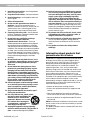
The Bose® Acoustimass® 10 Series II Home Theater
Speaker System
Owner’s Guide
October 22, 2001
AM194646_02 _V.pdf
English
Introduction
Thank you
We appreciate your choice of the Bose® Acoustimass® 10 Series II home theater speaker
system. With these Virtually Invisible® speakers you’ll surround yourself with realistic sound,
without a lot of equipment. Your system features new third generation Acoustimass cube
speaker arrays, a product of the continuous research and development at Bose Corporation.
These cube speakers deliver more lifelike sound and better overall performance, yet are
smaller than their predecessors.
Important information
Please read this owner’s guide
The set-up and operation of your Acoustimass 10 Series II speaker system is significantly
different from other speakers. Please take the time to read this owner’s guide carefully. It will
help you set up and operate your system properly, and enjoy all of its advanced features.
Save your owner’s guide for future reference.
Declaration
of Conformity
We, the offerer:
Bose® Corporation, The Mountain,
Framingham, MA 01701-9168 USA
acknowledge our sole responsibility, that the product:
Kind of equipment:
Type designation:
Loudspeakers
Acoustimass® 10 Series II
Home Theater Speakers
in accordance with EMC Directive 89/336/EEC and Article 10(1) of the Directive,
is in compliance with the following norm(s) or document(s):
Technical regulations:
EN50081-1, EN50082-1
Accredited by Bose Corporation
1 May 1998
Bose B.V., Nijverheidstraat 8
1135 GE Edam, The Netherlands
2
October 22, 2001
Anton Schalkamp
General Manager, Bose Europe
Manufacturer’s authorized EU representative
AM19464_02_V.pdf
Important Safety Instructions
1. Read these instructions – for all components
before using this product.
2. Keep these instructions – for future reference.
3. Heed all warnings – on the product and in the
owner’s guide.
4. Follow all instructions.
5. Do not use this apparatus near water or
moisture – Do not use this product near a
bathtub, washbowl, kitchen sink, laundry tub, in a
wet basement, near a swimming pool, or anywhere else that water or moisture are present.
6. Clean only with a dry cloth – and as directed
by Bose® Corporation. Unplug this product from
the wall outlet before cleaning.
7. Do not block any ventilation openings.
Install in accordance with the
manufacturer’s instructions – To ensure
reliable operation of the product and to protect it
from overheating, put the product in a position
and location that will not interfere with its proper
ventilation. For example, do not place the product
on a bed, sofa, or similar surface that may block
the ventilation openings. Do not put it in a built-in
system, such as a bookcase or a cabinet that may
keep air from flowing through its ventilation
openings.
8. Do not install near any heat sources, such
as radiators, heat registers, stoves or other
apparatus (including amplifiers) that produce heat.
9. Do not defeat the safety purpose of the
polarized or grounding-type plug. A polarized plug has two blades with one wider
than the other. A grounding-type plug has
two blades and a third grounding prong. The
wider blade or third prong are provided for
your safety. If the provided plug does not fit
in your outlet, consult an electrician for
replacement of the obsolete outlet.
10. Protect the power cord from being walked
on or pinched, particularly at plugs, convenience receptacles, and the point where
they exit from the apparatus.
11. Only use attachments/accessories specified by the manufacturer.
12. Use only with the cart, stand, tripod,
bracket or table specified by the
manufacturer or sold with the
apparatus. When a cart is used,
use caution when moving the
cart/apparatus combination to
avoid injury from tip-over.
13. Unplug this apparatus during lightning
storms or when unused for long periods of
time – to prevent damage to this product.
AM194646_02_V.pdf
14. Refer all servicing to qualified service personnel. Servicing is required when the apparatus
has been damaged in any way: such as powersupply cord or plug is damaged; liquid has
been spilled or objects have fallen into the
apparatus; the apparatus has been exposed to
rain or moisture, does not operate normally, or
has been dropped – Do not attempt to service this
product yourself. Opening or removing covers may
expose you to dangerous voltages or other hazards.
Please call Bose to be referred to an authorized
service center near you.
15. To prevent risk of fire or electric shock, avoid
overloading wall outlets, extension cords, or
integral convenience receptacles.
16. Do not let objects or liquids enter the product –
as they may touch dangerous voltage points or
short-out parts that could result in a fire or electric
shock.
17. See product enclosure for safety related
markings.
Information about products that
generate electrical noise
If applicable, this equipment has been tested and found
to comply with the limits for a Class B digital device,
pursuant to Part 15 of the FCC rules. These limits are
designed to provide reasonable protection against
harmful interference in a residential installation. This
equipment generates, uses, and can radiate radio
frequency energy and, if not installed and used in accordance with the instructions, may cause harmful interference to radio communications. However, this is no
guarantee that interference will not occur in a particular
installation. If this equipment does cause harmful interference to radio or television reception, which can be
determined by turning the equipment off and on, you are
encouraged to try to correct the interference by one or
more of the following measures:
• Reorient or relocate the receiving antenna.
• Increase the separation between the equipment and
receiver.
• Connect the equipment to an outlet on a different
circuit than the one to which the receiver is connected.
• Consult the dealer or an experienced radio/TV technician for help.
Note: Unauthorized modification of the receiver or radio
remote control could void the user’s authority to operate
this equipment.
This product complies with the Canadian ICES-003 Class
B specifications.
October 22, 2001
a
English
Important Safety Instructions
18. Use proper power sources – Plug the product into
a proper power source, as described in the operating
instructions or as marked on the product.
19. Avoid power lines – Use extreme care when
installing an outside antenna system to keep from
touching power lines or circuits, as contact with
them may be fatal. Do not install external antennas
near overhead power lines or other electric light or
power circuits, nor where an antenna can fall into
such circuits or power lines.
20. Ground all outdoor antennas – If an external
antenna or cable system is connected to this
product, be sure the antenna or cable system is
grounded. This will provide some protection against
voltage surges and built-up static charges.
Section 810 of the National Electrical Code ANSI/
NFPA No. 70 provides information with respect to
proper grounding of the mast and supporting
structure, grounding of the lead-in wire to an antenna
discharge unit, size of grounding conductors,
location of antenna-discharge unit, connection to
grounding electrodes, and requirements for the
ground electrode. Refer to the antenna grounding
illustration on this page.
Antenna grounding
Example of antenna grounding as per National Electrical
Code, ANSI/NFPA 70.
Antenna lead in wire
Ground clamp
Antenna discharge unit
(NEC Section 810-20)
Grounding conductors
Electric service
equipment
(NEC Section 810-21)
Ground clamps
Power service grounding
electrode system
(NEC ART 250, Part H)
Note to CATV system installer
This reminder is provided to call the CATV system
installer’s attention to Article 820-40 of the NEC (of USA)
that provides guidelines for proper grounding. In particular, it specifies that the cable ground shall be connected
to the grounding system of the building, as close to the
point of cable entry as is practical.
©2001 Bose Corporation,
The Mountain, Framingham, MA
01701-9168 USA
255805 AM Rev.00 JN10494
b
October 22, 2001
AM19464_02_V.pdf
Contents
Introduction
Thank you ..................................................................................................................... 2
Important Information ................................................................................................... 2
Using Your Acoustimass 10 Series II speaker system
For realistic home theater sound ................................................................................ 13
Deutsch
Setting Up
Before you begin ........................................................................................................... 4
Unpacking the carton ................................................................................................... 4
Placing your Acoustimass® 10 Series II speakers to achieve
realistic home theater sound .................................................................................. 5
Selecting the locations for your speakers ..................................................................... 6
Connecting the speakers .............................................................................................. 9
Dansk
Contents
Where to find… ............................................................................................................. 3
For your records ........................................................................................................... 3
English
Where to find...
Maintaining Your Acoustimass 10 Series II speaker system
Troubleshooting .......................................................................................................... 14
Customer service ........................................................................................................ 14
Cleaning the speakers ................................................................................................ 15
Warranty period .......................................................................................................... 15
Accessories ................................................................................................................. 15
Bose® Corporation .................................................................................... inside back cover
For your records
The serial number is located near the connection panel on the Acoustimass module.
Serial number: _________________________________________________________________
Dealer name: __________________________________________________________________
Dealer phone: _______________________ Purchase date: ___________________________
We suggest you keep your sales slip and warranty card together with this owner’s guide.
AM194646_02_V.pdf
October 22, 2001
3
Français
Product Information
Technical information .................................................................................................. 16
English
Setting Up
Before you begin
Bose® Virtually Invisible® speaker technology allows you to enjoy lifelike home performances
from the very latest surround-sound encoded movies, CDs, and television shows, without a
room full of speakers.
Your stereo VCR or stereo television sends the encoded program material to the surroundsound receiver, which interprets it by distributing various sounds to particular speakers.
Although the sound mix varies with different types of programs, dialogue is usually sent to
the center speaker while sounds from the left or right side of the picture go to the left or right
front speakers. Ambient sounds and special effects are directed to one or both of the surround (rear) speakers. The unique, easy-to-hide Acoustimass® module delivers bass for all
channels. At any point in surround-sound performance, you may hear sound from all or just a
few of the speakers.
To select surround-encoded program material, look for any of the terms Surround, Dolby
Surround, and the double-D symbol
* on tapes and discs, and the word
“surround” preceding a TV broadcast. Your Acoustimass 10 Series II home theater speakers
are also compatible with Dolby Digital* (also known as AC-3) receivers and program material.
The special settings for Dolby Pro-Logic and Dolby Digital receivers are described on
page 13.
You can also enjoy a wide variety of stereo programming that is not surround-encoded with
your Acoustimass 10 Series II speakers. Simply adjust your receiver accordingly.
Unpacking the carton
• Remove any staples from the opened carton flaps.
• Remove the brown inner cartons containing the five cube speaker arrays and the Acoustimass module terminal cover.
• Gently roll the carton over onto its side and then onto its opening.
• Carefully lift the carton from around the Acoustimass module and packing cushions.
• Do not detach the removable cables connected to the Acoustimass module.
• If the speakers or the Acoustimass module appear damaged, do not use them. Repack
everything in the original carton and contact your authorized Bose dealer immediately.
WARNING: The Acoustimass module weighs 28.7 pounds (13 kg). Use good lifting
practice to avoid injury.
WARNING: To avoid danger of suffocation, keep the plastic bags that wrap these speakers
out of the reach of children.
* Dolby, Dolby Digital, Dolby Pro-Logic, the double-D symbol, and Dolby Digital (AC-3) are trademarks of Dolby Laboratories
Licensing Corporation.
4
October 22, 2001
AM19464_02_V.pdf
Setting Up
Figure 1
What comes in the carton:
• Acoustimass module
• Module end cover
• 5 cube speaker arrays
• 20' (6 m) speaker input cable
• 20' (6 m) front speaker output
cable
• 50' (15 m) rear speaker
output cable
• 8 protective rubber feet
• Owner’s guide
• Quick set up guide
Placing your Acoustimass 10 Series II speakers to achieve realistic home
theater sound
The center speaker localizes action and dialogue on your screen. Sound from the center
speaker should seem to come from within the picture.
The left and right front speakers create a sound image wider than the screen that seems
natural to viewers sitting anywhere in the room.
The surround speakers add subtle sounds and special effects that expand the visual image,
bringing the viewer into the center of the action. The surround speakers should be positioned
to allow the sound to reach the viewer from both sides, rather than from directly behind.
You can place the front and center speakers near a TV screen with no picture interference,
because all of the cube speakers are magnetically shielded. You can use any of the five cube
arrays at any location.
The Acoustimass module is not magnetically shielded and should be at least 2 feet (.6 m)
from your screen, but at the same end of the room as the front and center speakers. Bose®
Acoustimass speaker technology takes advantage of the fact that the source of bass sound is
difficult to locate, so you can hide the Acoustimass module conveniently out of sight.
AM194646_02_V.pdf
October 22, 2001
5
English
Note: Now is a good time to record the serial number of the Acoustimass® module on page 3
of this guide and on your warranty card. It is a good idea to save all packing materials for
possible future use.
Setting Up
English
A suggested home theater layout that conforms to the guidelines described above is shown
in Figure 2. Twist the pairs of cube speakers so they describe angles that create room-filling
sound patterns.
You may choose to place the speakers differently, to take advantage of the sound characteristics of different rooms. Your speakers come with sufficient cable lengths to allow you to
have the following distances between components:
• Up to 20 feet (6 m) between the Acoustimass® module and the receiver.
• Up to 20 feet (6 m) between the Acoustimass module and the front and center cube
speakers.
• Up to 50 feet (15 m) between the Acoustimass module and the surround speakers.
Bose wall brackets and floor stands can extend your placement options. See “Accessories”
on page 15.
Note: Please follow wall bracket instructions carefully. Proper mounting will insure optimum
performance from your system.
Figure 2
One suggested home theater
layout
Selecting the locations for your speakers
The cables provided with your Acoustimass 10 Series II system vary in length, allowing a
great deal of flexibility in speaker placement. Use the following placement suggestions as
general guidelines. Choose convenient speaker locations that give you good sound.
Left and right front cube speakers
Figure 3 shows suggested ways to achieve an accurate left and right sound image.
6
October 22, 2001
AM19464_02_V.pdf
Setting Up
English
• Place the front speakers on either side of your TV, at least 6 feet (2 m), or as much as 15
feet (5 m) apart.
• Place them in line with the center of the screen for the best sound balance (position 1).
You can also place them diagonally as shown below in position 2. Placing them in a line
above the top of the TV is a third choice (position 3).
• The speaker on the left as you face the TV is connected to the LEFT FRONT output jack
on the Acoustimass® module.
Figure 3
Suggested choices for left and
right front speaker placement
3
2
1
1
3
2
Center cube speaker
Sound from the center speaker should seem to come from within the picture.
Figure 4 shows suggested positions for the center speaker.
• Place the center cube speaker above, below, or on top of your television. If below, be sure
that the cube speaker is not supporting the weight of the television in any way.
• Keep it as close to the vertical center of the screen as possible, for the most accurate
dialogue reproduction (positions 1 or 2).
CAUTION: If you are placing the center speaker on top of the television, use the smaller of
the two sets of four rubber feet provided. This will also provide extra stability on surfaces
such as marble or glass. Additional rubber feet are available, free, by calling the Bose®
customer service numbers inside the back cover of this manual. Ask for Part Number
178321-04.
Figure 4
Suggested choices for center
speaker placement
1
2
AM194646_02_V.pdf
October 22, 2001
7
Setting Up
English
Surround cube speakers
The left and right rear channel sound should reach the viewer from both sides, rather than
from directly behind. Refer to Figure 5.
• Put one on the left and the other on the right, beside or just to the rear of the home theater
seating area.
• Place them high up, to avoid a direct sound path to the ears of the listeners (position 1).
• If you want the speakers located as shown in positions 2 and 3, make sure they are not
directed at the viewers.
• The rear speaker on the left as you face the TV is connected to the LEFT SURROUND
output jack on the Acoustimass® module.
Figure 5
Suggested choices for surround
(rear) speaker placement
1
1
2
2
3
3
Acoustimass module
Bose® recommends putting your Acoustimass module at the same end of the room as the
television monitor. To prevent interference, keep the module at least 2 feet (.6 m) from the
television.
• You may hide the Acoustimass module behind or under furniture, but do not block the
opening. Be sure there is at least 2 inches (5 cm) between the opening and any surface.
• If the opening faces the wall it increases the bass; if it faces away it decreases the bass.
For the most bass response, place the opening 2 to 3 inches (5 to 8 cm) from a wall or
corner.
• Stand the Acoustimass module vertically or horizontally (Figure 6). To stand it on the
cable connection end, remove the cover by gently pulling it away.
After selecting a place for the Acoustimass module, attach the larger set of four rubber feet
to the bottom surface for additional stability. The feet protect the cable connections and
must be mounted when the Acoustimass module is standing on that end.
Figure 6
Acoustimass module positions
8
October 22, 2001
AM19464_02_V.pdf
Setting Up
Connecting the speakers
English
The supplied cables make it easy for you to connect your system. The connections at the
Acoustimass® module are already made for you. There are three sets of cables, joined
together to form ribbons, which may be separated or “unzipped” as much as needed to
comfortably reach the speakers (Figure 7). Separate the cables as you are laying out the
cable lengths.
• The 20 foot (6 m) cable with three pairs of wires connects the Acoustimass module to the
center, left, and right front cube speakers.
• The 50 foot (15 m) cable with two pairs of wires connects the Acoustimass module to the
left and right surround cube speakers.
• The 20 foot (6 m) cable with five pairs of wires connects the Acoustimass module to the
outputs on the receiver. Separate these wires just enough to reach the connectors.
Figure 7
Separating cables
CAUTION: Before making any connections turn off your receiver or amplifier and unplug it
from the outlet (AC power mains). Not doing so may result in damage to your system.
Never connect the cubes directly to a receiver output. Always connect the cube speakers to
the Acoustimass module, then connect the Acoustimass module to the receiver.
Never use broken or frayed wiring, which can result in electrical shock or damage to your
system.
The supplied cables are not intended for in-wall installation. Check local building codes or
enlist a qualified installer.
AM194646_02_V.pdf
October 22, 2001
9
Setting Up
English
Note: If you want to use other speaker cable or need to lengthen the supplied cables, call
Bose® customer service. See page 15 for descriptions of applicable accessories. The customer service numbers can be found inside the back cover.
Connect the Acoustimass® module to the center and front cube
speakers
Use the 20 foot (6 m) cable with three pairs of wires to connect the Acoustimass module to
the center and front cube speakers.
Note: You can use any cube array in any position.
1. Connect the wire pair marked CENTER to the cube array you have placed in the center
speaker position. Press the terminal tab on the back of each speaker. Then, insert the
marked wire into the red terminal and the plain wire into the black terminal. Release the tab
to secure the wires in place. See Figure 8.
2. Connect the wire pair marked RIGHT to the cube array you have placed in the right front
position (to the right of the TV as you face it) in the same way.
3. Connect the wire pair marked LEFT to the cube array you have placed in the left front
position (to the left of the TV as you face it).
Figure 8
Making cube speaker connections
Marked wire
to red terminal
10
October 22, 2001
AM19464_02_V.pdf
Setting Up
Use the 50 foot (15 m) cable with two pairs of wires to connect the Right and Left surround
cube speakers to the Acoustimass module.
1. Use the wire marked RIGHT SURROUND to connect the module to the right surround
speaker (on your right as you face the TV). As shown in Figure 8, press the terminal tab on
the back of the speaker to insert the marked wire into the red terminal and the plain wire
into the black terminal. Release the tab to secure the wires in place.
2. The wire marked LEFT SURROUND connects the module to the left surround speaker.
Press the terminal tab on the back of the speaker to insert the marked wire into the red
terminal and the plain wire into the black terminal. Release the tab to secure the wires.
Connect the Acoustimass module to the receiver
Use the 20 foot (6 m) cable with five pairs of wires to connect the Acoustimass module to
your surround-sound receiver.
1. Match the wire labels to the SPEAKER OUTPUT labels on the receiver:
a. RIGHT wires go to the Right Front SPEAKER OUTPUT connections.
b. CENTER wires go to the Center SPEAKER OUTPUT connections.
c. LEFT wires go to the Left Front SPEAKER OUTPUT connections.
d. RIGHT SURROUND wires to the Right Surround (rear) SPEAKER OUTPUT connections.
e. LEFT SURROUND wires go to the Left Surround (rear) SPEAKER OUTPUT connections.
2. Match the polarity on the receiver. Connect the wire pairs in phase (+ to + and – to –).
a. Attach each marked wire (+) to the appropriate positive (+) terminal.
b. Attach each plain wire (–) to the appropriate negative (–) terminal.
3. At the Acoustimass module, check to make sure all RCA connectors are firmly inserted
into the proper INPUT FROM RECEIVER OR AMPLIFIER jacks.
Note: "Front" speakers may also be called "Main", "A", or "1" by some receiver manufacturers.
"Surround" speakers may be called "Rear".
CAUTION: Do not connect the Acoustimass module directly to your television unless the
television provides surround decoding circuitry and amplified outputs for all channels.
AM194646_02_V.pdf
October 22, 2001
11
English
Connect the Acoustimass® module to the surround cube
speakers
Setting Up
English
Check the connections
Check all connections from the receiver to the Acoustimass® module and the module to the
cube speakers (Figure 9). Make sure all speakers are connected to the proper terminals
according to their position in your room.
At the receiver, check that the wires are connected in phase (+ to + and – to –). Incorrect
wiring can result in a total loss of Acoustimass module output.
Be sure to correct any wiring problems before you plug your receiver in and turn it on.
CAUTION: Do not allow exposed wires to brush against each other; this could damage
your receiver.
Figure 9
R
C
L
Completed connections
OUTPUTS
SURROUND SPEAKERS
FRONT SPEAKERS
R
L
R REAR L CENTER
TO CUBE SPEAKERS
L
LEFT
C
CENTER
R
LS
RS
RIGHT
LEFT
SURROUND
RIGHT
SURROUND
INPUTS
FROM RECEIVER OR AMPLIFIER
L
RS
C
R
LS
RS
LS
Attach the module end cover, if desired
The module end cover is designed to hide the cabling and extend the smooth, clean lines of
the Acoustimass module. However, because the cover has a beveled surface, you cannot
stand the module on that end with the cover in place.
If you plan to use the cover, attach it to the cable end after all connections have been
checked (Figure 9). Gently push the end cover into the grommets on the Acoustimass
module (Figure 10).
Your set-up is complete. Enjoy your Acoustimass 10 Series II speaker system.
Figure 10
The module end cover fits over
the cables
12
October 22, 2001
AM19464_02_V.pdf
Using Your Acoustimass® 10 Series II Speaker System
For realistic home theater sound
English
Each speaker produces only the sound directed to it by the steering logic in your surroundsound receiver. During a surround-sound program the front and center speakers will emit
sound almost constantly, while the surround speakers may be silent for periods of time.
Setting your Dolby Pro-Logic receiver
You must set the volume levels for the front, center, and surround speakers at your receiver.
You can adjust these levels at the receiver or with the remote control. Your receiver may have
a test tone to help you set volume levels. If it does, follow these steps:
• Press test tone ON at the remote.
• Set the volume for the speakers in the following order: Left, Center, Right, Surround.
• Balance the pink noise tone for evenness among all individual speakers.
Instructions for this process vary, depending on the brand and model of receiver you are
using. Follow your receiver owner’s guide for testing and adjusting the balance of each
speaker.
For use in video applications, be sure the SURROUND-SOUND center mode setting of your
receiver is on NORMAL (Figure 11).
Figure 11
A Dolby Pro-Logic receiver set
for NORMAL surround-sound
11
12
13
14 15 16 17
18
19
20
21
22
10
9
8
23
7
24
6
25
5
26
4
27
28
3
2
1
30
0
29
Setting your Dolby Digital (AC-3) receiver
Your Acoustimass 10 Series II speakers are compatible with the output from Dolby Digital
(AC-3) receivers. Take special care to set the channel output according to the specifications
listed in the chart below. The cube speakers are full-range loudspeakers and must be set up
as LARGE speakers at the receiver or its TV screen menu. Turn the subwoofer OFF, but turn
the LFE (low frequency effects) ON. If available, set the crossover frequency to 200Hz.
Speaker
Setting at receiver
Left and Right Front
Center
Left and Right Surround
LFE (low frequency effects)
Subwoofer
Crossover frequency
Large
Large
Large
ON
OFF
200Hz
Bass and treble adjustments
Upholstered furniture, wall-to-wall carpets, or heavy drapes can muffle treble (high notes),
making your speaker system sound bass heavy. Bare floors and walls and hard surface
furniture can make your speaker system sound too shrill. After listening to your speakers, you
may want to adjust the balance of bass and treble. You can use the bass and treble controls
on your receiver.
AM194646_02_V.pdf
October 22, 2001
13
English
Maintaining Your Acoustimass® 10 Series II Speaker System
Troubleshooting
If you have a problem with your Acoustimass 10 Series II speakers, turn off your sound
source and try the solutions below. If you still have a problem, contact your Bose® dealer to
arrange for service. Or, to contact Bose directly, refer to the inside back cover of this guide.
Problem
What to do
System does not
function at all
• Make sure the power cord of the receiver is plugged into an operating AC wall outlet and
that the unit is turned on.
• Be sure to select a source at the receiver (video, DVD, CD, tuner).
No sound
• Check the speaker connections. Turn the unit ON.
• Increase the volume.
• Disconnect any headphones.
Sound is distorted
• Make sure speaker cable is not damaged.
• Reduce the volume of any external components connected to the receiver.
No bass
• Make sure the speaker connections at the receiver or amplifier are correct (+ to + and - to -).
• If you are using Dolby Digital (AC-3) programming, verify that the settings are correct at the
receiver. Be sure the source material (laserdisc, DVD, or broadcast programming) is Dolby
Digital encoded.
Not enough or
too much bass
• Move the Acoustimass module closer to a wall or corner to increase bass. Move it farther
from a wall or corner to decrease bass.
• Set the “Loudness” or “Bass Boost” control on your receiver to increase or decrease bass.
No surround-sound
• To get the full performance benefit, your HiFi Stereo VCR or stereo television must be
connected to a home theater receiver.
• Make sure your receiver is set to a surround-sound mode.
Customer service
For additional help in solving problems, contact Bose customer service. See the inside back
cover for Bose customer service offices and phone numbers.
14
October 22, 2001
AM19464_02_V.pdf
Maintaining Your Acoustimass® 10 Series II Speaker System
Wipe the cube speakers using a damp cloth. Do not use solvents or chemicals. Do not allow
liquids to spill on or objects to drop into the Acoustimass module or the speaker grilles. You
may vacuum the grilles carefully; the drivers are directly behind the grille cloth. No other
maintenance is needed.
Warranty period
Bose® Acoustimass 10 Series II speakers are covered by a limited 5-year transferable
warranty. Details of the coverage are explained on the warranty card packed with your
speakers. Please fill out the information section on your card. The serial number is located on
the Acoustimass module; you may choose to record it on page 3 of this guide. Then, please
detach and mail the card to Bose in the pre-addressed envelope.
Bose will try to remedy any problem within the terms of your limited warranty.
Accessories
Floor stands: UFS-20B (black), UFS-20W (white)
Wall brackets: UB-20B (black), UB-20W (white)
Figure 12
Add-on connector for use with
speaker wire
Add-on connector: PN189830 (see Figure 12)
Adapts other speaker cable for use with Acoustimass 10 Series II speakers
Extension cable (to extend length from Acoustimass module to receiver):
PN187092-1 (black), PN187092-2 (white)
20' (6 m) ribbon with five pairs of wire
AM194646_02_V.pdf
October 22, 2001
15
English
Cleaning the speakers
Product Information
English
Technical information
Features
• Direct/Reflecting® speaker technology
• Virtually Invisible® speaker design
• Acoustimass® speaker technology combined with Adaptive Energy SummingTM speaker
design
• Magnetically shielded cube speakers
• Automatic system protection circuitry
• Syncom® computer quality control
Speaker driver complement
Cube arrays: two 2.50-inch TwiddlerTM speakers
Acoustimass module: three 5.25-inch woofers for left front, center, right front, and surround
channels
Connectivity
Compatible with A/V receivers rated from 10 to 200 watts per front channel and 10 to 100
watts per rear channel; rated from 4 to 8 ohms
Finish
Cube arrays: Black or Arctic white finish
Acoustimass module: Scratch-resistant black or Arctic white textured finish
Size/Weight
Cube speaker arrays: 6.2"H x 3.1"W x 4.0"D (15.7 cm x 7.8 cm x 10.2 cm)
2.4 lb (1.1 kg)
Acoustimass module: 14"H x 23"W x 7.5"D (35.5 cm x 58.5 cm x 19.0 cm)
28.7 lb (13.0 kg)
Packed system: 50.5 lb (22.9 kg)
16
October 22, 2001
AM19464_02_V.pdf
English
AM194646_02_V.pdf
October 22, 2001
17
Bose® Corporation
USA
Bose Corporation, The Mountain
Framingham, MA 01701-9168
1-800-367-4008
Phone hours - ET (eastern time):
Weekdays 8:30 a.m. to 8 p.m.
Saturdays 9 a.m. to 3 p.m.
Canada
Bose Ltd., 1-35 East Beaver Creek Road
Richmond Hill, Ontario L4B 1B3
1-800-465-2673
Phone hours - ET (eastern time):
Weekdays 9 a.m. to 5 p.m.
European Office
Bose Products B.V., Nijverheidstraat 8
1135 GE Edam, Nederland
TEL 0299-390111
FAX 0299-390114
Australia
Bose Pty Limited, 1 Sorrell Street
Parramatta NSW, 2150
TEL 02 9204-6111
FAX 02 9204-6122
Belgique/België
Bose N.V., Limesweg 2, B-3700 Tongeren
TEL 012-390800
FAX 012-390840
Danmark
Bose A/S, Industrivej 7, 2605 Brøndby
TEL 4343-7777
FAX 4343-7818
Deutschland
Bose GmbH, Max-Planck-Straße 36d
D-61381 Friedrichsdorf
TEL 06172-71040
FAX 06172-710419
France
Bose S.A., 6, rue Saint Vincent
78100 Saint Germain en Laye
TEL 01-30616363
FAX 01-30614105
India
Bose Corporation India Private Limited
W-16, Greater Kailash-II
New Delhi 110 048
TEL (011) 648 4462 FAX (011) 648 4463
Ireland
Bose Corporation
Carrickmacross, Co Monaghan
TEL (042) 9661988
FAX (042) 9661998
Italia
Bose S.p.A., Via della Magliana 876
00148 Roma
www.bose.iT
TEL 06-65670802
FAX 06-65680167
Japan
Bose K.K., Shibuya YT Building
28-3 Maruyama-cho
Shibuya-ku, Tokyo 150
TEL 3-5489-0955
FAX 3-5489-0592
Nederland
Bose B.V., Nijverheidstraat 8
1135 GE Edam
TEL 0299-390111
FAX 0299-390109
Norge
Bose A/S, Solheimsgate 11
N-2001, Lillestrøm
TEL 63-817380
FAX 63-810819
Österreich
Bose Ges.m.b.H., Vienna Business Park
Wienerbergstrasse 7 (10.OG)
A-1100 Vienna
TEL 01-60404340
FAX 01-604043423
Schweiz
Bose AG, Rünenbergerstrasse 13
4460-Gelterkinden
TEL 061-9815544
FAX 061-9815502
Sverige
Bose A/S, Johannefredsgatan 4
S-43153 Mölndal
TEL 31-878850
FAX 31-274891
United Kingdom
Bose Limited
1 Ambley Green
Gillingham Business Park
Gillingham, Kent ME8 ONJ
TEL 0870-741-4500 FAX 0870-741-4545
From other locations
Bose Customer Service, 1 New York Ave.
Framingham, MA 01701-9168 USA
TEL (508) 766-1900 FAX (508) 766-1919
World Wide Web
www.bose.com
Warranty
© 2000 Bose Corporation The Mountain, Framingham, MA 01701-9168 USA
194646 AM Rev. 02 JN98832