1
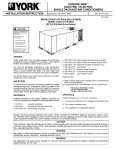
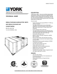
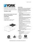
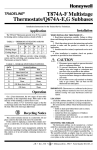
® SUNLINE 2000 ELECTRIC / ELECTRIC SINGLE PACKAGE AIR CONDITIONERS INSTALLATION INSTRUCTION 530.18-N9Y (995) Supersedes: 530.18-N9Y (693) 035-13091 MODELS D3CE090, 102, 120 (STYLE B) & D4CE150 (STYLE A) (8.5-9.0 EER) 208/230/460 VOLT MODELS ONLY GENERAL YORK Model DCE units are single package air conditioners designed for outdoor installation on a rooftop or a slab. These units can be equipped with field installed electric heaters for cooling/heating applications. The units are completely assembled on rigid, permanently attached base rails. All piping, refrigerant charge, and electrical wiring is factory installed and tested. The units require only electric power and duct connections at the point of installation. The electric heaters have nickel-chrome elements and utilize single point power connection. INSPECTION As soon as a unit is received, it should be inspected for possible damage during transit. If damage is evident, the extent of the damage should be noted on the carrier’s freight bill. A separate request for inspection by the carrier’s agent should be made in writing. Refer to Form 50.15-NM for additional information. 208/230/575 VOLT MODELS ONLY Renewal Parts: • Refer to the Renewal Parts Manual for complete listing of replacement parts on this equipment. All forms referenced in this instruction may be ordered from: Publications Distribution Center Unitary Products Group P.O. Box 1592, York, Pa. 17405 APPROVALS Design certified by U.L. & CGA as follows: 1. For use as a cooling only unit or a cooling unit with supplemental electric heat. 2. For outdoor installation only. 3. For installation on combustible material. REFERENCE Additional information on the design, installation, operation and service of this equipment is available in the following reference forms: • • • • • • • 55.70-N1 - General Installation 55.70-N2 - Pre-start & Post-start Check List 530.18-N9.1V - Electric Heater Accessory 530.18-N3.2V - Economizer Accessory 530.18-N3.4V - Motorized Outdoor Air Damper Accy. 530.18-N3.5V - Fuse Block Accessory 690.15-N25V - Low Ambient Accessory CAUTION THIS PRO DUCT M UST BE INSTALLED IN STRICT COMPLIANCE W ITH THE ENCLOSED INSTALLATION INSTRUCTIONS AND ANY APPLICABLE LOCAL, STATE, AND NATIONAL CODES INCLUDING, BUT NOT LIMITED TO, BUILDING, ELECTRICAL, AND MECHANICAL CODES. WARNING INCORRECT INSTALLATION MAY CREATE A CONDITION WHERE THE OPERATION OF THE PRODUCT COULD CAUSE PERSONAL INJURY OR PROPERTY DAMAGE. Installer should pay particular attention to the words: NOTE, CAUTION and WARNING. Notes are intended to clarify or make the installation easier. Cautions are given to prevent equipment damage. Warnings are given to alert installer that personal injury and/or equipment damage may result if installation procedure is not handled properly. 530.18-N9Y TABLE OF CONTENTS General ................................................................................ 1 Inspection............................................................................. 1 Reference ............................................................................ 1 Approvals ............................................................................. 1 Nomenclature....................................................................... 2 MAINTENANCE Normal Maintenance.......................................................... 14 TABLES No. INSTALLATION Limitations............................................................................ 3 Location ............................................................................... 3 Rigging and Handling .......................................................... 3 Clearances........................................................................... 3 Ductwork .............................................................................. 3 Barometric Relief / Fixed Outdoor Air Intake Damper Assembly.................................................... 4 Filters ................................................................................... 4 Condensate Drain................................................................ 4 Service Access..................................................................... 4 Thermostat........................................................................... 4 Power and Control Wiring.................................................... 5 Electric Heaters.................................................................... 5 Compressors........................................................................ 5 Optional Economizer / Mot. Damper Rain Hood ................. 5 Description Page 1 Unit Application Data .................................. 3 2 Physical Data.............................................. 7 3 Electrical Data............................................. 8 4 Blower Performance (7-1/2 & 8-1/2 Ton) .... 11 5 Blower Performance (10 & 12-1/2 Ton) ...... 12 6 Accessory Static Resistances .................... 12 7 Blower Motor and Drive Data ..................... 13 8 Heat Anticipator Setting .............................. 14 9 Blower Motor Pulley Adjustment................. 15 FIGURES No. Description 1 Center of Gravity......................................... 2 Barometric Relief / Fixed Outdoor Air OPERATION Cooling System.................................................................. 12 Preliminary Operation Cooling........................................... 12 Cooling Sequence of Operation ........................................ 12 Safety Controls .................................................................. 12 Heating Sequence of Operation ........................................ 12 Heat Anticipator Setpoints ................................................. 13 Checking Supply Air CFM.................................................. 13 Secure Owner’s Approval .................................................. 14 Page 3 Intake Damper Assembly......................... 4 3 Recommended Drain Piping....................... 4 4 Econo. / Mot. Damper Hood Assembly ...... 6 5 Adjusting Enthalpy Setpoint........................ 7 6 Typical Field Wiring..................................... 9 7 Dimensions and Clearances....................... 10 8 Pressure Drop versus Supply Air CFM....... 14 PRODUCT NOMENCLATURE D 3 C E 0 9 0 A 2 5 VOLTAGE CODE PRODUCT CATEGORY D = Single PackageAir Conditioner (Air Cooled) 25 = 208/230-3-60 46 = 460-3-60 58 = 575-3-60 FACTORY INSTALLED HEAT PRODUCT GENERATION NOMINAL COOLING CAPACITY 3 = 3rd Generation 4 = 4th Generation PRODUCT IDENTIFIER CE = Cooling 2 A = No Heat Installed 090 = 7-1/2 Tons 102 = 8-1/2 Tons 120 = 10 Tons 150 = 12-1/2 Tons Unitary Products Group 530.18-N9Y INSTALLATION LIMITATIONS These units must be installed in accordance with the following national and local safety codes: In U.S.A.: unit by attaching chain or cable slings to the lifting holes provided in the base rails. Spreaders, whose length exceeds the largest dimension across the unit, MUST be used across the top of the unit. BEFORE LIFTING A UNIT, MAKE SURE THAT ITS WEIGHT IS DISTRIBUTED EQUALLY ON THE CABLES SO THAT IT WILL LIFT EVENLY. 1. National Electrical Code ANSI/NFPA No. 70. 2. Local electric utility requirements. In Canada: Units may also be moved or lifted with a forklift. Slotted openings in the base rails are provided for this purpose. 1. Current Canadian Electrical Code C22.1 2. Current Installation Codes CAN/CGA-B149.1 and .2. LENGTH OF FORKS MUST BE A MINIMUM OF 54". Refer to Table 1 for Unit Application Data. Remove the nesting brackets from the four corners on top of the unit. All screws that are removed when taking these brackets off must be replaced on the unit. If components are to be added to a unit to meet local codes, they are to be installed at the dealer’s and/or the customer’s expense. Size of unit for proposed installation should be based on heat loss/heat gain calculation made according to the methods of Air Conditioning Contractors of America (ACCA). Refer to Table 2 for unit weights and to Figure 1 for approximate center of gravity. TABLE 1 - UNIT APPLICATION DATA Model DCE 090 208 / 230V Voltage 460V Variation Min. / Max.1 575V Wet Bulb Temperature (°F) of Air on Evaporator Coil, Min. / Max. Dry Bulb Temperature (°F) of Air on Condenser Coil, Min.2 / Max. DCE DCE 102 120 187 / 253 414 / 506 518 / 630 DCE 150 57 / 72 Dim. A B 45 / 120 1 Utilization range “A” in accordance with ARI Standard 110. 2 A low ambient accessory is available for operation down to 0°F. LOCATION Use the following guidelines to select a suitable location for these units. Unit Size (Tons) 7-1/2 8-1/2 10 12-1/2 33-1/4" 32" 32-1/2" 32-1/2" 47-1/2" 44-1/2" 46-3/4" 45" FIG. 1 - CENTER OF GRAVITY CLEARANCES All units require certain clearances for proper operation and service. Refer to Figure 7 for the clearances required for combustible construction, servicing, and proper unit operation. 1. Unit is designed for outdoor installation only. WARNING: Do not permit overhanging structures or shrubs to obstruct outdoor air discharge outlet. 2. Condenser must have an unlimited supply of air. Where a choice of location is possible, position the unit on either north or east side of building. DUCTWORK 3. For ground level installation, use a level concrete slab with a minimum thickness of 4 inches. The length and width should be at least 6 inches greater than the unit base rails. Do not tie slab to the building foundation. 4. Roof structure must be able to support the weight of the unit and its options and/or accessories. Unit must be installed on a solid level roof curb or appropriate angle iron frame. CAUTION: If a unit is to be installed on a roof curb or special frame other than a YORK roof curb, gasketing must be applied to all surfaces that come in contact with the unit underside. 5. Maintain level tolerance to 1/2" maximum across the entire length or width of the unit. RIGGING AND HANDLING Exercise care when moving the unit. Do not remove any packaging until the unit is near the place of installation. Rig the Unitary Products Group Ductwork should be designed and sized according to the methods in Manual Q of the Air Conditioning Contractors of America (ACCA). A closed return duct system shall be used. This shall not preclude use of economizers or outdoor fresh air intake. The supply and return air duct connections at the unit should be made with flexible joints to minimize noise. The supply and return air duct systems should be designed for the CFM and static requirements of the job. They should NOT be sized to match the dimensions of the duct connections on the unit. CAUTION: When fastening ductwork to side duct flanges on unit, insert screws through duct flanges only. DO NOT insert screws through casing. Outdoor ductwork must be insulated and waterproofed. Refer to Figure 7 for information concerning side and bottom supply and return air duct openings. 3 530.18-N9Y BAROMETRIC RELIEF / FIXED OUTDOOR AIR INTAKE DAMPER ASSEMBLY This damper assembly is shipped inside of the return air compartment. It serves as a barometric relief damper on units with economizer or as a fixed outdoor air intake damper on units less economizer. On units with bottom return, install the damper assembly over the opening in the side return air duct cover. (See Figure 2.) Remove the adhesive backed label covering this opening before installing the damper assembly. On units with side return, install the damper assembly in the return air ductwork as close to the unit as possible. Cut an opening 11-1/2" high by 17-1/2" wide in the ductwork to accommodate the damper device. FILTERS 2" filters are supplied with each unit. 1" replacement filters may be used with no modification to the filter racks. Filters must always be installed ahead of the evaporator coil and must be kept clean or replaced with same size and type. Dirty filters will reduce the capacity of the unit and will result in frosted coils or safety shutdown. Minimum filter area and required sizes are shown in Table 2. CONDENSATE DRAIN Plumbing must conform to local codes. Use a sealing compound on male pipe threads. Install a condensate drain line from the 3/4" female connection on the unit to spill into an open drain. NOTE: The condensate drain line MUST be trapped to provide proper drainage. See Figure 3. Attach the damper assembly into position by drilling six (6) holes, 9/64" dia. (#26 drill), using the holes in the hood flanges as a template and secure with the screws provided. On units less economizer, adjust the damper to the desired air flow opening by moving the damper bracket (inside of the hood) to one of the 3 positions provided. Position 1 will allow approximately 25% recirculated air flow, position 2 approximately 15% and position 3 approximately 10%. A screw on each side of the hood secures this bracket in place. FIG. 3 - RECOMMENDED DRAIN PIPING SERVICE ACCESS Access to all serviceable components is provided by five removable panels: • • • • • Compressor compartment Heater compartment Blower compartment Main control box Filter compartment Refer to Figure 7 for location of these access panels. THERMOSTAT FIG. 2 - BAROMETRIC RELIEF / FIXED OUTDOOR AIR DAMPER ASSEMBLY 4 The room thermostat should be located on an inside wall approximately 56" above the floor where it will not be subject to drafts, sun exposure or heat from electrical fixtures or appliances. Follow manufacturer’s instructions enclosed with thermostat for general installation procedure. Color coded insulated wires (#18 AWG) should be used to connect thermostat to unit. Five conductors are required for cooling units with no electric heat - seven are required for cooling units with electric heat. Unitary Products Group 530.18-N9Y POWER AND CONTROL WIRING Field wiring to the unit must conform to provisions of the National Electrical Code, ANSI / NFPA No. 70 (in U.S.A.), current Canadian Electrical Code C22.1 (in Canada) and/or local ordinances. The unit must be electrically grounded in accordance with NEC and CEC (as specified above) and/or local codes. Voltage tolerances which must be maintained at the compressor terminals during starting and running conditions are indicated on the unit Rating Plate and Table 1. The internal wiring harness furnished with this unit is an integral part of a UL and C.G.A. design certified unit. Field alteration to comply with electrical codes should not be required. A fused disconnect switch should be field provided for the unit. The switch must be separate from all other circuits. Wire entry at knockout openings require conduit fittings to comply with NEC (in U.S.A.), CEC (in Canada) and/or local codes. Refer to Figure 7 for installation location. If any of the wire supplied with the unit must be replaced, replacement wire must be of the type shown on the wiring diagram. Refer to Table 3 for electrical data. Electrical line must be sized properly to carry the load. USE COPPER CONDUCTORS ONLY. Each unit must be wired with a separate branch circuit fed directly from the meter panel and properly fused. CAUTION: When connecting electrical power and control wiring to the unit, waterproof type connectors MUST BE USED so that water or moisture cannot be drawn into the unit during normal operation. The above waterproofing conditions will also apply when installing a field-supplied disconnect switch. Refer to Figure 6 for typical field wiring and to the appropriate unit wiring diagram for control circuit and power wiring information. ELECTRIC HEATERS Electric heaters are available as field-installed accessories. Refer to Form 530.18-N9.1V for accessory instruction. These UL and C.G.A. approved heaters are located within the central compartment of the unit (see Figure 7 for access panel) with the heating elements extending into the supply air chamber. All accessory heaters contain a single point power supply kit. Fuses are supplied, where required, with the heater accessory. Some KW sizes require fuses and others do not. Refer to the accessory instruction for electrical data. COMPRESSORS The compressors are mounted on springs which have been tightened down for shipment only. After the unit is installed, back out the compressor bolts until the sleeve clears the top grommet. OPTIONAL ECONOMIZER / MOTORIZED DAMPER RAIN HOOD The following procedure should be used when assembling an economizer rain hood onto a unit. The outdoor and return air dampers, the damper actuator, the damper linkage, the outdoor and return air divider baffles and all the control sensors are factory mounted as part of the economizer option All of the hood components, including the filters, the gasketing and the hardware for assembling are packaged and located within the unit filter secion. (See Figure 4). 1. With filter section access panel removed, take out the hood components, filters, gasketing and hardware described above. Remove and discard the outdoor air opening cover on back of the unit. 2. Assemble the rain hood per the following procedures: a) Apply gasketing to all hood components as follows: -To the top outside surface and to the flange (toward unit) of each side plate. Extend gasketing 1/4" beyond the top and bottom of the flange to insure adequate sealing. -To the edge and flanges (in one continuous length) on each side of the center filter support. -To the top flange of the bottom filter support (on the side facing the unit). -To the hood cover flange (only on unit sizes 10 tons and over). (No gasketing required on this flange for unit sizes under 10 tons.) Unitary Products Group 5 530.18-N9Y b) Attach two filter guide angles to the inside of each side plate using 3 screws for each angle. Note the hole locations on the angles for proper positioning when attaching them on the side plates. Tighten screws. c) Attach the two side plates to the center filter support using 4 screws on each side. Do not tighten screws. d) Attach the bottom filter support between the side plates using 2 screws on each side. Do not tighten screws. e) Attach the hood cover to the side plates using 3 screws on each side. Do not tighten screws. f) Set hood assembly on a flat surface to insure all components are plumb and now tighten all screws. 3. Attach the hood assembly over the outdoor air opening on the unit duct panel as follows: On unit sizes under 10 tons, the flange of the hood cover must be inserted in under the unit top cover flange. One screw in the unit cover flange must be removed and one screw (at the right hand corner of the unit cover flange) needs only to be loosened to allow the notched flange of the hood cover to slide into place. Replace and tighten the 2 screws. On unit sizes 10 ton and over, secure the hood flange to the duct panel with 3 screws. Use holes in the hood cover flange as a template and drill 3 holes, 9/64" dia. (#26 drill) into the duct panel. On all units, attach the hood side plate flanges to the duct panel by drilling 6 holes, 9/64" dia. (#26 drill) for each side plate at the dimples provided in the duct panel. Secure hood into position using 6 gasketed screws in each side plate. 4. Secure the flange on the hood cover to the duct panel with 3 screws. Use holes in the cover flange as a template and drill 3 holes, 9/64" dia. (#26 drill) into the duct panel. 5. Insert two (2) 1" filters into the center of the hood, coming to rest in the center filter support at the back of the hood. Press filters up against the filter guide angles on the side plates and use 1 screw (B) on each side of hood to hold into position. Insert two (2) 1" filters into the bottom filter support per the same procedures as the center filters. NOTE: Install filters so that “Air Flow” arrows point upward, toward the unit. ENTHALPY SETPOINT ADJUSTMENT CAUTION: Extreme care must be exercised in turning both the setpoint and minimum position adjusting screws to prevent twisting them off. 6. The enthalpy set point for the dampers may now be set by selecting the desired setpoint shown in Figure 5. Adjust as follows: • For a single enthalpy (Model 2EE04700324), carefully • turn the set point adjusting screw to the “A”, “B”, “C” or “D” setting corresponding to the lettered curve. For a dual enthalpy (Model 2EE04700424), carefully turn the set point adjusting screw fully clockwise past the “D” setting. 7. To check that the damper blades move smoothly without binding, carefully turn the minimum position adjusting screw fully clockwise and then energize and de-energize terminals “R” to “G”. With terminals “R” to “G” energized, turn the minimum position screw counterclockwise until the desired minimum position has been attained. 8. Replace the filter section access panel. FIG. 4 - ECONOMIZER / MOTORIZED DAMPER RAIN HOOD ASSEMBLY (OPTION) 6 Unitary Products Group 530.18-N9Y FIG. 5 - ENTHALPY SETPOINT ADJUSTMENT Unitary Products Group 7 530.18-N9Y TABLE 2 - PHYSICAL DATA DCE 090 102 120 150 CENTRIFUGAL BLOWER (Dia. x Wd. in.) 12 x 12 12 x 12 15 X 12 15 x 12 EVAPORATOR FAN MOTOR HP (STANDARD) 1-1/2 2 2 3 BLOWER FAN MOTOR HP (ALTERNATE) 2 3 3 5 ROWS DEEP 4 4 4 4 EVAPORATOR FINS PER INCH 15 15 15 15 COIL FACE AREA (Sq. Ft.) 7.8 9.1 10.9 13.4 24 ea. 24 ea. 24 ea. 24 ea. OUTDOOR PROPELLER DIA. (in.) FAN MOTOR HP 1/2 ea. 1/2 ea. 1/2 ea. 3/4 ea. FAN (Two Per Unit) NOM. CFM TOTAL 2900 ea. 3200 ea. 3600 ea. 4400 ea. ROWS DEEP 2 2 2 2 CONDENSER FINS PER INCH 13 13 13 13 COIL FACE AREA (Sq. Ft.) 16.7 20.0 24.0 29.3 QUANTITY PER UNIT (12" X 24" X 2") 2 2 AIR QUANTITY PER UNIT (16" X 24" X 2") 2 2 2 3 FILTERS QUANTITY PER UNIT (18" X 24" X 2") 2 2 (SEE NOTE) TOTAL FACE AREA (sq. ft.) 9.3 9.3 11.3 14.0 SYSTEM NO. 1 6/8 7/4 8/0 10/4 REFRIGERANT 22 CHARGE (lbs./oz.) SYSTEM NO. 2 6/8 7/11 8/12 10/8 MODEL WEIGHTS (LBS) 7-1/2 Ton 8-1/2 Ton BASIC UNIT 10 Ton 12-1/2 Ton ACCESSORIES 9 KW 18 KW Electric Heat 24 KW (Nominal KW) 36 KW 54 KW Economizer Motorized Outdoor Air Damper Roof Mounting Curb 1000 1025 1100 1250 19 24 27 30 37 77 75 155 NOTE: Filter racks are adapted for 1" or 2" thick filters. TABLE 3 - ELECTRICAL DATA MODEL POWER SUPPLY 208/230-3-60 460-3-60 575-3-60 208/230-3-60 D3CE102 460-3-60 575-3-60 208/230-3-60 D3CE120 460-3-60 575-3-60 208/230-3-60 D4CE150 460-3-60 575-3-60 D3CE090 NOTES: 8 COMPRESSOR (#1 and #2) RLA EACH 14.1 7.1 5.8 16.0 8.3 7.1 16.7 9.6 8.3 21.8 9.6 9.0 LRA EACH 130 64 52 137 69 58 150 73 62 158 79 65 SUPPLY TOTAL MIN. OUTDOOR AIR UNIT WIRE MAX. FAN BLOWER AMPACITY, SIZE,2 FUSE MOTOR, MOTOR, AWG 1 AMPS SIZE (#1 & #2) FLA FLA AMPS EACH 1.5HP 2HP 3HP 5HP 1.5HP 2HP 3HP 5HP 1.5HP 2HP 3HP 5HP 2.3 1.3 1.3 2.3 1.3 1.3 2.3 1.3 1.3 3.5 2.5 2.5 5.7 2.6 2.1 - 7.5 3.4 2.7 7.5 3.4 2.7 7.5 3.4 2.7 - 42.0 43.8 21.1 21.9 17.7 18.3 48.2 51.3 10.6 24.8 26.2 4.8 21.2 22.4 3.9 49.6 52.7 10.6 27.6 29.0 4.8 24.1 25.3 3.9 66.6 71.1 10.6 15.1 31.4 34.1 4.8 7.5 29.1 31.1 3.9 5.9 50 25 20 60 30 25 60 35 30 80/90 40 35/40 8 12 14 - 8 12 14 8 12 12 8 10 12 - 6 10 12 6 10 10 4 8 8 4 8 8 1. Dual element, time delay type. Amps shown as “80/90" indicates rating for LO HP / HI HP respectively. Maximum HACR breaker of the same AMP size is applicable, except 575 volt units. 2. Based on 75°C copper conductorss. Unitary Products Group 530.18-N9Y 24 Volt Thermostat 2TH04701024 or (2TH04701524 w/Subbase 2TB04700324). Second stage heating is not required on units with a single stage electric heater. 1 2 FIG. 6 - TYPICAL FIELD WIRING Unitary Products Group 9 530.18-N9Y RETURN AIR SUPPLY AIR CONDENSER AIR OUTDOOR AIR (Economizer) All dimensions are in inches. They are subject to change without notice. Certified dimensions will be provided upon request. UTILITIES ENTRY DATA HOLE A KNOCKOUT SIZE (DIA.) 3/4" 7/8" B 2" USED FOR Side Control Wiring Bottom* Power Wiring (Side or Bottom)* *Knockouts in the bottom of the unit can be located by the slice in the insulation. DUCT COVERS - Units are shipped with all air duct openings covered. For side duct applications; 1. Remove and discard the supply and return air duct covers. 2. Connect ductwork to duct flanges on the rear of the unit. For bottom duct applications; 1. Remove the side supply and return air duct covers to gain access to the bottom supply and return air duct covers. 2. Remove and discard the bottom duct covers. 3. Replace the side duct covers. CLEARANCES Front Back Left Side (Filter Access) Right Side (Cond. Coil) Below Unit1 Above Unit2 24" 12" (Less Economizer) 36" (With Economizer) 24" (Less Economizer) 54" (With Economizer) 24" 20" 72" with 36" maximum Horizontal Overhang (For Condenser Air Discharge) NOTE: Units and ductwork are approved for zero clearance to combustible materials when equipped with electric heaters. 1 Units (applicable in U.S.A. only) may be installed on combustible floors made from wood or class A, B or C roof covering material. Units must be installed oudoors. Overhanging structures or shrubs should not obstruct condenser air discharge outlet. 2 DETAIL “X” (SIDE SUPPLY AND RETURN AIR OPENING) FIG. 7 - DIMENSIONS & CLEARANCES (7-1/2 - 12-1/2 TON) 10 Unitary Products Group 530.18-N9Y TABLE 4 - SUPPLY AIR BLOWER PERFORMANCE (7-1/2 & 8-1/2 TON) MODEL DCE090 - (SIDE DUCT APPLICATIONS) BLOWER SPEED, RPM 975 1025 1070 1130 1175 1220 ESP 0.93 1.08 1.22 1.41 1.61 1.78 2250 BHP 1.16 1.21 1.32 1.43 1.51 1.66 KW 1.08 1.13 1.23 1.33 1.41 1.55 ESP 0.79 0.95 1.08 1.29 1.49 1.66 2550 BHP 1.27 1.34 1.46 1.57 1.67 1.81 KW 1.18 1.25 1.36 1.46 1.56 1.69 ESP 0.53 0.68 0.83 1.02 1.23 1.39 CFM 3000 BHP 1.45 1.54 1.68 1.83 1.92 2.10 KW 1.35 1.44 1.57 1.71 1.79 1.96 ESP 0.29 0.42 0.58 0.77 0.96 - 3400 BHP 1.65 1.75 1.89 2.04 2.18 - KW 1.54 1.63 1.76 1.90 2.03 - ESP 0.17 0.32 - 3750 BHP 1.97 2.11 - KW 1.84 1.97 - ESP 0.40 0.55 0.70 0.89 1.10 1.26 CFM 3000 BHP 1.45 1.54 1.68 1.83 1.92 2.10 KW 1.35 1.44 1.57 1.71 1.79 1.96 ESP 0.12 0.25 0.41 0.60 0.79 - 3400 BHP 1.65 1.75 1.89 2.04 2.18 - KW 1.54 1.63 1.76 1.90 2.03 - ESP 0.12 - 3750 BHP 2.11 - KW 1.97 - MODEL DCE090 - (BOTTOM DUCT APPLICATIONS) BLOWER SPEED, RPM 975 1025 1070 1130 1175 1220 ESP 0.86 1.01 1.15 1.34 1.54 1.71 2250 BHP 1.16 1.21 1.32 1.43 1.51 1.66 KW 1.08 1.13 1.23 1.33 1.41 1.55 ESP 0.70 0.86 0.99 1.20 1.40 1.57 2550 BHP 1.27 1.34 1.46 1.57 1.67 1.81 KW 1.18 1.25 1.36 1.46 1.56 1.69 MODEL DCE102 - (SIDE DUCT APPLICATIONS) BLOWER SPEED, RPM 975 1025 1070 1130 1175 1220 CFM ESP 0.79 0.95 1.08 1.29 1.49 1.66 2550 BHP 1.27 1.34 1.46 1.57 1.67 1.81 KW 1.18 1.25 1.36 1.46 1.56 1.69 ESP 0.53 0.68 0.83 1.02 1.23 1.39 3000 BHP 1.45 1.54 1.68 1.83 1.92 2.10 KW 1.35 1.44 1.57 1.71 1.79 1.96 ESP 0.29 0.42 0.58 0.77 0.96 1.20 3400 BHP 1.65 1.75 1.89 2.04 2.18 2.37 KW 1.54 1.63 1.76 1.90 2.03 2.15 ESP 0.08 0.17 0.32 0.52 0.72 0.95 3750 BHP 1.62 1.97 2.11 2.22 2.34 2.78 KW 1.42 1.84 1.97 2.06 2.16 2.56 MODEL DCE102 - (BOTTOM DUCT APPLICATIONS) BLOWER SPEED, RPM 975 1025 1070 1130 1175 1220 NOTES: CFM ESP 0.70 0.86 0.99 1.20 1.40 1.57 2550 BHP 1.27 1.34 1.46 1.57 1.67 1.81 KW 1.18 1.25 1.36 1.46 1.56 1.69 ESP 0.40 0.55 0.70 0.89 1.10 1.26 3000 BHP 1.45 1.54 1.68 1.83 1.92 2.10 KW 1.35 1.44 1.57 1.71 1.79 1.96 ESP 0.12 0.25 0.41 0.60 0.79 0.91 3400 BHP 1.65 1.75 1.89 2.04 2.18 2.37 KW 1.54 1.63 1.76 1.90 2.03 2.15 ESP 0.12 0.24 0.42 0.58 3750 BHP 2.11 2.22 2.34 2.78 KW 1.97 2.06 2.16 2.56 1. Blower performance includes a wet evaporator coil and 2" filters. 2. Units include a baffle to direct the proper flow of air across the electric heaters. On “cooling only” applications, this baffle MUST be removed to get the ESP values listed in the above tables. 3. Refer to Table 6 for the resistance of the unit accessories. ESP = External Static Pressure available for the supply and return air duct sytem. All internal unit resistances have been deducted from the total static pressure of the blower. = Larger Horsepower Alternate Motor Required. Unitary Products Group 11 530.18-N9Y TABLE 5 - SUPPLY AIR BLOWER PERFORMANCE (10 & 12-1/2 TON) MODEL DCE120 - (SIDE DUCT APPLICATIONS) BLOWER SPEED, RPM 860 915 950 1000 1050 1090 ESP 1.14 1.32 1.51 1.69 1.89 2.08 3000 BHP 1.40 1.55 1.68 1.83 1.98 2.12 KW 1.31 1.45 1.57 1.71 1.84 1.97 ESP 0.98 1.18 1.37 1.57 1.78 1.97 3500 BHP 1.58 1.76 1.91 2.07 2.25 2.41 KW 1.48 1.64 1.78 1.93 2.10 2.24 ESP 0.77 0.95 1.15 1.35 1.57 1.78 CFM 4000 BHP 1.80 1.98 2.14 2.33 2.55 2.72 KW 1.68 1.85 2.00 2.17 2.37 2.54 ESP 0.53 0.72 0.91 1.14 1.35 1.55 4500 BHP 2.05 2.23 2.43 2.62 2.86 3.06 KW 1.91 2.08 2.27 2.45 2.67 2.86 ESP 0.25 0.49 0.67 0.92 1.12 - 5000 BHP 2.31 2.48 2.72 2.91 3.17 - KW 2.15 2.31 2.54 2.72 2.96 - ESP 0.54 0.72 0.92 1.12 1.34 1.55 CFM 4000 BHP 1.80 1.98 2.14 2.33 2.55 2.72 KW 1.68 1.85 2.00 2.17 2.37 2.54 ESP 0.23 0.42 0.61 0.84 1.05 1.25 4500 BHP 2.05 2.23 2.43 2.62 2.86 3.06 KW 1.91 2.08 2.27 2.45 2.67 2.86 ESP 0.13 0.31 0.56 0.76 - 5000 BHP 2.48 2.72 2.91 3.17 - KW 2.31 2.54 2.72 2.96 - ESP 0.67 0.92 1.12 1.37 1.45 1.62 CFM 5000 BHP 2.72 2.91 3.17 3.78 3.88 4.11 KW 2.54 2.72 2.96 3.53 3.62 3.83 ESP 0.38 0.62 0.89 1.05 1.12 1.29 5500 BHP 3.03 3.24 4.06 4.28 4.35 4.53 KW 2.83 3.03 3.79 3.99 4.06 4.22 ESP 0.28 0.46 0.69 0.88 0.96 1.15 6000 BHP 3.94 4.20 4.53 4.79 4.89 5.12 KW 3.67 3.91 4.22 4.46 4.56 4.77 ESP 0.31 0.56 0.76 1.01 1.09 1.26 CFM 5000 BHP 2.72 2.91 3.17 3.78 3.88 4.11 KW 2.54 2.72 2.96 3.53 3.62 3.83 ESP 0.02 0.26 0.53 0.69 0.76 0.93 5500 BHP 3.03 3.24 4.06 4.28 4.35 4.53 KW 2.83 3.03 3.79 3.99 4.06 4.22 ESP 0.27 0.46 0.54 0.73 6000 BHP 4.53 4.79 4.89 5.12 KW 4.22 4.46 4.56 4.77 MODEL DCE120 - (BOTTOM DUCT APPLICATIONS) BLOWER SPEED, RPM 860 915 950 1000 1050 1090 ESP 1.01 1.19 1.38 1.56 1.76 1.95 3000 BHP 1.40 1.55 1.68 1.83 1.98 2.12 KW 1.31 1.45 1.57 1.71 1.84 1.97 ESP 0.80 1.00 1.19 1.39 1.60 1.79 3500 BHP 1.58 1.76 1.91 2.07 2.25 2.41 KW 1.48 1.64 1.78 1.93 2.10 2.24 MODEL DCE150 - (SIDE DUCT APPLICATIONS) BLOWER SPEED, RPM 960 1000 1050 1090 1105 1140 ESP 1.15 1.35 1.57 1.78 1.89 2.06 4000 BHP 2.14 2.33 2.55 2.72 3.08 3.25 KW 2.00 2.17 2.37 2.54 2.87 3.03 ESP 0.91 1.14 1.35 1.55 1.68 1.84 4500 BHP 2.43 2.62 2.86 3.06 3.45 3.66 KW 2.27 2.45 2.67 2.86 3.22 3.41 MODEL DCE150 - (BOTTOM DUCT APPLICATIONS) BLOWER SPEED, RPM 960 1000 1050 1090 1105 1140 NOTES: ESP 0.92 1.12 1.34 1.55 1.66 1.83 4000 BHP 2.14 2.33 2.55 2.72 3.08 3.25 KW 2.00 2.17 2.37 2.54 2.87 3.03 ESP 0.61 0.84 1.05 1.25 1.38 1.54 4500 BHP 2.43 2.62 2.86 3.06 3.45 3.66 KW 2.27 2.45 2.67 2.86 3.22 3.41 1. Blower performance includes a wet evaporator coil and 2" filters. 2. Units include a baffle to direct the proper flow of air across the electric heaters. On “cooling only” applications, this baffle MUST be removed to get the ESP values listed in the above tables. 3. Refer to Table 6 for the resistance of the unit accessories. ESP = External Static Pressure available for the supply and return air duct sytem. All internal unit resistances have been deducted from the total static pressure of the blower. = Larger Horsepower Alternate Motor Required. TABLE 6 - ACCESSORY STATIC RESISTANCES* EXTERNAL STATIC PRESSURE DROP - RESISTANCE, IWG CFM 2250 3000 4000 5000 6000 Economizer/Motorized Damper 0.02 0.02 0.03 0.05 0.07 99 KW 1 0.06 0.11 0.20 0.31 0.45 18 KW 0.06 0.12 0.21 0.33 0.48 Electric Heaters 24 KW 36 KW 0.07 0.13 0.23 0.35 0.52 54 KW 2 0.15 0.26 0.40 0.58 DESCRIPTION 12 *Deduct these resistance values from the available external static pressure shown in the respective Blower Performance Table. 1 9 KW Heater is only available on 7-1/2 and 8-1/2 Ton Units. 2 54 KW Heater is only available on 10 and 12-1/2 Ton Units. Unitary Products Group 530.18-N9Y TABLE 7 - BLOWER MOTOR AND DRIVE DATA MODELS DCE090 BLOWER RANGE (RPM) MOTOR* HP 1-1/2 2 2 3 2 860-1090 3 860-1090 3 ADJUSTABLE FIXED MOTOR PULLEY BLOWER PULLEY PITCH PITCH EFFICIENCY BORE BORE DIA. DIA. (%) (IN.) (IN.) (IN.) (IN.) BELTS PITCH LENGTH (IN.) DESIGNATION QTY 1 50.3 A49 1 6.2 1 50.3 A49 1 7/8 7.0 1 57.3 A56 1 3.4 - 4.4 7/8 7.0 1 57.3 1-1/8 8.9 1 62.8 A56 BX61 (Notched) 1 4.9 - 5.9 SERVICE FACTOR FRAME SIZE 1.20 56 82.0 3.4 - 4.4 7/8 6.2 1.20 56 82.0 3.4 - 4.4 7/8 1.20 56 82.0 3.4 - 4.4 1.20 56 82.0 1.15 184 82.0 975-1220 DCE102 DCE120 DCE150 960 - 1140 5 1 * All motors are 1750 RPM, have solid bases and are inherently protected. These motors can be selected to operate into their service factor because they are located in the moving air, upstream of any heating device. OPERATION COOLING SYSTEM The cooling section is a complete factory package utilizing an air-cooled condenser. The system is factory-charged with Refrigerant-22. The compressors are hermetically sealed, internally sprung and base-mounted on spring isolators. The compressors also have inherent (internal) protection. If there is an abnormal temperature rise in a compressor, the protector will open to shut down the compressor. 3. A Low Pressure Switch to protect against loss of refrigerant charge. If either one of the above safety controls opens, that individual refrigerant system will bo locked out. The other refrigerant system will continue in operation unless it too is effected by the same fault. The lock out of either system can be reset by opening the 24V circuit either at the room thermostat or at the unit disconnect. HEATING SEQUENCE OF OPERATION PRELIMINARY OPERATION COOLING SEQUENCE OF OPERATION WITH ELECTRIC HEAT After installation has been completed, energize the crankcase heaters for at least four hours before operating unit. After this initial warm-up, the compressors should be given three false starts (energized just long enough to make a few revolutions) with 5-7 minutes delay between each start before being put into full time service. WITH POWER TO UNIT AND THERMOSTAT IN THE HEATING MODE NOTE: Prior to each cooling season, the crankcase heaters must be energized at least 10 hours before system is put into operation. COOLING SEQUENCE OF OPERATION When the thermostat calls for “first-stage” cooling, the low voltage control circuit from “R” to “G” and “Y1" (wiring schematic) is completed to energize compressor #1, condenser fan motor #1 and blower motor simultaneously. When the thermostat calls for “2nd-stage” cooling, the low voltage control circuit from “R” to “Y2" is completed to energize compressor #2 and condenser fan motor #2. Single-stage heating: (applies only to 9 KW heater, all other heaters MUST use a two-stage thermostat:) a) If the fan switch is in the "ON" position, the evaporator blower motor contactor (3M) will be energized through terminal G to provide continuous blower operation. If the fan switch is in the "AUTO" position, the blower will operate only when there is a call for heating by the thermostat. b) Upon a call for heat by the thermostat, the heater contactor (4M) will be energized. c) The thermostat will cycle the electric heat to satisfy the heating requirements of the conditioned space. Two-stage heating: (applies to all heaters except 9 KW): After the thermostat is satisfied and opens, all components likewise stop simultaneously. a) If the fan switch is in the "ON" position, the evaporator blower motor contactor (3M) will be energized through terminal G to provide continuous blower operation. If the fan switch is in the "AUTO" position, the blower will operate only when there is a call for heating by the thermostat. SAFETY CONTROLS b) Upon a call for first-stage heat by the thermostat, the heater contactor (4M) will be energized. Each refrigerant system is equipped with the following safety controls: 1. A Suction Line Freezestat to protect aginst low evaporator temperatures due to a low air flow or a low return air temperature. 2. A High Pressure Cutout Switch to protect against excessive discharge pressures due to a blocked condenser coil or a condenser motor failure. Unitary Products Group If the second stage of heat is required, heater contactor (5M) will be energized. Note that on the 54 KW 240V heater that heater contactors (5M and 6M) will be energized. c) The thermostat will cycle the electric heat to satisfy the heating requirements of the conditioned space. CONTINUOUS BLOWER - Continuous blower operation is possible by closing the R to G circuit on the thermostat. 13 530.18-N9Y HEAT ANTICIPATOR SETPOINTS It is important that the anticipator setpoint be correct. Too high of a setting will result in longer heat cycles and a greater temperature swing in the conditioned space. Reducing the value below the correct setpoint will give shorter “ON” cycles and may result in the lowering of the temperture within the conditioned space. Refer to Table 8 for the required heat anticipator setting. TABLE 8 - HEAT ANTICIPATOR SETTING HEATER KW 9 18 24 36 54 9 18 24 36 54 9 18 24 36 54 VOLTAGE 240-3-60 480-3-60 600-3-60 SETTING, AMPS TH1 TH2 0.40 0.45 0.45 0.45 0.45 0.45 0.45 0.90 0.45 0.40 0.40 0.40 0.40 0.40 0.40 0.40 0.29 0.40 0.40 0.40 0.40 0.40 0.40 0.40 0.40 0.45 0.40 CHECKING SUPPLY AIR CFM The RPM of the supply air blower will depend on the required CFM, the unit accessories and the static resistances of both the supply and the return air duct systems. With this information, the RPM for the supply air blower can be determined from the blower performance data in Tables 4 or 5. To check the supply air CFM after the initial balancing has been completed: 1.Remove the two 15/16" dot plugs from the holes in the blower motor access and filter access panels as shown in Figure 7. 2. Insert at least 8" of 1/4 inch tubing into each of these holes for sufficient penetration into the air flow on both sides of the evaporator (or indoor) coil. NOTE: The tubes must be inserted and held in a position perpendicular to the air flow so that velocity pressure will not affect the static pressure readings. 3. Using an inclined manometer, determine the pressure drop across a dry indoor coil. Since the moisture on an indoor coil may vary greatly, measuring the pressure drop across a wet coil under field conditions would be inaccurate. To assure a dry coil, the compressors should be deactivated while the test is being run. 4. Knowing the pressure drop across a dry coil, the actual CFM through the unit can be determined from the curve in Figure 8. WARNING: Failure to properly adjust the total system air quantity can result in extensive blower damage. After readings have been obtained, remove the tubes and seal up the drilled holes in the side panels. 5/16" dot plugs (P/N 029-13880) are available through normal parts ordering procedures. NOTE: DE-ENERGIZE THE COMPRESSORS BEFORE TAKING ANY TEST MEASUREMENTS TO ASSURE A DRY INDOOR COIL. Knowing the required blower RPM and the blower motor HP, the setting (turns open) for the supply air motor pulley can be determined from Table 9. BELT DRIVE BLOWER All units have belt drive single-speed blower motors. The variable pitch pulley on the blower motor can be adjusted to obtain the desired supply air CFM. Refer to Table 7 for blower motor and drive data. TABLE 9 - SUPPLY AIR BLOWER MOTOR PULLEY ADJUSTMENT TURNS OPEN* 5 4 3 2 1 0 BLOWER DRIVE RANGE (RPM) DCE090, 102 DCE120, 150 975 860 1024 906 1073 952 1122 998 1171 1044 1220 1090 *Pulleys can be adjusted in half-turn increments. Start the supply air blower motor. Adjust the resistances in both the supply and the return air duct systems to balance the air distribution throughout the conditioned space. The job specifications may require that this balancing be done by someone other than the equipment installer. 14 FIG. 8 - PRESSURE DROP ACROSS A DRY INDOOR COIL VS SUPPLY AIR CFM Unitary Products Group 530.18-N9Y SECURE OWNER’S APPROVAL: When the system is functioning properly, secure the owner’s approval. Show him the location of all disconnect switches and the thermostat. Teach him how to start and stop the unit and how to adjust temperature settings within the limitations of the system. MAINTENANCE NORMAL MAINTENANCE CAUTION: Prior to any of the following maintenance procedures, shut off all power to the unit to prevent personal injury. OUTDOOR COIL - Dirt should not be allowed to accumulate on the outdoor coil surface or other parts in the air circuit. Cleaning should be as often as necessary to keep coil clean. Use a brush, vacuum cleaner attachment, or other suitable means. If water is used to clean coil, be sure power to the unit is shut off prior to cleaning. FILTERS - Inspect once a month. Replace disposable or clean permanent type as necessary. DO NOT replace permanent type with disposable. NOTE: Exercise care when cleaning the coil so that the coil fins are not damaged. MOTORS - Indoor fan and outdoor fan motors are permanently lubricated and require no maintenance. Do not permit the outdoor air discharge to be obstructed by overhanging structures of shrubs. Unitary Products Group 15 Unitary Products Group P.O. Box 1592, York, Pennsylvania USA 17405-1592 Subject to change without notice. Printed in U.S.A Copyright by York International Corporation 1995. All Rights Reserved. SHU 8M 995 .88 Code: SBY 530.18-N9Y