1
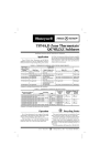
T874A-F Multistage
Thermostats/Q674A-E,G Subbases
TRADELINE®
Installation Instructions for the Trained Service Technician.
Application
Installation
The T874A-F Thermostats provide 24 to 30 Vac control
for heating and/or cooling systems as listed in Table 1.
WHEN INSTALLING THIS PRODUCT…
1. Read these instructions carefully. Failure to follow
them could damage the product or cause a hazardous condition.
2. Check the ratings given in the instructions and on the
product to make sure the product is suitable for your
application.
3. Installer must be a trained, experienced service technician.
4. After installation is complete, check out product
operation as provided in these instructions.
TABLE 1—THERMOSTAT HEATING AND/OR
COOLING STAGES.
T874
A
B
C
D
E
F
Heating Stages
1
1
2
2
—
2
Cooling Stages
1
2
1
2
2
—
The Q674A-E,G Subbases provide wiring terminals,
system and fan switching, and mounting bases for T874
Thermostats as listed in Table 2.
CAUTION
1. Disconnect power supply to prevent electrical
shock or equipment damage.
2. To prevent interference with the thermostat
linkage, keep wire length to a minimum and
run wires close as possible to the subbase.
3. Do not overtighten thermostat captive mounting screws because damage to subbase threads
can result.
4. Do not short across coil terminals on heating
relay or gas control. This can burn out the
thermostat heat anticipator.
TABLE 2—SUBBASE SWITCHING POSITIONS.
Q674
Model
Switch Positions
System
Fan
A
Heat-Auto-Cool
Auto-On
B
Heat-Off-Cool
Auto-On
C
Off-Auto
Auto-On
D
None
None
E
Off-Heat-Auto-Cool
Auto-On
G
Off-Auto
None
Operation
On a 2-heat thermostat, the two stages of heat make
sequentially as the temperature drops. Make refers to the
mercury switch initiating a call for heat or cool.
There are about 2° F [1° C] between stages so that the
second stage makes only when the first stage cannot handle
the load. This is the interstage differential.
M3375
Recycling Notice
This control contains mercury in a sealed tube. Do not
place control in the trash at the end of its useful life.
If this control is replacing a control that contains mercury in a sealed tube, do not place your old control in the
trash.
Contact your local waste management authority for
instructions regarding recycling and the proper disposal of
this control, or of an old control containing mercury in a
sealed tube.
IMPORTANT: Thermostats are calibrated at the factory
by using subbases mounted at true level. Inaccurate
subbase leveling will cause thermostat control deviation.
LOCATION
Locate the subbase about 5 ft [1.5m] above the floor in
an area with good air circulation at average temperature.
Do not mount the subbase where the thermostat may be
affected by:
— drafts or dead spots behind doors and in corners.
— hot or cold air from ducts.
— radiant heat from sun, appliances or fireplace.
— concealed pipes and chimneys.
— unheated (uncooled) areas such as an outside wall
behind the thermostat.
MOUNTING THE SUBBASE
The thermostat subbase can be mounted on a vertical
outlet box, horizontal outlet box or directly on the wall.
1. If you must mount the subbase on a vertical outlet
box, order Honeywell 193121A Adapter Assembly (Fig. 1).
The assembly includes an adapter ring, two screws and a
cover plate to cover marks on the wall. Install the ring and
cover plate on the vertical outlet box.
J.H. • Rev. 5-94 • 1
• ©Honeywell Inc. 1994 • Form Number 60-1165—6
60-1165—6
M3375
3. Secure the cover plate (if used) and subbase with the
screws provided. Do not fully tighten the subbase screws.
4. Level the subbase using a spirit level, as shown in
Fig. 3, and firmly tighten subbase mounting screws. The
subbase mounting holes provide for minor out-of-level
adjustments.
Fig. 1—Installation of subbase on outlet box.
IMPORTANT: An incorrectly leveled subbase will cause
the temperature control to deviate from setpoint.
Fig. 3—Subbase components and leveling
procedure.
For a wall installation, hold subbase in position and
mark holes for anchors. See Fig. 2. Obtain wall anchors
locally. Take care that the wires do not fall back into the
wall opening. Set aside subbase. Drill two 3/16 in.
[4.8 mm] holes and gently tap anchors into the holes
until flush with the wall.
WIRING THE SUBBASE
All wiring must comply with local electrical codes and
ordinances. Follow equipment manufacturer wiring instructions when available. To wire subbase, proceed as
follows:
1. Connect the system wires to the subbase as shown in
Figs. 8 through 16. A letter code is located near each
terminal for identification. The terminal barrier permits
straight or conventional wraparound wiring connections.
See Fig. 4.
Fig. 2—Installation of subbase on wall.
Fig. 4—Wiring connections.
2. Your Q674 Subbase can require one or more jumpers
that may or may not be factory supplied. Refer to the wiring
diagrams for specific terminals to be jumpered. See Table 3
for proper application.
2. Pull electrical wires through the cover plate (if
used) and subbase cable opening (Fig. 3). See Wiring the
Subbase section before pulling any wires.
CAUTION
Never install more than one wire per terminal
unless factory supplied jumper with spade terminal is used. See Fig. 7.
IMPORTANT: Use 18 gauge, color-coded thermostat
cable for proper wiring.
60-1165—6
2
TABLE 3—JUMPER APPLICATIONS.
If your subbase has: Application
RC, RH terminals
single transformer
system
5
adjacent terminals
special system
operation or LED
indication
6
nonadjacent
terminals
Fig. 6—Jumper adjacent terminals for special
system hookup. Strip wire 3/4 in. [19 mm].
Use Fig.
7
3. Firmly tighten each terminal screw.
4. Fit wires as close as possible to the subbase. Push
excess wire back into the hole.
5. Plug hole with nonflammable insulation to prevent
drafts from affecting the thermostat.
Fig. 5—Jumper RC and RH for single transformer system. Strip wire 3/4 in. [19 mm].
Fig. 7—For nonadjacent terminals, use jumper
supplied with subbase.
NOTE: Only the T874D Thermostat is shown with the
subbases. This thermostat/subbase provides 2-stage heating and 2-stage cooling connections. If using another
model, see Fig. 16 and Table 4.
TABLE 4—THERMOSTAT BULB
CONFIGURATOIN.
Model No.
Heating Bulbs
T874A
H1
Cooling Bulbs
C1
T874B
H1
C1,C2
T874C
H1, H2
C1
T874D
H1, H2
C1, C2
T874E
T874F
C1, C2
H1, H2
3
60-1165—6
Fig. 8—T874A-D/Q674A in standard heating/cooling system.
Fig. 9—T874C,D/Q674B in standard heating/cooling system with separate transformers for heating and
cooling.
SUBBASE
THERMOSTAT
SYSTEM COMPONENTS
L1
(HOT)
L2
RH
HEAT RELAY 1
3
W1
1
FAN
SWITCH
H1
FALL
1
HEAT RELAY 2
AUTO
W2
H1 ANTICIPATOR
HEAT CHANGEOVER
VALVE
ON
B
4
X1
H2
6
FALL
H2 ANTICIPATOR
SYSTEM
SWITCH
O
COOL CHANGEOVER
VALVE
8
HEAT
C1
RISE
G
OFF
9
FAN RELAY
2
COOL
Y2
COMPRESSOR
CONTACTOR 2
10
C1 ANTICIPATOR
Y1
C2 ANTICIPATOR
RISE
C2
RC
1
2
60-1165—6
11
COMPRESSOR
CONTACTOR 1
POWER SUPPLY. PROVIDE DISCONNECT MEANS AND OVERLOAD
PROTECTION AS REQUIRED.
JUMPER RH, RC FOR SINGLE TRANSFORMER.
3
4
OPTIONAL LED ON SOME MODELS.
L2
L1
(HOT)
1
M933C
Fig. 10—T874D/Q674B in standard heating/cooling system with single transformer for heating and
cooling. Exact replacement for York model no. 2TB04700324.
Fig. 11—T874D,E,F/Q674C in standard heating/cooling system.
5
60-1165—6
Fig. 12—T874A,D,F/Q674D in standard heating/cooling system.
Fig. 13—T874D/Q674E in standard heating/cooling system.
60-1165—6
6
Fig. 14—T874A-F/Q674G in standard heating/cooling system.
Fig. 15—T874C/Q674B in standard application.
7
60-1165—6
Fig. 16—Typical Q674 terminal designations. The thermostat and subbase used determines the number
of system components controlled.
TEMPERATURE LEVER STOPS
Some thermostats have factory-installed temperature
lever locking screws (Fig. 17) and/or stop brackets
(Fig. 18). Use these only if the HEAT and COOL temperature set point lever ranges are to be restricted. If the components are factory-installed, see the specific section below
for the adjustment procedure.
If a temperature range restriction is required and the
locking components are not factory-installed, it is necessary to order a 4074ECK Envelope Assembly. This envelope includes two stop brackets, one brass insert and one
bracket mounting screw for restricting the adjustable range
of the HEAT and COOL set point levers. Also, the envelope includes two screws with plastic insulated heads for
locking the set point control levers in position. If the
components are to be used, see the specific section below
for the installation procedure.
INSTALL AND ADJUST LOCKING LEVER
SCREWS
The two screws with insulated heads should be used
only if the HEAT and COOL levers are to be locked in
place at a specific temperature control point. Do not use
standard screws that provide metal-to-metal contact with
the lever brackets.
To install:
1. Refer to Fig. 20 for screw hole locations.
2. Install the two screws with insulated heads in the
indicated holes. Do not overtighten screws.
3. Set the HEAT lever and the COOL lever at desired
temperature control points.
4. Firmly tighten both screws.
INSTALL AND ADJUST STOP BRACKETS
Install the stop brackets only if there is a need to restrict
the adjustable range of the heating and cooling temperature
set point levers.
To install:
1. Turn to the back of the T874 Thermostat. Locate the
hole for the brass insert in the plastic base below the LED
window. See Fig. 19.
2. Push the brass insert into the hole with your finger.
3. Turn to the front of the T874 Thermostat.
4. Place the two stop brackets in position with the tabs
in the slot between the HEAT and COOL levers. See
Fig. 20.
5. Insert the mounting screw into the two slots in the
stop brackets and attach to the brass insert. Tighten the
screw to pull the brass insert into the back of the thermostat.
6. Loosen the mounting screw enough so the stop brackets can slide for adjustment.
7. Move the HEAT and COOL set point levers to the
maximum temperature that is desired.
8. Slide the stop brackets until one rests against the
HEAT lever and the other against the COOL lever.
Fig. 17—Location of lever locking screws.
LEVER LOCKING SCREWS
M18680
Fig. 18—Location of lever stop brackets.
LEVER STOP BRACKETS
M18681
60-1165—6
8
9. Firmly tighten the mounting screw.
10. If the HEAT and COOL levers are to be locked in
place at a specific temperature, use the two insulated head
screws supplied instead of the two adjustable lever stop
brackets.
MOUNTING THE THERMOSTAT
1. Remove the thermostat cover by pulling the bottom
edge of the cover upward until it snaps free of the cover clip.
NOTE: The cover is hinged at the top and must be removed
by pulling up at the bottom.
CAUTION
2. Carefully remove and discard the polystyrene packing
insert that protects the mercury switches during shipment.
3. Turn over the thermostat base and note the spring
fingers that engage the subbase contacts. Make sure the
spring fingers are NOT bent flat, preventing proper electrical contact with the subbase.
4. Set the adjustable heat anticipator indicators to the
respective current setting for each stage. See Setting the
Heat Anticipator section.
5. Note the two tabs on the top inside edge of the
thermostat base. The tabs fit into corresponding slots on top
of the subbase. Mount the thermostat on the subbase.
6. Align the two captive mounting screws in the thermostat base with the posts on the subbase. See Fig. 21.
Tighten both screws. Do not overtighten screws or damage
to subbase posts can result.
Do not use standard screws that provide metal-tometal contact with the stop brackets. Short circuit
and potential equipment damage may result.
Fig. 19—Installing brass insert.
LED WINDOW
Fig. 21—Mounting thermostat on subbase.
BRASS INSERT
INSERT HOLE
BACK OF
THERMOSTAT
M955A
Fig. 20—Installing stop brackets.
HOLES FOR INSULATED
LOCKING LEVER SCREWS
COOL
LEVER
HEAT
LEVER
HOLE WITH
BRASS INSERT
BRACKET
TABS
Settings
ADJUSTABLE
LEVER STOP
BRACKETS
BRACKET
SLOTS
SETTING THE HEAT ANTICIPATOR
Move the indicator to match the current rating of the
primary contro. See Fig. 22. When using the T874 Thermostat with two stages of heating, set each heat anticipator to
match its respective primary control current draw. If you
cannot find the current rating on the primary control, or if
further adjustment is necessary, see NOTE and use the
following procedure to determine the current draw of each
stage.
The current draw must be measured with the thermostat
removed from the subbase and the power on to the heating
system.
1. Connect an ac ammeter of appropriate range between
the heating terminals of the subbase:
Stage 1: between W1 and RH or R.
Stage 2: between W2 and RH or R.
MOUNTING
SCREW
M18682
9
60-1165—6
2. Move the system switch to AUTO or HEAT (if
used).
3. After one minute, read the ammeter and record the
reading:
Stage 1: __________ amperes.
Stage 2: __________ amperes.
SUBBASE SETTING
The subbase switching positions control the system
operation as described below (Fig. 23).
SYSTEM SWITCH (some subbases do not have all of
the following functions):
OFF: Both the heating and cooling systems are off. If
the fan switch is in AUTO position, fan is also off.
AUTO: Thermostat automatically changes between
heating and cooling system operation, depending
on the indoor temperature.
HEAT: Heating system is automatically controlled
by the thermostat. Cooling system is off.
COOL: Cooling system is automatically controlled
by the thermostat. Heating system is off.
FAN SWITCH
ON: Fan operates continuously.
AUTO: Fan operates with cooling equipment as controlled by the thermostat or with the heating equipment as controlled by the plenum switch.
To move the subbase switches to the desired control
positions, use thumb and index finger to slide lever. Lever
must stop over desired function indicator position for proper
circuit operation.
NOTE: If equipment cycles too fast, set the indicator to a
higher current rating, not more than one-half division at
a time, and recheck cycle rate. Most conventional
2-stage heating equipment is designed to operate at three
cycles per hour per stage, and 1-stage heating equipment
at six cycles per hour, at 50 percent load condition.
When using the T874 Thermostat in heat pump systems,
set the heat anticipator at 140 percent of the actual
primary control current draw to reduce the cycling rate.
Fig. 22—Adjustable heat anticipator scales.
Checkout
HEATING
Move the system switch on the subbase to AUTO or
HEAT (if used) and the fan switch to AUTO. Move the
heating set point lever on the thermostat about 10° F [6° C]
above room temperature. Heating should start and the fan
should start after a short delay. Fan starts immediately in
heat pump systems. Move the heat lever 10° F [6° C] below
room temperature. The heating should shut off; fan should
shut off after a short delay. Fan shuts off immediately in
heat pump systems.
Most heat pump systems should cycle 2-1/2 to 3 times
per hour.
4. Hang the upper edge of the thermostat cover on top of
the thermostat base and swing the cover downward until it
engages with the cover clip.
TEMPERATURE SETTING
Move the heating and cooling set point levers (Fig. 23)
to the desired comfort positions. One lever controls all
stages of heating, and another lever controls all stages of
cooling. The minimum differential between heating and
cooling set point is 3° F [1.7° C].
NOTE: In heat pump applications, time delays are involved
before the compressor is activated to prevent short cycling. The delays are provided by a minimum-off timer
that prevents the compressor from starting for up to five
minutes from when the thermostat last turned off the
compressor, or from when the system first received
power.
Fig. 23—Location of external components.
COOLING
Move the system switch on the subbase to AUTO or
COOL (if used) and the fan switch to AUTO. Move the
cooling set point lever on the thermostat about 10° F [6° C]
below room temperature. The cooling and fan should start
(see NOTE above). Move the cool lever about 10° F [6° C]
above room temperature. The cooling and fan should stop.
FAN
Move the subbase system switch to OFF, and the fan
switch to ON. The fan should run continuously. Move the fan
switch to AUTO. In the AUTO position, fan operation is
controlled by the heating or cooling system control circuit.
60-1165—6
10
NOTE: Hand heat will offset the thermometer reading.
After making each adjustment, wait ten minutes for the
thermometer to stabilize before comparing.
Calibration
THERMOSTAT
T874 Thermostats are accurately calibrated at the factory.
They do not have provision for field calibration.
Fig. 24—Thermometer calibration.
THERMOMETER
The thermometer in the thermostat has been accurately
calibrated at the factory. The thermometer should need adjustment only if it has been dropped or shifted due to mishandling.
If the set point lever and the thermometer reading do not
agree, use the following procedure:
1. Remove the thermostat cover by pulling up from the
bottom of the cover until it clears the mounting slots.
2. Set the thermostat cover on a table near an accurate
thermometer.
3. Allow ten minutes for cover thermometer to sense area
temperature; compare the readings. Be careful not to touch
the thermometer or breathe on it.
4. If the readings are the same, replace cover and put the
system into operation.
5. If the readings are different, insert a small screwdriver
in the thermometer slot (Fig. 24) and turn it until the thermometers have the same reading.
6. Replace thermostat cover and put the system into
operation.
M5070
11
60-1165—6
Automation and Control Solutions
Honeywell International Inc. Honeywell Limited—Honeywell Limitée
1985 Douglas Drive North
35 Dynamic Drive
Golden Valley, MN 55422
Scarborough, Ontario M1V 4Z9
60-1165—6
12
www.honeywell.com/yourhome