1
Agilent Technologies
USB/LAN/GPIB Interfaces
Connectivity Guide
Contents
USB/LAN/GPIB Interfaces Connectivity Guide
CONNECTIVITY GUIDELINES
Getting Started ......................................................................................... 7
Using This Guide ........................................................................... 8
Steps to Get Started ...................................................................... 9
Connecting Instruments to LANs ......................................................... 11
LAN Quick Start ........................................................................... 12
Step 1: Select LAN Network Type ............................................... 15
Typical Site LAN Networks ................................................... 16
Typical Private LAN Networks .............................................. 17
Step 2: Gather Network Information ............................................ 18
Gather Site LAN Network Information .................................. 19
Define Private LAN Network Parameters ............................. 21
Step 3: Connect Your Instruments............................................... 23
Connect Instruments to Site LAN ......................................... 24
Connect Devices to Private LAN .......................................... 26
Step 4: Install I/O Software on Your PC ...................................... 28
Step 5: Configure Your Instruments ............................................ 29
Check Your Web Browser .................................................... 30
Set/Change TCP/IP Parameters .......................................... 30
Step 6: Configure the LAN Interface ............................................ 33
Step 7: Communicate with Instruments ....................................... 38
Communicating Using VISA Assistant ................................. 39
Step 8: Program Your Instruments ............................................. 40
Connecting Instruments to USB .......................................................... 41
USB Quick Start........................................................................... 42
Step 1: Install I/O Software on Your PC ...................................... 45
Step 2: Connect Instruments to USB ........................................... 46
Step 3: Assign Instrument Alias Name ........................................ 48
Step 4: Check Instrument Identification ....................................... 50
Step 5: Communicate with Instruments ....................................... 52
Step 6: Program Your Instruments ............................................. 54
3
Connecting Instruments to GPIB ..........................................................55
GPIB Quick Start ..........................................................................56
Step 1: Install I/O Software on Your PC .......................................59
Step 2: Install GPIB Cards in Your PC .........................................60
Step 3: Connect Instruments to GPIB Card..................................64
Step 4: Configure GPIB Interface Cards ......................................68
Step 5: Communicate with Instruments........................................73
Step 6: Program Your Instruments ..............................................75
Programming Your Instruments ........................................................... 77
Programming Overview ................................................................78
Addressing Instruments................................................................81
Addressing Instruments via LAN ...........................................81
Addressing Instruments via USB ..........................................86
Addressing Instruments via GPIB .........................................88
Example Programs .......................................................................91
REFERENCE INFORMATION
Installing I/O Software ..........................................................................101
Pre-Installation Checks...............................................................102
Installing Your Software..............................................................103
Troubleshooting Guidelines ................................................................107
Troubleshooting LAN Interfaces .................................................108
LAN Troubleshooting Overview ..........................................108
Hardware Checks ...............................................................111
Communication Checks ......................................................112
Web Browser Checks .........................................................114
Troubleshooting USB Interfaces.................................................118
USB Troubleshooting Overview ..........................................118
USB Hardware Checks .......................................................120
USB Software Checks ........................................................121
Troubleshooting GPIB Interfaces ...............................................124
GPIB Troubleshooting Overview .........................................124
GPIB Hardware Checks ......................................................126
GPIB Software Checks .......................................................130
Agilent IO Libraries Checks ................................................135
4
TCP/IP Network Basics ....................................................................... 139
LAN Interface Overview ............................................................. 140
Typical Network Topologies ............................................... 140
LAN Hardware Architecture ................................................ 142
TCP/IP Protocols ....................................................................... 144
The TCP/IP Network Model ................................................ 144
The Network Interface Layer .............................................. 146
The Internet Layer .............................................................. 147
The Transport Layer ........................................................... 148
The Application Layer ......................................................... 150
IP Addressing ............................................................................ 153
IP Address Classes ............................................................ 153
Subnets and Subnet Masks ............................................... 155
Local and Remote Networks .............................................. 156
IP Address Configuration Methods ............................................ 158
Configuration Methods Overview ....................................... 158
Dynamic Host Configuration Protocol (DHCP) ................... 159
Auto-IP/ZEROCONF .......................................................... 159
Duplicate IP Address Detection .......................................... 159
Device Hostname Services........................................................ 161
Device Hostname Services Overview ................................ 161
Dynamic DNS Naming ....................................................... 162
RFC NetBIOS Naming ....................................................... 163
Static DNS Naming ............................................................ 164
Configuring Your PC for LAN Operation .................................... 165
Checking PC Settings ........................................................ 165
Installing Network Interface Cards ..................................... 166
Installing TCP/IP on Your PC ............................................. 166
Setting PC IP Address ........................................................ 168
Setting PC Hostname ......................................................... 170
Guide Information ................................................................................ 173
Guide Contents .................................................................. 174
Related Documentation ...................................................... 175
Accessing an Electronic Copy of This Guide ..................... 175
General Information for This Guide .................................... 176
Contacting Agilent .............................................................. 177
Glossary ............................................................................................... 179
Index ..................................................................................................... 189
5
6
Getting Started
! Using This Guide
! Steps to Get Started
NOTE
This guide does not describe LAN networks that include a gateway,
such as the Agilent E5810A LAN/GPIB Gateway for Windows. See the
applicable gateway documentation for information on gateway systems.
Also, this guide does not provide a detailed description of LAN, USB, or
GPIB interfaces or TCP/IP networks. Consult standard reference texts
for this information.
If you need to contact Agilent, see Contacting Agilent for addresses.
7
Getting Started
Using This Guide
Using This Guide
This Agilent Technologies USB/LAN/GPIB Interfaces Connectivity Guide
shows how to connect instruments to USB, LAN, and GPIB interfaces and
how to configure and troubleshoot these interfaces on PCs with Windows
98, Windows Me, Windows NT 4.0, Windows 2000, or Windows XP
operating systems. A summary of the guide contents follows.
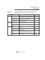
Section
Description
CONNECTIVITY GUIDELINES
Getting Started
Shows steps to get started and how to contact Agilent
Connecting Instruments to LANs
Gives guidelines to connect instruments to LANs
Connecting Instruments to USB
Gives guidelines to connect instruments to USB
Connecting Instruments to GPIB
Gives guidelines to connect instruments to GPIB
Programming Your Instruments
Gives guidelines to program instruments via LAN/USB/GPIB
REFERENCE INFORMATION
Installing I/O Software
Shows how to install I/O software on your PC
Troubleshooting Guidelines
Troubleshooting guidelines for LAN, USB, and GPIB Interfaces
TCP/IP Network Basics
Provides an overview of TCP/IP networks
Guide Information
Lists general information for this guide
Glossary
Defines some of the terms used in this guide
Index
Index of selected items in this guide
NOTE
Use the arrows next to each page number to navigate in this guide.
Click to return to
previous topic
Click to go to
previous page
Click to go to
next page
16
8
Getting Started
Steps to Get Started
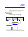
Steps to Get Started
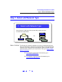
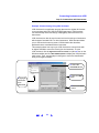
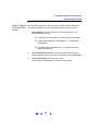
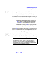
This figure shows suggested steps to get started setting up LAN, USB, or
GPIB interfaces and the applicable sections of this guide. Some guidelines
follow this figure to select the interface you want to set up.
CONNECTIVITY GUIDELINES
Start
LAN
Connect Instruments to LAN
" Select Your LAN Network
" Configure Instruments
" Communicate via LAN
See Connecting Instruments
to LANs
USB
Connect Instruments to USB
" Configure USB Network
" Communicate via USB
See Connecting Instruments
to USB
GPIB
Connect Instruments to GPIB
" Configure GPIB Network
" Communicate via GPIB
See Connecting Instruments
to GPIB
Program Your Instruments
" Using IVI-COM
" Using VXIpnp
" Using VISA
See Programming Your Instruments
REFERENCE INFORMATION
Troubleshooting Guidelines
" Troubleshooting LANs
" Troubleshooting USB
" Troubleshooting GPIB
See Troubleshooting Guidelines
TCP/IP Network Basics
" TCP/IP Protocol
" IP Addressing
" Network Services
See TCP/IP Network Basics
9
Guide Information
" Guide Contents
" Accessing Electronic Copy
" General Information
See Guide Information
Getting Started
Steps to Get Started
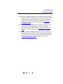
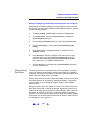
! Connect Instruments to LAN. A Local Area Network (LAN) provides
instrument connectivity over distances and allows sequential sharing
of instruments among multiple PCs. A LAN is the recommended
method to connect instruments together in applications such as new
test systems. If you select LAN connections, go to Connecting
Instruments to LANs.
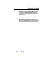
! Connect Instruments to USB. Universal Serial Bus (USB) is a quick
and easy way to connect instruments to PCs on a benchtop.
Typically, you can use USB to connect a single instrument to a PC.
If you select USB connections, go to Connecting Instruments to
USB.
! Connect Instruments to GPIB. The General Purpose Interface Bus
(GPIB) should be used only in a system that is already using GPIB
to connect instruments. GPIB is not recommended for applications
such as new systems. If you select GPIB connections, go to
Connecting Instruments to GPIB.
10
Connecting Instruments to LANs
! LAN Quick Start
!
!
!
!
Step 1: Select LAN Network Type
Step 2: Gather Network Information
Step 3: Connect Your Instruments
Step 4: Install I/O Software on Your PC
!
!
!
!
Step 5: Configure Your Instruments
Step 6: Configure the LAN Interface
Step 7: Communicate with Instruments
Step 8: Program Your Instruments
11
Connecting Instruments to LAN
LAN Quick Start
LAN Quick Start
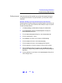
This section shows suggested steps to help you quickly get started
connecting and configuring your LAN-enabled instruments for site LAN or
private LAN operation.
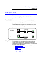
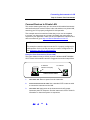
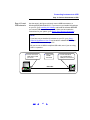
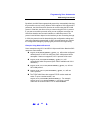
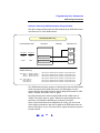
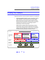
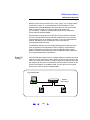
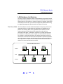
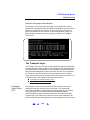
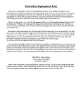
What are Site LANs A site LAN network is defined as a local area network (LAN) in which
and Private LANs? LAN-enabled instruments and Windows 98/2000/NT 4.0/Me/XP PCs are
connected to a site LAN (workgroup LAN, Intranet, or enterprise LAN) via
(optional) routers, hubs, and/or switches.
A private LAN network is defined as a local area network (LAN) in which
LAN-enabled instruments and Windows 98/2000/NT 4.0/Me/XP PCs are
NOT connected to a site LAN. This figure shows example site LAN and
private LAN networks.
To Site LAN
Typical Site LAN
PC
Instrument
Typical Private LAN
Ethernet Hub
or Switch
PC
Getting Started
Instrument
To get started, you may want to copy the following overview of steps to use
as a guide as you set up your instruments for site LAN or private LAN
operation. See the associated step if you need any more information.
See these sections for additional information on setting up your instruments
for site LAN or private LAN operation:
!
!
!
!
TCP/IP Network Basics for an introduction to TCP/IP networks
Troubleshooting LAN Interfaces for LAN troubleshooting tips
Glossary for a definition of some LAN terms
Contacting Agilent if you need to contact Agilent
12
Connecting Instruments to LAN
LAN Quick Start
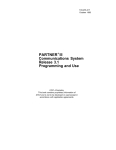
1 Select LAN Network Type
Select the type of LAN (site LAN or private LAN) to which you want
to connect your instruments.
Computer
Site
LAN
Computer
OR
Private LAN
Instrument
Instrument
Instrument
Instrument
2 Gather Network Information
Gather network parameters for site LAN connections or define private
LAN parameters.
Site LAN Network Information Card
lnstrument Information (Completed by Instrument User)
(Serial Number and Ethernet (MAC) Hardware Address usually on label on instrument)
Instrument Serial Number:
Ethernet (MAC) Hardware Address:
______________________________
______________________________
3 Connect Your Instruments
Connect your instruments to the site LAN or private LAN you selected.
To Site LAN
PC
Instrument
4 Install I/O Software on Your PC
Select the I/O software to be installed on your PC. Then, install the software
from a CD or from the W eb.
PC
13
Connecting Instruments to LAN
LAN Quick Start
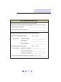
5 Configure Your Instruments
As required, manually configure your instruments using the instrument's
Web Pages or front panel.
You can use the Configuring
Your Instrument Web Page to
configure instruments.
6 Configure the LAN Interface
Use IO Config to configure the TCPIP LAN Client interface. Then, add
your instrument identifiers to the interface software.
The TCPIP Devices dialog
box lists devices present
on the interface.
7 Communicate with Instruments
You can use applications such as VISA Assistant or the Telnet utility to
verify communication with instruments via the LAN.
You can use VISA Assistant
to verify communication with
instruments.
8 Program Your Instruments
This is an optional step. As desired, you can program instruments via
the LAN using applications such as IVI-COM, VXIpnp, or VISA.
VISA: viOpen (..."TCPIP0::instrumentHostName::INSTR"...)
14
Connecting Instruments to LAN
Step 1: Select LAN Network Type
Step 1: Select LAN Network Type
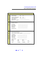
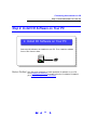
1 Select LAN Network Type
Select the type of LAN (site LAN or private LAN) to which you want
to connect your instruments.
Computer
Site LAN
OR
Computer
Instrument
Private LAN
Instrument
Instrument
Instrument
What’s in This Step? The first step is to determine whether you want your instruments and your
PC to be connected to a site LAN or to a private LAN. This step shows some
examples of site LAN and private LAN networks. Select site LAN or private
LAN connections, based on your requirements. Then, go to Step 2: Gather
Network Information.
# For examples of typical site LAN networks, go to
Typical Site LAN Networks
# For examples of typical private LAN networks, go to
Typical Private LAN Networks
15
Connecting Instruments to LAN
Step 1: Select LAN Network Type
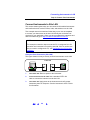
Typical Site LAN Networks
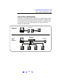
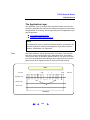
In this guide, a site LAN network is defined as a local area network (LAN) in
which LAN-enabled instruments and Windows 98/2000/NT 4.0/Me/XP PCs
are connected to a site LAN (workgroup LAN, Intranet, or enterprise LAN)
via (optional) routers, hubs, and/or switches. This figure shows some
example site LAN networks.
To Site LAN
Example Direct
Connection
Instrument
PC
Ethernet Hub
or Switch
To Site LAN
Example
Switch
Connection
PC
Instrument
Instrument
16
Instrument
Instrument
Connecting Instruments to LAN
Step 1: Select LAN Network Type
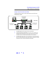
Typical Private LAN Networks
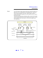
In this guide, a private LAN network is defined as a local area network (LAN)
in which LAN-enabled instruments and Windows 98/2000/NT 4.0/Me/XP
PCs are NOT connected to a site LAN (workgroup LAN, Intranet, or
enterprise LAN). This figure shows some example private LAN networks.
NOTE
For a private LAN you, the designer of the LAN, are the “System
Administrator” for the LAN and are responsible for defining all private
LAN parameters.
Example
Direct
Connection
CAT5 Crossover Cable
PC
Instrument
Ethernet Hub or Switch
Example
Switch
Connection
PC
Instrument
Instrument
17
Instrument
Instrument
Connecting Instruments to LAN
Step 2: Gather Network Information
Step 2: Gather Network Information
2 Gather Network Information
Gather network parameters for site LAN connections or define private
LAN parameters.
Site LAN Network Information Card
lnstrument Information (Completed by Instrument User)
(Serial Number and Ethernet (MAC) Hardware Address usually on label on instrument)
Instrument Serial Number:
______________________________
Ethernet (MAC) Hardware Address: ______________________________
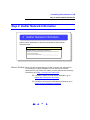
What’s in This Step? When you have selected the type of LAN to connect your instrument to,
the next step is to gather information for your site LAN or to define
parameters for your private LAN. When you have gathered the necessary
information, go to Step 3: Connect Your Instruments.
# For steps to gather site LAN network information, go to
Gather Site LAN Network Information.
# For steps to select private LAN network parameters, go to
Define Private LAN Network Parameters.
18
Connecting Instruments to LAN
Step 2: Gather Network Information
Gather Site LAN Network Information
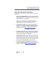
Suggested steps follow to gather information for instrument connections
to a site LAN.
1
Does the Site LAN Support DHCP? Find out if the site LAN supports
Dynamic Host Configuration Protocol (DHCP). In general, if the site
LAN supports DHCP, you can connect your instruments to site LAN
without contacting your IT department.
However, if your local policy requires it, contact your System
Administrator in your Information Technology (IT) department and
tell him/her you want to connect instruments to the LAN.
2
Select Automatic Configuration. If the site LAN supports DHCP,
IP addresses for the instruments are automatically assigned by the
network. If you do not require fixed (static) IP addresses for your
instruments, you do not need to complete the Site LAN Network
Information Card. Go to Step 3: Connect Your Instruments.
OR
2
Select Manual Configuration. If the site LAN does not support DHCP
or if you want to set a fixed (static) IP address for each instrument,
the System Administrator must assign the static IP addresses and
you must manually configure your instruments.
3
Enter Instrument Information. If the LAN does not support DHCP or
if you selected manual configuration, make a copy of the Site LAN
Network Information Card for each instrument to be connected to the
site LAN. Record the instrument serial number and hardware (MAC)
address on the Instrument Information section of the card.
4
Give the Cards to the System Administrator. Give the partially
completed card(s) to the System Administrator and ask him/her to
complete the Site LAN Information part of each card and to return the
card(s) to you. Then, go to Step 3: Connect Your Instruments.
19
Connecting Instruments to LAN
Step 2: Gather Network Information
Site LAN Network Information Card
lnstrument Information (Completed by Instrument User)
(Serial Number and Ethernet (MAC) Hardware Address usually on label on instrument)
Instrument Serial Number:
______________________________
Ethernet (MAC) Hardware Address: ______________________________
Site LAN Information (Completed by System Administrator)
Does the Network Support DHCP?
If No, provide:
Yes ___ No ___
IP Address (Static):
______.______.______._____
Subnet Mask:
______.______.______._____
Default Gateway:
______.______.______._____
Does the Network Support DNS?
If Yes, provide:
Yes ___ No ____
Instrument Host Name:
_______________________
Instrument Domain Name: _______________________
DNS Server IP Address:______.______.______._____
Will You Allow Universal Plug&Play to be Enabled? Yes ___ No ____
20
Connecting Instruments to LAN
Step 2: Gather Network Information
Define Private LAN Network Parameters
Suggested steps follow to define parameters for a private LAN.
NOTE
For a private LAN you, the designer of the LAN, are the “System
Administrator” for the LAN and are responsible for defining all private
LAN parameters. However, you may want to check with the System
Administrator in your Information Technology (IT) department for
guidelines on designing your private LAN.
1
Does the LAN Support DHCP? In general, private LANs with a router
support DHCP but typically do not support Dynamic DNS. Determine
if the LAN supports DHCP.
NOTE
Most Agilent products and PCs will automatically choose an IP address
via auto-IP if a DHCP server is not present.
2
Complete the Network Information Card. Make a separate copy of the
Private LAN Network Information Card for each instrument to be
connected to the private LAN. For each card, define and record
the network, PC settings, and instrument settings you want for the
LAN. As required, see TCP/IP Network Basics or the Glossary for a
definition of terms.
3
Where to go Next. When you have completed the Private LAN Network
Information Cards, go to Step 3: Connect Your Instruments.
21
Connecting Instruments to LAN
Step 2: Gather Network Information
Private LAN Network Information Card
N
E
T
W
O
R
K
DHCP Enabled:
Yes ___ No ____
Dynamic DNS Enabled:
Yes ___ No ____
UPnP Enabled OK:
Yes ___ No ____
Subnet Mask:
______.______.______._____
DNS Server IP Address: ______.______.______._____
Hardware Address: ________________________
P
C
I
N
S
T
R
U
M
E
N
T
IP Address:
______.______.______._____
Subnet Mask:
______.______._____.______
DNS Server:
______.______._____.______
Host Name:
________________________
Domain Name:
________________________
Instrument Serial Number:
_________________________
Ethernet (MAC) Hardware Address: ___________________
IP Address:
______.______.______._____
Subnet Mask:
DNS Server:
______.______._____.______
______.______._____.______
Host Name:
________________________
Domain Name:
________________________
DHCP:
ON___
OFF___
Auto IP:
ON___
OFF___
N/A___
UPnP:
Enabled___
Disabled___
N/A___
22
Connecting Instruments to LAN
Step 3: Connect Your Instruments
Step 3: Connect Your Instruments
3 Connect Your Instruments
Connect your instruments to the site LAN or private LAN you selected.
To Site LAN
PC
Instrument
What’s in This Step? This section gives guidelines to connect your instruments and LAN interface
devices such as routers, hubs, or switches to site LANs or to private LANs.
# To connect instruments to a site LAN, go to
Connect Instruments to Site LAN.
# To connect instruments to a private LAN, go to
Connect Devices to Private LAN.
23
Connecting Instruments to LAN
Step 3: Connect Your Instruments
Connect Instruments to Site LAN
This section shows typical ways you can connect LAN-enabled instruments
and interface devices such as routers, hubs, and switches to a site LAN.
Two example network connections follow that you can use as templates
to connect your instruments to the site LAN. Modify the connections as
required for your application. When you have completed the instrument and
device connections, go to Step 4: Install I/O Software on Your PC.
NOTE
The example connection steps assume the PC is configured for LAN
operation and connected to an existing site LAN. If this is not the case
and you need to configure the PC, see Configuring Your PC for LAN
Operation.
Example: Direct Connection (Site LAN)
This figure shows one way to directly connect instruments to a site LAN.
To Site LAN
Instrument
PC
1
Turn Power OFF. Remove power to the instrument.
2
Connect Instrument to the LAN. Use a standard CAT5 LAN
cable to connect the instrument to the site LAN.
3
Turn Power ON. Apply power to the instrument and verify proper
instrument power-on sequence. See the instrument’s User’s Guide
for information.
24
Connecting Instruments to LAN
Step 3: Connect Your Instruments
Example: Switch Connections (Site LAN)
This figure shows one way to connect instruments to a site LAN via an
Ethernet Hub or Switch.
Ethernet Hub
or Switch
To Site LAN
PC
Standard CAT5
LAN Cable
To LAN Port on
Instruments
Instrument
Instrument
Instrument
Instrument
1
Turn Power OFF. Remove power from the instruments.
2
Connect Instruments to Hub/Switch. If you use a hub or switch, use
standard CAT5 LAN cables to connect each instrument to the hub
or switch. See the hub/switch documentation for connections.
3
Turn Power ON. Apply power to the hub/switch (if not already ON) and
then to the instruments and verify proper power-on sequence. See the
instrument’s User’s Guide for instrument information.
25
Connecting Instruments to LAN
Step 3: Connect Your Instruments
Connect Devices to Private LAN
This section shows typical ways you can connect LAN-enabled instruments
and interface devices such as routers, hubs, and switches to a private LAN,
assuming your PC is properly configured for LAN operation.
Two example network connections follow that you can use as templates
to connect your instruments to a private LAN. Modify the connections as
required for your application. When you have completed the instrument and
device connections, go to Step 4: Install I/O Software on Your PC.
NOTE
The example connection steps assume the PC is properly configured for
LAN operation. If this is not the case and you need to configure the PC,
see Configuring Your PC for LAN Operation.
Example: Direct Connections (Private LAN)
This figure shows one way to directly connect a Windows 98/NT/2000/Me/
XP PC with a LAN-enabled instrument. Suggested connection steps follow.
To Network
Interface Card (NIC)
To LAN Port
CAT5 Crossover Cable
PC
Instrument
1
Turn Power OFF. Remove power from the instrument.
2
Connect Instrument to the LAN. Use a standard CAT5 crossover cable
to connect the instrument to the LAN.
3
Turn Power ON. Apply power to the instrument and verify proper
instrument power-on sequence. See the instrument’s User’s Guide for
information on instrument power-on sequences.
26
Connecting Instruments to LAN
Step 3: Connect Your Instruments
Example: Switch Connections (Private LAN)
This figure shows one way to connect a Windows 98/NT/2000/Me/XP PC
and LAN-enabled instruments via an Ethernet hub or switch. Suggested
connection steps follow.
See hub/switch
documentation
for connections
To Network Interface
Card (NIC)
Ethernet Hub
or Switch
PC
Standard CAT5
LAN Cable
To LAN Port on
Instruments
Instrument
Instrument
Instrument
Instrument
1
Turn Power OFF. Remove power to instruments and the hub/switch.
2
Connect Instruments to Hub or Switch. Use standard CAT5 LAN cables
to connect each instrument to the hub or switch. See the hub or switch
documentation for connection information.
3
Turn Power ON. Apply power to the hub/switch (if not already ON) and
then to the instruments and verify proper power-on sequence. See the
instrument’s User’s Guide for information on instrument power-on
sequences.
27
Connecting Instruments to LAN
Step 4: Install I/O Software on Your PC
Step 4: Install I/O Software on Your PC
4 Install I/O Software on Your PC
Select the I/O software to be installed on your PC. Then, install the software
from a CD or from the Web.
PC
What’s in This Step? This step gives guidelines to install applicable I/O software on your PC.
Go to Installing I/O Software for details. After the I/O software is installed,
go to Step 5: Configure Your Instruments.
28
Connecting Instruments to LAN
Step 5: Configure Your Instruments
Step 5: Configure Your Instruments
5 Configure Your Instruments
As required, manually configure your instruments using the instrument's
Web Pages or front panel.
You can use the Configuring
Your Instrument Web Page to
configure instruments.
What’s in This Step? This may be an optional step. This step shows how to manually set
TCP/IP parameters for LAN-enabled instruments, using the instrument’s
Web Pages.
# If your LAN supports DHCP and you selected automatic
configuration for your instruments, skip this step and go to
Step 6: Configure the LAN Interface.
# If the LAN does not support DHCP or you want to make
configuration changes, you can use the steps in this section
to configure your instruments. Then, go to Step 6: Configure
the LAN Interface.
29
Connecting Instruments to LAN
Step 5: Configure Your Instruments
Check Your Web Browser
If your instrument is Web-enabled, the instrument includes a Web Server
you can access using a supported Web Browser (Internet Explorer 5.0 or
higher). You can then use your Web Browser and the instrument’s Web
Pages to view/modify network configuration parameters as required.
NOTE
If your instrument is not Web-enabled or you cannot access the
instrument at its IP address, you must set the TCP/IP parameters from
the instrument’s front panel.
Set/Change TCP/IP Parameters
1
Display the Instrument Welcome Page. To display an instrument’s
Welcome Page, determine the instrument’s IP address from the front
panel display. Then, open your Web Browser. From the Web Browser
address line, type ‘http://<Instrument IP Address>’, where <Instrument
IP Address> is the IP address displayed on the front panel, and press
Enter to display the instrument’s Welcome Page.
For example, if the instrument’s current IP address is 169.254.3.2
(as displayed on the instrument’s front panel), typing http://169.254.3.2
and pressing Enter displays the instrument’s Welcome Page. This figure
shows a typical display for the Agilent 33220A.
30
Connecting Instruments to LAN
Step 5: Configure Your Instruments
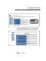
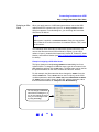
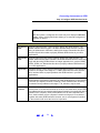
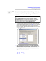
2
View Current Configuration Page. To view the current configuration,
click the View and Modify Configuration icon to display the Current
Configuration Page. An example display for the 33220A follows.
31
Connecting Instruments to LAN
Step 5: Configure Your Instruments
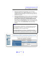
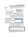
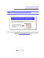
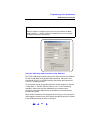
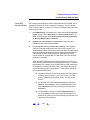
3
Display the Configuring the Instrument Page. From the Current
Configuration Page, click the Modify Configuration box to display the
Configuring the Instrument Page. You can then set/change instrument
parameters as required
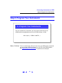
4
Set/Change TCP/IP Parameters. This figure shows a partial Configuring
your 20MHz Function/Arbitrary Waveform Generator Page. For example,
we will change the settings for the 33220A IP address, and default
gateway from the values shown in the Configured Value column to
those shown in the Edit Configuration column. To do this, we type the
desired values in the Edit Configuration column and click Save to save
the values. Then, we click Reboot 33220A to make the changes
effective.
NOTE
Since the IP Address, Subnet Mask, and Default Gateway parameters
are marked with an asterisk (*), you must click Save and then click
Reboot 33220A to make the changes effective.
The Configured Value for the IP Address, Subnet Mask and Default
Gateway are NOT necessarily the values currently set for the instrument.
These values will be used during boot if DHCP is OFF or is unavailable.
32
Connecting Instruments to LAN
Step 6: Configure the LAN Interface
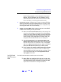
Step 6: Configure the LAN Interface
6 Configure the LAN Interface
Use IO Config to configure the TCPIP LAN Client interface. Then, add
your instrument identifiers to the interface software.
The TCPIP Devices dialog
box lists devices present
on the interface.
What’s in This Step? This step gives guidelines to use the IO Config utility (installed as part of
the Agilent IO Libraries) to configure the LAN interface.
33
Connecting Instruments to LAN
Step 6: Configure the LAN Interface
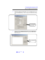
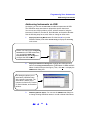
Steps to Configure
the LAN Interface
For an application that uses VISA (such as VISA Assistant) to communicate
with instruments via the LAN, you must configure the TCPIP LAN Client
interface by using the IO Config utility. Suggested steps to configure the
TCPIP LAN Client interface follow.
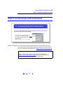
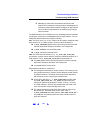
1
Open the IO Config Utility. To configure a TCPIP LAN Client interface,
click the Agilent IO Libraries Control icon (blue IO icon on the Windows
taskbar) and click Run IO Config to display the IO Config main screen.
The I/O Config main screen allows
you to select and configure ASRL
(Serial), GPIB, TCP/IP, USB, and
VXI interfaces.
For this example, we will configure
TCP/IP interfaces.
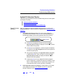
2
Display the TCPIP LAN Client Dialog Box. From the main screen,
highlight the TCPIP LAN Client (LAN Instruments) menu item and
then click Configure to display the LAN Client dialog box.
Highlight TCPIP
LAN Client
Click Configure
34
Connecting Instruments to LAN
Step 6: Configure the LAN Interface
3
Set LAN Client Parameters. When the LAN Client dialog box appears, in
almost all cases, you can accept the default settings. If you need to
change any items, click the Help button for an explanation of the items.
Change items as required and then click the OK button to re-display
the IO Config main screen.
Click OK
Typically, you
can accept the
default settings.
4
Re-Display LAN Client Dialog Box. When the IO Config main screen
reappears, in the Configured Interfaces box highlight the TCP/IP device
name you set in the previous step (VISA Interface Name of TCPIP0
and SICL Interface Name of lan in this example). Then, click the Edit...
button to re-display the LAN Client dialog box.
Highlight TCP/IP
Device Name
Click Edit...
35
Connecting Instruments to LAN
Step 6: Configure the LAN Interface
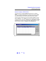
5
Display the TCPIP Devices Dialog Box. From the LAN Client dialog box,
click the Edit VISA Config... button to display the TCPIP devices dialog
box.
Click the Edit VISA
Config... button
6
Display the Add a TCPIP device Dialog Box. From the TCPIP devices
dialog box, click the Add device button to display the Add a TCPIP
device dialog box.
Click the Add device
button
36
Connecting Instruments to LAN
Step 6: Configure the LAN Interface
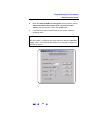
7
Enter Device IP Address/Hostname. From the Add a TCPIP device dialog
box, enter either the IP address or hostname of the LAN instrument to
be added and then click the OK button to re-display the TCPIP devices
dialog box. For example, this dialog box adds a TCP/IP device at IP
address 156.140.105.104.
Click OK
Enter IP Address
8
Display Devices Present. The TCPIP devices dialog box displays the
TCP/IP devices present on the network. For example, this dialog box
shows a device with identifier TCPIP0::156.140.105.104::inst0::INSTR
is present on the network. Click the OK button to close this dialog box.
Then, click the OK button on each open dialog box to close the box.
9
Repeat for Other Instruments. If you have more than one instrument to
be added to the network, repeat the previous steps for each instrument
to be added. Then, go to Step 7: Communicate with Instruments.
37
Connecting Instruments to LAN
Step 7: Communicate with Instruments
Step 7: Communicate with Instruments
7 Communicate with Instruments
You can use applications such as VISA Assistant or the Telnet utility to
verify communication with instruments via the LAN.
You can use VISA Assistant
to verify communication with
instruments.
What’s in This Step? This section gives guidelines to communicate with your instruments using
VISA Assistant. When you have verified communication with your
instruments (as desired), go to Step 8: Program Your Instruments.
NOTE
Communication with installed LAN instruments was established in
Step 6: Configure the LAN Interface if the instrument(s) were displayed
in the TCPIP devices dialog box. Thus, this is an optional step you can use
to verify communication with instruments.
38
Connecting Instruments to LAN
Step 7: Communicate with Instruments
Communicating Using VISA Assistant
VISA Assistant is an application program that uses the Agilent IO Libraries
to communicate with LAN, USB, and GPIB instruments. VISA Assistant
can automatically detect and assign VXIplug&play instrument drivers to
instruments.
VISA Assistant can also be used to send and receive strings to instruments
which support formatted I/O. For other instruments, VISA Assistant allows
you to read and write memory areas. An example follows to show one way
to communicate with a 33220A using VISA Assistant.
Example: Communicating Using VISA Assistant
This example shows one way to use VISA Assistant to communicate with
an Agilent 33220A to return the ID string for the instrument. To open
VISA Assistant, click the Agilent IO Libraries Control icon (blue icon on the
Windows taskbar) and click Run VISA Assistant to display the VISA Assistant
main screen. Then, use the steps in this figure to return the identification
string for an Agilent 33220A.
2 Select the
Formatted I/O tab
1 Highlight
instrument
to be
addressed
4 Click the *IDN?
button
3 Select the SCPI
button
39
Connecting Instruments to LAN
Step 8: Program Your Instruments
Step 8: Program Your Instruments
8 Program Your Instruments
This is an optional step. As desired, you can program instruments via the
LAN using applications such as IVI-COM, VXIpnp, or VISA.
VISA: viOpen (..."TCPIP0::instrumentHostName::INSTR"...)
What’s in This Step? This is an optional step. After you have set up your site or private LAN,
as desired you can program LAN-enabled instruments from your PC via the
LAN. See Programming Your Instruments for guidelines and examples.
40
Connecting Instruments to USB
! USB Quick Start
! Step 1: Install I/O Software on Your PC
! Step 2: Connect Instruments to USB
! Step 3: Assign Instrument Alias Name
! Step 4: Check Instrument Identification
! Step 5: Communicate with Instruments
! Step 6: Program Your Instruments
41
Connecting Instruments to USB
USB Quick Start
USB Quick Start
This section shows suggested steps to help you quickly get started
connecting USB-enabled instruments to the Universal Serial Bus (USB).
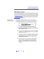
NOTE
Optionally, a USB hub may be connected between the PC and USB
instrument(s). However, this configuration is not described in this guide.
See your USB hub documentation if you use a USB hub.
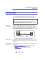
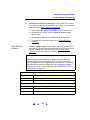
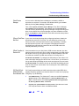
Typical USB
Interface System
In this guide, a USB interface system is defined as a system in which
USB-enabled instruments are connected via a USB cable to a USB 1.1 port
in a Windows 98 (SE)/Me/2000/XP PC or to a USB 2.0 port in a Windows XP
(with Service Pack 1) PC. This figure shows a typical USB interface system
with a PC and a USB instrument connected via a USB cable.
USB Cable
PC
Connect to USB
port on PC.
Connect to
USB port on
instrument.
Instrument
Getting Started
To get started, you may want to copy the figures for Steps 1 - 6 to use as a
guide as you set up your USB system. See the associated step if you need
more details.
Other Information
You Can Use
See these sections for additional information on setting up instruments for
USB operation:
! Troubleshooting USB Interfaces for USB troubleshooting tips
! Glossary for a definition of some USB terms
! Contacting Agilent if you need to contact Agilent
42
Connecting Instruments to USB
USB Quick Start
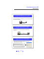
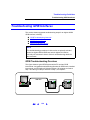
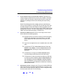
1 Install I/O Software on Your PC
Select the I/O software to be installed on your PC. Then, install the software
from a CD or from the Web.
PC
2 Connect Instruments to USB
Use USB cables to connect your instruments to the USB port(s)
on your PC.
USB Cable
PC
Instrument
3 Assign Instrument Alias Name
As desired, assign each instrument's USB Alias name from the
Assign USB device alias dialog box.
We recommend you choose a unique,
meaningful USB Alias name and enter it in this
dialog box. (If you do not assign the name
now, you can change it later using IO Config.)
43
Connecting Instruments to USB
USB Quick Start
4 Check Instrument Identification
As desired, use IO Config to display the USB Devices dialog box. From
this dialog box, you can check instrument identification parameters.
This dialog box associates an
instrument's USB Alias name with
the instrument's Serial number,
Vendor ID, Product ID, and
Product Identification.
5 Communicate with Instruments
You can use applications such as VISA Assistant to verify communication
with instruments via the USB interface.
You can use VISA Assistant
to verify communication with
instruments.
6 Program Your Instruments
This is an optional step. As desired, you can program instruments via the
USB interface using applications such as IVI-COM, VXIpnp, or VISA.
VISA: viOpen (...,"ArbGen",...)
SICL: iopen ("ArbGen")
44
Connecting Instruments to USB
Step 1: Install I/O Software on Your PC
Step 1: Install I/O Software on Your PC
1 Install I/O Software on Your PC
Select the I/O software to be installed on your PC. Then, install the software
from a CD or from the Web.
PC
What’s in This Step? As required, you should install I/O software (such as the Agilent IO
Libraries), on your PC before you connect instruments to USB. See
Installing I/O Software for details. Then, go to Step 2: Connect Instruments
to USB.
NOTE
Version M.01.00 or later of the Agilent IO Libraries is required for USB.
45
Connecting Instruments to USB
Step 2: Connect Instruments to USB
Step 2: Connect Instruments to USB
2 Connect Instruments to USB
Use USB cables to connect your instruments to the USB port(s)
on your PC.
USB Cable
PC
Instrument
What’s in This Step? This step shows how to connect USB Instruments to USB ports on your PC.
46
Connecting Instruments to USB
Step 2: Connect Instruments to USB
Steps to Connect
USB Instruments
Use the steps in this figure to directly connect USB instruments to a
Windows 98(SE)/Me/2000/XP PC. If you have not yet installed I/O software
on your PC, go to Installing I/O Software and install the software BEFORE
you connect USB instruments to your PC. When you have made the
connections for your system, go to Step 3: Set Instrument Alias Name.
NOTE
If you have not yet installed I/O software on your PC, go to Step 1:
Install I/O Software on Your PC and install the software BEFORE you
connect USB instruments to your PC.
Be sure to use a USB 2.0-compliant USB cable, even if you are using
USB 1.1 operation.
b Apply power
to USB
instrument
a Connect PC end of
USB cable to USB
port on PC
c Connect instrument
end of USB cable to
USB port on instrument
USB Cable
PC
Instrument
47
Connecting Instruments to USB
Step 3: Assign Instrument Alias Name
Step 3: Assign Instrument Alias Name
3 Assign Instrument Alias Name
As desired, set/change each instrument's USB Alias name from the
Assign USB device alias dialog box.
We recommend you choose a unique,
meaningful USB Alias name and enter it in this
dialog box. (If you do not assign the name
now, you can change it later using IO Config.)
What’s in This Step? This step shows how to assign an Alias name for USB instruments. You can
use the Alias name when addressing the instrument.
48
Connecting Instruments to USB
Step 3: Assign Instrument Alias Name
Assigning an Alias
Name
When you apply power to a USB instrument and then connect the USB
cable between the instrument and your PC, an Assign USB device alias
dialog box appears. From this dialog box, you can assign the instrument
Alias name, as desired.
NOTE
When power is applied, a Found New Hardware dialog box may appear.
If so, follow the on-screen instructions for installation advice. Then, return
to this section.
The USB Alias name associates an alias with a specific instrument. You
can use the Alias name as a VISA rsrcName in viOpen( ) or as a SICL
address in iopen( ) instead of the instrument’s Vendor ID, Product ID, Serial
Number, and Interface Number (see Step 4: Check Instrument Identification
for details).
Example: Assigning a USB Alias Name
This figure shows an example Assign USG device alias dialog box for an
Agilent 33220A. To change the USB Alias name, type the new name in the
Alias name box and then click the OK button. The Alias name can be used as
the preferred address for the VISA rsrcName and the SICL address.
For this example, the Alias name has been changed to .ArbGen. from the
default .UsbDevice1.. Thus, ArbGen can be used in viOpen() as the VISA
rsrcName parameter, rather than .USB0::2391::1031::MY43000029::0::INSTR..
Or, ArbGen can be used in iopen() as the SICL address parameter, rather
than the alternate address of .usb0[2391::1031::MY43000029::0].
You can assign a USB Alias
name from this dialog box. (If
you do not change the name
now, you can change it later
by using IO Config.)
49
Connecting Instruments to USB
Step 4: Check Instrument Identification
Step 4: Check Instrument Identification
4 Check Instrument Identification
As desired, use IO Config to display the USB Devices dialog box. From
this dialog box, you can check instrument identification parameters.
This dialog box associates an
instrument's USB Alias name with
the instrument's Serial number,
Vendor ID, Product ID, and
Product Identification.
What’s in This Step? This is an optional step that shows suggested steps follow to check
instrument identification parameters. If you do not want to check instrument
identification parameters, skip to Step 5: Communicate with Instruments.
50
Connecting Instruments to USB
Step 4: Check Instrument Identification
Steps to Check
Identification
Parameters
1
Display the IO Config Main Screen. Click the blue IO icon (on the
Windows Taskbar) and select Run IO Config to display the IO Config
main screen.
If there is no entry in the Configured
Interfaces box for USB instruments,
you can highlight USB *USB
Instruments and click Configure to
configure the USB interface.
2
Display the USB Devices Dialog Box. Highlight the USB instrument
name in the Configured Interfaces box (VISA Name of USB0 and SICL
Name of usb0 for the previous figure). Then, click Edit... to display the
USB Devices dialog box.
This dialog box allows you to
associate a USB Alias name
with a specific instrument. The
association is based on the
instrument’s Serial Number,
Vendor ID, Product ID, and
Product Identification.
3
Add/Change/Delete Aliases. You can use the USB Devices dialog box
to change existing USB Alias names or to add or delete Alias names.
Click the Add Alias box to display the Add Alias dialog box, click the
Edit Alias box to display the Assign USB device alias dialog box, or click
the Delete Alias box to delete the highlighted alias.
NOTE
! Multiple alias names may be associated with the same instrument.
! If you delete all aliases, you can restore a default alias by
closing IO Config and cycling power on the instrument.
51
Connecting Instruments to USB
Step 5: Communicate with Instruments
Step 5: Communicate with Instruments
5 Communicate with Instruments
You can use applications such as VISA Assistant to verify communication
with instruments via the USB interface.
You can use VISA Assistant
to verify communication with
instruments.
What’s in This Step? This is an optional step that gives guidelines to communicate with your
instruments using VISA Assistant. When you have verified communication
with your instruments (as desired), go to Step 6: Program Your Instruments.
NOTE
Communication with installed instruments was established in
Step 2: Connect Instruments to USB. Thus, this is an optional step
you can use to verify communication with instruments.
52
Connecting Instruments to USB
Step 5: Communicate with Instruments
Example: Communicating Using VISA Assistant
VISA Assistant is an application program that uses the Agilent IO Libraries
to communicate with LAN, USB, and GPIB instruments. VISA Assistant
can automatically detect and assign VXIplug&play instrument drivers to
instruments.
VISA Assistant can also be used to send and receive strings to instruments
which support formatted I/O. For other instruments, VISA Assistant allows
you to read and write memory areas. VISA Assistant also describes
attributes that are associated with an instrument.
This example shows one way to use VISA Assistant to communicate with
an Agilent 33220A to return the ID string for the instrument. To open
VISA Assistant, click the Agilent IO Libraries Control icon (blue IO icon on the
Windows taskbar) and click Run VISA Assistant to display the VISA Assistant
main screen. Then, use the steps in this figure to return the identification
string for an Agilent 33220A.
2 Select the
Formatted I/O tab
4 Click the *IDN?
button
1 Highlight
instrument
to be
addressed
3 Select the SCPI
button
53
Connecting Instruments to USB
Step 6: Program Your Instruments
Step 6: Program Your Instruments
6 Program Your Instruments
This is an optional step. As desired, you can program instruments via the
USB interface using applications such as IVI-COM, VXIpnp, or VISA.
VISA: viOpen (...,"ArbGen",...)
SICL: iopen ("ArbGen")
What’s in This Step? This is an optional step. After you have set up your USB system, as desired
you can program USB instruments from your PC via the USB interface. See
Programming Your Instruments for guidelines and examples.
54
Connecting Instruments to GPIB
! GPIB Quick Start
! Step 1: Install I/O Software on Your PC
! Step 2: Install GPIB Cards in Your PC
! Step 3: Connect Instruments to GPIB Card
! Step 4: Configure GPIB Interface Cards
! Step 5: Communicate with Instruments
! Step 6: Program Your Instruments
55
Connecting Instruments to GPIB
GPIB Quick Start
GPIB Quick Start
This section shows suggested steps to help you quickly get started
connecting GPIB instruments to the General Purpose Interface Bus (GPIB).
Typical GPIB
Interface System
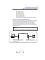
In this guide, a GPIB interface system is defined as a system in which GPIB
instruments are connected to a GPIB interface card in a Windows 98/2000/
NT 4.0/Me/XP PC via GPIB cables. This figure shows a typical GPIB
interface system with a PC and two GPIB Instruments connected via GPIB
cables.
GPIB Cable
Instrument
PC
Connect to GPIB Interface
Card installed in PC.
Instrument
Connect to GPIB
port on instrument.
Getting Started
To get started, you may want to copy the figures for Steps 1 - 6 to use as a
guide as you set up your GPIB system. See the associated step if you need
more details.
Other Information
You Can Use
See these sections for additional information on setting up instruments for
GPIB operation:
! Troubleshooting GPIB Interfaces for GPIB troubleshooting tips
! Glossary for a definition of some GPIB terms
! Contacting Agilent if you need to contact Agilent
56
Connecting Instruments to GPIB
GPIB Quick Start
1 Install I/O Software on Your PC
Select the I/O software to be installed on your PC. Then, install the software
from a CD or from the Web.
PC
2 Install GPIB Card(s) in Your PC
As required, install one or more GPIB Interface Cards in your PC.
3 Connect Instruments to GPIB Card
Connect your instruments to the installed GPIB Interface Card(s) using
GPIB cables.
GPIB Cable
Instrument
PC
57
Connecting Instruments to GPIB
GPIB Quick Start
4 Configure GPIB Interface Cards
Use IO Config to configure installed GPIB Interface Card(s) parameters.
You can use the GPIB Card
Configuration dialog box to
configure GPIB Interface
Cards installed in your PC.
5 Communicate with Instruments
You can use applications such as VISA Assistant to verify communication
with instruments via the GPIB interface.
You can use VISA Assistant
to verify communication with
instruments.
6 Program Your Instruments
This is an optional step. As desired, you can program instruments via the
GPIB interface using applications such as IVI-COM, VXIpnp, or VISA.
VISA: viopen (..."GPIB0::5::INSTR"...)
58
Connecting Instruments to GPIB
Step 1: Install I/O Software on Your PC
Step 1: Install I/O Software on Your PC
1 Install I/O Software on Your PC
Select the I/O software to be installed on your PC. Then, install the software
from a CD or from the Web.
PC
What’s in This Step? Before you connect your instruments to GPIB, as required install I/O
software, such as the Agilent IO Libraries, on your PC. See Installing I/O
Software for details. Then, go to Step 2: Install GPIB Cards in Your PC.
59
Connecting Instruments to GPIB
Step 2: Install GPIB Cards in Your PC
Step 2: Install GPIB Cards in Your PC
2 Install GPIB Cards in Your PC
As required, install one or more GPIB Interface Cards in your PC.
What’s in This Step? This step shows how to install GPIB Interface Cards (such as an Agilent
82350 PCI GPIB Interface for Windows) in your PC.
NOTE
If you have not yet installed I/O software on your PC, go to Step 1: Install
I/O Software on Your PC and install the software BEFORE you install
GPIB Interface Cards in your PC.
60
Connecting Instruments to GPIB
Step 2: Install GPIB Cards in Your PC
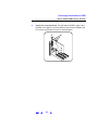
Steps to Install a
GPIB Card in Your
PC
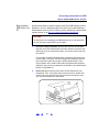
Example steps follow to install an Agilent 82350 PCI GPIB Interface Card for
Windows in your PC. Modify the steps as required if you install a different
GPIB Interface Card in your PC. When you have installed all required GPIB
Interface Cards, go to Step 3: Connect Instruments to GPIB Card.
CAUTION
To reduce the risk of damaging a GPIB Interface Card, only handle the
card by the sheet metal frame or by its edges.
1
Record the Card Serial Number. Remove the card from its anti-static
bag and record the Serial Number for future reference. Save the antistatic bag so you can protect the card if you need to remove the card
from the PC.
For example, the 82350 Serial Number is located on the white serial
number label on the card. The label contains 24 characters, with the
last 8 characters (plus US) being the 82350 Serial Number. Thus,
if the numbers on the serial number label are 82350-66511-4224-0142300113, since the last 8 characters are 42300113, the 82350 Serial
Number is US42300113.
2
Remove PC Cover. Remove power from the PC and from all of its
peripherals. Then, remove the power cord from the PC. Unlock and
remove the cover from the PC to allow access to the I/O slots. See
your PC documentation for instructions.
61
Connecting Instruments to GPIB
Step 2: Install GPIB Cards in Your PC
3
Remove a Cover Plate. Remove one of the PC back panel cover plates.
The 82350B is a 5V PCI card and will not fit in a 3.3V PCI slot or in an
EISA or ISA slot. Choose a 5V PCI slot that will give adequate
clearance for the GPIB connector.
4
Install the 82350. Insert the 82350 Interface Card edge connector into
the PCI expansion slot connector of the PC. Make sure the interface is
fully seated by pushing firmly on the top edge of the card with the palm
of your hand. The GPIB connector should extend through the back
panel opening to allow GPIB cable connection.
If you install more than one 82350, you may want to install the cards
so there is at least one empty slot between every two 82350s. When
inserting the 82350, be sure to hold the card by its edges. Also, be
careful with the metal faceplate around the GPIB connector as the
faceplate can be bent.
62
Connecting Instruments to GPIB
Step 2: Install GPIB Cards in Your PC
5
Replace the Cover Plate Screw. This will hold the 82350 in place. Save
the blank cover plate for use if the 82350 is later removed. Replace the
PC cover(s) as described in your PC documentation.
63
Connecting Instruments to GPIB
Step 3: Connect Instruments to GPIB Card
Step 3: Connect Instruments to GPIB Card
3 Connect Instruments to GPIB Card
Connect your instruments to the installed GPIB Interface Card(s) using
GPIB cables.
GPIB Cable
Instrument
PC
What’s in This Step? This step gives guidelines to connect GPIB instruments to a GPIB Interface
Card (such as an Agilent 82350) installed in your PC by using GPIB cables.
When you have made the connections for your system, go to
Step 4: Configure GPIB Interface Cards.
64
Connecting Instruments to GPIB
Step 3: Connect Instruments to GPIB Card
Steps to Connect
1
Instruments to GPIB
Cards
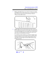
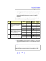
Review Connection Guidelines. The recommended method for
connecting a GPIB system is linear with the system controller (PC)
at one end of the system. However, a GPIB system can also be
connected together in a star, linear, or a combination configuration as
long as the total number of devices on the system is ≤15 and these
guidelines are followed:
# To minimize stress on connector mountings, no more than
three cable connectors blocks should be stacked on top of
one another. The GPIB connector screws should be fingertightened only.
# Minimize cable length as much as possible. All system
devices must have tri-state drivers and must be powered on.
Systems with devices not using tri-state drivers are limited to
transfer rates <250 Kbytes/sec. Turning devices on or off
while a system is running may cause faulty operation.
# For operation with data transfer rates <500 Kbytes/sec, the
total length of all GPIB cables is ≤2 meters times the number
of devices connected together, up to a maximum of 20
meters.
# For operation with data transfer rates > 500 Kbytes/sec, the
total length of all GPIB cables is ≤1 meter times the number
of devices connected together, up to a maximum of 15
meters.
# The length between adjacent devices is not critical as long as
the overall restriction is met. GPIB bus extenders are
available that allow operation over much greater distances.
2
Connect GPIB Cables to the GPIB Interface Card. Connect a separate
GPIB cable to each installed GPIB Interface Card using one of the
following cables. Tighten the GPIB connector screws finger-tight only.
(The screwdriver slots are for removal purposes only.) Two example
connections follow connect a single GPIB instrument or to connect
multiple GPIB instruments.
65
Connecting Instruments to GPIB
Step 3: Connect Instruments to GPIB Card
#
#
#
#
#
#
#
10833A (1 meter)
10833B (2 meters)
10833C (4 meters)
10833D (0.5 meter)
8120-3448 (6 meters)
8120-3449 (8 meters)
Other IEEE-488 GPIB interface bus cables, as applicable
Example: Connecting a Single GPIB Instrument
This figure shows connections from a single GPIB instrument to the GPIB
connector of an Agilent 82350 GPIB Interface Card installed in your PC.
You may want to record the primary GPIB address of the attached
instrument for future programming use. After making the connections,
reconnect the PC power cord and apply power to the PC and to attached
peripherals/instruments. .
CAUTION
To avoid damage to the connectors, only finger-tighten the connectors.
GPIB Cable
Instrument
PC
GPIB Connector. Connect to GPIB
connector on 82350 GPIB Interface
Card installed in PC.
66
GPIB Connector. Connect to
GPIB port on GPIB Instrument.
Connecting Instruments to GPIB
Step 3: Connect Instruments to GPIB Card
Example: Connecting Multiple GPIB Instruments
This figure shows one way to connect three GPIB instruments to an Agilent
82350 GPIB Interface Card. You may want to record the primary GPIB
address of each attached instrument for future programming use. After
making the connections, reconnect the PC power cord and apply power to
the PC and attached peripherals/instruments.
CAUTION
To avoid damage to the connectors, only finger-tighten the connectors.
NOTE
Although the figure shows cable connections to GPIB Instrument 1,
the connection can be to any GPIB instrument in the system.
GPIB Connector. Connect to GPIB
connector on 82350 Interface Card.
GPIB Connector.
Connect to GPIB port
on GPIB Instrument 1.
GPIB Cable
PC
Instrument 1
Instrument 2
Instrument 3
67
Connecting Instruments to GPIB
Step 4: Configure GPIB Interface Cards
Step 4: Configure GPIB Interface Cards
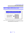
4 Configure GPIB Interface Cards
Use IO Config to configure installed GPIB Interface Card(s) parameters.
You can use the GPIB Card
Configuration dialog box to
configure GPIB Interface
Cards installed in your PC.
What’s in This Step? This step shows suggested actions to use the IO Config utility to configure a
Windows 98/Me/2000/NT/XP operating system for a PC that has an Agilent
82350 GPIB Interface Card (or equivalent) installed.
68
Connecting Instruments to GPIB
Step 4: Configure GPIB Interface Cards
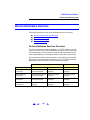
Steps to Configure
GPIB Interface
Cards
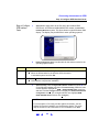
1
Apply Power. Apply power to the PC and to the installed GPIB
instruments. As Windows 98/Me/2000/NT/XP restarts, a Found New
Hardware Wizard may start. This figure shows a typical Windows 2000
display. The display may be different for other operating systems.
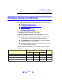
2
Install Configuration Files. Use this table for the actions to take for the
operating systems listed.
OS
98/Me
Action
! When the Wizard asks for the Agilent IO Libraries CD, click OK.
! When the Wizard asks for the hpioclas.dll file, browse to
C:\windows\system\ and click OK.
2000/XP
! Click Next> to accept the default suggestions.
! Click Finish to complete the installation.
3
Open IO Config. Click the Agilent IO Libraries Control icon (blue IO icon
on the Windows taskbar) and then click Run IO Config. When the main
screen appears, highlight the GPIB 82350 PCI GPIB Card menu item
and then click the Configure button to display the 82350 PCI GPIB Card
Configuration screen. (For an Agilent 82341 card, highlight GPIB
82341 ISA GPIB Card and then click Configure).
NOTE
For a description of IO Config and the Agilent IO Libraries, see the
Agilent IO Libraries Installation and Configuration Guide. This guide
may be included on the instrument CD or is available on the Web.
69
Connecting Instruments to GPIB
Step 4: Configure GPIB Interface Cards
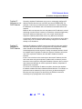
4
Configure GPIB Card Parameters. When the 82350 PCI GPIB Card
Configuration screen appears, set the VISA Interface Name, SICL
Interface Name, Logical Unit and Bus Address values as required.
Also, verify that this is the System Controller for the GPIB to which it
is attached (this is the typical operating mode). (See the System
Controller discussion.) Then, click the OK button. Some guidelines
to set these values follow.
70
Connecting Instruments to GPIB
Step 4: Configure GPIB Interface Cards
NOTE
After the system is configured, this screen may also display an Edit VISA
Config... button. Clicking this button allows you to manually configure the
interface as desired.
82350 GPIB Interface Card Configuration Parameters
SICL Interface
Name
Symbolic name that SICL uses to uniquely identify this GPIB interface. The
default Interface Name is gpib0. The SICL Interface Name must be a unique
string of alphanumeric characters, starting with a letter. Remember this value
and the Logical Unit number to properly address GPIB devices in your SICL
applications.
VISA Interface Symbolic name that VISA uses to uniquely identify this GPIB interface. The
Name
default VISA Interface Name is GPIB0. The 82350 Interface Name for VISA must
begin with the string GPIB and have an integer appended to it, such as GPIB0,
GPIB1, GPIB2, etc. Remember this value to properly address GPIB devices in
your VISA applications.
Logical Unit
Number that SICL uses to uniquely identify this 82350 interface. The Logical Unit
number is an integer in the range of 0 - 10000. Remember this value and the
SICL Interface Name to properly address the GPIB interface in your SICL
applications.
Bus Address
address of this GPIB interface controller on the GPIB bus. It is usually 21 if the
GPIB interface is a System Controller or 20 if the GPIB interface is a non-System
Controller (see System Controller, following). These addresses are chosen by
convention but any address in the range 0 - 30, inclusive, may be used.
System
Controller
Determines if this interface controls which bus devices talk and which bus
devices listen. If several devices exist on a bus, be sure each has a unique GPIB
bus address and only one device is the System Controller (it is usually the device
installed in the computer). Each GPIB interface has its own independent bus.
Thus, each interface may be a System Controller as long as it is not chained
together with other GPIB interfaces. However, two or more System Controllers
on the same bus will cause the bus to be inoperative.
71
Connecting Instruments to GPIB
Step 4: Configure GPIB Interface Cards
5
Change/Accept the Configuration Values. If the configuration values
displayed are acceptable to you, click the OK button. Otherwise, you
can change the configuration values by clicking the arrows next to the
values. If there are no arrows, you can change the configuration
values by typing in the values you want.
At any time, you can click the Defaults button to return the dialog box to
its default configuration values for the GPIB interface. When you have
changed the desired values, either click the OK button to accept the
changes or click the Cancel button to cancel the changes and return to
the previous configuration values for the GPIB interface.
6
Repeat Steps for Other Cards. If you have installed more than one GPIB
Interface Card in your PC, repeat these steps for the remaining cards.
Then, go to Step 5: Communicate with Instruments.
72
Connecting Instruments to GPIB
Step 5: Communicate with Instruments
Step 5: Communicate with Instruments
5 Communicate with Instruments
You can use applications such as VISA Assistant to verify communication
with instruments via the GPIB interface.
You can use VISA Assistant
to verify communication with
instruments.
What’s in This Step? This step gives guidelines to communicate with your instruments using VISA
Assistant. When you have verified communication with your instruments (as
desired), go to Step 6: Program Your Instruments.
73
Connecting Instruments to GPIB
Step 5: Communicate with Instruments
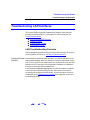
Example: Communicating Using VISA Assistant
VISA Assistant is an application program that uses the Agilent IO Libraries
to communicate with LAN, USB, and GPIB instruments. VISA Assistant
can automatically detect and assign VXIplug&play instrument drivers to
instruments.
VISA Assistant can also be used to send and receive strings to instruments
which support formatted I/O. For other instruments, VISA Assistant allows
you to read and write memory areas. VISA Assistant also describes
attributes that are associated with an instrument.
This example shows one way to use VISA Assistant to communicate with
an Agilent 33220A to return the ID string for the instrument. To open
VISA Assistant, click the Agilent IO Libraries Control icon (blue IO icon on the
Windows taskbar) and click Run VISA Assistant to display the VISA Assistant
main screen. Then, use the steps in this figure to return the identification
string for an Agilent 33220A.
2 Select the
Formatted I/O tab
1 Highlight
instrument
to be
addressed
4 Click the *IDN?
button
3 Select the SCPI
button
74
Connecting Instruments to GPIB
Step 6: Program Your Instruments
Step 6: Program Your Instruments
6 Program Your Instruments
This is an optional step. As desired, you can program instruments via the
GPIB interface using applications such as IVI-COM, VXIpnp, or VISA.
VISA: viopen (..."GPIB0::5::INSTR"...)
What’s in This Step? This is an optional step. After you have set up your GPIB system, as desired
you can program GPIB instruments from your PC via the GPIB interface.
See Programming Your Instruments for guidelines and examples.
75
Connecting Instruments to GPIB
Step 6: Program Your Instruments
76
Programming Your Instruments
! Programming Overview
! Addressing Instruments
! Example Programs
77
Programming Your Instruments
Programming Overview
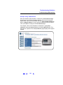
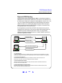
Programming Overview
This section provides an overview of programming instruments via LAN,
USB, or GPIB interfaces. Four example programs are included to
demonstrate generating a simple sine wave on an Agilent 33220A 20 MHz
Function/Arbitrary Waveform Generator using Standard Commands for
Programmable Instruments (SCPI).
The example programs are written in Microsoft Visual Basic 6.0 or Microsoft
Visual C++ for Agilent VISA-COM, IVI-COM, VISA, and VXIpnp I/O. They
are primarily intended to display SCPI commands for the 33220A and not to
demonstrate the programming environment or the I/O.
NOTE
The programs in this guide are protected by copyright.
Copyright © 2003 Agilent Technologies, Inc.
You have a royalty-free right to use, modify, reproduce and distribute the
programs listed in this guide (and/or any modified version) in any way
you find useful, provided that you agree that Agilent has no warranty,
obligations, or liability for any program content.
Agilent Technologies provides programming examples for illustration
only. All example programs assume you are familiar with the
programming language being demonstrated and the tools used to create
and debug procedures. Agilent support engineers can help explain the
functionality of Agilent software components and associated commands,
but they will not modify these samples to provide added functionality or
construct procedures to meet your specific needs.
78
Programming Your Instruments
Programming Overview
Obtaining
Instrument Drivers
Selected combinations of program environments and I/O are included in the
program examples in this guide. You will need to acquire the programming
environment and the I/O independent of the Agilent IntuiLink for the 33220A
Waveform Generator CD.
! Although not included in this guide, IDSK drivers are available and
are installed as part of the free IntuiLink for Arb software included on
this CD or may be obtained at http://www.agilent.com/find/intuilink.
! VISA-COM, IVI-COM, VISA, and VXIplug&play drivers for the Agilent
33220A may be obtained at http://www.agilent.com/find/33220A in the
Library under the heading Software, Firmware, & Drivers.
! USB ports ONLY work properly on Windows XP when the latest
Microsoft USB drivers from Windows XP Service Pack 1 have been
properly installed. In addition, if using USB on Windows 2000,
Agilent recommends you install the latest Service Pack for Windows
2000.
NOTE
Upgrading your XP PC to SP1 will probably not automatically update the
USB drivers. See www.agilent.com/find/connectivity to verify if correct
USB drivers are installed and to install correct drivers as required.
Installing Agilent IO If you want to modify the example programs or write your own programs and
compile them, a developer version of the Agilent E2094 I/O Libraries
Libraries
software must be installed. For GPIB, the Agilent E2094 I/O Libraries
software is provided with Agilent GPIB I/O products. The software should
have been loaded when you installed your GPIB interface card in your PC.
For USB or LAN, if you do not have a copy, you can order the Agilent E2094
I/O Libraries software on CD-ROM. You must have version M (order Agilent
product number E2094M) or a later version to support USB.
NOTE
You can obtain the Agilent I/O Libraries through the Agilent Developer
Network. Go to www.agilent.com/find/buyadn and purchase an ADN
Professional Membership. This gives you the right to download the latest
version of the Agilent I/O Libraries. Look for the Agilent I/O Libraries link
under “Downloads” on the ADN web site.
79
Programming Your Instruments
Programming Overview
Using I/O Objects in All Visual Basic programs in this guide use the Agilent VISA-COM object.
Other Visual Basic To use the I/O object in another Visual Basic project, use these steps:
Projects
1
Set the Reference. Set the reference to include the libraries in the
Project/References menu:
# "VISA COM 1.0 Type Library", corresponds to VISACOM.tlb
# "Agilent VISA COM Resource Manager 1.0", corresponds
to AgtRM.DLL
# "VISA COM 488.2 Formatted I/O 1.0", corresponds to the
BasicFormattedIO.dll
2
Create Formatted I/O Reference. Create the formatted I/O reference
with a statement such as "Dim Fgen As VisaComLib.FormattedIO488"
3
Create the New Object. Use "Set Fgen = New
VisaComLib.FormattedIO488" to create the actual object.
80
Programming Your Instruments
Addressing Instruments
Addressing Instruments
This section gives guidelines to address instruments via a LAN, USB, or
GPIB interface, including:
! Addressing Instruments via LAN
! Addressing Instruments via USB
! Addressing Instruments via GPIB
Addressing Instruments via LAN
To address instruments via the LAN, you must first configure the TCPIP LAN
Client interface using the IO Config utility. A summary of the applicable LAN
networking protocols follows. See LAN Interface Overview for a description
of LAN hardware, software, and network protocols.
LAN Networking
Protocols
There are two LAN networking protocols provided with the Agilent IO
Libraries software. You can use one or both of these protocols when
configuring your systems to use VISA and SICL over LAN.
! SICL-LAN Protocol is a networking protocol developed by Agilent
that is compatible with all VISA LAN products. This LAN networking
protocol is the default choice in the Agilent IO Libraries configuration
when configuring the LAN client. The SICL-LAN protocol on
Windows 98/Me/2000/NT/XP Professional supports VISA operations
over LAN to GPIB interfaces.
! VXI-11 (TCP/IP Instrument Protocol) is a networking protocol
developed by the VXIbus Consortium based on the SICL-LAN
Protocol that permits interoperability of LAN software from
different vendors who meet the VXIbus Consortium standards.
When using either of these networking protocols, the LAN software uses the
TCP/IP protocol suite to pass messages between the LAN client and the
LAN server. The server accepts device I/O requests over the network from
the client and then proceeds to execute those I/O requests on a local
interface (such as LAN).
81
Programming Your Instruments
Addressing Instruments
By default, the LAN Client supports both protocols by automatically detecting
the protocol the server is using. When a VISA viOpen or SICL iopen call is
performed, the LAN Client driver first tries to connect using the SICL-LAN
protocol. If that fails, the driver will try to connect using the VXI-11 protocol.
If you want to control the protocol used, you can configure more than one
LAN Client interface and set each interface to a different protocol. The
protocol used will then depend on the interface you are connecting through.
In VISA, the protocol used is determined by the configuration settings and
cannot be changed programatically. In SICL, the programmer can override
the configuration settings by specifying the protocol in the iopen string.
Example: Using Network Protocols
Some examples using VXI-11 and SICL-LAN protocol follow. Note that SICL
names are case-sensitive.
! iopen("lan[machineName]:gpib0,1") will use the configured
default protocol. If AUTO is configured, SICL-LAN protocol will be
attempted. If that is not supported, VXI-11 protocol will be used.
! iopen("lan;auto[machineName]:gpib0,1") will
automatically select the protocol (SICL-LAN if available and VXI-11
otherwise.)
! iopen("lan;sicl-lan[machineName]:gpib0,1") will use
SICL-LAN protocol.
! iopen("lan;vxi-11[machineName]:gpib0,1") will use
VXI-11 protocol.
! The TCPIP LAN Client also supports TCP/IP socket reads and
writes. To open a socket session, use
iopen("lan,socketNbr[machineName]"). For example,
iopen("lan,7777[machineName]") will open a socket
connection for socket number 7777 on 'machineName'.
82
Programming Your Instruments
Addressing Instruments
Configuring TCPIP
LAN Client
Interfaces
When you have configured VISA LAN Client interfaces, you can then use
the interface name specified during configuration in a VISA viOpen call of
your program. A summary of the steps to configure a TCPIP LAN Client
interface follows.
NOTE
A single TCPIP LAN Client interface can be used by any number of
VISA LAN Client interfaces. The main reason for having more than one
LAN Client configured is that you want to use different protocols
(such as SICL-LAN or VXI-11) in different VISA LAN Clients.
1
To configure TCPIP LAN Client interfaces using the IO Config utility,
click the Agilent IO Libraries Control icon (blue IO icon on the Windows
taskbar) and click Run IO Config. When the main screen appears,
highlight the TCPIP LAN Client (LAN Instruments) menu item and then
click the Configure button.
2
When the LAN Client screen appears, set the SICL Interface Name,
VISA Interface Name, Logical Unit number, Server Timeout value, and
Client Timeout Delta as required. Also, you can select the Default
Protocol (AUTO, VXI-11, or SICL-LAN) and choose whether or not to
Log Errors. Then, click the OK button.
83
Programming Your Instruments
Addressing Instruments
NOTE
After the system is configured, this screen may also display an Edit
VISA Config... button. Clicking this button allows you to manually
configure the interface as desired.
Example: Addressing LAN Instruments Using VISA/SICL
The TCPIP LAN Client interface system in this figure consists of a Windows
PC with a LAN (NIC) card and three LAN instruments. Instrument1 and
instrument2 are VXI-11.2 (GPIB Emulation) instruments and instrument3
is a VXI-11.3 LAN instrument.
For this system, the IO Config utility has been used to assign the LAN card
a VISA name of “TCPIP0” and SICL name of “lan”. For the addressing
examples, instrument1 has been addressed by its machine name,
instrument 2 has been addressed by its IP address, and instrument3 by
its LAN name (inst0).
Since unique names have been assigned by IO Config, you can now use the
VISA viOpen command or the SICL iopen command to open the I/O paths
to the GPIB instruments as shown in the figure.
84
Programming Your Instruments
Addressing Instruments
TCPIP LAN Client Addressing
Interface VISA/SICL Names
Windows PC
LAN
LAN Instruments
instrument1
machine name
5
VXI-11.2
GPIB Emulation
gpib0,5
1.2.3.4
IP address
3
VISA Name SICL Name
VXI-11.2
GPIB Emulation
gpib0,3
"TCPIP0"
"lan"
Network Interface Card
instrument3
VXI-11.3
LAN instrument
inst0
VISA/SICL Addressing (Using LAN Client)
VISA: viOpen (... "TCPIP0::instrument1::gpib0,5::INSTR"...)
viOpen (... "TCPIP0::1.2.3.4::gpib0,3::INSTR "...)
viOpen (... "TCPIP0::instrument3::inst0::INSTR"...)
Open IO path to LAN instrument at address 5
Open IO path to LAN instrument at address 3
Open IO path to LAN instrument3
SICL: iopen ("lan [instrument1]:gpib0,5")
iopen ("lan [1.2.3.4]:gpib0,3")
iopen ("lan [instrument3]:inst0")
Open IO path to LAN instrument at address 5
Open IO path to LAN instrument at address 3
Open IO path to LAN instrument3
85
Programming Your Instruments
Addressing Instruments
Addressing Instruments via USB
As desired, you can use an Alias name to address instruments via USB.
The USB Alias name associates an alias with a specific instrument.
You can use as a VISA rsrcName or SICL address instead of using the
instrument’s Vendor ID, Product ID, Serial Number, and Interface Number.
See the following steps to set, add, delete or change an Alias name.
1
Display the IO Config Main Screen. Click the blue IO icon (on the
Windows Taskbar) and select Run IO Config to display the IO Config
main screen.
If there is no entry in the Configured
Interfaces box for USB instruments,
you can highlight USB *USB
Instruments and click Configure to
configure the USB interface.
2
Display the USB Devices Dialog Box. Highlight the USB instrument
name in the Configured Interfaces box (VISA Name of USB0 and SICL
Name of usb0 for the previous figure). Then, click Edit... to display the
USB Devices dialog box.
This dialog box allows you to
associate a USB Alias name
with a specific instrument. The
association is based on the
instrument’s Vendor ID, Product
ID, Serial Number, and Interface
Number.
3
Add/Change/Delete Aliases. You can use the USB Devices dialog box
to change existing USB Alias names or to add or delete Alias names.
86
Programming Your Instruments
Addressing Instruments
Example: Assigning a USB Alias Name
This figure shows an example USB Devices dialog box for an Agilent
33220A. To change the USB Alias name, type the new name in the Alias
name box and then click the OK button. The Alias name can be used as
the preferred address for the VISA rsrcName and the SICL address.
For this example, the Alias name has been changed to .ArbGen. from the
default .UsbDevice1.. Thus, ArbGen can be used in viOpen() as the VISA
rsrcName parameter, rather than .USB0::2391::1031::MY43000029::0::INSTR..
Or, ArbGen can be used in iopen() as the SICL address parameter, rather
than the alternate address of .usb0[2391::1031::MY43000029::0]..
87
Programming Your Instruments
Addressing Instruments
Addressing Instruments via GPIB
To address instruments via a GPIB interface, you must first configure the
interface using the IO Config utility.
Steps to Configure a Steps to configure a GPIB interface for an Agilent 82350 PCI card follow.
Modify the steps as required if you use an 82341 ISA card.
GPIB Interface
1
To configure GPIB (82350 PCI) interfaces using IO Config, click the
Agilent IO Libraries Control icon (blue icon on the Windows taskbar)
and click Run IO Config. When the main screen appears, highlight the
GPIB *82350 PCI GPIB Card menu item (highlight GPIB 82341 GPIB
ISA Card for an 82341 card) and then click the Configure button.
88
Programming Your Instruments
Addressing Instruments
2
When the 82350 PCI GPIB Card Configuration screen appears, set the
VISA Interface Name, SICL Interface Name, Logical Unit and Bus
Address values as required. Then, click the OK button.
3
If you have more than one 82350 card in your system, repeat for
remaining cards.
NOTE
After the system is configured, this screen may also display an Edit VISA
Config... button. Clicking this button allows you to manually configure the
interface as desired.
89
Programming Your Instruments
Addressing Instruments
Example: Addressing GPIB Instruments Using VISA/SICL
This figure shows example VISA and SICL addressing for GPIB instruments
connected to a PC via a GPIB interface.
GPIB (82350) Addressing
Interface VISA/SICL Names
Windows PC
GPIB Cable
GPIB Instruments
5
VISA Name
SICL Name
"GPIB0"
"hpib7"
82350 GPIB Card #1
"GPIB1"
"hpib8"
82350 GPIB Card #2
3
3
VISA/SICL Addressing
VISA: viOpen (... "GPIB0::5::INSTR"...)
viOpen (... "GPIB0::3::INSTR"...)
viOpen (... "GPIB1::3::INSTR"...)
Open IO path to GPIB instrument at address 5 using 82350 Card #1
Open IO path to GPIB instrument at address 3 using 82350 Card #1
Open IO path to GPIB instrument at address 3 using 82350 Card #2
SICL: iopen ("hpib7, 5")
iopen ("hpib7,3")
iopen ("hpib8,3")
Open IO path to GPIB instrument at address 5 using 82350 Card #1
Open IO path to GPIB instrument at address 3 using 82350 Card #1
Open IO path to GPIB instrument at address 3 using 82350 Card #2
The GPIB interface system consists of a Windows PC with two 82350 GPIB
cards connected to three GPIB instruments via GPIB cables. For this
system, the IO Config utility has been used to assign GPIB card #1 a VISA
name of “GPIB0” and a SICL name of “gpib0”.
IO Config has also been used to assign GPIB card #2 a VISA name of
“GPIB1” and a SICL name of “gpib1”. With these names assigned to the
interfaces, the VISA/SICL addressing is as shown in the figure.
Since unique names have been assigned by IO Config, you can use the
VISA viOpen command to open the I/O paths to the GPIB instruments as
shown in this figure. Or, you can use the SICL iopen command to open the
I/O paths shown.
90
Programming Your Instruments
Example Programs
Example Programs
Four example programs follow to demonstrate sine waveform generation
for an Agilent 33220A 20 Mhz Function/Arbitrary Waveform Generator. The
example programs are essentially repeated to show the same functionality
with different programming environments and I/O. See the Agilent IntuiLink
for the 33220A Waveform Generator CD for other program examples. The
example programs are:
!
!
!
!
Example: Simple Sine Waveform (Visual Basic and VISA-COM)
Example: Simple Sine Waveform (Visual C++ and IVI-COM)
Example: Simple Sine Waveform (Visual C++ and VXIpnp)
Example: Simple Sine Waveform (Visual C++ and VISA)
Example: Simple Sine Waveform (Visual Basic and VISA-COM)
This program selects the function as “sine,” and then sets the frequency,
amplitude and offset of the waveform for an Agilent 33220A. The program
is written in Visual Basic 6.0 and uses VISA-COM.
Private Sub cmdSimpleSine_Click()
Dim io_mgr As VisaComLib.ResourceManager
Dim Fgen As VisaComLib.FormattedIO488
Set io_mgr = New AgilentRMLib.SRMCls
Set Fgen = New VisaComLib.FormattedIO488
Set Fgen.IO = io_mgr.Open(txtIO.Text)
On Error GoTo MyError
’ This program sets up a waveform by selecting the waveshape
’ and adjusting the frequency, amplitude, and offset.
With Fgen
.WriteString "*RST"
.IO.Clear
registers
’ Reset the function generator
’ Clear errors and status
.WriteString "FUNCtion SINusoid" ’ Select waveshape
91
Programming Your Instruments
Example Programs
’ Other options are SQUare, RAMP, PULSe, NOISe, DC, and USER
.WriteString "OUTPut:LOAD 50"
’ Set the load impedance in Ohms
’ (50 Ohms default)
’ May also be INFinity, as when using oscilloscope or DMM
.WriteString "FREQuency 2500"
.WriteString "VOLTage 1.2"
’
’
’
.WriteString "VOLTage:OFFSet 0.4" ’
Set the frequency.
Set the amplitude in Vpp.
Also see VOLTage:UNIT
Set the offset in Volts
’ Voltage may also be set as VOLTage:HIGH and VOLTage:LOW for
’ low level and high level
.WriteString "OUTPut ON"
’ Turn on the instrument output
End With
Exit Sub
MyError:
txtError = Err.Description & vbCrLf
Resume Next
End Sub
Example: Simple Sine Waveform (Visual C++ and IVI-COM)
This example program is intended for use with Microsoft Visual C++ 6.0
and the Agilent IVI-COM drivers. This program shows how to download an
arbitrary waveform using binary data. The program generates a damped
sine wave using 16,000 points.
NOTE
"VISA COM 1.0 Type Library" corresponds to VISACOM.tlb and "Agilent
33220 IVI COM Driver 1.0" corresponds to Agilent33220.DLL.
Use the statement "#import "Agilent33220.dll" no_namespace" to import
the Agilent 33220 IVI-COM Driver.
Create a variable of type IAgilent33220Ptr to hold the reference to the
object. To create the object, use
"Fgen.CreateInstance( __uuidof(Agilent33220) )".
92
Programming Your Instruments
Example Programs
#include <stdio.h>
#include <math.h>
// Specify the default address
#define DEFAULT_LOGICAL_ADDRESS OLESTR("GPIB0::10::INSTR")
#import
#import
#import
#import
"IviDriverTypeLib.dll" no_namespace
"IviFgenTypeLib.dll" no_namespace
"VisaCom.tlb" no_namespace
"Agilent33220.dll" no_namespace
void main()
{
BSTR
TxtAddress = DEFAULT_LOGICAL_ADDRESS;
long
Ncycles = 10;
/* Define number of sinewave cycles */
double Damp_factor = -5; /* Define damping factor */
double pi = 3.14159;
/* Define pi */
long
i;
IAgilent33220Ptr Fgen;
CoInitialize(NULL);
Fgen.CreateInstance(__uuidof(Agilent33220));
Fgen->Initialize(TxtAddress, VARIANT_FALSE, VARIANT_TRUE, "");
Fgen->Utility->Reset();// Reset the function generator
Fgen->Status->Clear();// Clear errors and status registers
Fgen->System->TimeoutMilliseconds = 40000; // Set timeout to 40
seconds for long download strings
Fgen->Output->Frequency = 5000;
// Output frequency is 5 kHz
Fgen->Output->Load = 50; // Output termination is 50 Ohms
Fgen->Output->Voltage->Amplitude = 5; // Output amplitude is 5 Vpp
// Compute waveform
fprintf(stderr, "Computing Waveform...\n");
// Create an array of data
SAFEARRAY *psa;
// Build a SafeArray of integer values.
SAFEARRAYBOUND bounds = {16000, 0};
93
Programming Your Instruments
Example Programs
psa = SafeArrayCreate (VT_I2, 1, &bounds);
// Populate the safearray
SHORT* Waveform;
SafeArrayAccessData(psa, (void**) &Waveform);
for (i = 1; i<= 16000; i++)
{
if(i < 14000)
{
Waveform[i-1] = (short)(sin(2.0 * pi * (double)Ncycles *
(double)i / 14000) * 2047
* exp(Damp_factor * (double)i / 14000) + 0.5);
}
else
{
Waveform[i-1] = 0;
}
}
SafeArrayUnaccessData(psa);
// Download data points to volatile memory
fprintf(stderr,"Downloading Arb...\n");
Fgen->ArbitraryWaveform->SetDataDAC(&psa);
Fgen->System->IO->WriteString("*OPC?", VARIANT_TRUE);
Fgen->System->IO->ReadString();
fprintf(stderr,"Download Complete\n");
// Download data points to volatile memory
Fgen->ArbitraryWaveform->CopyData("DAMP_SIN"); // Copy arb to
non-volatile memory
Fgen->ArbitraryWaveform->User = "DAMP_SIN";
// Select the active
arb waveform
Fgen->Output->Function = Agilent33220OutputFunctionUser; // Output
the selected arb waveform
Fgen->Output->State = VARIANT_TRUE;// Enable Output
Fgen->Close();
exit(0);
}
94
Programming Your Instruments
Example Programs
Example: Simple Sine Waveform (Visual C++ and VXIpnp)
This example program is intended for use with Microsoft Visual C++ 6.0
and requires VISA revision 2.0 and the Agilent Technologies 33220A VXIpnp
instrument driver installed. This program shows how to download an
arbitrary waveform using binary data. The program generates a damped
sine wave using 16,000 points.
#include
#include
#include
#include
#include
<string.h>
<stdlib.h>
<stdio.h>
<math.h>
"ag33250a.h"
#define CHECK(func)\
do {\
ViStatus _s = (func);\
if (_s < 0)\
{\
fprintf(stderr, "Error: %s returned %d\n", #func, _s);\
exit(0);\
}\
} while (0)
/* Specify the default address */
#define DEFAULT_LOGICAL_ADDRESS "GPIB0::10::INSTR"
void main()
{
ViSession
vi;
ViRsrc
TxtAddress = DEFAULT_LOGICAL_ADDRESS;
ViInt16 Waveform[16000];
long
Ncycles = 10;
/* Define number of sinewave cycles */
double Damp_factor = -5; /* Define damping factor */
double pi = 3.14159;
/* Define pi */
long
i;
ViInt16 reply;
CHECK(ag33250a_init(TxtAddress, 0, 0, &vi));
/* This funcion initializes the instrument */
CHECK(ag33250a_reset(vi));/* Reset the function generator */
CHECK(ag33250a_dcl(vi));/* Clear errors and status registers */
CHECK(ag33250a_formBord(vi, ag33250a_ARB_WAV_FORM_BOR_SWAP));
95
Programming Your Instruments
Example Programs
/* Swap data bytes (send LSB first) */
CHECK(ag33250a_freq(vi, 5000));
/* Output frequency is 5 kHz */
CHECK(ag33250a_outpLoad(vi, ag33250a_OUTPUT_LOAD_50));
/* Output termination is 50 Ohms */
CHECK(ag33250a_volt(vi, 5));
/* Output amplitude is 5 Vpp */
fprintf(stderr, "Computing Waveform...\n");
/* Calculate data points */
for (i = 1; i<= 16000; i++)
{
if(i < 14000)
{
Waveform[i-1] = (short)(sin(2.0 * pi * (double)Ncycles *
(double)i / 14000) * 2047
* exp(Damp_factor * (double)i / 14000) + 0.5);
}
else
{
Waveform[i-1] = 0;
}
/* Download data points to volatile memory from array */
fprintf(stderr, "Downloading Arb...\n");
CHECK(ag33250a_dataDacVolatile(vi, 16000, Waveform));
CHECK(ag33250a_opc_Q(vi, &reply));
fprintf(stderr, "Download Complete\n");
CHECK(ag33250a_dataCopy(vi, "DAMP_SIN"));
/* Copy arb to non-volatile memory */
CHECK(ag33250a_funcUserName(vi, "DAMP_SIN"));
/* Select the active arb waveform */
CHECK(ag33250a_funcShap(vi, ag33250a_OUTPUT_FUNC_USER));
/* Output the selected arb waveform */
CHECK(ag33250a_outpSetup(vi, ag33250a_OUTPUT_SETUP_ON));
/* Enable output */
CHECK(ag33250a_close(vi));
}
96
Programming Your Instruments
Example Programs
Example: Simple Sine Waveform (Visual C++ and VISA)
This example program is intended for use with Microsoft Visual C++ 6.0 and
requires VISA to be installed. This program uses the arbitrary waveform
function to download and output a square wave pulse with a calculated rise
time and fall time. The waveform consists of 4000 points downloaded to the
function generator as ASCII data.
#include
#include
#include
#include
<string.h>
<stdlib.h>
<stdio.h>
<visa.h>
#define CHECK(func)\
do {\
ViStatus _s = (func);\
if (_s < 0)\
{\
fprintf(stderr, "Error: %s returned %d\n", #func, _s);\
exit(0);\
}\
} while (0)
/* Specify the default address */
#define DEFAULT_LOGICAL_ADDRESS "GPIB0::10::INSTR"
void main()
{
ViSession
viDefaultRM, Instrument;
ViRsrc
TxtAddress = DEFAULT_LOGICAL_ADDRESS;
ViUInt32 actual;
char SCPIcmd[10000];
unsigned short i;
CHECK(viOpenDefaultRM(&viDefaultRM));
CHECK(viOpen(viDefaultRM, TxtAddress, VI_NULL, VI_NULL,
&Instrument));
/* Specify long seconds timeout for waveform download */
CHECK(viSetAttribute(Instrument, VI_ATTR_TMO_VALUE, 40000));
strcpy(SCPIcmd,"*RST\n"); /* Reset the function generator */
CHECK(viWrite(Instrument, SCPIcmd, (ViUInt32)strlen(SCPIcmd),
&actual));
97
Programming Your Instruments
Example Programs
strcpy(SCPIcmd,"*CLS\n"); /* Clear errors and status registers */
CHECK(viWrite(Instrument, SCPIcmd, (ViUInt32)strlen(SCPIcmd),
&actual));
/* Compute waveform */
fprintf(stderr, "Computing Waveform...\n");
strcpy(SCPIcmd, "DATA VOLATILE");
for(i = 1; i <= 5; i++)
/* Set rise time (5 points) */
sprintf(SCPIcmd, "%s,%3.1f", SCPIcmd, (double)(i - 1)/5);
for(i = 6; i <= 205; i++)
strcat(SCPIcmd, ",1");
/* Set pulse width (200 points) */
for(i = 206; i <= 210; i++)
/* Set fall time (5 points) */
sprintf(SCPIcmd, "%s,%3.1f", SCPIcmd, (double)(210 - i)/5);
for(i = 211; i <= 4000; i++)
strcat(SCPIcmd, ",0");
/* Set remaining points to zero */
strcat(SCPIcmd,"\n");
/* Download data points to volatile memory */
fprintf(stderr,"Downloading Arb...\n");
CHECK(viWrite(Instrument, SCPIcmd, (ViUInt32)strlen(SCPIcmd),
&actual));
fprintf(stderr,"Download Complete\n");
/* Set up arbitrary waveform and output */
strcpy(SCPIcmd,"DATA:COPY PULSE, VOLATILE\n"); /* Copy arb to
non-volatile memory */
CHECK(viWrite(Instrument, SCPIcmd, (ViUInt32)strlen(SCPIcmd),
&actual));
strcpy(SCPIcmd, "FUNCtion:USER PULSE\n"); /* Select the active
arb waveform */
CHECK(viWrite(Instrument, SCPIcmd, (ViUInt32)strlen(SCPIcmd),
&actual));
98
Programming Your Instruments
Example Programs
strcpy(SCPIcmd, "FUNCtion:SHAPe USER\n"); /* Output the selected
arb waveform */
CHECK(viWrite(Instrument, SCPIcmd, (ViUInt32)strlen(SCPIcmd),
&actual));
strcpy(SCPIcmd, "OUTPut:LOAD 50\n"); /* Output termination is 50 Ohms
*/
CHECK(viWrite(Instrument, SCPIcmd, (ViUInt32)strlen(SCPIcmd),
&actual));
strcpy(SCPIcmd, "FREQuency 5000;VOLTage 5\n"); /* Output frequency
is 5 kHz @ 5 Vpp */
CHECK(viWrite(Instrument, SCPIcmd, (ViUInt32)strlen(SCPIcmd),
&actual));
strcpy(SCPIcmd, "OUTPut ON\n"); /* Enable output */
CHECK(viWrite(Instrument, SCPIcmd, (ViUInt32)strlen(SCPIcmd),
&actual));
CHECK(viClose(Instrument));
CHECK(viClose(viDefaultRM));
}
99
Programming Your Instruments
Example Programs
100
Installing I/O Software
! Pre-Installation Checks
! Installing Your Software
101
Installing I/O Software
Pre-Installation Checks
Pre-Installation Checks
Before you install I/O software on your PC, verify that your system meets the
minimum hardware and software requirements to install and use the Agilent
IO Libraries for the USB, LAN, or GPIB interface. Adding additional RAM
may improve system performance. For example, this table shows minimum
hardware and software requirements to install the software contained on the
Agilent IntuiLink for the 33220A Waveform Generator CD.
Hardware
Minimum Requirements
PC Operation/Memory
Pentium 200 MHz operation and 64 MBytes RAM
Free Disk Space
80 MBytes
Ethernet Connections (LAN)
10BASE-T or 100BASE-TX compliant
PCI Bus Slot (GPIB)
At least one PCI Bus Slot (to install Agilent 82350B)
ISA Bus Slot (GPIB)
At least one ISA Bus Slot (to install Agilent 82341A)
USB Port (USB)
At least one USB Port
Software
Minimum Requirements
Operating System
Windows 98/Me/NT 4.0 (SP5 or greater)/2000/XP (LAN/GPIB)
Windows 98 (SE)/Me/2000/XP (USB)
Web Browser (Optional)
Internet Explorer 5.0 or higher. (Internet Explorer 5.5 or higher is
recommended.)
Agilent IO Libraries
Installation Sizes
- Core Installation (LAN only)
- Run-Time Installation (adds hardware drivers)
- Full Installation (without manuals)
- Full Installation (with manuals)
- Add Adobe Acrobat Reader (version 5.05)
102
5 Mb
9 Mb
14 Mb
34 Mb
11 Mb (addl)
Installing I/O Software
Installing Your Software
Installing Your Software
Suggested steps follow to select and install I/O software for your application.
1
Determine Your Application Tasks. One way to select the I/O software
for your application is to use the product life cycle approach. As
shown in this figure, as the product life cycle moves from R&D to
Manufacturing, tasks for the product typically change from Product
Design to Product Characterization to Product Test. The associated
programming levels range from no programming to minimal
programming to extensive programming.
Agilent IntuiLink is typically used for Product Design or Product
Characterization, while IVI-COM and VXIpnp drivers are typically
used for Product Characterization or Product Test. For any software
application that uses VISA (such as Agilent IntuiLink), a version of
the Agilent IO Libraries (developer or runtime) is required.
Life Cycle
Typical Tasks/
Programming
Level
R&D
Manufacturing
Product Design
Product Characterization
Product Test
Product design
(simulation and modeling)
and verification of design
Design validation (stimulus)
and product characterization
(stimulus/response)
Create optimized
sequences of tests
with specifications
No Programming
Application
Software
Minimal Programming
Agilent IntuiLink
I/O Libraries
Software
I/O Interface
Extensive Programming
IVI-COM and VXIpnp Drivers
Agilent IO Libraries
USB
LAN
Instruments
Instruments
103
GPIB
Installing I/O Software
Installing Your Software
2
Select Application and Agilent IO Libraries Software. The next step is to
select the I/O software application(s) and Agilent IO Libraries version
you want to install on your PC. This table gives guidelines for using IO
software and Agilent IO Libraries version (developer or runtime). See
substep 3, following, to select the Agilent IO Libraries version.
Use This Software:
When You Want to:
Instrument Web Browser (Product Design or Product Characterization)
Provides a “soft front panel” displayed on your Web
Browser that you can use to control the instrument.
Remotely communicate with instruments from your
PC, but do not need to program the instruments.
(The IO Libraries are not required.)
Agilent IntuiLink (Product Design or Product Characterization)
Provides a “soft front panel” specific to an instrument
that you can use to control instruments.
Remotely communicate with instruments from your
PC, but do not need to program the instruments
(The IO Libraries are required.)
IVI-COM Drivers (Product Characterization or Product Test)
Interchangeable Virtual Instruments (IVI)-COM
Drivers provide hardware-independent programming
syntax for instruments that perform the same function
(DMMs, Counters, Switches, etc.).
Develop new applications using Visual Basic,
Visual C++, etc. and the IVI-COM drivers. In most
cases, new code must be developed for programs
using IVI-COM drivers.
VXIplug&play Drivers (Product Characterization or Product Test)
VXIplug&play functions provide a set of instrumentspecific functions you can use for programming
instruments using Visual Basic, Visual C++, etc.
Develop or modify existing applications using
Visual Basic, Visual C++, etc. You can use existing
code if the same driver (or update) is supported on
both the old and new instrument.
Agilent IO Libraries (Developer) (All Tasks)
The developer version of the Agilent IO Libraries
allows you to program your instruments using Visual
Basic, Visual C++, etc. and to communicate with
instruments via USB, LAN, or GPIB.
Use the developer version when you want to
develop or modify existing applications using Visual
Basic, Visual C++, etc. and VISA. Applications
written with VISA for other instruments can be
ported to your instruments with little or no
modification.
Agilent IO Libraries (Runtime) (All Tasks)
The runtime version of the Agilent IO Libraries is a
subset of the Developer version. With the runtime
version of the libraries, you can communicate with
instruments, but you cannot program the instruments
using VISA.
104
Use the runtime version when you want to run
existing applications that use VISA to communicate
with instruments, but you do not need to modify or
develop the instrument communication code in the
application program.
Installing I/O Software
Installing Your Software
3
Select the Agilent IO Libraries Version. As noted, there are two versions
of the Agilent IO Libraries: developer and runtime. Use the developer
version if you want to communicate with instruments and to program
instruments using VISA. Use the runtime version if you want to
communicate with instruments, but do not need to program the
instruments.
This table shows the version of the Agilent IO Libraries required for LAN,
USB, and GPIB interfaces and typical programming methods.
Interface
When to Use this Interface:
LAN
A LAN is the recommended method
to connect instruments together in
applications such as new test
systems.
Programming
Method
GPIB
USB is a quick and easy way to
connect instruments to PCs on a
benchtop. Typically, you can use
USB to connect instruments to a PC
for benchtop R&D testing.
GPIB should be used only in a
system that is already using GPIB
to connect instruments. GPIB is not
recommended for new systems.
Need RunTime IO
Libraries
IVI-COM
!
VXIplug&play
!
!
IVI-COM
!
VXIplug&play
!
VISA*
!
IVI-COM
!
VXIplug&play
!
VISA
No IO
Libraries
Needed
!
Sockets
VISA
USB
Need
Developer
IO Libraries
!
* Revision M.01.00 or later of the Agilent IO Libraries is required for USB
4
Install Your Software. This table shows the media you can use to install
your selected I/O software on your PC for both runtime and developer
environments. Follow the instructions on the media to install the
software.
NOTE
Installing Agilent IntuiLink or the IVI-COM drivers also automatically
installs a runtime version of the Agilent IO Libraries. Revision M.01.00 or
later of the Agilent IO Libraries is required for programming via USB.
105
Installing I/O Software
Installing Your Software
For This
Environment:
Use This
Media:
That May Include:
To Get This Media:
Runtime
(cannot program
instruments)
Instrument
CD
- Agilent IntuiLink
- IVI-COM Drivers
- VXIpnp Drivers
- Agilent IO Libraries (runtime)
- Agilent VEE evaluation copy
Ships with the Instrument. Check
the instrument CD to see which
items are included on the CD.
Web
- Agilent IO Libraries (runtime)
Download the libraries from
www.agilent.com/connectivity
E2094M
- Agilent IO Libraries (developer) Order the E2094M product from
Agilent. See Contacting Agilent
for addresses.
Developer
(can program
instruments)
Example: Installing Software from the 33220A CD
For example, the Agilent IntuiLink for the 33220A Waveform Generator CD
that ships with the 33220A instrument includes these items that you can
install on your PC, as desired:
- IntuiLink Waveform Editor
- ActiveX Software Components
- VXI plug&play Driver
- IVI-COM Driver
- Agilent IO Libraries (runtime)
- Programming Examples
- Manuals
- Agilent VEE (evaluation copy)
For this CD, installing Agilent IntuiLink or the IVI-COM Drivers also
automatically installs a runtime version of the Agilent IO Libraries. (If you
want to install a developer version of the Agilent IO Libraries, you must
install the libraries from the CD included in the E2094M product.
106
Troubleshooting Guidelines
! Troubleshooting LAN Interfaces
! Troubleshooting USB Interfaces
! Troubleshooting GPIB Interfaces
107
Troubleshooting Guidelines
Troubleshooting LAN Interfaces
Troubleshooting LAN Interfaces
This section shows suggested troubleshooting steps for LAN interfaces,
including the following items. For information on TCP/IP networks, see
TCP/IP Network Basics.
!
!
!
!
LAN Troubleshooting Overview
Hardware Checks
Communication Checks
Web Browser Checks
LAN Troubleshooting Overview
LAN troubleshooting guidelines follow. However, the first step is to check for
normal operation, as shown in Checking for Normal Operation.
Checking for Normal Before beginning LAN troubleshooting steps, you should first check to see
what symptoms appear when you attempt to connect to instruments via the
Operation
LAN. To see if your PC has network access to an instrument, open the Web
Browser on the PC and type in the instrument’s IP address (or Hostname,
if known) on the web browser’s address line.
If the instrument’s Welcome Page appears, this PC has network connection
to the instrument. Repeat this step for each instrument on the network.
An example for the Agilent 33220A follows. If normal operation cannot be
established, go to Troubleshooting Flowchart for a suggested sequence of
troubleshooting steps.
108
Troubleshooting Guidelines
Troubleshooting LAN Interfaces
Example: Using a Web Browser
Since the 33220A is Web-enabled, to display the 33220A Welcome Page,
first determine the 33220A IP address from the instrument’s front panel
display. Next, open your web browser and type ‘http://<33220A IP Address>’,
where <33220A IP Address> is the IP address displayed on the front panel.
Then, press Enter to display the 33220A Welcome page.
For example, if the current IP address is 169.254.3.2, typing http://
169.254.3.2 and pressing Enter displays the 33220A Welcome page. This
figure shows a portion of an example Welcome page display for the Agilent
33220A.
109
Troubleshooting Guidelines
Troubleshooting LAN Interfaces
Troubleshooting
Flowchart
If normal operation cannot be established, see this flowchart for suggested
troubleshooting steps. We suggest you start at Hardware Checks.
1 Hardware Checks
2 Communication Checks
3
Web Browser Checks
Typical Causes
Typical Causes
Typical Causes
Bad cables/connections or
power not ON for PC or
instruments.
Improper or Incorrect IP
addresses and/or Hostnames
Web Browser settings are
incorrect.
Check Operating Lights
on PC/Devices
Use the ping Command
Check Proxy Settings
Check Cables/
Connections/Power
Use route add (Private
LAN Only)
Set Cache and Page
Refresh
Enable Javascript
After Doing These Checks:
After Doing These Checks:
After Doing These Checks:
- If the cause is not identified,
see Communication Checks
- If the cause is not identified,
see Web Browser Checks
- If the cause is identified as an
instrument hardware problem,
contact Agilent.
- If the cause is identified as an
instrument problem, but the
problem cannot be fixed,
contact Agilent.
- If the cause is not identified
or the problem cannot be
fixed, contact Agilent for
support.
110
Troubleshooting Guidelines
Troubleshooting LAN Interfaces
Hardware Checks
The first step in troubleshooting LAN networks is to check the hardware
setup for all devices connected to the LAN. This table shows some possible
causes and corrective actions.
After you have made the hardware checks and taken corrective actions as
required, again check for normal operation as shown in Checking for Normal
Operation. If normal operation has not been established, go to
Communication Checks..
Possible Cause(s)
Corrective Action(s)
PC Suspended or Network
Interface Card (NIC) not
operational.
Verify that the PC is not in a Suspended
power state. If the lights on the NIC are
ON, the NIC is probably operational.
Ethernet Hub or Switch not
ON or not operational.
Verify that the hub/switch is powered ON.
If the hub/switch lights are ON, the hub/
switch is probably operational.
Instruments are not ON or
are not operational.
Verify that all instruments are powered ON.
If the power-on light is ON, the instrument
is probably operational. Also, check the
NIC lights on the instruments. If the NIC
lights are ON, the hardware LAN
connection to the instrument is OK.
Cables are not properly
connected
Check LAN cable connections between
PC, hub/switch, and instruments. Tighten
connectors or replace cables as required.
111
Troubleshooting Guidelines
Troubleshooting LAN Interfaces
Communication Checks
If there are no hardware problems, but normal communication has not been
established, the next step is to make communication checks using the
ping command. In addition, for private LANs only, you may need to use the
route add command to establish communication. If you can establish
communication using these checks, but the web browser display is not
correct, go to Web Browser Checks.
Using the ping
Command
An example to verify communication using the ping command follows.
NOTE
If you cannot verify communication to connected instruments using the
ping command, try using ping to a device at a known address. If this is
successful, the problem is likely with the instrument (for site LANs) or
with the hub/switch or instruments (for private LANs).
Example: Verifying Communication Using the ping Command
For example, on Windows 2000 to send a ping command from your PC to
an instrument click Start | Programs | Accessories | Command Prompt.
When the Command Prompt window opens, type ping <IP_address>,
where <IP_address> is the IP address of the instrument, and then press
the Enter key. A typical display follows where ping was successful.
112
Troubleshooting Guidelines
Troubleshooting LAN Interfaces
A typical display follows where ping was not successful.
Using the route add “If you are having difficulty with a private LAN (using a hub, switch, or even a
simple crossover cable), a possible cause for no communication between
Command
the PC and connected instruments is that the PC has not recognized that
it is connected to two different subnets. (See Local and Remote Networks for
details.)
One way to put the PC and the instrument on the same subnet is to use
route add <Instrument IP Address> <PC IP Address> from the Command
Prompt. If this action does not correct the problem, go to Web Browser
Checks.)
NOTE
If your devices are connected to site LAN, do not use the route add
command.
Example: Using the route add Command
For example, on Windows 2000 to send a use the route add command,
click Start | Programs | Accessories | Command Prompt. When the
Command Prompt window opens, type route add <Instrument IP Address>
<PC IP Address>, where <Instrument IP_address> is the IP address of the
instrument and <PC IP Address> is the IP address of the instrument, and
then press the Enter key.
113
Troubleshooting Guidelines
Troubleshooting LAN Interfaces
For example, if the IP address of your PC is 155.139.103.152 and the
instrument address is 169.254.58.10, the two devices are probably on
different subnets. To add the instrument to the subnet for the PC, use
one of the following:
! route is lost when the PC is rebooted
route add 169.254.58.10 155.139.103.152
or
! route persists when the PC is rebooted
route -p add 169.254.58.10 155.139.103.152
Web Browser Checks
If all hardware connections are OK and you have been able to establish
communication between your PC and instruments, but the web browser
display is incorrect or the web browser display does not appear at all, the
problem could be that the web browser settings are incorrect.
Suggesed steps follow to check your web browser settings, including the
following items. If doing these steps does not correct the problem, contact
Agilent for support. See Contacting Agilent for addresses.
! Checking Proxy Settings
! Setting Cache and Page Refresh
! Enabling Javascript
Checking Proxy
Settings
A proxy is a service running on a computer that takes an information request
from another computer and passes the request on as if the request was its
own. Typically, many companies use proxies to control access from their
internal network to the external Internet.
In some situations, you may not be able to communicate with the instrument
if you are using a proxy server. Typically, the web page will time out because
the requested address is not accessible by the network, although the correct
IP address or hostname is entered into the web browser address field.
To fix this communication problem between the web browser and the
instrument web server, the browser must be informed that any requests to
the instrument should not utilize a proxy.
114
Troubleshooting Guidelines
Troubleshooting LAN Interfaces
Example: Setting Proxy Notification (Internet Explorer 5.0 and above)
Example steps check proxy settings for Internet Explorer versions 5.0 and
above follow. The steps are for Windows 2000. Modify the steps as required
for other operating systems.
1
Click Start | Settings | Control Panel to display the Control Panel
2
From Control Panel, double-click Internet Options to display the
Internet Properties dialog box
3
From the Internet Properties dialog box, select the Connections tab
4
Click the LAN Settings… button under Local Area Network (LAN)
settings
Setting Cache and
Page Refresh
5
Under Proxy server, if “Use a proxy server” is checked, click the
Advanced… button
6
Under Exceptions, add the IP address of the instrument or a fullyqualified domain name (such as myinstr.example.com) to the list
box called “Do not use proxy server for addresses beginning with:”
Use a semicolon (;') to separate multiple entries.
7
Click the OK button on the bottom of the Internet Options dialog box
to make changes active.
For faster performance, most web browsers cache web pages. If a page is
cached, an image of the web page is stored locally. When you navigate to
a page that has already been viewed, the browser will load the page from its
cache rather than loading it from the network.
Usually, this process works well for static web pages. However, this process
may cause problems for 'dynamically' changing web pages. This problem
may occur when you are navigating using the browser’s forward/back/
refresh options.
Doing this usually causes the browser to first look in its cache to see if the
page exists. If the page is cached, the browser displays the page from the
cache instead of going to the network to update changes. Since instrument
web pages are dynamic in nature, the cache may contain content that is
outdated. If you see a problem where dynamic pages are not being updated
automatically, the browser should be instructed to check for newer versions
of a web page on every page visit.
115
Troubleshooting Guidelines
Troubleshooting LAN Interfaces
Example: Cache and Page Refresh (Internet Explorer 5.0 and above)
Example steps for cache and page refresh for Internet Explorer versions 5.0
and above follow. The steps are for Windows 2000. Modify the steps as
required for other operating systems.
1
Click Start | Settings | Control Panel to display the Control Panel
2
From Control Panel, double-click Internet Options to display the
Internet Properties dialog box.
3
From the Internet Properties dialog box, select the General tab
4
Under Temporary Internet files, click the Settings... button to display
the Settings dialog box
5
Under Check for newer versions of stored pages:, click the “Every visit
to the page” radio button (“Automatically” should be OK for Internet
Explorer 5.5 and >)
6
Click the OK button on the Settings page to accept the change
7
Click the OK button on the bottom of the Internet Options dialog box to
make changes active
NOTE
If the previous steps to not resolve the problem, you may want to clear
the cache. To do this, repeat steps 1 - 4. Then, in the Temporary Internet
files, click the Delete Files... button to display the Delete Files dialog box.
Click OK to delete the files and clear the cache.
116
Troubleshooting Guidelines
Troubleshooting LAN Interfaces
Enabling Javascript Instruments that are Web-enabled may generate web pages that depend
on Javascript and Frames. For proper operation, you may need to enble
Javascript.
Example: Enabling Javascript (Internet Explorer 5.0 and above)
Example steps for enabling Javascript for Internet Explorer versions 5.0 and
above follow. The steps are for Windows 2000. Modify the steps as required
for other operating systems.
1
Click Start | Settings | Control Panel to display the Control Panel
2
From Control Panel, double-click Internet Options to display the
Internet Properties dialog box.
3
From the Internet Properties dialog box, select the Securities tab
4
Click the Custom Level… button
5
Under Settings, scroll down to the category called Scripting
6
Click the Enable radio button under Active Scripting
7
Click the Enable radio button under Scripting of Java applets
8
Click the OK button on bottom of page to accept security settings
9
When the Warning! dialog box appears, click the YES button when
prompted for “Are you sure you want to change the security settings for
this zone?”
10
Click the OK button on the bottom of the Internet Options dialog box to
make changes active.
117
Troubleshooting Guidelines
Troubleshooting USB Interfaces
Troubleshooting USB Interfaces
This section shows suggested troubleshooting steps for Universal Serial Bus
(USB) interfaces, including:
! USB Troubleshooting Overview
! USB Hardware Checks
! USB Software Checks
NOTE
The troubleshooting procedures in this section are primarily oriented
toward USB instruments and the Agilent IO Libraries. Consult your
instrument’s User’s Guide for troubleshooting details for the instrument.
USB Troubleshooting Overview
This figure shows a typical USB interface with a PC and a USB instrument.
A suggested troubleshooting flowchart for USB instruments and the Agilent
IO Libraries follows. We suggest you start at USB Hardware Checks and
then go to USB Software Checks, as required.
118
Troubleshooting Guidelines
Troubleshooting USB Interfaces
USB Hardware Checks
USB Software Checks
Typical Causes
Typical Causes
No power on USB bus or hub
or device turned off by Windows
Plug and Play Manager.
Agilent IO Libraries not installed
or USB drivers not installed or
improper IO Libraries operation.
Check Cable
Connections/Damage
Verify Agilent IO Libraries
Installation
Check PC/Instrument
Functions
Verify USB Driver
Installation
Check Device Manager
Check IO Control
Operation
After Doing These Checks:
After Doing These Checks:
- If the cause is not identified,
see Software Checks.
- If the cause is not identified
or the problem cannot be
fixed, contact Agilent for
support.
- If the cause is identified as a
hardware problem, contact
Agilent to return the device.
119
Troubleshooting Guidelines
Troubleshooting USB Interfaces
USB Hardware Checks
This section gives guidelines to make hardware troubleshooting checks for
connected USB instruments. We suggest you start your troubleshooting
sequence by performing the following hardware checks. If performing the
hardware checks do not correct the problem, go to USB Software Checks.
Check Cable
Connections/
Damage
Check all USB cables for good connection to the USB connector on your
PC, to all USB hubs (if installed) and the USB cable connections to
connected USB instruments. An improperly attached USB connector
can cause the interface to malfunction.
Check all USB cables for cuts/damage and check for bent/misaligned/
crushed connector pins. Replace cables as required. If these actions do
not solve the problem, try disconnecting and reconnecting (or replacing)
USB cables. If the cable checks do not solve the problem, go to
Check PC/Instrument Functions
Check PC/
Instrument
Functions
Verify that all USB hubs, and all connected USB instruments are functional
and are powered ON. Verify that host computer is not in a Suspended power
management state. If these actions do not solve the problem, reboot the PC.
If this does not solve the problem, go to Check Device Manager.
Check Device
Manager
You can use the Windows Device Manager to reinstall the USB instrument
driver, as required. For example, with Windows 2000, go to Control Panel by
selecting Start | Settings | Control Panel. Then, select System | Hardware |
Device Manager. From Device Manager, select the USB Test and Measurement
Device and then click Properties.
Tab to Driver and click Reinstall Driver. This will allow the Windows Plug
and Play Manager to begin searching for a driver for the instrument. Since
Device Manager may have disabled the instrument, click Enable to restart
the instrument.
NOTE
Windows may place a misbehaving USB device in an "Unknown device"
category. To see if this has happened, change the View in Device Manager
by selecting View | Show Hidden Devices. Next, right-click the Universal
Serial Bus Controllers Unknown device and select Uninstall. Then, select
Device Manager | Action | Scan for hardware changes.
120
Troubleshooting Guidelines
Troubleshooting USB Interfaces
USB Software Checks
This section provides guidelines to make software troubleshooting checks
for connected USB instruments. If you have not already done so, we suggest
you start your troubleshooting sequence by performing the hardware checks
in USB Hardware Checks. If performing the hardware and then the software
checks does not correct the problem, contact Agilent for instructions. See
Contacting Agilent for addresses.
Verify Agilent IO
1
Libraries Installation
Check Agilent IO Libraries Version. If a version of the Agilent IO
Libraries has been installed, a blue IO icon is normally displayed on
the Windows taskbar (on the lower right-hand side of the screen).
Blue IO Icon
# If the IO icon is displayed, click the icon and click About
Agilent IO Libraries Control to display the version. The version
must be M.01.00 or greater.
# If the IO icon is not displayed, a version may still be installed.
To check this, click Start | Programs and look for the Agilent IO
Libraries program group.
# If this group is displayed, click Agilent IO Libraries | IO Control
to display the IO icon. Then, click the icon and click About
Agilent IO Libraries Control to display the installed version
(must be M.01.00 or greater).
# If neither the IO icon nor the Agilent IO Libraries program
group is displayed, no Agilent IO Libraries are installed.
In this case, or if the installed version is not M.01.00 or
greater, you must install the newer version (see substep 2
following).
121
Troubleshooting Guidelines
Troubleshooting USB Interfaces
2
Install Agilent IO Libraries (as Required). If Version M.01.00 or greater
of the Agilent IO Libraries is not installed on your PC, use this substep.
Otherwise, skip to Verify USB Driver Installation.
a
Remove the USB cable from the USB port on the instrument.
b Uninstall the IO Libraries from the Agilent IO Libraries Control
(blue IO icon)
c
Re-attach the USB cable to the USB port on the instrument.
d If this does not correct the problem, go to Verify USB Driver
Installation.
Verify USB Driver
Installation
1
Check for USB Driver Files. Files are listed in their default directories
for Windows 2000 and Windows 98 (SE)/Me/XP. Verify that the driver
files are installed. If they are installed, go to Check IO Control
Operation. If not, go to substep 2 following.
NOTE
USB ports ONLY operate properly on Windows XP when the latest
Microsoft USB drivers from Windows XP Service Pack 1 have been
properly installed. However, upgrading your XP PC to SP1 will probably
not automatically update the USB drivers. See www.agilent.com/find/
connectivity to verify if correct USB drivers are installed and to install
correct drivers as required.
Windows 2000
Program Files
C:/Program Files/Agilent/IO Libraries/drivers/agusb48832.dll
Driver Files
C:/Winnt/system32/drivers/ausbtmc.sys
.inf Files
C:/Winnt/inf/ausbtmc.inf
Windows 98 (SE)/Me/XP
Program Files
C:/Program Files/Agilent/IO Libraries/drivers/agusb48831.dll
Driver Files
C:/Windows/system32/drivers/ausbtmc.sys
.inf Files
C:/Windows/inf/ausbtmc.inf
122
Troubleshooting Guidelines
Troubleshooting USB Interfaces
2
Check IO Control
Operation
Uninstall/Reinstall the Agilent IO Libraries. If the driver files are not
found, uninstall the Agilent IO Libraries by inserting the Instrument
CD and following the instructions to remove the libraries. Then, install
Version M.01.00 or greater of the Agilent IO Libraries.
When the Agilent IO Libraries were installed, an IO Control was created.
When the IO Control is active, it is displayed as a blue IO icon on the
Windows taskbar. If the IO Control is deactivated, SICL/VISA applications
that are running with the instrument will be unable to open sessions.
By default, the IO Control is always active after the Agilent IO Libraries are
installed and the blue IO icon is displayed. However, the IO Control may be
active even though the blue IO icon is not displayed. There are two ways that
the blue IO icon can be hidden:
# Clicking Hide Agilent IO Libraries Control. Clicking the blue
IO icon and then clicking Hide Agilent IO Libraries Control
hides the blue IO icon, but does not deactivate the IO Control.
# Clicking Exit. Clicking the blue IO icon and then clicking Exit
causes a dialog box to appear that asks you if you want to
terminate the Agilent IO Libraries Control. Clicking Yes hides
the blue IO icon and deactivates the IO Control.
If the blue IO icon is not displayed, either the blue IO icon display has been
turned off and/or the IO Control is not active. In this case, click Start |
Programs | Agilent IO Libraries and then click IO Control to re-start the
IO Control and to display the blue IO icon.
123
Troubleshooting Guidelines
Troubleshooting GPIB Interfaces
Troubleshooting GPIB Interfaces
This section shows suggested troubleshooting steps for an Agilent 82350
GPIB interface, including:
!
!
!
!
GPIB Troubleshooting Overview
GPIB Hardware Checks
GPIB Software Checks
Agilent IO Libraries Checks
NOTE
The troubleshooting procedures in this section are primarily oriented
toward an Agilent 82350 GPIB card and the Agilent IO Libraries.
Consult your instrument’s User’s Guide for troubleshooting details for
the instrument.
GPIB Troubleshooting Overview
This figure shows a typical GPIB system with a PC and two GPIB
instruments. A suggested troubleshooting flowchart for GPIB cards, installed
instruments, and the Agilent IO Libraries follows. We suggest you start at
Step 1 and then go to Step 2 and then to Step 3, as required.
GPIB Cable
PC
Instrument
124
Instrument
Troubleshooting Guidelines
Troubleshooting GPIB Interfaces
1
GPIB Hardware Checks
2
GPIB Software Checks
3
IO Libraries Checks
Typical Causes
Typical Causes
Typical Causes
Bad GPIB cables/connections
or power not ON for PC or
instruments.
GPIB card drivers not installed
or GPIB card not properly
configured.
Agilent IO Libraries not
installed or improper IO
Libraries configuration
Check Cables/
Connections/Power
Check for GPIB
Driver Files
Check IO Libraries
Installation
Check Device Manager
Disable IO Config
Auto-Detection
Check IO Control
Operation
Other Hardware Checks
Check BIOS/Interrupts
Settings
Install Libraries (if GPIB
Already Installed)
Set 82350 Read/Write
Performance Mode
After Doing These Checks:
After Doing These Checks:
After Doing These Checks:
- If the cause is not identified,
see GPIB Software Checks
- If the cause is not identified,
see Agilent IO Libraries Checks
- If the cause is identified as an
82350 hardware problem,
contact Agilent to return the
82350.
- If the cause is identified, but the
problem cannot be fixed, contact
Agilent for support.
- If the cause is not identified
or the problem cannot be
fixed, contact Agilent for
support.
125
Troubleshooting Guidelines
Troubleshooting GPIB Interfaces
GPIB Hardware Checks
This section gives guidelines to make hardware troubleshooting checks for
the GPIB card (such as an Agilent 82350), including:
!
!
!
!
!
Check Cables/Connections/Power
Check Device Manager
If Sound Card Does Not Work
If Data Transfers to Devices Fail
If IO Config Finds 82350 Card with Serial Number ffffffff
Check Cables/
We suggest you start your troubleshooting sequence by performing the
Connections/Power following hardware checks. If the hardware checks do not solve the problem,
see GPIB Software Checks.
NOTE
There are no user-servicable parts for the 82350. If you suspect a
hardware failure for the 82350, contact Agilent for instructions to return
the unit. See Contacting Agilent for telephone numbers/web site address.
1
Check GPIB Cable Connections. Check all GPIB cables for good
connection to the GPIB connector on the 82350 installed in your PC
and the GPIB cable connections between all connected GPIB
instruments. An improperly attached GPIB connector can cause the
bus to malfunction.
2
Check GPIB Cables for Damage. Check all GPIB cables for cuts/
damage and check for bent/misaligned/crushed connector pins.
Replace cables as required.
3
Disconnect/Reconnect GPIB Cables. If Steps 1 and 2 do not solve the
problem, try disconnecting and reconnecting (or replacing) GPIB
cables.
4
Check PC/Instrument Power-on. Verify that the PC and all connected
GPIB instruments are functional and are powered ON. Verify that host
computer is not in a Suspended power management state.
5
Reboot Your PC. If doing Steps 1, 2, 3 or 4 does not solve the problem,
reboot the PC. If this does not solve the problem, go to
Check Device Manager.
126
Troubleshooting Guidelines
Troubleshooting GPIB Interfaces
Check Device
Manager
You can use the Windows Device Manager to reinstall the 82350 or
equivalent, as required. For example, with Windows 2000, go to Control
Panel by selecting Start | Settings | Control Panel.
Then, select System | Hardware | Device Manager. From Device Manager,
select 82350 and then Properties. Tab to Driver and click Reinstall Driver.
This will allow the Windows Plug and Play Manager to begin searching for a
driver for the 82350. Since Device Manager may have disabled the 82350
device, click Enable to restart the 82350. If this does not resolve the problem,
go to GPIB Software Checks.
If Sound Card Does If your sound card stops working after configuring interfaces, disable the
Not Work
auto-detection process in IO Config. The auto-detection process in IO
Config can cause sound and other cards to stop responding. To disable
the auto-detection process, edit c:\Program Files\agilent\IO Libraries\
intfcfg\intfcfg.txt and follow the instructions to set all GPIB cards to be
manually detected by IO Config.
If Data Transfers to
Devices Fail
If devices attached to your ISA (82341) GPIB card are detected, but data
transfers to those devices fail, this is usually caused either by an IRQ conflict
with another card or by your system having no IRQs available for this card.
If no IRQs are available, the IRQ value shown in IO Config will be -1.
For Windows NT/2000/XP: Try changing the IRQ setting to other values. You
must reboot after changing the value to test it. If none work, you will have to
free up other IRQs by disabling devices such as serial ports or sound cards.
For Windows 98/Me: You will have to free up other IRQs by disabling devices
such as serial ports or sound cards. This is usually done in the BIOS setup
for your computer.
If IO Config Finds
If IO Config reports finding an 82350 card with serial number ffffffff, this is
82350 Card with
typically caused by getting into a situation where PCI cards are not properly
Serial Number ffffffff configuring. Try the following:
1
Check BIOS Setting. For Windows NT, make sure the BIOS Operating
System setting is set to Not PnP OS or to Running Windows NT or to
Other. It should not be set to Running Windows 95, Running Windows
98, Running Windows 2000, or PnP O/S
2
Upgrade your system BIOS to the latest version. Note that even brand
new computers tend to have new BIOSs available.
127
Troubleshooting Guidelines
Troubleshooting GPIB Interfaces
3
If your computer locks up or freezes after installing. Typically, this is
mostly interrupt conflicts with other drivers in the system. PCI allows
sharing of IRQs, but this also means that the drivers for cards with
which we are sharing an IRQ must be handling interrupt chaining
properly.
Both NT and Windows 9x allow multiple drivers to install interrupt
service routines (ISRs) for a single IRQ. The OS will keep a list of all
the ISRs installed for each IRQ. When the IRQ is asserted, the OS
will call each ISR in turn until one of them returns TRUE (meaning that
it handled the interrupt). The ISR’s responsibility is to correctly return
TRUE if its device was interrupting, or FALSE if not.
4
Perform Driver Work-Arounds. Here are some ways to work around
drivers that are not behaving properly:
# Upgrade the drivers for devices sharing an IRQ with Agilent,
including but not limited to, your video drivers, your LAN
drivers, Agilent IDE and/or SCSI drivers, and your sound
drivers.
# Try to force the Agilent driver to be installed earlier in the ISR
chain.
# For Windows NT, Click Control Panel | Devices. Select the
HP350i32. Select Startup... and set to System instead of the
default Automatic. (Running IO Config will set this back to
Automatic.)
# For Windows 9x, change your BIOS Installed OS setting.
Try all the different values and use the one that works.
# For Windows 9x, make sure all devices sharing an IRQ with
our card have drivers installed. Right-click My Computer and
select Properties, then Device Manager. Highlight Computer
and click Properties. Find the 82350 card and check that all
other cards on the same IRQ have a valid driver, not the big
yellow question-mark.
5
Re-Configure Your PC. Configure your PC so as to not share IRQ lines.
Many PCI cards have bugs when sharing IRQ lines. You may or may
not be able to do this on all PCs. Many PCs can be configured using
the setup option when the PC is first booting.
128
Troubleshooting Guidelines
Troubleshooting GPIB Interfaces
6
Upgrade your system BIOS. Note that even new computers may have a
newer BIOS available.
# Make sure the BIOS Installed O/S setting is set correctly. This
determines what software will configure all the VXIplug&play
cards in your system. Either the BIOS or the O/S can perform
the task of querying all the cards to determine their resource
needs, picking a valid configuration for all these cards, and
telling the cards what their actual resource settings are.
# If the BIOS Installed O/S is set to Windows 95, Windows 98,
Windows 2000 or Running a PnP O/S, the BIOS will not perform
this task and will leave it to the O/S to do this. If the Installed
O/S is set to Windows NT, NOT PnP O/S, or Other, the BIOS will
perform this task.
# For NT version 4.0 or earlier, the BIOS must perform this task
as the O/S does not know how to do this. For Windows 9x,
either the BIOS or the O/S can do this task, so try both.
If you are running Windows NT, set to Running Windows NT,
Not VXIplug&play OS or Other.
129
Troubleshooting Guidelines
Troubleshooting GPIB Interfaces
GPIB Software Checks
This section provides guidelines for 82350 software checks, including:
!
!
!
!
Check for 82350
Driver Files
Check for 82350 Driver Files
Disable IO Config Auto-Detection
Check BIOS/Interrupts Settings
Set 82350 Read/Write Performance Mode
After installing the Agilent IO Libraries, check for installed 82350 driver files.
1
Check for 82350 Driver Files. Files are listed in their default directories.
Windows 2000
Program Files
C:/Program Files/Agilent/IO Libraries/drivers/ag350i32.dll
Driver Files
C:/Winnt/system32/drivers/agt82350.sys
.inf Files
C:/Winnt/inf/agt350.inf
Windows 98 (SE)/Me/XP
Program Files
C:/Program Files/Agilent/IO Libraries/drivers/ag350i31.dll
Driver Files
C:/Windows/system32/drivers/agt82350.sys
.inf Files
C:/Windows/inf/agt350.inf
2
Disable IO Config
Auto-Detection
Uninstall/Reinstall the Agilent IO Libraries. If the driver files are not
found, uninstall the Agilent IO Libraries by inserting the Instrument
CD and following the instructions to remove the libraries. Then, follow
the instructions to re-install the libraries.
If your PC sound card stops working after configuring interfaces, disable the
auto-detection process in IO Config, as the auto-detection process in IO
Config can cause sound and other cards to stop responding. To disable
the auto-detection process, edit C:\Program Files\agilent\IO Libraries\
intfcfg\intfcfg.txt and follow the instructions (comments in the intfcfg.txt file)
to set all GPIB cards to be manually detected by IO Config.
130
Troubleshooting Guidelines
Troubleshooting GPIB Interfaces
Check BIOS/
Interrupts Settings
If IO Config reports finding an 82350 card with Serial Number ffffffff, this is
typically caused by PCI cards not properly configuring. Try the following
steps. If these steps do not work, remove and re-install the 82350 and then
reconfigure the card.
1
2
Check BIOS Setting. For Windows NT, make sure the BIOS Operating
System setting is set to Not PnP OS or to Running Windows NT or to
Other. It should not be set to Running Windows 95, Running Windows
98, Running Windows 2000, or PnP O/S
Upgrade your system BIOS to the latest version. New computers
oftentimes have newer BIOSs available.
3
If your computer locks up or freezes after installing. This is typically
caused by interrupt conflicts with other drivers in the system. PCI
allows sharing of IRQs, but this also means the drivers for cards which
share an IRQ must be handling interrupt chaining properly. Both NT
and Windows 9x allow multiple drivers to install interrupt service
routines (ISRs) for a single IRQ. The OS keeps a list of all the ISRs
installed for each IRQ.
When the IRQ is asserted, the OS calls each ISR in turn until one of
them returns TRUE (meaning that it handled the interrupt). The ISR’s
responsibility is to correctly return TRUE if its device was interrupting
or FALSE if not. Drivers that return TRUE, even though they did not
service the interrupt, will cause problems. Try the following steps to
perform driver workarounds:
# Upgrade the drivers for devices sharing an IRQ with Agilent,
including, but not limited to, your video drivers, your LAN
drivers, Agilent IDE and/or SCSI drivers, and your sound
drivers.
# For Windows NT, Click Control Panel | Devices. Select the
HP350i32. Select Startup... and set to System instead of the
default Automatic. (Running IO Config will set this back to
Automatic.)
# For Windows 9x, change your BIOS Installed OS setting.
Try all the different values and use the one that works. For
Windows 9x, make sure all devices sharing an IRQ with your
card have drivers installed.
131
Troubleshooting Guidelines
Troubleshooting GPIB Interfaces
Right-click My Computer and select Properties, then Device
Manager. Highlight Computer and click Properties. Find the
82350 card and check that all other cards on the same IRQ
have a valid driver, not the big yellow question-mark.
4
Re-Configure Your PC. Configure your PC so as to not share IRQ lines.
Many PCI cards have bugs when sharing IRQ lines. You may or may
not be able to do this on all PCs. Many PCs can be configured using
the setup option when the PC is first booting.
5
Upgrade your system BIOS. New computers may have a newer BIOS
available. When installing a new system BIOS:
# Make sure the BIOS Installed O/S setting is set correctly. This
determines what software will configure all the VXIplug&play
cards in your system. Either the BIOS or the O/S can perform
the task of querying all the cards to determine their resource
needs, picking a valid configuration for all these cards, and
telling the cards what their actual resource settings are.
# If the BIOS Installed O/S is set to Windows 95, Windows 98,
Windows 2000 or Running a PnP O/S, the BIOS will not perform
this task and will leave it to the O/S to do this. If the Installed
O/S is set to Windows NT, NOT PnP O/S, or Other, the BIOS will
perform this task and the system may not work properly.
# For NT version 4.0 or earlier, the BIOS must perform this task
as the O/S does not know how to do this. For Windows 9x,
either the BIOS or the O/S can do this task, so try both. If you
are running Windows NT, set to Running Windows NT, Not
VXIplug&play OS or Other.
Set 82350 Read/
Write Performance
Mode
The 82350 card read and write calls use one of two modes:
# Polling. Bytes are transferred to/from the card, one at a time.
Polling mode is advantageous for transferring a small number
of bytes because the setup overhead is very low, but it does
require CPU involvement for each byte transferred.
132
Troubleshooting Guidelines
Troubleshooting GPIB Interfaces
# Interrupt. An entire buffer is transferred to/from the card
without CPU involvement. Interrupt mode is advantageous for
transferring large buffers because the higher per byte transfer
rate more than compensates for the relatively long interrupt
setup overhead.
The default behavior of the 82350 driver is to use Polling mode for transfers
of 256 bytes or less and to use Interrupt mode for larger transfers. You can
modify this default behavior by doing the following:
SICL: The SICL ihint(id, hint) function can be called to modify the read/
write behavior for on a SICL session. The hint values allowed are:
! I_HINT_DONTCARE (default value) Use Interrupt mode for transfer
requests larger than 256 bytes, otherwise, use Polling mode.
! I_HINT_USEPOLL Use the Polling mode.
! I_HINT_IO Use the Interrupt mode.
VISA: The VISA viSetAttribute(vi, VI_ATTR_DMA_ALLOW_EN,
attrValue) function can be called to modify the read/write behavior for a
VISA session. The VI_ATTR_DMA_ALLOW_EN values allowed are:
! VI_TRUE (default value) Use Interrupt mode for transfer requests
larger than 256 bytes, otherwise, use Polling mode.
! VI_FALSE Use the Polling mode.
Some additional factors to consider are:
! The settings discussed above are per session. This means you can
open multiple sessions to a device and set different transfer modes
for different sessions. The actual mode used will then depend on
which session you are using for the read/write calls.
! In both SICL (with hint = I_HINT_DONTCARE) and VISA (with
VI_ATTR_DMA_ALLOW_EN = VI_TRUE), the size of the read
request (as specified by bufsize in a SICL iread() or count
in a VISA viRead() function call) will determine the mode used
even if the number of bytes actually read is less.
! The default formatted IO read buffer size is 4096 so when using
this default size, formatted reads in SICL (with hint =
I_HINT_DONTCARE) and VISA (with VI_ATTR_DMA_ALLOW_EN =
VI_TRUE) will use Interrupt mode even when a small number of
bytes are expected.
133
Troubleshooting Guidelines
Troubleshooting GPIB Interfaces
! The default formatted IO write buffer size is 128 so when using
this default size, formatted writes in SICL (with hint =
I_HINT_DONTCARE) and VISA (with VI_ATTR_DMA_ALLOW_EN =
VI_TRUE) will used Polling mode even when a large number of
bytes are being sent.
! In SICL, Polling mode will always be used for the iread(),
ifread() and iscanf() regardless of the above settings, when
a termchr is set (itermchr() is not set to -1).
! In VISA, Polling mode will always be used for viRead(),
viBufRead() and viScanf() regardless of the above settings,
when VI_ATTR_TERM_CHAR_EN = VI_TRUE.
The crossover point at which the Interrupt mode becomes faster then the
Polling mode depends on the CPU speed, with a faster CPU having a higher
crossover point.
134
Troubleshooting Guidelines
Troubleshooting GPIB Interfaces
Agilent IO Libraries Checks
This section gives guidelines to make troubleshooting checks for the Agilent
IO Libraries, including:
! Check IO Libraries Installation
! Check IO Control Operation
! Install IO Libraries (if 82350 Was Installed First)
Check IO Libraries
Installation
Start your Agilent IO Libraries troubleshooting sequence by verifying IO
Libraries installation. If the IO Libraries are installed, go to Check IO Control
Operation.
1
Check Agilent IO Libraries Version. If a version of the Agilent IO
Libraries has been installed, a blue IO icon is normally displayed on
the Windows taskbar (on the lower right-hand side of the screen).
Blue IO Icon
# If the IO icon is displayed, click the icon and click About
Agilent IO Libraries Control to display the version. The version
must be M.01.00 or greater.
# If the IO icon is not displayed, a version may still be installed.
To check this, click Start | Programs and look for the Agilent IO
Libraries program group.
# If this group is displayed, click Agilent IO Libraries | IO Control
to display the IO icon. Then, click the icon and click About
Agilent IO Libraries Control to display the installed version
(must be M.01.00 or greater).
# If neither the IO icon nor the Agilent IO Libraries program
group is displayed, no Agilent IO Libraries are installed. In this
case, or if the installed version is not M.01.00 or greater, you
must install the newer version (see Step 2, following).
2
Install Agilent IO Libraries (as Required). If Version M.01.00 or greater
of the Agilent IO Libraries is not installed on your PC, install the
libraries. Otherwise, go to Check IO Control Operation.
135
Troubleshooting Guidelines
Troubleshooting GPIB Interfaces
Check IO Control
Operation
When the Agilent IO Libraries were installed, an IO Control was created.
When the IO Control is active, it is displayed as a blue IO icon on the
Windows taskbar. If the IO Control is deactivated, SICL/VISA applications
that are running with the 82350 will be unable to open sessions.
By default, the IO Control is always active after the Agilent IO Libraries are
installed and the blue IO icon is displayed. However, the IO Control may be
active even though the blue IO icon is not displayed. There are two ways that
the blue IO icon can be hidden:
# Clicking Hide Agilent IO Libraries Control. Clicking the blue
IO icon and then clicking Hide Agilent IO Libraries Control
hides the IO icon, but does not deactivate the IO Control.
# Clicking Exit. Clicking the blue IO icon and then clicking Exit
causes a dialog box to appear that asks you if you want to
terminate the Agilent IO Libraries Control. Clicking Yes hides
the blue IO icon and deactivates the IO Control.
If the blue IO icon is not displayed, either the blue IO icon display has been
turned off and/or the IO Control (and associated iprocsvr.exe) is not active.
In this case, click Start | Programs | Agilent IO Libraries and then click IO
Control to re-start the IO Control and to display the blue IO icon.
Install IO Libraries
(if 82350 was
Installed First)
If you installed the 82350 before installing the Agilent IO Libraries software,
use the applicable step for your operating system to install the Agilent IO
Libraries. After the drivers for all new cards are installed, you can run Setup
from the Instrument CD to install and configure the Agilent IO Libraries.
NOTE
On older operating systems, you may be asked insert the 'HP I/O
Libraries' CD. You should use the CD that contains the Agilent IO
Libraries in this case. The card will be identified as a Hewlett-Packard
card. This is necessary for backward compatibility.
136
Troubleshooting Guidelines
Troubleshooting GPIB Interfaces
# Windows 2000: The Found New Hardware Wizard will identify
this card as a PCI Simple Communications Controller. The
driver is typically located in the \Windows 2000 directory on
the Instrument CD.
# Windows NT 4.0: Since Windows NT is not a VXIplug&play
OS, all necessary driver installation and configuration is
performed when you install the Agilent IO Libraries.
# Windows 98: The Add New Hardware Wizard will identify this
card as a PCI Communication Device. The files needed for this
device are typically located at the root of the Instrument CD.
137
Troubleshooting Guidelines
Troubleshooting GPIB Interfaces
138
TCP/IP Network Basics
! LAN Interface Overview
! TCP/IP Protocols
! IP Addressing
! IP Address Configuration Methods
! Device Hostname Services
! Configuring Your PC for LAN Operation
NOTE
The information in this section is a summary of TCP/IP networks and
LANs and is not intended to be a complete discussion of the subject.
Consult standard reference texts for further details on TCP/IP and LANs.
139
TCP/IP Network Basics
LAN Interface Overview
LAN Interface Overview
This section provides an overview of Local Area Networks (LANs) that use
Transmission Control Protocol/Internet Protocol (TCP/IP), including:
! Typical Network Topologies
! LAN Hardware Architecture
Typical Network Topologies
LANs using TCP/IP can be divided into two categories: Site LANs and
Private LANs.
Site LAN Topology
A Site LAN can be a workgroup LAN, Intranet, or enterprise (corporate)
LAN. Typically, a site LAN includes several PCs, routers, and servers.
The LAN network is usually administered and controlled by a System
Administrator (or network administrator) who installs, monitors, and
troubleshoots the network. This figure shows a portion of a typical site LAN.
Typical Site LAN
PC
DHCP, DNS,
and WINS Servers
PC
Router
Firewall
PC
PC
PC
140
TCP/IP Network Basics
LAN Interface Overview
Within the site LAN, every device (PC, router, server, etc.) is called a host.
A host is any device on a network that has a TCP/IP address. TCP/IP
addresses are called IP addresses, and each device on the network must
have a unique IP address. A typical IP address for a device is
156.140.105.50. In general, communication within the Site LAN and to
Private LANs is behind a firewall.
Communication among devices on the Site LAN is controlled by routers.
A router is a host that interfaces with other networks and can move data
(called packets) from one network to another or can move data within the
network, depending on the IP addresses of the hosts that are
communicating with each other.
The servers on the Site LAN can supply addressing and naming services,
such as Dynamic Host Configuration Protocol (DHCP) to automatically
assign IP addresses to hosts on the network or Domain Name Service
(DNS) or Windows Internet Naming Service (WINS) that allow hostnames
to be associated with their IP addresses.
Private LAN
Topology
A Private LAN (also called a local or isolated network) can operate as a local
network (not connected to any other network) or can be connected to a site
LAN or to another local network. This figure shows an example private LAN
with three hosts (PC and two instruments). Communication between the PC
and the instruments is via a switch or hub. You can also connect a single
instrument to a PC by using a crossover cable.
Typical Private LAN
Ethernet
Hub or Switch
PC
Instrument
141
Instrument
TCP/IP Network Basics
LAN Interface Overview
LAN Hardware Architecture
A LAN is a way to extend the control of instrumentation beyond the limits of
typical instrument interfaces. You can communicate with instruments using a
web browser, the Telnet utility, or sockets. However, to program (send SCPI
commands) over the LAN, you must first configure the LAN interface using
the Agilent IO Config utility provided with the Agilent IO Libraries.
Client-Server Model The LAN software uses the client-server model of computing. Client-server
computing refers to a model where an application (the client) does not
perform all necessary tasks of the application itself. Instead, the client
makes requests of another device (the server) for certain services
As shown in this figure, a LAN client, such as a PC, makes requests over
the network to a LAN server, such as a PC or a LAN-enabled instrument.
For example, in this figure the Server PC and the instruments can act as
LAN servers. Once the LAN server has completed the requested operation
on the instrument or device, the LAN server sends a reply to the LAN client.
This reply contains requested data and status information that indicates
whether or not the operation was successful.
Windows 98/Me/2000/NT/XP PCs
Clients
PC
PC
PC
Instrument
Instrument
LAN
Servers
PC
142
TCP/IP Network Basics
LAN Interface Overview
Packet Switching
A TCP/IP network is a packet-switched network. This figure shows an
example packet-switched network. In this type of network, the computer
that is sending the data (source host) breaks the data into smaller segments,
called packets.
Each packet is individually addressed and is sent to the destination
(destination host.) The destination host then reassembles the packets into
the original message. Each packet can be sent from source to destination
in any of several routes. The routers in the network control the paths of the
packets.
Router
Source Host
Data
Data
Router
Router
Data
Data
Router
143
Data
Router
Data
Destination Host
TCP/IP Network Basics
TCP/IP Protocols
TCP/IP Protocols
This section summarizes protocols for LAN networks that use TCP/IP for
communication between hosts (devices such as computers, printers, and
instruments), including:
!
!
!
!
!
The TCP/IP Network Model
The Network Interface Layer
The Internet Layer
The Transport Layer
The Application Layer
The TCP/IP Network Model
The TCP/IP network model is based on protocols and an associated set of
layers that control the actions of the network. A protocol is a rule or set of
rules and standards for communication and data transfer between hosts on
a network. A host is any device on the network (such as a computer, server,
printer, etc.) that has a TCP/IP address. To exchange data on the network,
the source and destination hosts must agree on the protocol and each host
must have a unique (TCP/IP) address. When protocols are grouped
together, they form a protocol suite and work together as a protocol stack.
TCP/IP Layers
The TCP/IP network model is based on the Department of Defense (DoD)
model. This figure summarizes the functions of the layers in the model.
Application Layer
Internet Layer
Contains applications that
process requests from other
hosts on the network.
Responsible for addressing and
routing of packets.
Application
Transport
Transport Layer
Internet
Network Interface Layer
Network Interface
Determines if sender and receiver
hosts will set up a connection
(before communicating). Sets
how hosts will acknowledge
connection with each other.
Defines how a host connects to
the network.
144
TCP/IP Network Basics
TCP/IP Protocols
TCP/IP Protocol
Overview
Layer
Internet
Transport
This table summarizes the components of each layer and shows the
applicable Request for Comments (RFC) for each component.
Component Name
Description
Specification
IP - Internet Protocol
The lowest level protocol by which data are sent
from one computer to another on the Internet.
RFC 791*
RFC 2460**
ICMP - Internet Control
Message Protocol
A message control and error-reporting protocol
between IP devices on a network.
RFC 792
ARP - Address
Resolution Protocol
A protocol for translating IP addresses into
Ethernet addresses.
RFC 826
TCP - Transmission
Control Protocol
A connection-oriented protocol running over IP
that reliably delivers data.
RFC 793
UDP - User Datagram
Protocol
A datagram-oriented protocol running over IP
RFC 768
A protocol for translating a Hostname into an IP
address.
RFC 1034 and
RFC 1035
DHCP - Dynamic Host
Configuration Protocol
A protocol for obtaining TCP/IP parameters from
a central server.
RFC 2131 and
RFC 2132
FTP - File Transfer
Protocol
A protocol that defines how files are transferred
from one host to another on a network.
RFC 959
HTTP - Hypertext
Transfer Protocol
A protocol that defines how files are exchanged
on the Internet
RFC 1945 and
RFC 2068
Application DNS - Domain Name
System
* = IPv4 (current standard), ** = IPv6 (proposed new standard)
145
TCP/IP Network Basics
TCP/IP Protocols
The Network Interface Layer
The lowest layer in the TCP/IP stack is the Network Interface Layer. The
primary responsibility of this layer is to define how a host device (computer,
instrument, etc.) connects to the network. The Network Interface Layer acts
as a host’s connection (interface) to the network. There are no TCP/IP
protocols associated with the Network Interface layer.
The Network Interface Layer is used to send and receive packets. At the
Network Interface Layer, a header that contains addressing information is
applied to each packet. A part of this header is the host hardware address.
The hardware address must be unique to the device and does not change
during the life of the device.
The hardware address, also called the Media Access Control (MAC)
Address, Ethernet Address, Physical Address, or Network Interface Card
(NIC) Address, is a 12-digit hexadecimal address. A typical hardware
address is 00:30:D3:00:00:23, where the first six digits represent the
manufacturer of the device and the last six digits represent the serial
number assigned to the device.
NOTE
For a TCP/IP packet to be delivered to a device, the packet must contain
the destination device’s hardware address.
As packets are sent through the network, each host on the network looks at
the packet to see if the packet is addressed to the host’s hardware address.
If not, the host ignores the packet.
146
TCP/IP Network Basics
TCP/IP Protocols
The Internet Layer
The Internet Layer of the TCP/IP model contains the protocols responsible
for addressing and routing of packets. The Internet Layer includes several
protocols, including:
! Internet Protocol (IP)
! Address Resolution Protocol (ARP)
! Internet Control Message Protocol (ICMP)
For TCP/IP communications to be successful, the packet examined by the
Network Interface Layer must include a hardware address. As the packet
moves up to the Internet Layer, it also must include an IP address. The
Internet Layer provides the protocols to determine the hardware address for
routing the packet to its destination.
Internet Protocol
(IP)
Internet Protocol (IP) is responsible for determining the source and
destination IP addresses of every packet sent on the network. Typically,
IP addresses are assigned by a System Administrator. An IP address is
assigned to each host on a network and each host must have a unique
IP address.
In contrast to a hardware address that refers to a physical network interface
card, an IP address is a logical address that is assigned to the host. The
IP address can be changed, since it refers only to the host. A typical IP
address is 167.155.21.45. See IP Addressing for a description of IP
addresses.
Address Resolution Address Resolution Protocol (ARP) is a protocol used to resolve (translate)
Protocol (ARP)
a logical address to a physical (hardware) address. ARP is used when a
source host wants to communicate with a destination host, but has only the
IP address. After the hardware address is resolved, ARP maintains that
information for a short period of time.
Internet Control
Message Protocol
(ICMP)
Internet Control Message Protocol (ICMP) is primarily used to send error
messages, perform diagnostics, and control data flow. You can also use
ICMP with the Packet InterNet Groper (Ping) utility. To ping another host
from a Command Prompt, type ping <ip_address>.
147
TCP/IP Network Basics
TCP/IP Protocols
Example: Using ping for Echo Request
For example, you could use the Ping utility to send ICMP echo request
packets to the destination host and request the destination host return these
packets. If the packets are returned, you can assume the connection is
good. If the packets are not returned, a connectivity problem exists. This
figure shows an example return from pinging a computer at IP address
156.140.72.1.
The Transport Layer
The Transport Layer of the TCP/IP model contains the protocols responsible
for addressing and routing of packets. The Transport Layer determines if the
sender and receiver will establish a connection before communicating and
how often acknowledgements of the connection are sent. The protocols at
the Transport Layer deliver data to and receive data from the Transport
Layer protocols of other hosts. Hosts can be on the same local network or on
a remote network. The Transport Layer has two protocols:
! Transmission Control Protocol (TCP)
! User Datagram Protocol (UDP)
Transmission
Control Protocol
(TCP)
Transmission Control Protocol (TCP) is the protocol that connects the
sending host and the receiving host to each other. TCP provides the
connection as packets are moved between hosts having the conversation.
Every packet has a TCP header that includes sequence numbers,
acknowledgement numbers, address information, and other information.
If packets get out of order enroute from the source to the destination, the
sequence number allows the packets to be reassembled in the correct order.
148
TCP/IP Network Basics
TCP/IP Protocols
As each packet is sent from the source host, an acknowledgement of
receipt is sent by the destination host within a specified time. If the
acknowledgement is not sent within this time, the sender re-sends the
packet.
If the receiver gets the packet in a damaged condition, the packet is
discarded and the receiver sends no acknowledgement. In this case, since
an acknowledgement was not received in the specified time, the sender resends the packet. This figure shows a network in which the source and
destination are using TCP and summarizes the steps to use TCP for
communication between hosts.
TCP Communication
Router
Source
Destination
Steps
1. Source sends a packet to destination to set up communication.
2. Destination sends acknowledgement to establish communication.
3. Source sends another packet that confirms connection.
4. Source sends a data packet and waits for destination acknowledgement.
5. If acknowledgement is not received, source re-sends the packet.
If acknowledgement is received, source sends the next packet.
User Datagram
Protocol (UDP)
User Datagram Protocol (UDP) is used for connectionless, non-guaranteed
communication. Unlike TDP, UDP does not set up a connection and does
not use acknowledgements. Instead, UDP sends out packets without waiting
for acknowledgement from the destination.
149
TCP/IP Network Basics
TCP/IP Protocols
The Application Layer
The Application Layer is the layer where requests for data or services are
processed. Applications at this layer are waiting for requests to process and
all applications are “listening” at their respective port. The Application Layer
has two protocols:
! File Transfer Protocol (FTP)
! Hypertext Transfer Protocol (HTTP)
NOTE
The Application Layer is not where an Internet browser, spreadsheet, etc.
interact. Applications running at the Application Layer interact with the
browser, spreadsheet, etc. applications.
Ports
This figure shows the TCP/IP protocol stack. In the stack, TCP and UDP
each have access to 65,536 ports at the Application Layer. As a packet
moves up the stack, IP directs the packet to either a TCP port or to a UDP
port. Since all applications are listening at their respective ports, when the
packet arrives at the appropriate port, it can be processed correctly.
Ports
TCP Ports
1
2
...
65,536
1
2
...
Application Layer
TCP
UDP
Transport Layer
IP
Internet Layer
TCP/IP Stack
150
65,536
UDP Ports
TCP/IP Network Basics
TCP/IP Protocols
Sockets
For TCP/IP protocol, when a packet is delivered to a specific IP address, it is
passed up to TCP or UDP and then to the appropriate host. This process
forms a funnel through the TCP/IP stack, called a socket. A socket is
uniquely defined by the IP address, the end-to-end protocol (TCP or UDP),
and the port number.
This figure shows typical socket architecture. When a socket is first created,
it has an associated protocol but not an IP address or port number. A socket
must be bound to a port number before it can receive messages from a
remote application.
Sockets
Application
Application
...
...
TCP Sockets
Sockets bound
to ports
Application
1
2
...
65535
1
2
...
TCP Ports
UDP Sockets
65535
UDP Ports
Application Layer
TCP
UDP
Transport Layer
IP
Internet Layer
TCP/IP Stack
151
TCP/IP Network Basics
TCP/IP Protocols
File Transfer
Protocol (FTP)
File Transfer Protocol (FTP) is an application used to transfer files from a
host to another host and store the files on the requesting host. In an FTP
session, one host (the client) requests a file and the other host (the server)
transfers a copy of the file to the client. The two hosts thus establish a
client/server relationship. File transfer can be in text or binary format.
An FTP client can use a word processor, FTP command line utility or FTP
command server to request a file from the server. The command-line FTP
client application requires you to know FTP commands, while an FTP
command interpreter allows you to connect to an FTP server without using
FTP commands. You can login to FTP using anonymous so that no
password is required.
Hypertext Transfer
Protocol (HTTP)
Hypertext Transfer Protocol (HTTP) is an application used to transfer files
from one host (the server) to another host (the client) and to display the files
at the requesting host. The HTTP application runs on a Web server, listens
for requests at a TCP port (usually port 80 for requests), and sends files
back to the requestor.
The requesting host displays the files on a web browser, such as Internet
Explorer. A client makes an HTTP request by typing a Uniform Resource
Locator (URL) in the address line of the web browser or by clicking a
hyperlink on a page that is displayed on the web browser.
152
TCP/IP Network Basics
IP Addressing
IP Addressing
This section describes IP addressing for TCP/IP networks, including:
!
!
!
!
IP Address Classes
Subnets and Subnet Masks
Local and Remote Networks
IP Address Configuration Methods
IP Address Classes
Each host on a TCP/IP network must have a unique address. This address
is called the IP address and consists of a network portion and a host portion.
The network portion and host portion of an IP address are determined by the
subnet mask.
Each IP address consists of four decimal numbers separated by periods.
However, TCP/IP uses the 32-bit binary equivalent of the IP address.
For example, the decimal value and binary equivalent of IP address
14.230.26.116 is:
14.230.26.116 = 0000 0110.1110 0110.0001 1010.0111 0100
IP addresses are divided into five classes: Class A, Class B, Class C, Class
D, and Class E. This table summarizes standard Class A, Class B, and
Class C IP addresses. In the table, the Range is the range of values for the
first 8 bits of the IP address, regardless of class. In the Binary Equivalent
column, N = a network bit and H = a host bit.
Class
Range
Network Bits
Binary Equivalent
A
1 - 127
8
NNNN NNNN.HHHH HHHH.HHHH HHHH.HHHH HHHH
B
128 - 191
16
NNNN NNNN.NNNN NNNN.HHHH HHHH.HHHH HHHH
C
192 - 223
24
NNNN NNNN.NNNN NNNN.NNNN NNNN.HHHH HHHH
153
TCP/IP Network Basics
IP Addressing
NOTE
Dot-notation addresses ("nnn.nnn.nnn.nnn" where "nnn" is a byte value)
such as IP addresses must be expressed with care, as most web
software on the PC will interpret byte values with leading zeros as octal
numbers. Thus, "255.255.020.011" is actually equivalent to decimal
"255.255.16.9" rather than "255.255.20.11" because ".020" is interpreted
as "16" expressed in octal and ".011" as "9". To avoid confusion, use only
decimal expressions of byte values (0 to 255), with no leading zeros.
For example, the Agilent 33220A assumes that all IP addresses and
other dot-notation addresses are expressed as decimal byte values and
strips all leading zeros from these byte values. Thus, trying to enter
"255.255.020.011" in the IP address field, it becomes "255.255.20.11"
(a purely decimal expression). You should enter exactly the same
expression, "255.255.20.11" in your PC web software to address the
instrument. Do not use "255.255.020.011" as the PC will interpret that
address differently due to the leading zeros.
Example: Class A, B, and C IP Addresses
This table shows three example IP addresses, where the bold part of the
binary equivalent is the network portion of the address and the non-bold
portion is the host portion of the address. For a Class A address, the first 8
bits are the network portion and the remaining 24 bits are the host portion of
the address.
For a Class B IP address, the first 16 bits are the network portion and the
remaining 16 bits are the host portion of the address. For a Class C IP
address, the first 24 bits are the network portion and the remaining 8 bits
are the host portion of the address.
Class
IP Address
Binary Equivalent
A
54.16.23.1
0011 0110. 0001 0000. 0001 0111. 0000 0001
B
154.16.23.1
1001 0110. 0001 0000. 0001 0111. 0000 0001
C
204.16.23.1
1100 1100. 0001 0000. 0001 0111. 0000 0001
154
TCP/IP Network Basics
IP Addressing
Subnets and Subnet Masks
As noted, an IP address consists of a network portion and a host portion.
A subnet mask is a number that looks like an IP address that shows IP how
many bits are used for the network portion of the IP address by “masking”
the network portion of the IP address. Every IP address must have a subnet
mask. You can use standard or custom subnet masks.To see how subnet
masks are used, we will first define a subnet.
What is a Subnet?
Large networks can be divided by a System administrator by creating a
number of smaller networks, called subnets. The larger network is divided
into subnets by using routers (also called default gateways). All devices on
one side of the router form a separate subnet. Each subnet must have a
unique set of IP addresses that are defined by the subnet mask for that
network. Each side of the router must have a separate network address.
Standard Subnet
Masks
A subnet mask (like an IP address) is 32 bits long, with several contiguous
bits (all 1s) that represent the network portion of the IP address and the rest
of the bits (all 0s) that represent the host portion of the IP address.
For example, the standard subnet mask for a Class A address is 255.0.0.0
(binary 1111 1111.0000 0000.0000 0000.0000 0000), so the first eight bits
(all 1s) are used for the network portion of the IP address and the remaining
24 bits (all 0s) are used for the host portion of the IP address. This table
shows the standard subnet masks for Class A, Class B, and Class C IP
addresses.
Class
Standard Subnet
Mask
Standard Subnet Mask
(Binary Equivalent)
A
255.0.0.0
1111 1111. 0000 0000. 0000 0000. 0000 0000
B
255.255.0.0
1111 1111. 1111 1111. 0000 0000. 0000 0000
C
255.255.255.0
1111 1111. 1111 1111. 1111 1111. 0000 0000
155
TCP/IP Network Basics
IP Addressing
Custom Subnet
Masks
You can create custom subnet masks for Class A, Class B, and Class C
IP addresses. For example, for a Class A IP address, by using custom
subnet mask 255.255.224.0 you can create 2,046 unique networks with
4,094 unique host on each network.
A custom subnet mask adds more bits for the network portion of the IP
address and uses fewer bits for the host portion of the IP address. These
additional bits are called subnet bits.
NOTE
Consult a standard network or TCP/IP book or use a subnet calculator
(available on the Web) for creating custom subnets.
Local and Remote Networks
For every packet sent from a source host, IP must determine if the
destination host is on the same local network or is on a remote network.
If the destination host is on the same local network as the source host,
IP directly gets the hardware address of the destination host. If the
destination host is on a remote network, IP sends packets to the router.
Example: Creating Local and Remote Networks
For example, consider the two networks (subnets) in this figure that are
created using a router. Computer A, instrument B, instrument C, and one
side of the router form one local network, while computer D, instrument E,
instrument F, and the other side of the router form another local network.
If computer A wants to send a packet to instrument B or to instrument C,
the destination is local (all hosts are on the same side of the router). In this
case, IP can get the hardware address of the destination host (instrument
B or instrument C) and can establish communication directly with the
destination host.
However, if computer A wants to send a packet to instrument E or to
instrument F, the destination is remote (hosts are separated by the router).
In this case, IP gets the hardware address of the router. The packet is then
sent to the router for transmission to the destination host (instrument E or
instrument F).
156
TCP/IP Network Basics
IP Addressing
Local Network #1 (4 Hosts)
Local Network #2 (4 Hosts)
Computer D
Computer A
Router
(Default
Gateway)
Instrument B
Instrument E
Instrument F
Instrument C
157
TCP/IP Network Basics
IP Address Configuration Methods
IP Address Configuration Methods
This section introduces some IP address configuration methods, including:
!
!
!
!
Configuration Methods Overview
Dynamic Host Configuration Protocol (DHCP)
Auto-IP/ZEROCONF
Duplicate IP Address Detection
Configuration Methods Overview
IP address configuration methods can be divided into two categories:
automatic IP configuration and manual IP configuration.
! Dynamic Host Configuration Protocol (DHCP) provides automatic
TCP/IP setup for devices on networks that support DHCP.
! Auto-IP/ZEROCONF provides automatic TCP/IP setup for devices
on networks that do not support DHCP.
! Manual IP Configuration provides manual TCP/IP setup for devices
on manually configured networks.
This table shows the applicablility of these methods to various network
topologies.
Network Topology
Automatic IP
Manual IP
DHCP
Auto-IP
ZEROCONF
Site LAN [with DHCP]
Yes
No
No
Yes
Site LAN [without DHCP]
No
Yes
Yes
Yes
Private LAN [with DHCP]
Yes
No
No
Yes
Private LAN [without DHCP]
No
Yes
Yes
Yes
158
TCP/IP Network Basics
IP Address Configuration Methods
Dynamic Host Configuration Protocol (DHCP)
Dynamic Host Configuration Protocol (DHCP) allows each host on the
network to be automatically assigned a unique IP address when the device
is connected to a network that supports DHCP and is turned ON.
To enable DHCP on a Site LAN, the System Administrator assigns a pool
of IP addresses to a DHCP Server to be leased to hosts on the network.
Each host on the network is called a DHCP Client.
Auto-IP/ZEROCONF
Auto-IP/ZEROCONF can be used to automatically assign IP addresses on
networks that do not have DHCP Servers. Auto-IP is a defacto standard for
IP address allocation implemented by Microsoft and Apple. ZEROCONF is
an Internet standard (RFC) that is currently under development and is
expected to be widely implemented in Linux, Windows, etc. Auto-IP and
ZEROCONF are similar techniques for IP address allocation and can
interoperate together.
Both Auto-IP and ZEROCONF allocate IP addresses from the link-local IP
address range (169.254.xxx.xxx). The addresses are allocated using an
ARP-based protocol to determine is the desired address is already in use.
Auto-IP and ZEROCONF can both be used such that DHCP is tried first and
then Auto-IP/ZEROCONF are used after DHCP times out (typically after
about 45 - 60 seconds).
Check your instrument’s User’s Guide to determine if the instrument
supports Auto-IP/ZEROCONF and, if supported, if Auto-IP/ZEROCONF
can be disabled.
Duplicate IP Address Detection
Duplicate IP address detection ensures that an instrument does not attempt
to start operation using an IP address that is already in use on that network.
Duplicate IP Address detection provides basic diagnostic information to
identify a problem on the network.
Duplicate IP Address detection is described by several Internet standards
(RFC 2642/RFC 2131/ZEROCONF). It is implemented using ARP (Address
Resolution Protocol) and uses broadcast Ethernet communication. The
scope of duplicate IP address detection is the current Ethernet subnet.
Most operating systems (Windows, Apple, etc.) implement duplicate IP
address detection.
159
TCP/IP Network Basics
IP Address Configuration Methods
Duplicate IP
Addresses on nonDHCP Networks
Generally, duplicate IP addresses only occur on a manually configured IP
address network that does not use DHCP and Auto-IP/ZEROCONF. For
example, a user may try to determine an IP address for a host by PINGing
IP addresses on the network until an IP address is selected that does not
respond.
Based on this non-response, the user may assume the IP address is unused
and assign it to their device. However, at a later date, a host that legitimately
has that IP address will attempt to use it. As a result, both hosts will
experience network problems that can be very difficult to track down.
A duplicate IP address can also happen when a user makes an error during
manual entry of an IP address and accidentally configures an IP address
already in use elsewhere.
Duplicate IP
Addresses on
DHCP Networks
Duplicate IP addresses on DHCP systems are unlikely but they are possible.
The DHCP specification (RFC 2131) specifies how a duplicate IP address
check should be done within the DHCP Discover/Offer/Request/
Acknowledgement protocol sequence. Ideally, the network interface should
be disabled when a duplicate IP address is detected. Windows informs the
user of the duplicate IP address, but does NOT disable the network
interface.
If two or more devices on the network have the same IP address, the first
device that starts using the duplicate IP address will not detect a problem
because it is the only device using that IP address. However, when a second
device starts and attempts to use the duplicate IP address, a duplicate IP
address error is reported.
To recover from a duplicate IP address condition, eliminate the duplicate
IP address condition and then restart the affected devices. For example, an
instrument can be restarted (to clear up the error) by disconnecting the
Ethernet port long enough to be detected by the Ethernet connection
monitoring or by cycling power to the instrument.
160
TCP/IP Network Basics
Device Hostname Services
Device Hostname Services
This section introduces some device Hostname services, including:
!
!
!
!
Device Hostname Services Overview
Dynamic DNS Naming
RFC NetBIOS Naming
Static DNS Naming
Device Hostname Services Overview
For ease of operation and communication on a TCP/IP network, you can
assign a name to a host, called a hostname. However, since TCP/IP must
use IP addresses to connect a host to another host, hostnames must be
resolved (translated) to an IP address before TCP/IP can use the names.
Device hostname services can be divided into two categories: automatic
hostname services and manual hostname services. This table shows the
applicablility of these services to various network topologies.
Automatic Hostname Services
Manual Hostname
Network Topology
Dynamic DNS
RFC NetBIOS
Static DNS
Site LAN (Direct
Connection)
Works with networks that
have Dynamic DNS
Works in all network
topologies
Works in all network
topologies
Site LAN (Router
Connection)
Works with networks that
have Dynamic DNS
Works in all network
topologies
Works in all network
topologies
Private LAN (Router
Connection)
Works with networks that
have Dynamic DNS
Works in all network
topologies
Works in all network
topologies
Private LAN (Direct
Connection)
Typically not used in this
topology
Works in all network
topologies
Works in all network
topologies
161
TCP/IP Network Basics
Device Hostname Services
Dynamic DNS Naming
Dynamic Domain Name System (Dynamic DNS) is a distributed database of
hostnames and associated IP addresses on the Internet. All hostnames on
the Internet are divided into categories, called domains, such as .com, .edu,
.org, etc. Dynamic DNS automatically provides hostnames and domain
names for devices on networks that support Dynamic DNS. This figure
shows a typical process for a DHCP Client to register a hostname and a
PTR (pointer) name via a DHCP Server.
If the registration process fails, the DHCP Client hostname may not be
assigned to the instrument. If you want to change the hostname after the
registration process initiated by the DHCP server, you will probably
need to cycle power on the instrument to re initiate a DHCP request and
hostname registration attempt.
3 Dynamic DNS
Hostname Update
4 Dynamic DNS
PTR Name Update
DNS Server
DHCP Server
2 IP Lease Acknowledgement
1 IP Lease Request
DHCP Client
1 IP Lease Request
To begin, the DHCP Client has no IP address and only a hostname that is to be registered. The client
sends a DHCP request to the DHCP server that provides the server with the hostname to be registered.
2 IP Lease Acknowledgement
The DHCP Server responds by sending an IP address and other TCP/IP information to the
DHCP Client. The client now has an IP address as well as a hostname.
3 Dynamic DNS Hostname Update
The DHCP Server attempts to register the newly allocated IP address and desired hostname for
the DHCP Client with the DNS Server.
4 Dynamic DNS PTR (Pointer) Name Update
The DHCP Server attempts to register the newly allocated IP address and desired pointer (PTR)
name for the DHCP Client with the DNS Server.
162
TCP/IP Network Basics
Device Hostname Services
RFC NetBIOS Naming
RFC NetBIOS Naming is a peer-to-peer naming protocol used by Microsoft
File/Print Sharing that automatically provides hostnames for devices on
networks that support RFC NetBIOS Naming. RFC NetBIOS naming uses
a six-step process to resolve an IP address for a specified host name, as
shown in the following figure. TCP/IP completes each step in the sequence
shown before returning an error message. RFC NetBIOS naming does
require a reboot to force a naming change to take effect.
RFC NetBIOS Naming
NetBIOS Name Cache
A list of recently resolved NetBIOS names
to IP addresses that is stored temporarily in
local host RAM.
LMHOSTS File
An ASCII text file that contains IP addresses
and associated NetBIOS names. This file
cannot include aliases.
WINS (Windows Internet Naming Service)
A database of all NetBIOS names and IP
addresses that register with the WINS server
or have been entered manually by an
administrator.
HOSTS File
ASCII text file that contains host names
and/or aliases and associated IP addresses.
DNS (Domain Name Service)
Method for linking all host names and IP
addresses on the Internet. A linked and
distributed set of DNS databases containing
host names and IP addresses.
Broadcast
TCP/IP sends a broadcast message to all
hosts on the local network (up to the router),
requesting a response from the host it is
trying to find.
Error Message
If all steps fail to provide name resolution,
an error message is returned.
163
TCP/IP Network Basics
Device Hostname Services
Static DNS Naming
In contrast to automatic DNS name resolution, Static DNS naming does not
require any host functionality to support dynamic methods of hostname
resolution. Static DNS Naming uses a seven-step process to resolve an
IP address to a specified hostname, as shown in this figure. TCP/IP
completes each step in the sequence shown before returning an error
message. See your instrument’s User’s Guide to determine if your
instrument supports Static DNS Naming.
Static DNS Naming
Local Host (HOSTNAME Utility)
Checks to see if the name of the host you
are using is the same as the name you are
trying to resolve.
WINS (Windows Internet Naming Service)
A database of all NetBIOS names and IP
addresses that register with the WINS server
or have been entered manually by an
administrator.
HOSTS File
ASCII text file that contains host names
and/or aliases and associated IP addresses.
Broadcast
TCP/IP sends a broadcast message to all
hosts on the local network (up to the router),
requesting a response from the host it is
trying to find.
DNS (Domain Name Service)
Method for linking all host names and IP
addresses on the Internet. A linked and
distributed set of DNS databases containing
host names and IP addresses.
LMHOSTS File
An ASCII text file that contains IP addresses
and associated NetBIOS names. This file
cannot include aliases.
NetBIOS Name Cache
A list of recently resolved NetBIOS names
to IP addresses that is stored temporarily in
local host RAM.
Error Message
If all steps fail to provide name resolution,
an error message is returned.
164
TCP/IP Network Basics
Configuring Your PC for LAN Operation
Configuring Your PC for LAN Operation
This section shows steps to configure your PC, as required, for operation
on a Private LAN or for operation on site LANs that do not support DHCP,
including:
!
!
!
!
!
Checking PC Settings
Installing Network Interface Cards
Installing TCP/IP on Your PC
Setting PC IP Address
Setting PC Hostname
NOTE
If your PC is part of an existing private LAN or site LAN, you probably do
not need to do the steps in this section. If local policies require it, contact
your System Administrator before changing PC settings.
Checking PC Settings
To check the current settings for your PC, type ipconfig /all from the
Command Prompt. This figure shows a typical display for a Windows 2000
PC. The display for other operating systems may be different. If the settings
are correct for your LAN operation, do not do any of the steps in this section.
If the settings need to be changed, go to Installing Network Interface Cards.
165
TCP/IP Network Basics
Configuring Your PC for LAN Operation
Installing Network Interface Cards
Network Interface Cards (NIC) provide the hardware interface between your
PC and network devices such as routers, hubs, or switches. As required,
install NIC(s) in your PC according to the NIC manufacturer’s instructions.
Installing TCP/IP on Your PC
To configure a network interface card, the TCP/IP protocol must be installed
and configured. See the following examples for a Windows 2000 PC or for a
Windows XP PC. Modify the steps as required for your operating system.
Example: Installing TCP/IP (Windows 2000)
1
Click Start | Settings | Network and Dial-up Connnections to display the
Network and Dial-up Connnections dialog box.
2
Right-click Local Area Connection and then click Properties to display
the Local Area Connection Properties dialog box.
3
The General tab should display Internet Protocol (TCP/IP). If not, click
Install..., then select Protocol and click Add. Then, select TCP/IP
Protocol and click Install.
166
TCP/IP Network Basics
Configuring Your PC for LAN Operation
Example: Installing TCP/IP (Windows XP)
1
Click Start | Network| Internet Connnections. From the “or pick a control
panel icon”, select Network Connections.
2
Right-click Local Area Connection and then click Properties to display
the Local Area Connection Properties dialog box.
3
The General tab should display Internet Protocol (TCP/IP). If not, click
Install, then select Protocol and click Add. Then, select TCP/IP Protocol
and click Install.
167
TCP/IP Network Basics
Configuring Your PC for LAN Operation
Setting PC IP Address
Depending on the LAN capabilities, you can select automatic or manual
methods to set the IP address and the DNS Server address on your PC.
These examples show how to set an IP Address for a Windows 2000 or
Windows XP PC. Modify the steps as required for your operating system.
NOTE
You should not change the IP configuration of your PC unless you are
sure this is necessary. In almost all cases, the PC should be
automatically configured.
Example: Setting PC IP Address (Windows 2000)
1
Click Start | Settings | Network and Dial-up Connnections to display the
Network and Dial-up Connnections dialog box.
2
Right-click Local Area Connection and then click Properties to display
the Local Area Connection Properties dialog box.
3
From the General tab, select TCP/IP Protocol and then click Properties
to display the Internet Protocol (TCP/IP) Properties dialog box. Select
the method to set the IP address and/or Preferred and Alternate DNS
server addresses.
4
If you select manual assignments, enter the desired values. When you
have finished, click the OK box to enable the assignments. This figure
shows an Internet Protocol (TCP/IP) Properties dialog box to manually
assign IP and DNS Server configuration on a Windows 2000 PC.
IP address, subnet mask,
and default gateway are
set manually.
Preferred DNS server
IP address is also set
manually.
168
TCP/IP Network Basics
Configuring Your PC for LAN Operation
Example: Setting PC IP Address (Windows XP)
1
Click Start | Network| Internet Connnections.
2
From the “or pick a control panel icon”, select Network Connections.
3
Right-click Local Area Connection and then click Properties to display
the Local Area Connection Properties dialog box
4
From the General tab, select TCP/IP Protocol and then click Properties.
5
Select Use the Following IP Address and then enter the IP address and
subnet mask for the network. As required, enter the default gateway
and DNS settings. Follow the on-screen instructions and reboot your
PC as required.
6
This figure shows an Internet Protocol (TCP/IP) Properties dialog box to
automatically obtain IP addresses and to manually assign DNS Server
addresses on a Windows XP PC.
For this PC, the IP address
is automatically assigned by
the network.
For this PC, the preferred
and alternate DNS server IP
addresses are manually set.
169
TCP/IP Network Basics
Configuring Your PC for LAN Operation
Setting PC Hostname
As desired, you can set an approved Hostname and a Domain Name (such
as dept.company.com) for your PC. Examples for Windows 2000 and
Windows XP follow. Modify the steps as required for your operating system.
Example: Setting PC Hostname (Windows 2000)
1
Right-click the My Computer icon and then click Properties to display
the System Properties dialog box. Select the Network Identification tab
and then click Properties to display the Identification Changes dialog
box.
2
As required, set/change the Hostname and/or Domain Name. When
you have finished, click the OK box to enable the assignments. This
figure shows an example Identification Changes dialog box on a
Windows 2000 PC. As desired, you can change the Hostname and/or
Domain Name.
170
TCP/IP Network Basics
Configuring Your PC for LAN Operation
Example: Setting PC Hostname (Windows XP)
1
Right-click the My Computer icon and then click Properties to display
the System Properties dialog box.
2
Select the Network Identification tab and then click Properties to display
the Identification Changes dialog box.
3
As required, set/change the Hostname and/or Domain Name. When
you have finished, click the OK box to enable the assignments.
4
This figure shows an example Identification Changes dialog box on a
Windows XP PC. As desired, you can change the Hostname and/or
Domain Name.
171
TCP/IP Network Basics
Configuring Your PC for LAN Operation
172
Guide Information
!
!
!
!
!
Guide Contents
Related Documentation
Accessing an Electronic Copy of This Guide
General Information for This Guide
Contacting Agilent
173
Guide Information
Guide Contents
This Agilent Technologies USB/LAN/GPIB Interfaces Connectivity Guide
shows how to connect instruments to USB, LAN, and GPIB interfaces and
how to configure and troubleshoot these interfaces on PCs with Windows
98, Windows Me, Windows NT 4.0, Windows 2000, or Windows XP
operating systems. A summary of the guide contents follows.
NOTE
This guide does not describe LAN networks that include a gateway,
such as the Agilent E5810A LAN/GPIB Gateway for Windows. See the
applicable gateway documentation for information on gateway systems.
Also, this guide does not provide a detailed description of LAN, USB, or
GPIB interfaces or TCP/IP networks. Consult standard reference texts
for this information.
Section
Description
CONNECTIVITY GUIDELINES
Getting Started
Shows steps to get started and how to contact Agilent
Connecting Instruments to LANs
Gives guidelines to connect instruments to LANs
Connecting Instruments to USB
Gives guidelines to connect instruments to USB
Connecting Instruments to GPIB
Gives guidelines to connect instruments to GPIB
Programming Your Instruments
Gives guidelines to program instruments via LAN/USB/GPIB
REFERENCE INFORMATION
Installing I/O Software
Shows how to install I/O software on your PC
Troubleshooting Guidelines
Troubleshooting guidelines for LAN, USB, and GPIB Interfaces
TCP/IP Network Basics
Provides an overview of TCP/IP networks
Guide Information
Lists general information for this guide
Glossary
Defines some of the terms used in this guide
Index
Index of selected items in this guide
174
Guide Information
Related Documentation
Suggested related documentation you can use for interface connectivity
operation follows. After the Agilent IO Libraries have been installed on your
PC, .pdf files of the Agilent IO Libraries, VISA User’s Guide, and SICL
User’s Guide are available. Click the blue IO icon on the Windows taskbar
and then click View Documentation.
Product
Related Documentation
Agilent IO
Libraries
For additional information on the Agilent IO Libraries, see the Agilent IO
Libraries Installation and Configuration Guide for Windows.
VISA
To develop and use VISA applications, see the Agilent VISA User’s Guide.
SICL
For SICL I/O applications, see the Agilent SICL User’s Guide for Windows.
Programmer’s
Toolkit
To develop programs in Visual Studio.Net, see the Agilent T&M Programmer’s
Toolkit for Visual Studio.NET
Accessing an Electronic Copy of This Guide
Access from the IO
Control
After the Agilent IO Libraries are installed, a blue IO icon appears on the right
hand side of the Windows toolbar. To access an electronic version of this
connectivity guide, click the IO icon, then click View Documentation and then
click Connectivity Guide.
Access from the CD You can access an electronic copy of this guide from the Documentation
and Software (or equivalent title) CD that shipped with your instrument.
To access an electronic version of this guide, insert the CD into your
CD-ROM drive. Then, from Windows Explorer, navigate to <drive>/Manuals
(where <drive> is your CD-ROM drive) and click connectivity.pdf.
Access from the IO
Libraries CD
You can also access an electronic copy of this guide from the Agilent IO
Libraries for Instrument Control CD. Insert the Agilent IO Libraries for
Instrument Control CD into your CD-ROM drive. When the InstallShield
Wizard appears, quickly click Cancel. Then, navigate to <drive>/Manuals
(where <drive> is your CD-ROM drive) and click connectivity.pdf.
175
Guide Information
General Information for This Guide
Notice
The information contained in this document is subject to change without
notice.
Agilent Technologies shall not be liable for any errors contained in this
document. Agilent Technologies makes no warranties of any kind with
regard to this document, whether express or implied. Agilent Technologies
specifically disclaims the implied warranties of merchantability and fitness
for a particular purpose. Agilent Technologies shall not be liable for any
direct, indirect, special, incidental, or consequential damages, whether
based on contract, tort, or any other legal theory, in connection with the
furnishing of this document or the use of the information in this document.
U.S. Government
Restricted Rights
If software is for use in the performance of a U.S. Government prime
contract or subcontract, Software is delivered and licensed as "Commercial
computer software" as defined in DFAR 252.227-7014 (June 1995), or as a
"commercial item" as defined in FAR 2.101(a) or as "Restricted computer
software" as defined in FAR 52.227-19 (June 1987) or any equivalent
agency regulation or contract clause. Use, duplication or disclosure of
Software is subject to Agilent Technologies’ standard commercial license
terms, and non-DOD Departments and Agencies of the U.S. Government
will receive no greater than Restricted Rights as defined in FAR 52.22719(c)(1-2) (June 1987). U.S. Government users will receive no greater than
Limited Rights as defined in FAR 52.227-14 (June 1987) or DFAR 252.2277015 (b)(2) (November 1995), as applicable in any technical data.
Trademark
Information
Adobe® and Acrobat® are trademarks of Adobe Systems Incorporated.
®
®
Microsoft , Visual Basic , Windows® 98, Windows® Me, Windows NT®,
®
Windows 2000 and Windows® XP are U.S. registered trademarks of
Microsoft Corporation. All other brand and product names are trademarks
or registered trademarks of their respective companies.
Copyright
Information
This Agilent Technologies USB/LAN/GPIB Connectivity Guide is © Agilent
Technologies, Inc. 2003.
176
Guide Information
Contacting Agilent
You can reach Agilent Technologies at these telephone numbers:
Americas Call Center:
Canada Call Center:
European Call Center:
Japan Call Center:
1-800-452-4844
1-877-894-4414
+31-20-547-9900
+81-426-56-7832
For other countries, contact your country’s Agilent support organization.
A list of contact information for other countries is available on the Agilent
Internet site: www.agilent.com/find/assist A list of other Agilent Websites
follows.
URL
Description
www.agilent.com/find/assist
Agilent Technologies “Contact Us” page
www.agilent.com/find/iolib
Update the Agilent IO Libraries software
www.agilent.com/find/iolib_support
The latest customer support information
www.agilent.com/find/ADN
Connectivity resources all in one place
www.agilent.com/find/techsupport
Technical support information, including manuals,
application notes, FAQs, and software and
firmware downloads
www.agilent.com/find/connectivity
For connection, communication and control of test
instruments from your computer, you can find out
the latest in connectivity.
177
Guide Information
178
Glossary
179
Glossary
address - DHCP
A
address
A string uniquely identifying a particular interface or a device on that
interface to identify the interface or device.
B
Bridge
In telecommunication networks, a bridge is a product that connects a
local area network (LAN) to another local area network that uses the
same protocol (for example, Ethernet or token ring). You can envision a
bridge as being a device that decides whether a message from you to
someone else is going to the local area network in your building or to
someone on the local area network in the building across the street.
A bridge examines each message on a LAN, "passing" those known to
be within the same LAN, and forwarding those known to be on the other
interconnected LAN (or LANs).
C
client
Part of the client/server model used in distributed computing. A client is a
computer system that requests services from a server computer system,
such as I/O application requests, networking requests, etc.
controller
A computer used to communicate with a remote device such as an
instrument. In the communications between the controller and the device,
the controller is in charge of and controls the flow of communication that
is, it does the addressing and/or other bus management).
D
device
A unit that receives commands from a controller. Typically a device is an
instrument but could also be a computer acting in a non-controller role, or
another peripheral such as a printer or plotter.
DHCP
Short for Dynamic Host Configuration Protocol, a protocol for assigning
dynamic IP addresses to devices on a network. With dynamic
addressing, a device can have a different IP address every time it
connects to the network.
In some systems, the device's IP address can even change while it is still
connected. DHCP also supports a mix of static and dynamic IP
addresses.
180
Glossary
DNS - Gateway IP Address
Dynamic addressing simplifies network administration because the
software keeps track of IP addresses rather than requiring an
administrator to manage the task. This means that a new computer can
be added to a network without manually assigning it a unique IP address.
DHCP client support is built into Windows 98 and NT workstations.
DNS
Short for Domain Name System (or Service), an Internet service that
translates domain names into IP addresses. Because domain names are
alphabetic, they are easier to remember. The Internet, however, is really
based on IP addresses. Every time you use a domain name, therefore, a
DNS service must translate the name into the corresponding IP address.
For example, the domain name www.example.com might translate to
198.105.232.4. The DNS system is a distributed system. If one DNS
server does not know how to translate a particular domain name, it asks
another one, and so on, until the correct IP address is returned.
E
Ethernet (MAC) Address
The Media Access Control Address, also known as the link-level
address, the Ethernet (station) Address, the LANIC ID and Hardware
Address. This is a unique 48-bit address assigned by the manufacturer
for each Ethernet device. It is usually displayed as 12 hexadecimal
characters, sometimes with colon or dash separators between every
two characters, such as "00:03:d3:00:00:17" or "00-03-d3-00-00-17".
G
gateway
Hardware that permits a network connection between the LAN that your
computer understands and the instrument specific interface that your
device understands.
Gateway IP Address
This parameter is the IP Address of the default subnet gateway that
allows an instrument to communicate with systems that are not on the
local subnet. Thus, this is the default subnet gateway where packets are
sent that are destined for a device not on the local subnet, as determined
by the subnet mask setting. Only one default subnet gateway can be
configured. A value of 0.0.0.0 indicates that no subnetting is to be done.
181
Glossary
Hub - IP Address
H
Hub
A common connection point for devices in a network. Hubs are
commonly used to connect segments of a LAN. A hub contains multiple
ports. When a packet arrives at one port, it is copied to the other ports so
that all segments of the LAN can see all packets.
- Passive hubs serve simply as a conduit for the data, enabling it to go
from one device (or segment) to another.
- Intelligent hubs include additional features that enables an administrator
to monitor the traffic passing through the hub and to configure each port
in the hub. Intelligent hubs are also called manageable hubs.
- Switching hubs actually read the destination address of each packet
and then forward the packet to the correct port.
I
instrument
A device that accepts commands and performs a test or measurement
function.
interface
A connection and communication media between devices and
controllers, including mechanical, electrical, and protocol connections.
IP Address
An Internet Protocol (IP) address is an identifier for a computer or device
on a TCP/IP network. Networks using the TCP/IP protocol route
messages based on the IP address of the destination. The format of an
IP address is a 32-bit numeric address written as four numbers
separated by periods. Each number can be zero to 255. For example,
1.160.10.240 could be an IP address.
Within an isolated network, you can assign IP addresses at random as
long as each one is unique. However, connecting a private network to
the Internet requires using registered IP addresses (called Internet
addresses) to avoid duplicates. The four numbers in an IP address are
used in different ways to identify a particular network and a host on that
network. The InterNIC Registration Service assigns Internet addresses
from the following three classes.
! Class A - supports 16 million hosts on each of 127 networks
! Class B - supports 65,000 hosts on each of 16,000 networks
! Class C - supports 254 hosts on each of 2 million networks
182
Glossary
LAN - logical unit
L
LAN
Local Area Network. A computer network that spans a relatively small
area. Most LANs are confined to a single building or group of buildings.
However, one LAN can be connected to other LANs over any distance
via telephone lines and radio waves. A system of LANs connected in this
way is called a wide-area network (WAN).
Most LANs connect workstations and personal computers. Each node
(individual computer) in a LAN has its own CPU with which it executes
programs, but it also is able to access data and devices anywhere on
the LAN. This means that many users can share expensive devices,
such as laser printers, as well as data. Users can also use the LAN to
communicate with each other, by sending e-mail or engaging in chat
sessions.
There are many different types of LANs Ethernets being the most
common for PCs. Most Apple Macintosh networks are based on Apple's
AppleTalk network system, which is built into Macintosh computers.
The following characteristics differentiate one LAN from another:
topology : The geometric arrangement of devices on the network. For
example, devices can be arranged in a ring or in a straight line.
protocols: The rules and encoding specifications for sending data. The
protocols also determine whether the network uses a peer-to-peer or
client/server architecture.
media: Devices can be connected by twisted-pair wire, coaxial cables, or
fiber optic cables. Some networks do without connecting media
altogether, communicating instead via radio waves.
LANs are capable of transmitting data at very fast rates, much faster than
data can be transmitted over a telephone line. However, the distances
are limited and there is also a limit on the number of computers that can
be attached to a single LAN.
lock
A state that prohibits other users from accessing a resource, such as a
device or interface.
logical unit
A logical unit is a number associated with an interface. In Agilent SICL,
a logical unit uniquely identifies an interface. Each interface on the
controller must have a unique logical unit.
183
Glossary
network - network protocols
N
network
A group of two or more computer systems linked together. There are
many types of computer networks, including:
local-area networks (LANs) : The computers are geographically close
together (that is, in the same building).
wide-area networks (WANs) : The computers are farther apart and are
connected by telephone lines or radio waves.
campus-area networks (CANs): The computers are within a limited
geographic area, such as a campus or military base.
metropolitan-area networks MANs): A data network designed for a town or
city.
home-area networks (HANs): A network contained within a user's home
that connects a person's digital devices.
In addition to these types, the following characteristics are also used to
categorize different types of networks:
topology : The geometric arrangement of a computer system. Common
topologies include a bus, star, and ring. See the Network topology
diagrams in the Quick Reference section of Webopedia.
protocol : The protocol defines a common set of rules and signals that
computers on the network use to communicate. One of the most popular
protocols for LANs is called Ethernet. Another popular LAN protocol for
PCs is the IBM token-ring network.
architecture : Networks can be broadly classified as using either a peerto-peer or client/server architecture.
Computers on a network are sometimes called nodes. Computers and
devices that allocate resources for a network are called servers
network protocols
The protocol defines a common set of rules and signals that computers
on the network use to communicate. One of the most popular protocols
for LANs is called Ethernet. A description of the ARP, DHCP, DNS, FTP,
HTTP, ICMP, and RPC protocols follows.
ARP: Short for Address Resolution Protocol, a TCP/IP protocol used to
convert an IP address into a physical address (called a DLC address),
such as an Ethernet address.
DHCP: See DHCP
184
Glossary
proxy server - proxy server
DNS: See DNS
FTP: Abbreviation of File Transfer Protocol, the protocol used on the
Internet for sending files.
HTTP: Short for HyperText Transfer Protocol, the underlying protocol
used by the World Wide Web. HTTP defines how messages are
formatted and transmitted, and what actions Web servers and browsers
should take in response to various commands.
ICMP: Short for Internet Control Message Protocol, an extension to the
Internet Protocol (IP) defined by RFC 792. ICMP supports packets
containing error, control, and informational messages. The ping
command, for example, uses ICMP to test an Internet connection.
RPC: Abbreviation of remote procedure call, a type of protocol that allows
a program on one computer to execute a program on a server computer.
Using RPC, a system developer need not develop specific procedures
for the server. The client program sends a message to the server with
appropriate arguments and the server returns a message containing the
results of the program executed.
P
proxy server
A server that sits between a client application, such as a web browser,
and a real server. It intercepts all requests to the real server to see if it
can fulfill the requests itself. If not, it forwards the request to the real
server. Proxy servers have two main purposes:
Improve Performance: Proxy servers can dramatically improve
performance for groups of users, since a proxy server saves the results
of all requests for a certain amount of time. Consider the case where both
user X and user Y access the Web through a proxy server. First user X
requests a certain Web page, which we will call Page 1. Sometime later,
user Y requests the same page.
Instead of forwarding the request to the Web server where Page 1
resides, which can be a time-consuming operation, the proxy server
returns the Page 1 it already fetched for user X. Since the proxy server is
often on the same network as the user, this is a much faster operation.
Real proxy servers support hundreds or thousands of users.
Filter Requests: Proxy servers can also be used to filter requests. For
example, a company might use a proxy server to prevent its employees
from accessing a specific set of Web sites.
185
Glossary
Router - Subnet Mask
R
Router
A device that connects any number of LANs. Routers use headers and
a forwarding table to determine where packets go. They use Internet
Control Message Protocol (ICMP) to communicate with each other and
configure the best route between any two hosts. Very little filtering of data
is done through routers. Routers do not care about the type of data they
handle. Routers often have DHCP Server capability.
S
server
Part of the client/server model used in distributed computing. The server
is a computer system designated to act as a main servicer of requests
from other client computer systems, such as I/O application requests,
networking requests, and so forth.
SICL
The Agilent Standard Instrument Control Library, which is software used
for I/O application programming.
SRQ
Service Request. An asynchronous request (an interrupt) from a remote
device indicating that the device requires servicing.
Subnet
A portion of a network that shares a common address component.
On TCP/IP networks, subnets are defined as all devices whose IP
addresses have the same prefix. For example, all devices with IP
addresses that start with 100.100.100. would be part of the same
subnet. Dividing a network into subnets is useful for both security and
performance reasons. IP networks are divided using a subnet mask.
Subnet Mask
A mask used to determine to what subnet an IP address belongs. An IP
address has two components: the network address and the host address.
For example, consider the IP address 150.215.017.009. Assuming this is
part of a Class B network, the first two numbers (150.215) represent the
Class B network address and the second two numbers (017.009) identify
a particular host on this network.
Subnetting enables a System Administrator to further divide the host
part of the address into two or more subnets. In this case, a part of the
host address is reserved to identify the particular subnet.
186
Glossary
Switch - symbolic name
For example, the full address for 150.215.017.009 is
10010110.11010111.00010001.00001001. The Class B network part is
10010110.11010111 and the host address is 00010001.00001001. If this
network is divided into 14 subnets, the first four bits of the host address
(0001) are reserved for identifying the subnet.
The subnet mask is the network address plus the bits reserved for
identifying the subnetwork. (By convention, the bits for the network
address are all set to 1, though it would also work if the bits were set
exactly as in the network address.) In this case, the subnet mask is
11111111.11111111.11110000.00000000.
It is called a mask because it can be used to identify the subnet to which
an IP address belongs by performing a bitwise AND operation on the
mask and the IP address. The result is the subnetwork address:
Subnet Mask 255.255.240.000
11111111.11111111.11110000.00000000
IP Address 150.215.017.009
10010110.11010111.00010001.00001001
Subnet Address 150.215.016.000
10010110.11010111.00010000.00000000
Switch
A device that filters and forwards packets between LAN segments.
Switches operate at the data link layer (layer 2) and sometimes the
network layer (layer 3) of the OSI Reference Model and therefore support
any packet protocol. LANs that use switches to join segments are called
switched LANs or, in the case of Ethernet networks, switched Ethernet
LANs. A hub connects all the devices on its "ports" together.
A switch is a bit smarter, as it understands when two devices (out of four,
five, eight, sixteen, or even more) want to talk to each other and gives
them a switched connection.
symbolic name
A name corresponding to a single interface. This name uniquely
identifies the interface on a controller or gateway. If there is more than
one interface on the controller or gateway, each interface must have a
unique symbolic name.
187
Glossary
Universal Plug and Play - VISA
U
Universal Plug and Play
Universal Plug and Play (UPnP) is an open industry standard that uses
Internet and Web protocols to enable devices such as PCs, peripherals,
intelligent appliances, and wireless devices to be plugged into a network
and automatically know about each other.
UPnP is an architecture for pervasive peer-to-peer network connectivity
of PCs and intelligent devices or appliances. UPnP builds on Internet
standards and technologies, such as TCP/IP, HTTP, and XML, to enable
LAN devices to automatically connect with one another and work
together.
With UPnP, when a user plugs a device into the network, the device will
configure itself, acquire a TCP/IP address, and use a discovery protocol
based on the Internet's Hypertext Transfer Protocol (HTTP) to announce
its presence on the network to other devices. UPnP devices use
Extensible Markup Language (XML) to establish a common language, or
"protocol negotiation", to talk to each other and determine capabilities.
V
VEE
The Agilent Visual Engineering Environment, which is software used for
I/O application programming.
VISA
The Agilent Virtual Instrument Software Architecture library, which is
software used for I/O application programming.
188
ABCDEFGHIJKLMNOPQRSTUVWXYZ
Index
A
E (cont’d)
address, 180
Address Resolution Protocol (ARP), 147
Agilent IntuiLink, 103
Agilent IO Libraries Control icon, 34, 69
Agilent websites, 177
Auto-IP/ZEROCONF, 159
B
bridge, 180
C
client, 180
Configuring the Instrument page, 32
connecting instruments to LANs, 11
controller, 180
copyright information, 176
crossover cable, 141
crossover point, 134
Current Configuration page, 31
D
default gateways, 155
device, 180
DHCP, 159, 180
DNS, 181
domain, 162
dot-notation IP addresses, 154
dynamic host configuration protocol, 159
E
Ethernet (MAC) Address, 181
examples
Addressing GPIB Instruments, 90
Addressing LAN Instruments, 84
Assigning a USB Alias Name, 49, 87
189
examples (continued)
Cache and Page Refresh, 116
Class A, B, and C IP Addresses, 154
Connecting a GPIB Instrument, 66
Connecting Multiple GPIB Instrs, 67
Creating Local/Remote Networks, 156
Direct Connection (Private LAN), 26
Direct Connection (Site LAN), 24
Enabling Javascript, 117
Installing Software from a CD, 106
Installing TCP/IP (Win 2000), 166
Installing TCP/IP (Win XP), 167
Setting PC Hostname (Win 2000), 170
Setting PC Hostname (Win XP), 171
Setting PC IP Address (Win 2000), 168
Setting PC IP Address (Win XP), 169
Setting Proxy Notification, 115
Sine Wave (VB and VISA-COM), 91
Sine Wave (C++ and IVI-COM), 92
Sine Wave (C++ and VISA), 97
Sine Wave (C++ and VXIpnp), 95
Switch Connections (Private LAN), 27
Switch Connections (Site LAN), 25
Using Network Protocols, 82
Using ping Command, 112
Using ping for Echo Request, 148
Using route add Command, 113
Using VISA Assistant, 39, 53, 74
Using Web Browser, 109
F
File Transfer Protocol (FTP), 152
firewall, 141
Found New Hardware, 49, 137
Friendly Name, 181
ABCDEFGHIJKLMNOPQRSTUVWXYZ
G
H
gateway, 181
gateway IP address, 181
getting started, 7, 9
glossary, 179
GPIB
addressing instruments, 88
Agilent IO Libraries checks, 135
Bus Address, 71
cable connection guidelines, 65
check for driver files, 130
communicate with instrs, 73
configuration files, installing, 69
configure GPIB cards, 68
connect instruments, 64
crossover point, 134
definition, 56
Found New Hardware, 137
hardware checks, 126
install GPIB cards, 60
install software, 59
interrupt mode, 133
Logical Unit, 71
polling mode, 133
program your instruments, 75
quick start, 56
SICL interface name, 71
software checks, 130
supported OS, 68
System Controller, 71
troubleshooting overview, 124
VISA Interface Name, 71
guide
contents, 174
copyright information, 176
electronic copies, 175
related documentation, 175
restricted rights, 176
trademark information, 176
hardware address, 146
host, 141
host portion, 153
hub, 141, 182
hyperlink, 152
Hypertext Transfer Protocol, 152
I
ihint, 133
installing software
hardware requirements, 102
installation steps, 103
IVI-COM drivers, 103
pre-installation checks, 102
select Agilent IO Libraries, 104
select application software, 104
software requirements, 102
VXIpnp drivers, 103
instrument Welcome page, 30
instrument, definition, 182
interface, 182
Internet Ctrl Message Protocol, 147
IO Config utility, 34, 68
iopen, 84, 90
IP addresses, 141, 154, 182
IVI-COM drivers, 103
L
LAN
Auto-IP/ZEROCONF, 159
cache and page refresh, 115
checking PC Settings, 165
checking proxy settings, 114
client-server model, 142
configuring PC for LAN
operation, 165
connecting instruments, 11
DHCP, 159
Display Devices Present, 37
using, 8
warranty, 176
190
ABCDEFGHIJKLMNOPQRSTUVWXYZ
L (cont’d)
N
LAN (continued)
duplicate IP address detection, 159
enabling Javascript, 117
hardware architecture, 142
installing TCP/IP, 166
interface overview, 140
IP address classes, 153
IP addressing, 153
local and remote networks, 156
Network Interface Cards, install, 166
programming instruments, 40
quick start, 12
request for comments (RFC), 145
RFC NetBIOS Naming, 163
setting PC hostname, 170
setting PC IP address, 168
SICL-LAN protocol, 81
Static DNS Naming, 164
subnets and subnet masks, 155
TCP/IP Application Layer, 150
TCP/IP LAN Client, configuring, 34
TCP/IP Network Interface Layer, 146
TCP/IP network model, 144
TCP/IP protocols, 81, 144
TCP/IP Transport Layer, 148
troubleshooting overview, 108
typical network topologies, 140
VXI-11 protocol, 81
lock, 183
logical address, 147
logical unit, 183
navigation arrows, 8
network classes, 182
Network Interface cards, installing, 166
network portion, 153
network protocols, 184
O
operating systems, supported, 8
P
packet switching, 143
ports, 150
private LAN
connecting devices, 26
definition, 12, 17
network info card, 21
programming instruments, 40
protocol stack, 144
protocol suite, 144
protocols, 144
proxy server, 185
R
request for comments (RFC), 145
restricted rights, 176
RFC NetBIOS Naming, 163
routers, 141, 186
rsrcName, 86
S
M
Media Access Control (MAC) address, 146
191
servers, 141, 186
SICL, 186
SICL-LAN protocol, 81
site LAN
connecting instruments, 24
definition, 12, 16
information, gathering, 19
ABCDEFGHIJKLMNOPQRSTUVWXYZ
S (cont’d)
U
site LAN (continued)
network info card, 20
sockets, 151
SRQ, 186
Static DNS Naming, 164
subnet, 186
subnet mask, 153, 186
switch, 141, 187
symbolic name, 187
Uniform Resource Locator, 152
Universal Plug and Play, 188
USB
adressing instruments, 86
assign Alias name, 48
check instrument ID, 50
check USB driver files, 122
communicate with instrs, 52
connecting instruments, 46
definition, 42
hardware checks, 120
program your instruments, 54
quick start, 42
software checks, 121
supported OS, 42
troubleshooting overview, 118
USB Devices dialog box, 86
User Datagram Protocol (UDP), 149
Using the ping Command, 112
Using the route add Command, 113
using this guide, 8
T
TCP/IP
LAN Client, configuring, 34
network basics, 139
network model, 144
protocols, 81, 144
trademark information, 176
Transmission Control Protocol, 148
troubleshooting
Agilent IO Libraries checks, 135
cache and page refresh, 115
check GPIB driver files, 130
check USB driver files, 122
checking proxy settings, 114
enabling Javascript, 117
GPIB crossover point, 134
GPIB hardware checks, 126
GPIB interrupt mode, 133
GPIB overview, 124
GPIB polling mode, 133
GPIB software checks, 130
LAN overview, 108
USB hardware checks, 120
USB overview, 118
USB software checks, 121
V
VEE, 188
viOpen, 84, 90
VISA, 188
VISA Assistant, 39, 53
VISA rsrcName, 86
viSetAttribute, 133
VXI-11 protocol, 81
VXIpnp drivers, 103
W
warranty, 176
Web Browser, 30
instrument Welcome page, 30
set TCP/IP parameters, 32
TCP/IP parameters, setting, 30
websites, Agilent, 177
192