1
Agilent Technologies
GPIB/USB/LAN Interfaces
E2094S
IO Libraries Suite 15.5
Connectivity Guide
with Getting Started
Agilent Technologies
Notices
© Agilent Technologies, Inc. 2003 - 2009
Warranty
No part of this manual may be reproduced
in any form or by any means (including
electronic storage and retrieval or translation into a foreign language) without prior
agreement and written consent from Agilent Technologies, Inc. as governed by
United States and international copyright
laws.
The material contained in this document is provided “as is,” and is
subject to being changed, without
notice, in future editions. Further,
to the maximum extent permitted
by applicable law, Agilent disclaims
all warranties, either express or
implied, with regard to this manual
and any information contained
herein, including but not limited to
the implied warranties of merchantability and fitness for a particular purpose. Agilent shall not be
liable for errors or for incidental or
consequential damages in connection with the furnishing, use, or
performance of this document or of
any information contained herein.
Should Agilent and the user have a
separate written agreement with
warranty terms covering the material in this document that conflict
with these terms, the warranty
terms in the separate agreement
shall control.
Manual Part Number
E2094-90011
Edition
August 2009
Agilent Technologies, Inc.
3501 Stevens Creek Blvd.
Santa Clara, CA 95052 USA
Trademark Information
Visual Studio is a registered trademark of
Microsoft Corporation in the United States
and other countries.
Windows NT is a U.S. registered trademark of Microsoft Corporation.
Windows and MS Windows are U.S. registered trademarks of Microsoft Corporation.
“PCI-SIG” and the PCI SIG design marks
are registered trademarks and/or service
marks of PCI-SIG.
Software Revision
This guide is valid for Revisions 15.xx of
the Agilent IO Libraries Suite software,
where xx refers to minor revisions of the
software that do not affect the technical
accuracy of this guide.
Technology Licenses
The hardware and/or software described in
this document are furnished under a
license and may be used or copied only in
accordance with the terms of such license.
Restricted Rights Legend
U.S. Government Restricted Rights. Software and technical data rights granted to
the federal government include only those
rights customarily provided to end user
customers. Agilent provides this customary commercial license in Software and
technical data pursuant to FAR 12.211
(Technical Data) and 12.212 (Computer
Software) and, for the Department of
Defense, DFARS 252.227-7015 (Technical Data - Commercial Items) and DFARS
227.7202-3 (Rights in Commercial Com-
puter Software or Computer Software
Documentation).
Safety Notices
CAUTION
A CAUTION notice denotes a
hazard. It calls attention to an
operating procedure, practice, or
the like that, if not correctly performed or adhered to, could result
in damage to the product or loss
of important data. Do not proceed
beyond a CAUTION notice until
the indicated conditions are fully
understood and met.
WA RNING
A WARNING notice denotes a
hazard. It calls attention to an
operating procedure, practice,
or the like that, if not correctly
performed or adhered to, could
result in personal injury or
death. Do not proceed beyond a
WARNING notice until the
indicated conditions are fully
understood and met.
Agilent Connectivity Guide
Contents
1
Getting Started . . . . . . . . . . . . . . . . . . . . . . . . . . . . . . . . . . . . . . . . . . .9
Using This Guide . . . . . . . . . . . . . . . . . . . . . . . . . . . . 10
What is Agilent IO Libraries Suite? . . . . . . . . . . . . .
Agilent IO Libraries . . . . . . . . . . . . . . . . . . . . . . .
Agilent IO Libraries Suite Utilities . . . . . . . . . . . .
Visa Open Reports . . . . . . . . . . . . . . . . . . . . . . . . .
12
13
14
21
Agilent Web Resources . . . . . . . . . . . . . . . . . . . . . . . 22
Contacting Agilent . . . . . . . . . . . . . . . . . . . . . . . . . . . 22
2
Installing Agilent I/O Libraries Suite . . . . . . . . . . . . . . . . . . . . . . . .23
System Requirements for
Agilent IO Libraries Suite 15.5 . . . . . . . . . . . . . . 24
Installing the IO Libraries Suite Software . . . . . . . . .
Installation Troubleshooting . . . . . . . . . . . . . . . . .
Selecting Application Software . . . . . . . . . . . . . . .
Modifying, Repairing, or Removing
IO Libraries Suite . . . . . . . . . . . . . . . . . . . . . . .
Keeping Your Software Up To Date . . . . . . . . . . .
Using Agilent 488 in Multi-Vendor Systems . . . .
Using Agilent VISA in Side-by-Side Mode . . . . .
26
33
34
35
38
39
40
Specifying IVI and VISA Paths in
Microsoft Visual Studio . . . . . . . . . . . . . . . . . . . . 43
VISA and VISA COM . . . . . . . . . . . . . . . . . . . . . 43
IVI Shared Components and IVI Drivers . . . . . . . 44
Agilent Connectivity Guide
3
3
Connecting Instruments to GPIB . . . . . . . . . . . . . . . . . . . . . . . . . . .47
GPIB Quick Start . . . . . . . . . . . . . . . . . . . . . . . . . . . . 48
Step 1: Install Agilent IO Libraries Suite on
Your PC . . . . . . . . . . . . . . . . . . . . . . . . . . . . . . . . 49
Step 2: Connect Instruments to GPIB Card . . . . . . . . 49
Install GPIB Cards in Your PC . . . . . . . . . . . . . . . 49
Connect GPIB Instruments . . . . . . . . . . . . . . . . . . 50
Step 3: Run Agilent Connection Expert . . . . . . . . . . 53
Configure GPIB Interface Cards . . . . . . . . . . . . . . 53
Step 4: Communicate with Instruments . . . . . . . . . . . 57
Communicating Using Interactive IO . . . . . . . . . . 57
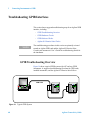
Troubleshooting GPIB Interfaces . . . . . . . . . . . . . . .
GPIB Troubleshooting Overview . . . . . . . . . . . . .
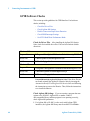
GPIB Hardware Checks . . . . . . . . . . . . . . . . . . . .
GPIB Software Checks . . . . . . . . . . . . . . . . . . . . .
Agilent IO Libraries Suite Checks . . . . . . . . . . . .
4
60
60
62
64
68
Connecting Instruments to USB . . . . . . . . . . . . . . . . . . . . . . . . . . . .71
USB Quick Start . . . . . . . . . . . . . . . . . . . . . . . . . . . . 72
Step 1: Install Agilent IO Libraries Suite on
Your PC . . . . . . . . . . . . . . . . . . . . . . . . . . . . . . . . 73
Step 2: Connect Instruments to USB . . . . . . . . . . . . . 73
USB Interface Overview . . . . . . . . . . . . . . . . . . . . 73
Connect USB Instruments . . . . . . . . . . . . . . . . . . . 74
Step 3: Run Agilent Connection Expert . . . . . . . . . . 75
Step 4: Communicate with Instruments . . . . . . . . . . . 79
Check Identification Parameters . . . . . . . . . . . . . . 79
Troubleshooting USB Interfaces . . . . . . . . . . . . . . . . 81
4
Agilent Connectivity Guide
USB Troubleshooting Overview . . . . . . . . . . . . . .
USB Hardware Checks . . . . . . . . . . . . . . . . . . . . .
USB Software Checks . . . . . . . . . . . . . . . . . . . . . .
Agilent IO Libraries Suite Checks . . . . . . . . . . . .
5
81
83
84
85
Connecting Instruments to LAN . . . . . . . . . . . . . . . . . . . . . . . . . . . .89
LAN Quick Start . . . . . . . . . . . . . . . . . . . . . . . . . . . . 90
Step 1: Install Agilent IO Libraries Suite on
Your PC . . . . . . . . . . . . . . . . . . . . . . . . . . . . . . . . 91
Step 2: Connect LAN Instruments . . . . . . . . . . . . . . .
Network Topologies . . . . . . . . . . . . . . . . . . . . . . .
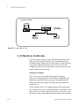
Directly Connect Instrument to Computer . . . . . .
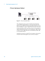
Private Instrument Subnet . . . . . . . . . . . . . . . . . . .
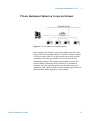
Private Instrument Subnet on Corporate Intranet .
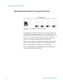
Open Instrument Subnet of Corporate Intranet . . .
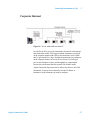
Corporate Intranet . . . . . . . . . . . . . . . . . . . . . . . . .
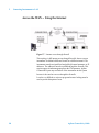
Across the WAN -- Using the Internet . . . . . . . . .
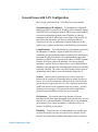
General Issues with LAN Configuration . . . . . . . .
91
91
93
94
95
96
97
98
99
Step 3: Run Agilent Connection Expert . . . . . . . . . 102
Add and Configure LAN Instruments . . . . . . . . . 103
Step 4: Communicate with Instruments . . . . . . . . . . 114
Communicate with Instruments Using Telnet . . . 117
Add a LAN interface . . . . . . . . . . . . . . . . . . . . . . 118
Troubleshooting LAN Interfaces . . . . . . . . . . . . . . .
LAN Troubleshooting . . . . . . . . . . . . . . . . . . . . .
Network Diagnostics . . . . . . . . . . . . . . . . . . . . . .
Agilent IO Libraries Suite Checks . . . . . . . . . . .
Agilent Connectivity Guide
122
122
130
130
5
6
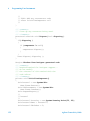
Programming Your Instruments . . . . . . . . . . . . . . . . . . . . . . . . . . .133
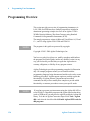
Programming Overview . . . . . . . . . . . . . . . . . . . . .
Obtaining Instrument Drivers . . . . . . . . . . . . . . .
Using Agilent IO Libraries Suite Sample Code .
Using VISA COM in Other
Visual Basic Projects . . . . . . . . . . . . . . . . . . .
134
135
136
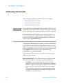
Addressing Instruments . . . . . . . . . . . . . . . . . . . . . .
Addressing Instruments via GPIB . . . . . . . . . . . .
Addressing Instruments via USB . . . . . . . . . . . .
Addressing Instruments via LAN . . . . . . . . . . . .
138
139
142
143
136
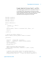
Sample Programs . . . . . . . . . . . . . . . . . . . . . . . . . . . 149
7
TCP/IP Network Basics . . . . . . . . . . . . . . . . . . . . . . . . . . . . . . . . . .159
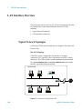
LAN Interface Overview . . . . . . . . . . . . . . . . . . . . . 160
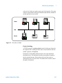
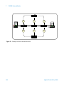
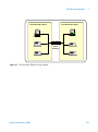
Typical Network Topologies . . . . . . . . . . . . . . . . 160
LAN Hardware Architecture . . . . . . . . . . . . . . . . 162
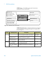
TCP/IP Protocols . . . . . . . . . . . . . . . . . . . . . . . . . . .
The TCP/IP Network Model . . . . . . . . . . . . . . . .
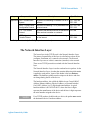
The Network Interface Layer . . . . . . . . . . . . . . .
The Internet Layer . . . . . . . . . . . . . . . . . . . . . . . .
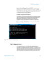
The Transport Layer . . . . . . . . . . . . . . . . . . . . . .
The Application Layer . . . . . . . . . . . . . . . . . . . .
165
165
167
168
169
171
IP Addressing . . . . . . . . . . . . . . . . . . . . . . . . . . . . .
IP Address Classes . . . . . . . . . . . . . . . . . . . . . . .
Subnets and Subnet Masks . . . . . . . . . . . . . . . . .
Local and Remote Networks . . . . . . . . . . . . . . . .
175
175
177
178
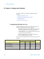
IP Address Configuration Methods . . . . . . . . . . . . . 180
Configuration Methods Overview . . . . . . . . . . . . 180
Dynamic Host Configuration Protocol (DHCP) . 181
6
Agilent Connectivity Guide
AutoIP/ZEROCONF . . . . . . . . . . . . . . . . . . . . . . 181
Duplicate IP Address Detection . . . . . . . . . . . . . 181
8
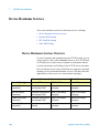
Device Hostname Services . . . . . . . . . . . . . . . . . . .
Device Hostname Services Overview . . . . . . . . .
Dynamic DNS Naming . . . . . . . . . . . . . . . . . . . .
RFC NetBIOS Naming . . . . . . . . . . . . . . . . . . . .
Static DNS Naming . . . . . . . . . . . . . . . . . . . . . . .
184
184
185
186
188
Configuring Your PC for LAN Operation . . . . . . . .
Checking PC Settings . . . . . . . . . . . . . . . . . . . . .
Installing Network Interface Cards . . . . . . . . . . .
Installing TCP/IP on Your PC . . . . . . . . . . . . . . .
Setting PC IP Address . . . . . . . . . . . . . . . . . . . . .
Setting PC Hostname . . . . . . . . . . . . . . . . . . . . .
189
189
190
190
193
194
Glossary . . . . . . . . . . . . . . . . . . . . . . . . . . . . . . . . . . . . . . . . . . . . . . .199
Agilent Connectivity Guide
7
8
Agilent Connectivity Guide
Agilent Connectivity Guide
1
Getting Started
This chapter includes:
• Using This Guide
• What is Agilent IO Libraries Suite?
• Agilent Web Resources
• Contacting Agilent
NOT E
Unless specifically noted, this version of the Agilent Connectivity
Guide is valid for Revisions 15.5 of the Agilent IO Libraries Suite
softwareand later including minor revisions of the software that do not
affect the technical accuracy of this guide
NOT E
This guide does not describe LAN networks that include a gateway,
such as the Agilent E5810A LAN/GPIB Gateway for Windows. See the
applicable gateway documentation for information on gateway systems.
Also, this guide does not provide a detailed description of LAN, USB,
or GPIB interfaces or TCP/IP networks. Consult standard reference
texts for this information.
If you need to contact Agilent, see “Contacting Agilent” on page 22 for
addresses.
Agilent Technologies
9
1
Getting Started
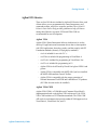
Using This Guide
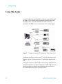
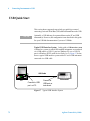
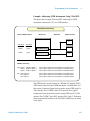
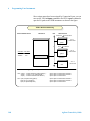
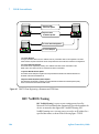
A typical complex test system includes a collection of instruments under
the control of a PC that has been programmed to perform testing and
reporting routines. Often, the communication between the test
instruments and the PC involve various forms of I/O; refer to Figure 1.
Figure 1
Example test system: PC, instruments, Three Types of I/O
Configuring interfaces to connect your PC to the test instruments can be
daunting. Agilent’s IO Libraries Suite v15 significantly simplifies this
task.
This Agilent Connectivity Guide with IO Libraries Suite Getting Started
describes in detail how to connect instruments to GPIB, USB, and LAN
interfaces and how to configure and troubleshoot these interfaces on
PCs with Windows Vista or XP operating systems.
10
Agilent Connectivity Guide
Getting Started
1
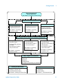
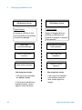
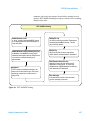
Step 1. Install Agilent IO
Libraries Suite v15.x
See Chapter 2, Installing IO Libraries Suite
Step 2. Connect Instruments, Install Drivers
GPIB
LAN
• Configure GPIB Network
• Install instrument drivers
USB
• Configure USB Network
• Install instrument drivers
See Chapter 3, Connecting
Instruments to GPIB
See Chapter 4, Connecting
Instruments to USB
• Select LAN Network
• Configure Instruments
• Install instrument drivers
See Chapter 5, Connecting
Instruments to LAN
Step 3. Configure Interfaces, Identify and Communicate with Instruments
• From Agilent Control icon, run
Connection Expert
• Configure GPIB Interface(s)
as needed
• Use Interactive IO utility to
verify communication
• From Agilent Control icon, run
Connection Expert
• Use Interactive IO utility to
verify communication
See Chapter 4, Connecting
Instruments to USB
• From Agilent Control icon, run
Connection Expert
• Right click on LAN interface to
add instruments
• Use Interactive IO utility to
verify communication
See Chapter 5, Connecting
Instruments to LAN
See Chapter 3, Connecting
Instruments to GPIB
Step 4. Program Your Instruments
• Using IVI-COM
• Using VISA
• Using SICL
• Troubleshooting
See Chapter 6, Programming Your Instruments
Installing IO Libraries Suite
• What is IO Libraries Suite
• Installing IO Libraries Suite
• IO Libraries Revision History
See Chapter 2, Installing IO Libraries Suite
Agilent Connectivity Guide
TCP/IP Network Basics
• TCP/IP Protocol
• IP Addressing
• Network Services
See Chapter 7, TCP/IP Network Basics
11
1
Getting Started
What is Agilent IO Libraries Suite?
Agilent IO Libraries Suite is a collection of libraries that give you the
ability to use your instruments from a test and measurement program,
and utilities that help you quickly and easily connect your instruments to
your PC.
Agilent IO Libraries Suite speeds your success with software utilities
that let you quickly connect your instruments to your PC, configure and
verify your connection, and get on with your job — whether that entails
programming instruments or using pre-existing application software.
For test and measurement programmers, the IO Libraries Suite brings
the power of the industry-standard VISA and VISA COM libraries, as
well as SICL and Agilent 488, to your programming experience.
12
NOT E
To access the Agilent IO Libraries Suite Online Help from the
Connection Expert window, click Help > Help Topics on the menu bar
or press the F1 key. To access the online Help without running
Connection Expert, click the IO Control icon(
) in the Windows
Notification area, click Documentation and then IO Libraries Suite
Help.
NOT E
To find out where the Agilent Connectivity Guide components listed
below have been installed on your system, click the IO Control icon
(
) in the Windows notification area, then click Installation
Information.
Agilent Connectivity Guide
Getting Started
1
Agilent IO Libraries
There are four IO Libraries included in Agilent IO Libraries Suite; each
of them allows you to programmatically control instruments, send
commands to them, and receive responses and data. The Agilent IO
Libraries Suite Online Help provides guidelines to help you choose
among these libraries; in general, VISA and VISA COM are
recommended for new development.
Agilent VISA
Agilent VISA (Virtual Instrument Software Architecture) is used to
develop I/O applications and instrument drivers that are interoperable
with VISA applications from other vendors, and that comply with IVI
Foundation standards (formerly VXIplug&play standards).
• visa.h is included for use with C/C++.
• visa32.bas is included for programming in Visual Basic 6.
• visa32.vb is included for programming in Visual Basic .Net.
• visa32.cs is included for programming in C#.
• Agilent VISA is the API used by DirectIO in Agilent VEE 8.0 and
greater.
• Agilent VISA is compatible with MATLAB if you have installed
the MATLAB Instrument Control Toolbox.
• Agilent VISA is compatible with the current generation of
National Instrument's LabVIEW and LabWindows/CVI products
(NI-VISA does not need to be installed).
Agilent VISA COM
Agilent VISA COM is a COM (Microsoft Common Object Model)
implementation based on the Agilent VISA architecture. Like VISA,
VISA COM conforms to IVI Foundation standards. The VISA COM
API works in environments that provide standard COM support such as
Visual Basic 6, Visual Basic.Net, and C#.
Agilent Connectivity Guide
13
1
Getting Started
Agilent SICL
Agilent SICL (Standard Instrument Control Library) is an I/O library
developed by Agilent that is portable across many instrument I/O
interfaces. Agilent does not recommend using SICL for new
development; instead use either VISA or VISA COM.
• sicl.h is included for use with C/C++.
• sicl32.bas is included for programming in Visual Basic 6.
Agilent 488
Agilent 488 is a GPIB I/O library provided for compatibility with
existing test and measurement programs developed using National
Instruments’ NI-488.2 or other similar libraries. Agilent 488 can be used
with any application development program that can access it including
LabVIEW, LabWindows/CVI, C/C++ and Visual Basic. Agilent does
not recommend using Agilent 488 (NI-488.2) for new development;
instead use either VISA or VISA COM.
Agilent IO Libraries Suite Utilities
Agilent’s IO Libraries Suite includes a number of utilities to help you
connect, configure, and troubleshoot your test system.
• Agilent Connection Expert
• Event Viewer (Microsoft Utility)
• Interactive IO
• ViFind32 (Debug Utility)
• VISA Assistant
• IO Monitor
• Agilent VISA Options
• Interactive LXI
Click the Agilent IO Control icon (
) in the Windows Notification
Area and select the appropriate utility.
NOT E
14
If the IO Control icon is not visible, you can display the icon by clicking
Start > Programs > Agilent Connectivity Guide > Utilities > IO
Control or, in Connection Expert, View > IO Control.
Agilent Connectivity Guide
Getting Started
1
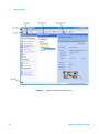
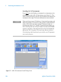
Agilent Connection Expert
Connection Expert is a software utility that helps you quickly get your
instruments connected to your PC and troubleshoot connectivity
problems. You can use Connection Expert to:
• Configure instrument I/O interfaces
• Automatically discover instruments that are connected to your PC or
to the local subnet of your local area network
• Specify connections to instruments that are on your local area
network beyond the local subnet
• Browse the structure and connections of your test system (including
your PC, instruments, and interfaces)
• Detect and troubleshoot connectivity problems in your test system
• Create programming aliases that you can use in place of addresses to
improve portability and readability of your test program
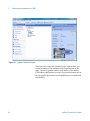
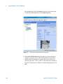
Connection Expert includes a task guide (the left pane of the utility’s
window) that provides shortcuts to common tasks and information.
Refer to Figure 2, “Agilent Connection Expert Screen,” on the next
page.
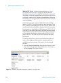
New to IO Libraries Suite v15 is the Agilent VISA Open Report.
Available from the I/O Configuration drop-down menu, this report
shows the combined view of your system from a VISA program
perspective. Conflicts or inconsistencies are listed and possible fixes are
also listed. This report does not cover VISA-COM behavior.
Agilent Connectivity Guide
15
1
Getting Started
Figure 2
16
Agilent Connection Expert Screen
Agilent Connectivity Guide
Getting Started
1
Agilent 488
Sets Agilent Connection Expert Options. Specifically Agilent VISA
options, Configuration Settings, 82357B options, and Agilent 488
options which enables Agilent GPIB cards to work in NI-488-2
compatible systems. Also available under Tools>Options.
Remote IO Server
The Remote IO Server software provides a way to connect via local area
network (Ethernet) to instruments that are physically connected to
another PC on the network. When the Remote IO Server is running on
one PC (the server), you can use instruments connected to that server
from other PCs (the clients) by using the Connection Expert to create
remote interfaces on the client PCs. See the Agilent IO Libraries Suite
Online Help for details.
VXI Resource Manager
The VXI Resource Manager is a software utility that initializes and
prepares a VXI system for use. If your system includes an E8491
IEEE-1394 PC Link to VXI interface, you can use the VXI Resource
Manager to determine whether your VXI system is properly configured.
The VXI Resource Manager runs when any of the following conditions
occurs:
• You start it from the Connection Expert’s Tools menu (select Tools >
VXI Resource Manager > Edit Resources, then click Run in the
resulting Resource Manager dialog box)
• You apply or cycle VXI mainframe power
• You press the E8491 Reset button
• You reboot your PC
In VXI systems with multiple E8491 interfaces, you can turn off
individual VXI mainframes without affecting other mainframes in the
system. When a mainframe is turned on, the VXI Resource Manager
reconfigures that mainframe.
Agilent Connectivity Guide
17
1
Getting Started
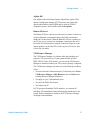
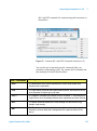
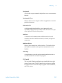
Interactive IO
Agilent Interactive IO is a software utility that allows you to interact
with an instrument by sending commands to the instrument and seeing
the instrument’s responses. You can use Interactive IO to:
• quickly verify connectivity to your instrument
• troubleshoot communication problems
• learn the instrument's command set
• rapidly prototype commands and check the instrument's responses
before writing code
With Interactive IO, you can choose from a menu of common
commands (listed in Table 1) or type in commands that are specific to
your instrument.
To start Interactive IO from within Connection Expert, click Tools >
Interactive IO from the Connection Expert menu bar or click Send
commands to this instrument on the task guide. You can also start
Interactive IO from the IO Control by clicking the IO icon in the
Windows notification area and then selecting Interactive IO.
Note that some commands (such as *TST?, instrument self-test) may
take longer than Interactive IO’s default time-out; you can modify the
time-out in the Interactive IO window by selecting Interact >
Options...
Figure 3
18
Interactive IO Screen
Agilent Connectivity Guide
Getting Started
Command
1
Description
*IDN?
The Identification query returns manufacturer, model,
serial number, and firmware level or equivalent.
*CLS
The Clear Status command clears status data structures, and
forces the device to the Operation Complete query idle
state.
*OPC?
The Operation Complete query places an ASCII character
“1” into the device’s Output Queue when all pending
selected device operations have been finished.
*RCL
The Recall command restores the current settings of a
device from a copy stored in local memory.
*RST
The Reset command performs a device reset, which sets the
device-specific functions to a known state that is
independent of the past-use history of the device.
*SAV
The Save command stores the current settings of the device
in local memory.
*STB?
The Read Status Byte query returns the status byte and
master Summary Status bit.
*TRG
The Trigger command signals the transition of the Device
Trigger (DT) function to the Device Trigger Active State
(DTAS).
*TST?
The Self-test query returns zero to indicate the test
completed with no errors. A return value not equal to zero
indicates the test is not completed or completed with errors.
Table 1
Interactive IO Common Commands
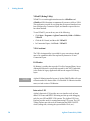
Event Viewer
Invokes the Microsoft Event Viewer, which can be useful in debugging
I/O programs
Agilent VISA Options
Provides commands to set the Logging and LockWait options for the
Agilent VISA library.
Agilent Connectivity Guide
19
1
Getting Started
ViFind32 (Debug Utility)
ViFind32 is a console application that uses the viFindRsrc and
viFindNext VISA functions to enumerate all resources visible to VISA.
This application is useful for verifying that all expected interfaces have
been configured by Connection Expert, and that the expected devices
have been attached.
To run ViFind32, you can do any one of the following:
• Click Start > Programs > Agilent Connectivity Guide > Utilities >
ViFind32
• Click the IO Control, and then click ViFind32
• In Connection Expert, click Tools > ViFind32
VISA Assistant
The VISA Assistant utility is provided for your convenience, though
most of its capabilities have been replaced by Interactive IO and
Connection Expert.
IO Monitor
IO Monitor is a utility that traces the I/O calls of targeted library layers.
Although IO Monitor is specifically targeted for the .NET Framework,
it also works for legacy applications that use the targeted I/O library
layers.
NOT E
Agilent IO Monitor installed as part of Agilent T&M ToolKit will cease
to function after IO Libraries Suite 15 is installed. IO Libraries installs a
newer, revised version of IO Monitor.
Interactive LXI
Agilent’s Interactive LXI provides two user interface tools to learn
about LXI Events and IEEE 1588 timing and also provide debugging
tools for your LXI and IEEE 1588 systems. The Agilent LXI Event
Explorer provides tools for creating/monitoring LXI events. The LXI
Timing Explorer provides tools for monitoring the IEEE 1588 PTP
clocks (setting time, selecting the system Master Clock, etc.).
20
Agilent Connectivity Guide
Getting Started
1
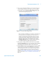
Visa Open Reports
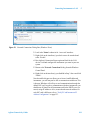
VISA Open Reports provide a quick “snapshot” of information about all
of the hardware interfaces (GPIB, USB, VXI, etc.) configured on your
PC.
Open the Report: From Agilent Connection Expert,
1 Select I/O Configuration from the menu bar.
2 Select VISA Open Report.
NOT E
Test and Measurement Interfaces (T&M), such as GPIB or VXI,
respond differently than standard computer interfaces (USB, LAN, etc.).
In general, for T&M interfaces all instruments on an interface either
pass or fail indicating the hardware interface is properly or improperly
configured. However, with computer interfaces, one instrument may fail
and all the others pass indicating the problem is with the actual
instrument.
For information on using the reports and the meaning of the various
messages, refer to the Agilent IO Libraries Suite 15 help file; search for
Visa Open Reports.
Agilent Connectivity Guide
21
1
Getting Started
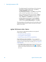
Agilent Web Resources
System Developer Center
Focus on what matters most: the performance, reliability and delivery of
your product. Agilent Open is a versatile combination of hardware, I/O,
and software tools that make it easy to create, enhance and maintain
systems. The System Developer Center provides application notes,
programming examples, instrument drivers, and much more:
http://www.home.agilent.com/find/systemcomponents
Test & Measurement Software and Connectivity Products
You can find product information on interface cards and converters at:
http://www.agilent.com/find/connectivity
You can find product information on I/O software at:
http://www.agilent.com/find/iosuite
Contacting Agilent
In the USA, you can reach Agilent Technologies at this telephone
number:
USA: 1-800-829-4444
Outside the USA, contact your country’s Agilent support organization.
A list of contact information for other countries is available on the
Agilent Web site:
http://www.agilent.com/find/assist
22
Agilent Connectivity Guide
Agilent Connectivity Guide
2
Installing Agilent I/O Libraries Suite
This chapter includes:
• System Requirements for Agilent IO Libraries Suite 15.5
• Installing the IO Libraries Suite Software
• Installation Troubleshooting
• Selecting Application Software
• Modifying, Repairing, or Removing IO Libraries Suite
• Keeping Your Software Up To Date
• Using Agilent VISA in Side-by-Side Mode
NOT E
This chapter assumes that you are installing Agilent IO Libraries Suite
from the Automation-Ready CD. If you are installing from the Web,
double-click the downloaded executable to extract files and launch the
setup program; then proceed with the software installation as
documented in this chapter.
Agilent Technologies
23
2
Installing Agilent I/O Libraries Suite
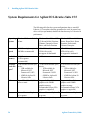
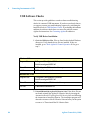
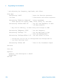
System Requirements for Agilent IO Libraries Suite 15.5
The following table lists the system configurations that we tested IO
Libraries 15.5 on and are therefore guaranteed to work. In general, any
x86 or x64 (except Itanium) should work but there may be a decrease in
performance.
Operating
System
Windows XP Service Pack 2
or later
Windows Vista SP1 and SP2
(32-bit and 64-bit), Business,
Ultimate, Enterprise, Home
Basic, and Home Premium
Windows 7 (32- and 64-bit)
Starter, Home Basic, Home
Premium, Professional,
Ultimate, Enterprise
Processor
Speed
600 MHz or higher required,
800 MHz recommended
1Ghz 32-bit (x86),
1GHz 64-bit (x64),
no support for Itanium64
1Ghz 32-bit (x86),
1GHz 64-bit (x64),
no support for Itanium64
Available
memory
256 MB minimum
(1 GB or greater
recommended)
1 GB minimum
1 GB minimum
Available 1.5 GB available hard disk space, 1.5 GB available hard disk space, 1.5 GB available hard disk space,
includes:
includes:
hard disk includes:
•
1GB
available
for
•
1GB
available
for
• 1GB available for
1
space
Microsoft .NET
Microsoft .NET
Microsoft .NET
Framework 2.0 SP2
Framework 2.0 SP1
Framework 2.0 SP1
• 65MB for Agilent IO
• 65MB for Agilent IO
• 65MB for Agilent IO
Libraries Suite
Libraries Suite
Libraries Suite
Video
Super VGA (800x600) 256
colors or more
Support for DirectX 9
graphics with 128MB
graphics memory
recommended (Super VGA
graphics is supported)
Support for DirectX 9
graphics with 128MB
graphics memory
recommended (Super VGA
graphics is supported)
Browser
Microsoft Internet Explorer
6.0 or greater
Microsoft Internet Explorer 7
or greater
Microsoft Internet Explorer 7
or greater
1 Because of the installation procedure, less memory may be required for operation than is required for installation.
24
Agilent Connectivity Guide
Installing Agilent I/O Libraries Suite
2
If possible, you should always use the current version of the Agilent IO
Libraries Suite. This version supports the newest interfaces and
operating systems, and has the most advanced features.
However, you may need an earlier version of the IO Libraries Suite to
support an older interface or operating system. For example, Agilent IO
Libraries Suite 15.1 is required for Windows 2000. If you need an
earlier version of Agilent IO Libraries, go to
http://www.agilent.com/find/iosuite to locate the version you need.
Agilent Connectivity Guide
25
2
Installing Agilent I/O Libraries Suite
Installing the IO Libraries Suite Software
NOT E
You must have Administrator privileges to install Agilent IO Libraries Suite
Connection Expert.
This section describes how to install Agilent IO Libraries Suite on your
PC. The process is as follows:
1 Verify that your PC meets the minimum system requirements. (See
“System Requirements for Agilent IO Libraries Suite 15.5” on
page 24.)
2 If you are upgrading to IO Libraries Suite from a previous version of
IO Libraries, you must remove the instruments and interfaces listed
below before you upgrade your software. This step is necessary in
order for these devices to obtain the correct drivers to work with
Agilent IO Libraries Suite.
a Disconnect any USB instruments from your PC.
b Disconnect any Agilent 82357 USB/GPIB interface converters
from your PC.
c Disconnect any Agilent E8491 IEEE 1394 PC Link to VXI
interfaces from your PC.
3 Close all other applications on your PC.
26
NOT E
If you install a PCI card in your computer at the same time you install
Agilent IO Libraries Suite 15, a possible conflict can occur. The “New
Hardware Found” dialog for the PCI card must be closed before
installing IO Libraries. Otherwise the IO Libraries installation will stop
until PCI card installation is complete.
NOT E
If you have NI software installed (such as NI MAX, etc.), then all NI
services must be stopped prior to installing IO Libraries.
Agilent Connectivity Guide
Installing Agilent I/O Libraries Suite
2
4 Insert the Automation-Ready CD with Agilent IO Libraries Suite into
the CD-ROM drive of your PC.
• Wait a few seconds for the auto-run window to appear.
• If the auto-run window does not appear automatically,
• Click Start > Run...
• Type:
<drive>:Autorun\IOLibraries.hta
where <drive> is your CD drive letter.
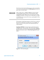
5 When the installation start-up window appears, click the “Click here
to install now” button once, and wait for the InstallShield Wizard to
appear.
Note: you also have the opportunity to watch a two-minute video
how easy it is to install, set-up and configure your interfaces and
instruments using Agilent IO Libraries Suite 15.5.
NOT E
If the IVI Shared Components and VISA Shared Components are
not already installed on your PC, Agilent IO Libraries Suite installs
them in the standard, default locations. If the IVI Shared Components
and VISA Shared Components are already installed, the Agilent IO
Libraries Suite installer will upgrade them to the latest version (if
necessary), using the same installation location used by the older
version. If this is a first-time installation, you will be able to select
installation locations for these components by choosing a Custom
Installation.
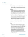
6 When the InstallShield Wizard appears, click Next > to begin the IO
Libraries Suite software installation.
7 Read the License Agreement(s). If you accept the terms, click the
radio button labeled I accept the terms of the license agreement
and then click Next > to continue.
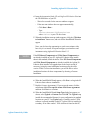
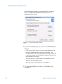
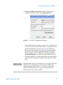
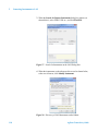
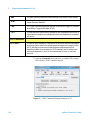
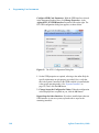
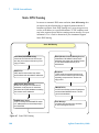
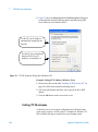
8 When the InstallShield Wizard Setup Type dialog box appears, as
shown, select Typical or Custom, then click OK. The Typical setup
installs the recommended features for your configuration in standard
locations on your PC. In a Typical setup, if another vendor’s VISA
software is already installed on this PC, Agilent VISA is installed as
secondary. If no other vendor’s VISA software is found on this PC,
Agilent Connectivity Guide
27
2
Installing Agilent I/O Libraries Suite
Agilent VISA is installed as primary. (See “Using Agilent VISA in
Side-by-Side Mode” on page 40.)
Figure 4
Choosing Setup Type
NOTE:
• If you accept the Typical Installation, click “Next” and proceed
to Step 12, Start Copying Files, on page 30.
• If you chose the Custom Installation radio button, click “Next”
and proceed with Step 10 below.
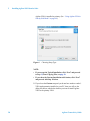
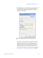
9 If you chose the Custom setup and you do not have another vendor’s
VISA implementation installed on your PC, then you will see the
dialog box below, which asks whether you want to install Agilent
VISA as the primary VISA.
28
Agilent Connectivity Guide
Installing Agilent I/O Libraries Suite
Figure 5
2
Agilent VISA as Primary VISA
If you do have another vendor’s VISA installed, you will see a
similar dialog box, but the check box will be not selected, indicating
that the default is to install Agilent VISA as secondary.
For details on this topic, see Using Agilent VISA in Side-by-Side
Mode on page 40.
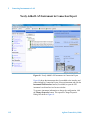
10 If you chose a Custom setup on 32-bit Windows, the next dialog
shows the location of:
• The Agilent IO Libraries Suite Destination Folder
• The VISA Destination Folder
• The IVI Shared Components Destination Folder
If VISA and IVI software is already installed, the VISA and IVI
destinations are greyed out. On a first-time installation on 32-bit
Windows, you can change all three destination folders.
Agilent Connectivity Guide
29
2
Installing Agilent I/O Libraries Suite
On 64-bit Windows systems, you cannot change the destination
folders. The Choose Destination Location dialog box is not
displayed on those systems..
Figure 6
Choose Destination Location
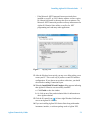
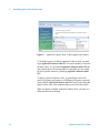
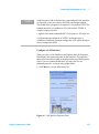
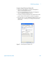
11 If you chose a Custom setup, you will now see the Select Features
dialog box.
• Click on any feature in the list to see the feature description and
the space requirements for the selected set of features. It is
recommended that you install the manuals and sample programs if
you plan to program with the Agilent IO Libraries; however, you
may omit them to save space.
• Select the check box for each feature to be installed. Clear the
check box for each feature to omit.
• When you are done selecting features, click Next >.
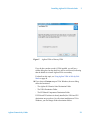
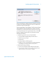
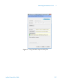
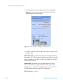
12 The Start Copying Files dialog appears; click Install to begin
copying files.
30
Agilent Connectivity Guide
Installing Agilent I/O Libraries Suite
2
• If the Microsoft .NET Framework has not previously been
installed on your PC, or if IO Libraries requires a newer version,
IO Libraries will install it; this may take up to ten minutes. The
Microsoft .NET Framework provides necessary infrastructure for
Agilent IO Libraries Suite utilities, as well as for .NET
programming tools and many other applications.
Figure 7
Copying Files
13 After the files have been copied, you may see a dialog asking you to
restart your PC. This occurs only if you have certain I/O hardware
configurations. If you choose not to reboot at this time, you should
reboot before running Connection Expert.
14 When the InstallShield Wizard Complete dialog appears indicating
that Agilent IO Libraries was successfully installed:
a Click Finish to close the window
b Or click on one of the product/solution links for information on
other Agilent solutions.
15 Click the IO control icon ( ) in lower right Windows Notification
area to run Agilent IO Libraries.
16 If you are installing Agilent IO Libraries Suite along with another
instrument, interface, or software package such as Agilent VEE,
Agilent Connectivity Guide
31
2
Installing Agilent I/O Libraries Suite
there may be another CD with additional software (drivers, sample
programs, etc.). If you want to install this additional software,
• Insert the CD into the CD drive on your PC.
• Follow the instructions that came with the CD or the hardware or
software product.
17 Re-connect any USB instruments or E8491 IEEE-1394 FireWire to
VXI interfaces that you may have disconnected in step 2. Install any
new hardware.
18 If Connection Expert is already running, click the Refresh All button
to identify any hardware you have just installed or re-connected.
If Connection Expert is not already running, run it now to verify your
I/O configuration: In the Windows Notification area, click the IO
icon ( ), then click Agilent Connection Expert.
a Locate your interfaces and instruments in the Explorer Pane.
Click on them to see their properties (displayed in the right-hand
pane). Observe their state, also displayed in the right-hand pane: if
communication to the interface or instrument has been
successfully established, it will be in the Verified state, denoted by
a green check mark.
b Change the default I/O configuration (if necessary) by clicking
Change Properties... in the property pane of the interface or
instrument you wish to configure.
NOT E
If you plan to program your GPIB instruments using the Agilent 488
API, or to run NI-488.2–compatible programs with Agilent interface
hardware (such as GPIB cards), you may need to enable the Agilent 488
library. To do this, click Tools > Agilent 488..., then select the check
box labeled Enable Agilent GPIB cards for 488 programs.
c If you would like to test your connections manually, select your
instrument, right-click and choose Send Commands To This
Instrument.
32
Agilent Connectivity Guide
Installing Agilent I/O Libraries Suite
2
Installation Troubleshooting
If you encounter problems while installing the IO Libraries Suite, the
following steps may help.
1 Close or Cancel all InstallShield Wizards and other Agilent IO
Libraries Suite windows. Exit any other applications on your system.
2 Browse to the autorun folder of your Automation-Ready CD and
double-click to run IOLibraries.hta. This restarts the
installation process.
3 If you see the standard InstallShield Wizard, step through the
installation process as described in this chapter.
4 If you see Modify, Repair, and Remove options, select Repair. This
will reinstall all installed features of IO Libraries Suite. If this does
not solve the problem, restart the installation again, select Remove,
and then reinstall the product.
Agilent Connectivity Guide
33
2
Installing Agilent I/O Libraries Suite
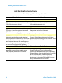
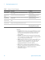
Selecting Application Software
This table gives guidelines for using additional I/O software.
When You Want to:
Use This Software:
Instrument Web Browser (Product Design or Product Characterization)
Remotely communicate with instruments from your
PC, but do not need to program the instruments.
(The IO Libraries are not required.)
Provides a “soft front panel” displayed on your Web
browser that you can use to control the instrument
(Web-enabled instruments only).
Agilent IntuiLink (Product Design or Product Characterization)
Remotely communicate with instruments from your
PC, but do not need to program the instruments
(The IO Libraries are required.)
Provides a “soft front panel” specific to an instrument
that you can use to control instruments.
IVI-COM Drivers (Product Characterization or Product Test)
IVI-COM drivers that implement standard
instrument-class interfaces provide syntactical
interchangeability; this means that you may be able
to replace an instrument in your test system with
another, similar instrument with fewer changes or
even no changes to your test program, depending
on your use of instrument-specific interfaces.
IVI-COM drivers are implemented as COM (Microsoft
Common Object Model) objects, and are therefore
optimized and recommended for use in Microsoft Visual
Studio and Visual Studio .NET.
VXIplug&play Drivers (Product Characterization or Product Test)
VXIplug&play drivers allow you to develop
application programs that are portable across
many computer platforms and I/O interfaces.
34
VXIplug&play drivers (also known as Plug&Play or
Universal Instrument Drivers) conform to a set of
system-level standards produced by the VXIplug&play
Systems Alliance. These standards apply to instrument
drivers, soft front panels, installation packages,
documentation, technical support and application
development environments. VXIplug&play drivers are
widely used and based on the VISA API.
Agilent Connectivity Guide
Installing Agilent I/O Libraries Suite
2
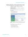
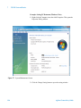
Modifying, Repairing, or Removing IO Libraries Suite
On Windows XP, click Start > Settings > Control Panel >
Add/Remove Programs.
On Windows Vista or Windows 7, click Start > Control Panel >
Programs and Features.
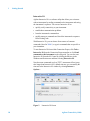
On 32-bit Windows systems, there are two entries for Agilent IO
Libraries Suite:
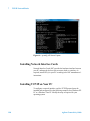
• Agilent IO Libraries Suite 15.5
• Agilent LXI Mdns Responder
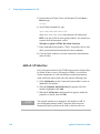
Figure 8
Agilent IO Libraries Suite 32-Bit Programs and Features
On 64-bit Windows systems, there are three entries:
• Agilent IO Libraries Suite 15.5
• Agilent IO Libraries Suite 64-bit
• Agilent LXI Mdns Responder 64bit
Agilent Connectivity Guide
35
2
Installing Agilent I/O Libraries Suite
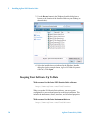
Figure 9
Agilent IO Libraries Suite 32-Bit Programs and Features
To Uninstall (remove) or Modify Agilent IO Libraries Suite, you must
select Agilent IO Libraries Suite 15.5. You cannot Modify or Uninstall
the other entries. If you Uninstall Agilent IO Libraries Suite 15.5, the
other related entries will automatically be uninstalled. You can modify
all of the optional features by Modifying Agilent IO Libraries Suite
15.5.
To Repair Agilent IO Libraries Suite, you must Repair each of the
entries in Programs and Features (or Add/Remove Programs) separately.
Always Repair Agilent IO Libraries Suite 15.5 last, because doing that
Repair restarts some of the programs that are part of the other entries.
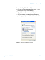
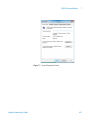
When you Repair or Modify Agilent IO Libraries Suite, you may see a
dialog similar to the following.
36
Agilent Connectivity Guide
Installing Agilent I/O Libraries Suite
2
If you see this dialog box, insert the Automation-Ready CD with Agilent
IO Libraries Suite into the CD-ROM drive of your PC. Windows will
use the files on the CD to make repairs.
If you are using Windows Vista or Windows 7 with User Access Control
(UAC) enabled, you may see this dialog box even if the CD is in the
CD-ROM drive. You will be able to browse to the files on the CD, but
you will get the dialog box above again and again when you click OK.
In order to complete the repair in this case, you must do one of the
following two procedures:
• Perform the repair with User Access Control disabled:
1 Close the Windows Installer dialog box (shown above).
2 Disable User Access Control.
3 Restart the PC.
4 Perform the Repair or Modify operation.
5 Enable User Access Control and follow any further instructions
from Windows. (You may be asked to restart your PC.)
• Run the installer from your desktop:
1 Do not close the Windows Installer dialog box shown above.
2 Copy the Installer folder from the Automation-Ready CD with
Agilent IO Libraries Suite to your PC’s desktop.
Agilent Connectivity Guide
37
2
Installing Agilent I/O Libraries Suite
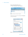
3 Use the Browse button in the Windows Installer dialog box to
browse to the location of the Installer folder on your desktop (as
shown below).
4 Select the installer that was indicated in the Windows Installer
dialog box (in the example shown, Agilent LXI Mdns Responder
64bit.msi). Click Open.
Keeping Your Software Up To Date
Web resource for the latest IO Libraries Suite software:
http://www.agilent.com/find/iosuite
When you update IO Libraries Suite software, your test system
configuration is preserved and passed on to the new installation. This
includes the instruments, aliases, interfaces, and all related properties.
Web resource for the latest instrument drivers:
http://www.agilent.com/find/drivers
38
Agilent Connectivity Guide
Installing Agilent I/O Libraries Suite
2
This Web site includes many types of instrument drivers, including
IVI-COM and VXIplug&play drivers.
NOT E
Agilent IO Libraries version 15.5 installs version 2.0.0 of the IVI
Shared Components (see http://www.ivifoundation.org/) and .NET
version 2.0 (with a Service Pack level that depends on your operating
system). If you are developing .NET programs, the development
environment you use must support .NET 2.0. For example, if you use
Visual Studio to develop C# or VB.NET applications, you must use
Visual Studio 2005 or higher. (MS Visual Studio 2003 does not
recognize .NET Framework 2.0, and as a result, Visual Studio 2003 may
not be used to develop .NET solutions with IO Libraries Suite 15.5.)
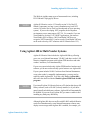
Using Agilent 488 in Multi-Vendor Systems
Agilent IO Libraries Suite includes the Agilent 488 library, allowing
you to use your National Instruments’ NI-488.2 and other vendors’ 488
libraries compatible programs with Agilent GPIB interfaces and other
vendors’ interfaces (even simultaneously).
If your test system includes only Agilent GPIB interface hardware and
software, you do not need to take any special action to use Agilent 488.
If your system includes NI-488.2 software from National Instruments,
or any other vendor’s compatible implementation, you may need to
explicitly enable Agilent 488. To do this, click Tools > Agilent 488...,
then select the check box labeled Enable Agilent GPIB cards for 488
programs.
If
NOT E
If you install Agilent IO Libraries Suite on a PC that has third-party 488
library software (such as NI-488.2) already installed, or if you subsequently install such third-party software, Agilent 488 will automatically
be disabled. If you want to use Agilent 488, you must re-enable it after
installing any third-party 488 library.
Although Agilent 488 does not conflict with NI-488.2 and both libraries
can be used simultaneously, some National Instruments software may
display error messages when Agilent 488 is enabled; for example, you
Agilent Connectivity Guide
39
2
Installing Agilent I/O Libraries Suite
may see the message Missing or Damaged GPIB-32.DLL when you
attempt to use National Instruments Measurement & Automation
Explorer to change the properties of an NI GPIB interface. If this
occurs:
1 Disable Agilent 488: in Connection Expert, click Tools > Agilent
488... and clear (deselect) the check box labeled Enable Agilent
GPIB cards for 488 programs.
2 Perform the operation that caused the error (such as changing the
properties of the NI interface).
3 Re-enable Agilent 488: in Connection Expert, click Tools > Agilent
488... and select the check box labeled Enable Agilent GPIB cards
for 488 programs.
(In a few cases, you may be prompted to restart your PC before you can
successfully enable or disable Agilent 488.)
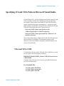
Using Agilent VISA in Side-by-Side Mode
NOT E
The following discussion applies specifically to 32-bit Windows
systems. For information on VISA architecture and interoperability on
64-bit Windows systems, see the Agilent IO Libraries Suite Online
Help.
Agilent IO Libraries Suite includes an implementation of VISA (Virtual
Instrument Software Architecture), one of three available application
programming instruments for instrument control. The VISA standard
requires that visa32.dll, the dynamic-link library that implements the
VISA interface, be installed in prescribed locations; therefore, only one
installed implementation (the primary implementation) can fully
comply with the standard at any one time. Because of this, you must
take special care if you want to use Agilent IO Libraries Suite alongside
any other implementation of VISA, such as National Instruments’
NI-VISA.
40
Agilent Connectivity Guide
Installing Agilent I/O Libraries Suite
2
When you have both Agilent VISA and another vendor's VISA installed
on the same system, you will need to decide whether to let your
programs use the primary VISA or whether to explicitly direct them to
use the Agilent VISA implementation.
NOT E
You do not need to install NI-VISA to use National Instruments GPIB
cards and devices. You can install National Instruments’ NI-488.2 as a
driver for these devices, and avoid the complications of side-by-side
operations.
Agilent IO Libraries Suite supports the option to install Agilent VISA in
side-by-side mode, which allows Agilent VISA to be used
simultaneously with another vendor's VISA implementation. In
side-by-side mode, Agilent VISA is installed only in a secondary
location and therefore does not overwrite another vendor's VISA if it is
present on the computer.
In general, non-Agilent VISA implementations do not support operation
as the secondary VISA (in side-by-side mode). This means that you
must operate Agilent VISA in side-by-side mode as the secondary
VISA, and the other vendor's VISA as primary.
About primary and secondary VISA:
• VISA programs normally use visa32.dll, which is installed in the
Windows system directory. This is the primary VISA, as defined
by the VISA standard.
• Agilent VISA is implemented in agvisa32.dll, which is also
installed in the Windows system directory.
• If Agilent VISA is installed as primary, the Agilent version of
visa32.dll is installed in the Windows system directory. It simply
forwards all VISA calls to agvisa32.dll.
• If you install Agilent VISA as primary, all files needed to support
side-by-side mode are also installed. This means that if you
subsequently install another vendor's VISA as primary, you can
still use Agilent VISA as secondary.
If Agilent VISA is installed in side-by-side mode (as the secondary
VISA):
Agilent Connectivity Guide
41
2
Installing Agilent I/O Libraries Suite
• agvisa32.dll is installed, but Agilent's visa32.dll is not. Thus, it
will not overwrite another vendor's visa32.dll residing in the
standard location.
• Agilent support files are not installed in the bin, include and lib
directories of the VISA path (e.g. c:\program files\visa\winnt),
since they would overwrite the other vendor's support files.
Copies of the Agilent versions of the VISA support files reside in
the agbin, include and lib subdirectories under <VISA path>\
agvisa. (These files are installed even when Agilent VISA is
primary.)
• The IO Control menu and the status bar at the bottom of the
Connection Expert window will contain a message indicating
whether Agilent VISA is installed as primary, installed as
secondary, or installed as primary but overwritten by another
vendor's VISA. In the latter case, Agilent VISA will operate
identically to a secondary installation.
VISA programs that are linked to the standard VISA DLL (e.g. C:\
WINDOWS\system32\visa32.dll) will use the primary VISA.
However, if a VISA program is linked with agvisa32.lib or
dynamically loads agvisa32.dll, it will always use Agilent VISA
(regardless of whether Agilent VISA is primary or secondary).
Addressing is identical regardless of whether you are using the primary
or secondary VISA in your program.
See the Agilent IO Libraries Suite Online Help for more information
about side-by-side VISA operation.
42
Agilent Connectivity Guide
Installing Agilent I/O Libraries Suite
2
Specifying IVI and VISA Paths in Microsoft Visual Studio
In Visual Studio (VS), you must add the directories that contain IVI and
VISA executables, include files, and libraries to the corresponding
search paths. If these paths do not include IVI and VISA directories,
various Visual Studio programs (including the C++ preprocessor, the
MIDL compiler, and the linker) may not be able to find needed IVI and
VISA files, and will generate errors. Typical errors are:
fatal error C1083: Cannot open type library file:
'IviDriverTypeLib.dll': No such file or directory
fatal error C1083: Cannot open include file: 'IviDriver.h': No
such file or directory
This section explains how to identify the IVI and VISA directories that
must be added to Visual Studio. For information on how to add
directories to the Visual Studio search paths, consult the help for your
version of Visual Studio.
VISA and VISA COM
To find the base directory where VISA and VISA-COM files are stored
on your system, look in the registry for the key:
HKLM\SOFTWARE\VXIPNP_Alliance\VXIPNP\CurrentVersion\
VXIPNPPATH
Using the value of this key as the visa_base_path add the following to
your VS search directories:
For Executable files:
<visa_base_path>\WinNT\bin
<visa_base_path>\agvisa\agbin
<visa_base_path>\VisaCom
Agilent Connectivity Guide
43
2
Installing Agilent I/O Libraries Suite
For Include files:
<visa_base_path>\WinNT\include
<visa_base_path>\WinNT\agvisa\include
For Library files:
<visa_base_path>\WinNT\lib\msc
<visa_base_path>\WinNT\agvisa\lib\msc
IVI Shared Components and IVI Drivers
To find the base directory where IVI files are stored on your system,
look in the registry for the key: HKLM\SOFTWARE\IVI\
IviStandardRootDir
Using the value of this key as the ivi_base_path add the following to
your VS search directories:
For Executable files:
<ivi_base_path>\bin
For Include files:
<ivi_base_path>\include
For Library files:
<ivi_base_path>\lib\msc
44
Agilent Connectivity Guide
Installing Agilent I/O Libraries Suite
NOT E
CAUTION
Agilent Connectivity Guide
2
Agilent IO Libraries version 15.5 installs version 2.0.0 of the IVI
Shared Components (see http://www.ivifoundation.org/) and .NET
version 2.0 (with a Service Pack level that depends on your operating
system). If you are developing .NET programs, the development
environment that you are using must support .NET 2.0. For example, if
you are using Visual Studio to develop C# or VB.NET applications, you
must use Visual Studio 2005 or higher. (MS Visual Studio 2003 does
not recognize .NET Framework 2.0, and as a result, Visual Studio 2003
may not be used to develop .NET solutions with IO Libraries Suite
15.5.)
Once you have installed version 2.x of the IVI Shared
Components (for example, by installing Agilent IO Libraries Suite
15.5), you will not be able to build IVI drivers and applications
developed with earlier versions. You will need to upgrade those
drivers/applications to the new IVI Shared Components (and to
build on Visual Studio 2005 or higher, or you will need to build
those drivers/applications on a different machine that does not
have version 2.x of the IVI Shared Components.
45
2
46
Installing Agilent I/O Libraries Suite
Agilent Connectivity Guide
Agilent Connectivity Guide
3
Connecting Instruments to GPIB
This chapter includes:
• GPIB Quick Start
• Step 1: Install Agilent IO Libraries Suite on Your PC
• Step 2: Connect Instruments to GPIB Card
• Step 3: Run Agilent Connection Expert
• Step 4: Communicate with Instruments
• Troubleshooting GPIB Interfaces
• GPIB Troubleshooting Overview
• GPIB Hardware Checks
• GPIB Software Checks
Agilent Technologies
47
3
Connecting Instruments to GPIB
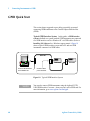
GPIB Quick Start
This section shows suggested steps to help you quickly get started
connecting GPIB instruments to the General Purpose Interface Bus
(GPIB).
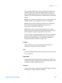
Typical GPIB Interface System In this guide, a GPIB interface
system is defined as a system in which GPIB instruments are connected
to a GPIB interface card in a Windows PC via GPIB cables. (Refer to
Installing I/O Software for a Windows support matrix.) Figure 10
shows a typical GPIB interface system with a PC and two GPIB
instruments connected via GPIB cables.
GPIB Cable
Instrument
Instrument
PC
Connect to GPIB Interface
Card installed in PC.
Connect to GPIB
port on instrument.
Figure 10 Typical GPIB Interface System
NOT E
48
You can also connect GPIB instruments using the Agilent 82357B
USB/GPIB Interface Converter -- then you won’t need a GPIB card. For
more information, go to www.agilent.com/find/gpib.
Agilent Connectivity Guide
Connecting Instruments to GPIB
3
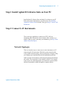
Step 1: Install Agilent IO Libraries Suite on Your PC
Before you connect your instruments to GPIB, install Agilent IO
Libraries Suite software on your PC. See Installing Agilent IO Libraries
Suite in Chapter 2 for details.
Step 2: Connect Instruments to GPIB Card
This step gives guidelines to connect GPIB instruments to a GPIB
Interface Card (such as an Agilent 82351 PCIe™-GPIB Interface Card)
installed in your PC by using GPIB cables. When you have made the
connections for your system, go to Step 3: Run Agilent Connection
Expert.
Install GPIB Cards in Your PC
Install GPIB interface cards (such as an Agilent 82351) in your PC,
following the manufacturers instructions.
NOT E
If you have not yet installed I/O software on your PC, go to Step 1:
Install Agilent IO Libraries Suite on Your PC and install the software
BEFORE you install GPIB Interface Cards in your PC.
NOT E
If your GPIB card is not an Agilent Technologies card, you may need to
install a driver from the card’s manufacturer.
Agilent Connectivity Guide
49
3
Connecting Instruments to GPIB
Connect GPIB Instruments
1 Review Connection Guidelines. The recommended method for
connecting a GPIB system is linear with the system controller
(PC) at one end of the system. However, a GPIB system can also
be connected together in a star or combination configuration. The
total number of devices on the system must be ≤14 and these
guidelines are followed:
• To minimize stress on connector mountings, stack no more
than three cable connector blocks on top of one another. The
GPIB connector screws should be finger-tightened only.
• Minimize cable length as much as possible. All system
devices must be powered on. Turning devices on or off while
a system is running may cause faulty operation.
• For data transfer rates <500 Kbytes/sec., the total allowed
length of all GPIB cables is ≤2 meters times the number of
devices connected together, up to a maximum of 20 meters.
• For data transfer rates > 500 Kbytes/sec., the total allowed
length of all GPIB cables is ≤1 meter times the number of
devices connected together, up to a maximum of 15 meters.
• The cable length between adjacent devices is not critical as
long as the system meets the overall restriction. GPIB bus
extenders are available that allow operation over much greater
distances.
• Connect GPIB Cables to the GPIB Interface Card. Connect a
separate GPIB cable to each installed GPIB Interface Card.
Tighten the GPIB connector screws finger-tight only. (The
screwdriver slots are for removal purposes only.) Two
example connections follow to connect a single GPIB
instrument or to connect multiple GPIB instruments.
50
Agilent Connectivity Guide
Connecting Instruments to GPIB
3
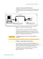
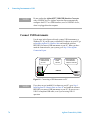
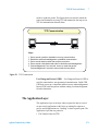
Example: Connecting a Single GPIB Instrument
The following figure shows connections from a single GPIB instrument
to the GPIB connector of an Agilent GPIB Interface Card installed in
your PC.
GPIB Cable
Instrument
GPIB Connector. Connect to GPIB
connector on 82350 installed in PC.
Figure 11
GPIB Connector. Connect to
GPIB port on GPIB Instrument.
Connecting a Single GPIB Instrument
You may want to record the primary GPIB address of the attached
instrument for future programming use. Or you can use Connection
Expert to create programming aliases that are meaningful to you. After
making the connections, reconnect the PC power cord and apply power
to the PC and to attached peripherals/instruments.
CAUTION
To avoid damage to the connectors, only finger-tighten the
connectors.
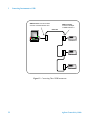
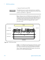
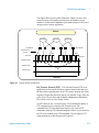
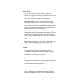
Example: Connecting Multiple GPIB Instruments
Figure 12 shows one way to connect three GPIB instruments to an
Agilent GPIB interface card. You may want to record the primary GPIB
address of each attached instrument for future programming use; or you
can use Connection Expert to create programming aliases that are
meaningful to you. After making the connections, reconnect the PC
power cord and apply power to the PC and attached
peripherals/instruments.
Agilent Connectivity Guide
51
3
Connecting Instruments to GPIB
GPIB Connector. Connect to GPIB
connector on 82350 Interface Card.
GPIB Connector.
Connect to GPIB port
on GPIB Instrument 1.
GPIB Cable
Instrument 1
PC
Instrument 2
Instrument 3
Figure 12 Connecting Three GPIB Instruments
52
Agilent Connectivity Guide
Connecting Instruments to GPIB
3
Step 3: Run Agilent Connection Expert
This step shows how to use Agilent Connection Expert to configure a
Windows operating system for a PC that has an Agilent GPIB Interface
Card (or equivalent) installed. The default configuration is done
automatically. Click Refresh All to update it at any time. This section
shows how to verify or change configuration parameters.
Configure GPIB Interface Cards
1 Apply Power. Apply power to the PC and to the installed GPIB
instruments. As Windows starts again, a Found New Hardware
Wizard may start.
2 Install Configuration Files. Click Next> to accept the defaults. (Make
sure that you have installed Agilent IO Libraries Suite first. You will
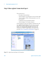
not need a CD.) Click Finish to complete the installation.
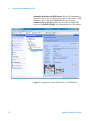
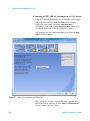
3 Open Connection Expert. Click the Agilent IO Control icon in the
Windows Notification area, and then click Agilent Connection Expert.
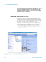
When the main screen appears, you will see a map of the system
connections in the Instrument I/O on this PC pane (also called
“Explorer Pane”). If you see your interface and instruments in the
Explorer Pane, you are ready to go!
NOT E
Agilent Connectivity Guide
For help with Connection Expert, refer to “Agilent Connection
Expert” on page 15 and the Agilent IO Libraries Suite help file. This
help file is available from the IO Control > Documentation menu.
53
3
Connecting Instruments to GPIB
Figure 13 Agilent Connection Expert
When you select a particular instrument in the Explorer Pane, you
see the parameters of the instrument in the Properties Pane on the
right – such as the product number, serial number, VISA address,
GPIB address, and firmware revisions. The green check mark icon at
the top signifies that a listener check and IDN query were performed
automatically.
54
Agilent Connectivity Guide
Connecting Instruments to GPIB
3
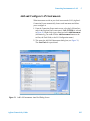
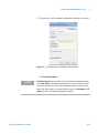
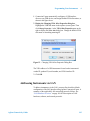
4 Configure GPIB Card Parameters. With the GPIB interface
selected in the Explorer Pane, click Change Properties....
Figure 14 The 82351 Configuration Dialog Box
Set the GPIB interface properties as required. Also, verify that this is
the System Controller for the GPIB to which it is attached (this is the
typical operating mode). (See the System Controller discussion
below.) If you plan to program your instruments using the Agilent
488 API, or to run NI-488.2–compatible programs with Agilent
interface hardware (such as GPIB cards), click the button labeled
Agilent 488 Properties... to enable the Agilent 488 library (if it is
not already enabled) or to change other properties as needed. Details
of each interface parameter are available in this dialog box’s online
Help.
NOT E
Agilent Connectivity Guide
Beginning with Agilent IO Libraries Suite 15.1, the Agilent 488 Board
Number always corresponds to the VISA Interface Number and it
cannot be modified. In IO Libraries 15.0 and earlier versions, the
Agilent 488 Board Number was a separate entity from the VISA
Interface Number and could be modified.
55
3
Connecting Instruments to GPIB
5 Change/Accept the Configuration Values. When the configuration
values displayed are acceptable to you, click the OK button.
Repeat Steps for Other Interfaces. If you have installed more than one
GPIB interface in your test system, repeat these steps for the remaining
interfaces.
System Controller
The System Controller setting determines whether this GPIB interface
controls which bus devices talk and which bus devices listen. If several
devices exist on a bus, be sure each has a unique GPIB bus address and
only one device is the system controller (it is usually the device installed
in the computer). Each GPIB interface has its own independent bus.
Thus, each interface may be a System Controller as long as it is not
chained together with other GPIB interfaces. However, two or more
System Controllers on the same bus will cause the bus to be inoperative.
Note that the Agilent 82357B USB/GPIB Interface Converter will
always be System Controller for its bus.
56
Agilent Connectivity Guide
Connecting Instruments to GPIB
3
Step 4: Communicate with Instruments
If your instruments show up in the Explorer Pane as verified,
communication has been established. This section shows how to further
verify instruments and connections using Interactive IO.
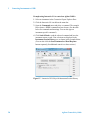
Communicating Using Interactive IO
Interactive IO is a utility within Agilent IO Libraries Suite that
communicates with instruments. It can be used to send and receive
strings to instruments, which support formatted I/O.
NOT E
Time-out Errors: If you are getting time-out errors when sending
commands and waiting for results, you can lengthen the time-out in the
Interact > Options menu, which is set at 5000 ms by default.
NOT E
When to Use VISA Assistant: VISA Assistant is still installed as part
of the Agilent IO Libraries Suite, but, for most users, it has been
replaced by the Interactive IO utility. Interactive IO provides a simpler,
more intuitive way to send commands to instruments and read the
results.
Some capabilities of VISA Assistant are not yet available in the
Interactive IO utility. These include:
• Memory I/O for VXI and GPIB-VXI interfaces
• Reading and writing of VISA attributes
• Configuration of VXIplug&play drivers
If you need these capabilities, you can start the VISA Assistant utility
by clicking the Agilent IO Control > VISA Assistant, or by clicking
Tools > VISA Assistant on the Connection Expert menu bar.
Agilent Connectivity Guide
57
3
Connecting Instruments to GPIB
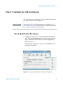
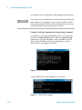
Example using Interactive IO to control an Agilent 34401A
1 Select an instrument in the Connection Expert Explorer Pane.
2 Click the Interactive IO icon below the menu bar.
3 Open the Commands menu and select a command. The example
below shows a *IDN? command has been chosen. (See the table
below for commands and meanings. You can also type an
instrument-specific command.)
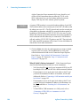
4 Click Send & Read to send the selected command and have the
instrument return a result. Your selections are displayed in the
Instrument Session History area, as shown in this example below.
(You can also click the Send Command and Read Response
buttons separately for additional control over these actions.)
Figure 15 Interactive IO Utility with Instrument Session History
58
Agilent Connectivity Guide
Connecting Instruments to GPIB
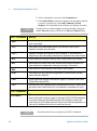
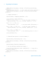
488.2 Commands
Meaning
*IDN?
The Identification query returns manufacturer, model, serial number, and
firmware level or equivalent.
*CLS
The Clear Status command clears status data structures, and forces the device
to the Operation Complete query idle state.
*OPC?
The Operation Complete query places an ASCII character “1” into the device’s
Output Queue when all pending selected device operations have been finished.
*RCL
The Recall command restores the current settings of a device from a copy
stored in local memory.
*RST
The Reset command performs a device reset, which sets the device-specific
functions to a known state that is independent of the past-use history of the
device.
*SAV
The Save command stores the current settings of the device in local memory.
*STB?
The Read Status Byte query allows the programmer to read the status byte and
master Summary Status bit.
*TRG
The Trigger command signals the transition of the Device Trigger (DT) function
to the Device Trigger Active State (DTAS).
*TST?
The Self-test query returns zero to indicate the test completed with no errors. A
return value not equal to zero indicates the test is not completed or completed
with errors.
3
SCPI Commands
SYST:ERR?
The error queue query message is a request for the next entry from the
instrument’s error/event queue. Items in this queue contain an integer in the
range [-32768 to 32767] denoting an error/event number and associated
descriptive text. Negative numbers are reserved by the SCPI standard; positive
numbers are instrument-dependent. A value of zero indicates that no error or
event has occurred.
Agilent Connectivity Guide
59
3
Connecting Instruments to GPIB
Troubleshooting GPIB Interfaces
This section shows suggested troubleshooting steps for an Agilent GPIB
interface, including:
• GPIB Troubleshooting Overview
• GPIB Hardware Checks
• GPIB Software Checks
• Agilent IO Libraries Suite Checks
NOT E
The troubleshooting procedures in this section are primarily oriented
toward an Agilent GPIB card and the Agilent IO Libraries Suite.
Consult your instrument’s User’s Guide for troubleshooting details for
the instrument.
GPIB Troubleshooting Overview
Figure 16 shows a typical GPIB system with a PC and two GPIB
instruments. A suggested troubleshooting flowchart for GPIB cards,
installed instruments, and the Agilent IO Libraries Suite follows.
GPIB Cable
PC
Instrument
Instrument
Figure 16 Typical GPIB System
60
Agilent Connectivity Guide
Connecting Instruments to GPIB
1
GPIB Hardware Checks
2
GPIB Software Checks
3
3
Agilent IO Libraries Suite
Checks
Typical Causes
Typical Causes
Typical Causes
Bad GPIB cables/connections
or power not ON for PC or
instruments
GPIB card drivers not installed
or GPIB card not properly
configured.
Agilent IO Libraries Suite not
installed or improper IO
Libraries Suite configuration
Check cables/
connections/power
Check for GPIB
driver files
Check IO Libraries Suite
Installation
Check Device Manager
Disable Agilent
Connection Expert
Auto-Detection
Check IO Control
Operation
Other hardware checks
Check BIOS/interrupt
settings
Install IO Libraries Suite (if
GPIB already installed)
Set 82350 Read/Write
performance mode
After doing these checks:
After doing these checks:
After doing these checks:
- If the cause is not identified,
see GPIB Software Checks
- If the cause is not identified,
see Agilent IO Libraries Suite
- If the cause is not identified
or the problem cannot be
fixed, contact Agilent for
support.
Checks
- If the cause is identified as an
82350 hardware problem,
contact Agilent to return the
82350.
Agilent Connectivity Guide
- If the cause is identified, but the
problem cannot be fixed, contact
Agilent for support.
61
3
Connecting Instruments to GPIB
GPIB Hardware Checks
This section gives guidelines to make hardware troubleshooting checks
for the GPIB card (such as an Agilent 82351 PCIe™-GPIB), including:
• Check Cables/Connections/Power.
• Check Device Manager
• If Sound Card Does Not Work
• If Data Transfers to Devices Fail
• If Connection Expert Finds an Agilent 82350 Card with Serial
Number ffffffff
Check Cables/Connections/Power.
Start your troubleshooting
sequence by performing the following hardware checks. If the hardware
checks do not solve the problem, see GPIB Software Checks.
NOT E
There are no user-serviceable parts for the GPIB Interface cards. If you
suspect a hardware failure for interface card, contact Agilent for
instructions to replace or repair the unit. See Contacting Agilent for
telephone numbers/web site address.
1 Check GPIB Cable Connections. Check all GPIB cables for good
connection to the GPIB connector on the interface card installed in
your PC and the GPIB cable connections between all connected
GPIB instruments. An improperly attached GPIB connector can
cause the bus to malfunction.
2 Check GPIB Cables for Damage. Check all GPIB cables for
cuts/damage and check for bent/misaligned/crushed connector pins.
Replace cables as required.
3 Disconnect/Reconnect GPIB Cables. If Steps 1 and 2 do not solve the
problem, try disconnecting and reconnecting (or replacing) GPIB
cables.
4 Check PC/Instrument Power-on. Verify that the PC and all connected
GPIB instruments are functional and are powered ON. Verify that
host computer is not in a Suspended power management state.
5 Reboot Your PC. If doing Steps 1, 2, 3 or 4 does not solve the
problem, reboot the PC. If this does not solve the problem, go to
Check Device Manager.
62
Agilent Connectivity Guide
Connecting Instruments to GPIB
3
Check Device Manager
You can use the Windows Device Manager
to reinstall the interface card as required. For example, open the Control
Panel.
Then, select System > Hardware > Device Manager. From Device
Manager, select the interface card and then Properties. Tab to Driver and
click Update Driver or Reinstall Driver. This allows the Windows Plug
and Play Manager to begin searching for a driver for the interface card.
Since Device Manager may have disabled the card device, click Enable
to restart the card. If this does not resolve the problem, go to GPIB
Software Checks.
If your sound card stops working after configuring interfaces, disable
the auto-detection process in Connection Expert. Click Tools >
Options... . Then de-select Automatic discovery or refresh of I/O
resources under the Configuration Settings tab.
If Data Transfers to Devices Fail If devices attached to your ISA
(82341) GPIB card are detected, but data transfers to those devices fail,
this is usually caused either by an IRQ conflict with another card or by
your system having no IRQs available for this card. If no IRQs are
available, the IRQ value shown in Connection Expert will be -1.
Try changing the IRQ setting to other values. You must reboot after
changing the value to test it. If none work, you will have to free up other
IRQs by disabling devices such as serial ports or sound cards.
If Connection Expert Finds an Agilent 82350 Card with Serial
Number ffffffff If Connection Expert reports finding an 82350 card
with serial number ffffffff, this is typically caused by a Windows system
configuration that results in failure to properly configure PCI cards. In
this case, upgrade your system BIOS to the latest version. Note that
even new computers tend to have new BIOS available.
Agilent Connectivity Guide
63
3
Connecting Instruments to GPIB
GPIB Software Checks
This section provides guidelines for GPIB Interface Card software
checks, including:
• Check for Driver Files
• Check Agilent 488 Settings
• Disable Connection Expert Auto-Detection
• Check BIOS/Interrupts Settings
• Set 82350 Read/Write Performance Mode
Check for Driver Files After installing the Agilent IO Libraries
Suite, check for installed driver files. Files are listed in their default
directories.
Windows 2000
Program Files
C:/Program Files/Agilent/IO Libraries Suite/drivers/ag350i32.dll
Driver Files
C:/Winnt/system32/drivers/agt82350.sys
.inf Files
C:/Winnt/inf/agtgpib.inf
Windows XP
Program Files
C:/Program Files/Agilent/IO Libraries Suite/drivers/ag350i31.dll
Driver Files
C:/Windows/system32/drivers/agt82350.sys
.inf Files
C:/Windows/inf/agtgpib.inf
Uninstall/Reinstall the Agilent IO Libraries Suite. If the driver files are
not found, uninstall the Agilent IO Libraries Suite by inserting the
Automation-Ready CD with Agilent IO Libraries Suite and following
the instructions to remove the libraries. Then, follow the instructions
to re-install the libraries.
Check Agilent 488 Settings If you are running a program that was
written to use NI-488.2, Agilent 488, or another vendor’s
488-compatible library, and that program is not operating correctly,
check Agilent 488 parameters:
1 For Agilent 488 or NI-488.2 code to work with Agilent GPIB
interfaces, the Agilent 488 library must be enabled. Click Tools >
64
Agilent Connectivity Guide
Connecting Instruments to GPIB
3
Agilent 488..., then select the check box labeled Enable Agilent
GPIB cards for 488 programs. This setting allows correct operation
of 488 programs with both Agilent and third-party GPIB interfaces
(even simultaneously).
If you receive errors from third-party tools (such as National
Instruments Measurement & Automation Explorer) when Agilent
488 is enabled, disable Agilent 488, use the third-party tool, then
re-enable Agilent 488.
2 Most NI-488.2 programs are written to expect the GPIB card at
board number 0 (zero). The default board numbers for Agilent GPIB
interfaces begin with zero, but for Agilent GPIB interfaces, the board
number is set independently from the VISA interface ID, so please
note that you may need to set the board number explicitly to work
with your program. To set the board number, select the GPIB
interface (the icon above your GPIB instruments) in Connection
Expert’s explorer view, then click the Agilent 488 Properties...
button in the detail (right) pane of the Connection Expert window
and set the board number in the resulting dialog box.
Disable Connection Expert Auto-Detection If your PC sound
card stops working after configuring interfaces, disable the
auto-detection process in Connection Expert, as the auto-detection
process in Connection Expert can cause sound and other cards to stop
responding. To disable the auto-detection process, click Tools >
Options... . Then de-select Automatic discovery or refresh of I/O
resources under the Configuration Settings tab.
Check BIOS/Interrupts Settings If Connection Expert reports
finding an 82350 card with Serial Number ffffffff, this is typically
caused by PCI cards not being configured properly. Try the following
steps. If these steps do not work, remove and re-install the 82350 and
then reconfigure the card.
1 Check BIOS Setting.
2 Upgrade your system BIOS to the latest version. New computers
oftentimes have newer BIOS’ available.
3 If your computer locks up or freezes after installing. This is typically
caused by interrupt conflicts with other drivers in the system. PCI
allows sharing of IRQs, but this also means the drivers for cards
which share an IRQ must be handling interrupt chaining properly.
Agilent Connectivity Guide
65
3
Connecting Instruments to GPIB
When the IRQ is asserted, the OS calls each ISR in turn until one of
them returns TRUE (meaning that it handled the interrupt). The
ISR’s responsibility is to correctly return TRUE if its device was
interrupting or FALSE if not. Drivers that return TRUE, even though
they did not service the interrupt, will cause problems. Try the
following steps:
• Upgrade the drivers for devices sharing an IRQ with Agilent,
including, but not limited to, your video drivers, your LAN
drivers, Agilent IDE and/or SCSI drivers, and your sound drivers.
4 Reconfigure Your PC. Configure your PC so as to not share IRQ lines.
Many PCI cards have bugs when sharing IRQ lines. You may or may
not be able to do this on all PCs. Many PCs can be configured using
the setup option when the PC is first booting.
5 Upgrade your system BIOS. New computers may have a newer BIOS
available. When installing a new system BIOS:
6 Make sure the BIOS Installed O/S setting is set correctly. This
determines what software will configure all the VXIplug&play cards
in your system. Either the BIOS or the O/S can perform the task of
querying all the cards to determine their resource needs, picking a
valid configuration for all these cards, and telling the cards what their
actual resource settings are.
• If the BIOS Installed O/S is set to Windows 95, Windows 98,
Windows 2000 or Running a PnP O/S, the BIOS will not perform
this task and will leave it to the O/S to do this. If the Installed O/S
is set to NOT PnP O/S, or Other, the BIOS will perform this task
and the system may not work properly.
Set 82350 Read/Write Performance Mode
The 82350 card read
and write calls use one of two modes:
• Polling. Bytes are transferred to/from the card, one at a time.
Polling mode is advantageous for transferring a small number of
bytes because the setup overhead is very low, but it does require
CPU involvement for each byte transferred.
• Interrupt. An entire buffer is transferred to/from the card without
CPU involvement. Interrupt mode is advantageous for
transferring large buffers because the higher per byte transfer rate
more than compensates for the relatively long interrupt setup
overhead.
66
Agilent Connectivity Guide
Connecting Instruments to GPIB
3
The default behavior of the 82350 driver is to use Polling mode for
transfers of 256 bytes or less and to use Interrupt mode for larger
transfers. You can modify this default behavior by doing the following:
VISA: The VISA function
viSetAttribute(vi, VI_ATTR_DMA_ALLOW_EN,
attrValue)
can be called to modify the read/write behavior for a VISA session. The
VI_ATTR_DMA_ALLOW_EN values allowed are:
• VI_TRUE (default value) Use Interrupt mode for transfer
requests larger than 256 bytes, otherwise, use Polling mode.
• VI_FALSE Use the Polling mode.
SICL: The SICL function
ihint(id, hint)
can be called to modify the read/write behavior for on a SICL session.
The hint values allowed are:
• I_HINT_DONTCARE (default value) Use Interrupt mode for
transfer requests larger than 256 bytes, otherwise, use Polling
mode.
• I_HINT_USEPOLL Use the Polling mode.
• I_HINT_IO Use the Interrupt mode.
Some additional factors to consider are:
• The settings discussed above are per session. This means you can
open multiple sessions to a device and set different transfer modes
for different sessions. The actual mode used will then depend on
which session you are using for the read/write calls.
• In both SICL (with hint = I_HINT_DONTCARE) and VISA
(with VI_ATTR_DMA_ALLOW_EN = VI_TRUE), the size of
the read request (as specified by bufsize in a SICL iread()
or count in a VISA viRead() function call) will determine the
mode used even if the number of bytes actually read is less.
• The default formatted I/O read buffer size is 4096 so when using
this default size, formatted reads in SICL (with hint =
I_HINT_DONTCARE) and VISA (with
VI_ATTR_DMA_ALLOW_EN = VI_TRUE) will use Interrupt
mode even when a small number of bytes are expected.
Agilent Connectivity Guide
67
3
Connecting Instruments to GPIB
• The default formatted IO write buffer size is 128 so when using
this default size, formatted writes in SICL (with hint =
I_HINT_DONTCARE) and VISA (with
VI_ATTR_DMA_ALLOW_EN = VI_TRUE) will used Polling
mode even when a large number of bytes are being sent.
• In SICL, Polling mode will always be used for the iread(),
ifread() and iscanf() regardless of the above settings,
when a termchr is set (itermchr() is not set to -1).
• In VISA, Polling mode will always be used for viRead(),
viBufRead() and viScanf() regardless of the above
settings, when VI_ATTR_TERM_CHAR_EN = VI_TRUE.
The crossover point at which the Interrupt mode becomes faster then the
Polling mode depends on the CPU speed, with a faster CPU having a
higher crossover point.
Agilent IO Libraries Suite Checks
This section gives troubleshooting guidelines for the Agilent IO
Libraries Suite, including:
• Check IO Libraries Suite Installation
• Check Agilent IO Control Operation
• Install IO Libraries Suite (if 82350 was Installed First)
Check IO Libraries Suite Installation Start your Agilent IO
Libraries Suite troubleshooting sequence by verifying IO Libraries Suite
installation. If the IO Libraries Suite is installed, go to Check Agilent IO
Control Operation.
1 Check Agilent IO Libraries Suite Version. If Agilent IO Libraries Suite
version 15.0 or later is installed, a blue IO icon (
) is normally
displayed in the Windows notification area (on the lower right side of
the screen).
68
Agilent Connectivity Guide
Connecting Instruments to GPIB
3
• If the IO icon is displayed, click the icon and click About Agilent
IO Control to display the version. Version 15 or greater must be
installed. (The next version of the IO Libraries after “M”
discontinued this naming convention, and uses IO Libraries Suite
14.0 instead to designate the version immediately following
M.01.01.)
• If the IO icon is not displayed, a version may still be installed. To
check this, click Start | Programs and look for the Agilent IO
Libraries Suite program group.
• If this group is displayed, click Agilent IO Libraries Suite >
Utilities > IO Control to display the IO icon. Then, click the icon
and click About Agilent IO Control to display the installed version
(must be M.01.00 or greater).
• If neither the IO icon nor the Agilent IO Libraries Suite program
group is displayed, no Agilent IO Libraries Suite are installed.
2 Install Agilent IO Libraries Suite (as Required). If Agilent IO Libraries
Suite v15 or greater is not installed on your PC, install the IO
Libraries Suite. Otherwise, go to Check Agilent IO Control
Operation.
Check Agilent IO Control Operation
When the Agilent IO
Libraries Suite was installed, the Agilent IO Control was started. When
the IO Control is active, it is displayed as a blue circled IO icon on the
Windows tasteable. If the Agilent IO Control is deactivated, I/O
applications that are running with the GPIB interface card may be
unable to open sessions or to communicate with the card and devices.
By default, the Agilent IO Control is always active after the Agilent IO
Libraries Suite is installed and the blue IO icon is displayed. However,
the IO Control may be active even though the blue IO icon is not
displayed. There are two ways that the blue IO icon can be hidden:
• Clicking Hide Agilent IO Control. Clicking the blue IO icon and
then clicking Hide Agilent IO Control hides the IO icon, but does
not deactivate the Agilent IO Control.
• Clicking Exit. Clicking the blue IO icon and then clicking Exit
causes a dialog box to appear that asks you if you want to
terminate the Agilent IO Control. Clicking Yes hides the blue IO
icon and deactivates the Agilent IO Control.
Agilent Connectivity Guide
69
3
Connecting Instruments to GPIB
If the blue IO icon is not displayed, either the blue IO icon display has
been turned off and/or the Agilent IO Control (and associated
iprocsvr.exe) is not active. In this case, click Start > Programs > Agilent
IO Libraries and then click Agilent IO Control to re-start the Agilent IO
Control and to display the blue IO icon.
Install IO Libraries Suite (if 82350 was Installed First)
NOT E
When you install the Agilent IO Libraries Suite, drivers for your 82350
GPIB card will be installed automatically. You should not need to take
additional steps to install drivers. The information in this section is
provided to assist you in case you have problems with your GPIB card
and drivers.
• If you installed the 82350 GPIB card before installing the Agilent
IO Libraries Suite software, use the applicable step for your
operating system to install the Agilent IO Libraries Suite. After
the drivers for all new cards are installed, you can run Setup from
the Automation-Ready CD with Agilent IO Libraries Suite to
install and configure the Agilent IO Libraries Suite.
70
NOT E
On older operating systems, you may be asked to insert the 'HP I/O
Libraries' CD. You should use the CD that contains the Agilent IO
Libraries Suite in this case. The card will be identified as a
Hewlett-Packard card. This is necessary for backward compatibility.
NOT E
On Windows 2000, the Found New Hardware Wizard will identify this
card as a PCI Simple Communications Controller. The driver is typically
located in the \Windows 2000 directory on the instrument CD.
Agilent Connectivity Guide
Agilent Connectivity Guide
4
Connecting Instruments to USB
This chapter includes:
• USB Quick Start
• Step 1: Install Agilent IO Libraries Suite on Your PC
• Step 2: Connect Instruments to USB
• Step 3: Run Agilent Connection Expert
• Step 4: Communicate with Instruments
• Troubleshooting USB Interfaces
• USB Troubleshooting Overview
• USB Hardware Checks
• USB Software Checks
Agilent Technologies
71
4
Connecting Instruments to USB
USB Quick Start
This section shows suggested steps to help you quickly get started
connecting Universal Serial Bus (USB) enabled instruments to the USB.
NOT E
Optionally, a USB hub may be connected between the PC and USB
instrument(s). However, this configuration is not described in this guide.
See your USB hub documentation if you use a USB hub.
Typical USB Interface System In this guide, a USB interface system
is defined as a system in which USB-enabled instruments are connected
via a USB cable to a USB 1.1 port in a Windows PC or to a USB 2.0
port in a Windows XP PC (with Service Packs 1 or 2). Figure 17, below,
shows a typical USB interface system with a PC and a USB instrument
connected via a USB cable.
USB Cable
PC
Connect to USB
port on PC.
Connect to
USB port on
instrument.
Instrument
Figure 17 Typical USB Interface System
72
Agilent Connectivity Guide
Connecting Instruments to USB
4
Step 1: Install Agilent IO Libraries Suite on Your PC
Install Agilent IO Libraries Suite and other I/O software on your PC
before you connect instruments to USB. See Installing Agilent I/O
Libraries Suite in Chapter 2 for details.
Step 2: Connect Instruments to USB
This step provides a USB interface overview, shows how to connect
USB Instruments using the USB ports on your PC, or by using the
Agilent 82357B USB/GPIB Interface Converter.
USB Interface Overview
When a USB device that implements the USBTMC (Universal Serial
Bus, Test and Measurement Class) or USBTMC-USB488 protocol is
plugged into the computer, the Agilent IO Libraries Suite automatically
detects the device. It is important to note that only USBTMC and
USBTMC-USB488 devices are recognized by the IO Libraries Suite.
Other USB devices such as printers, scanners, and storage devices are
not recognized and cannot be programmed with the Agilent IO Libraries
Suite. “USB instruments” in the remainder of this chapter refers to
devices that implement the USBTMC or USBTMC-USB488 protocol.
Connecting an Instrument via USB or Converter. The Universal
Serial Bus (USB) is a quick and easy way to connect instruments to PCs
on a benchtop. Some newer instruments have USB interfaces built in;
for those that do not, you can use the Agilent 82357B USB/GPIB
Interface Converter to connect GPIB instruments to a USB port on
your PC. You can use USB to connect a single instrument to a PC; or,
with the 82357B, you can connect up to 14 GPIB instruments.
Agilent Connectivity Guide
73
4
Connecting Instruments to USB
NOT E
Do not confuse the Agilent 82357 USB/GPIB Interface Converter
with a USBTMC device. Agilent Connection Expert automatically
configures the 82357 as a GPIB interface, not as a USBTMC device,
when it is plugged into the computer.
Connect USB Instruments
Use the steps in this figure to directly connect USB instruments to a
Windows PC. If you have not yet installed I/O software on your PC, go
to Installing Agilent I/O Libraries Suite and install the software
BEFORE you connect USB instruments to your PC. When you have
made the connections for your system, go to Step 3: Run Agilent
Connection Expert.
a Connect PC end of
USB cable to USB
port on PC
b Apply power
to USB
instrument
c Connect instrument
end of USB cable to
USB port on instrument
USB Cable
Instrument
PC
Figure 18 Connecting a USB Instrument to a PC
NOT E
74
If you have not yet installed I/O software on your PC, go to Step 1:
Install Agilent IO Libraries Suite on Your PC and install the software
BEFORE you connect USB instruments to your PC. Be sure to use a
USB 2.0-compliant USB cable, even if you are using USB 1.1
operation.
Agilent Connectivity Guide
Connecting Instruments to USB
4
Step 3: Run Agilent Connection Expert
This step provides an overview of how Connection Expert automatically
identifies USB instruments, and how you can assign VISA aliases, or
programming aliases, to address those instruments in a more convenient
way.
Click the Agilent IO Control icon in the Windows Notification area, and
then click Agilent Connection Expert. When the main screen appears,
you will see a map of the system connections in the Instrument I/O on
this PC pane (also called “Explorer Pane”). If you see your interface
and instruments in the Explorer Pane, you are ready to go!
NOT E
Agilent Connectivity Guide
For help with Agilent Connection Expert, refer to “Agilent Connection
Expert” on page 15 of this manual and the Agilent IO Libraries Suite
help file. This help file is available from the IO Control Documentation
menu.
75
4
Connecting Instruments to USB
Automatic Identification of USB Devices. When a USB instrument is
plugged into the PC, the IO Libraries Suite adds a USB interface, a USB
instrument, and a VISA alias (UsbDevice1, in this case) to the
Instrument I/O on this PC explorer tree. Note that the USB/GPIB
converter, USB/GPIB (GPIB0), looks different than the USB interface.
Figure 19 Appearance of the USB Converter vs. USB Interface
76
Agilent Connectivity Guide
Connecting Instruments to USB
4
Both a listener check and an identification query are done automatically,
as you can see on the right side in the USB Instrument pane next to the
green-white check mark symbol.
NOT E
When you apply power, a Found New Hardware wizard may appear
from the Windows operating system. Just step through the wizard
clicking Next. (You don’t need to insert a CD, since you have already
installed the I/O software.) You may see two wizards when you connect
a USB/GPIB interface converter. Don’t worry; step through both. Then
return to this section.
The instrument’s identification parameters can also be seen, such as the
IDN string, the manufacturer, the model code, the serial number, the
firmware revision as well as pictures of the instrument and PC rear
connection panels.
Assigning a VISA Alias. Connection Expert automatically assigns a
default alias name. You can modify a VISA alias by right-clicking on
the USB instrument in the Instrument IO pane and selecting Add VISA
alias from the drop-down menu. A VISA Alias Properties dialog box
appears.
Figure 20 VISA Alias Dialog Box
Agilent Connectivity Guide
77
4
Connecting Instruments to USB
You can change this VISA alias name to one of your own choosing
before clicking OK.
NOT E
A VISA alias is a name of your choosing, which you assign to a device
and use in your programs. Once assigned, the alias is a synonym for the
device's VISA address, so you can use it to open a VISA session (using
the viOpen function) and to get resource information (using
viParseRsrc or viParseRsrcEx).
Using VISA aliases in your programs, rather than VISA addresses,
provides two significant advantages:
• Portability. If you program using aliases, you can run your program
on a new test system, whose instruments are at different addresses,
simply by using Connection Expert to create the same aliases on the
new system as you created on your development system. Similarly,
you can move or replace instruments without changing or
recompiling test code, simply by changing the alias definitions in
Connection Expert.
• Readability. Your programs will be much easier to read and
understand if, for example, your multimeter is called “myDMM”
instead of “GPIB2::14::8::INSTR”. This is particularly important in
the case of USB instruments, whose VISA addresses are typically
long and cumbersome, containing the instrument's serial number
among other information.
78
Agilent Connectivity Guide
Connecting Instruments to USB
4
Step 4: Communicate with Instruments
This step shows how to use Interactive IO to send 488.2 commands to
your USB instruments and read responses.
NOT E
Communication with installed instruments was established in Step 2:
Connect Instruments to USB. Therefore, this is an optional step you can
use to verify communication with instruments.
Check Identification Parameters
1 Highlight the USB instrument in the Instrument I/O on this PC
pane. Then click the Interactive IO icon on the tool bar. (If you are
using a USB/GPIB converter, then you would be highlighting a
GPIB instrument.)
The Interactive IO dialog box appears. The Commands menu is
selected, as shown below.
Figure 21 Interactive IO with 488.2 Commands Displayed
Agilent Connectivity Guide
79
4
Connecting Instruments to USB
2 Select a command, or enter one in the Command area.
3 Click Send & Read to send the command to the instrument and read
a response. Alternatively, click Send Command and Read
Response. The Instrument Session History area displays the results.
NOT E
If a time-out occurs when sending/receiving commands, change the
default Time-out setting of 5000ms in the Interact>Options dialog.
488.2 Commands
Meaning
*IDN?
Identification query returns manufacturer, model, serial number, and firmware
level or equivalent.
*CLS
Clear Status clears status data structures, and forces the device to the
Operation Complete query idle state.
*OPC?
Operation Complete query places an ASCII character “1” into the device’s
Output Queue when all pending selected device operations have been finished.
*RCL
Recall restores the settings of a device from a copy stored in local memory.
*RST
Reset performs a device reset, which sets the device-specific functions to a
known state that is independent of the past-use history of the device.
*SAV
Save stores the current settings of the device in local memory.
*STB?
Read Status Byte query allows the programmer to read the status byte and
master Summary Status bit.
*TRG
Trigger signals the transition of the Device Trigger (DT) function to the Device
Trigger Active State (DTAS).
*TST?
Self-test returns zero indicating the test completed with no errors. A return value
not equal to zero indicates the test is not completed or completed with errors.
SCPI Commands
SYST:ERR?
This message requests the next entry from the instrument’s error/event queue.
Items in this queue contain an integer in the range [-32768, 32767] denoting an
error/event number and associated descriptive text. Negative numbers are
reserved by the SCPI standard; positive numbers are instrument-dependent. A
value of zero indicates that no error or event has occurred.
NOT E
80
Some instruments do not recognize any/all 488.2 commands.
Agilent Connectivity Guide
Connecting Instruments to USB
4
Troubleshooting USB Interfaces
This section shows suggested troubleshooting steps for Universal Serial
Bus (USB) interfaces, including:
• USB Troubleshooting Overview
• USB Hardware Checks
• USB Software Checks
NOT E
The troubleshooting procedures in this section are primarily oriented
toward USB instruments and the Agilent IO Libraries Suite. Consult
your instrument’s User’s Guide for troubleshooting details for the
instrument.
USB Troubleshooting Overview
This figure shows a typical USB interface with a PC and a USB
instrument. A suggested troubleshooting flowchart for USB instruments
and the Agilent IO Libraries Suite follows. We suggest you start at USB
Hardware Checks and then go to USB Software Checks, as required.
Agilent Connectivity Guide
81
4
Connecting Instruments to USB
USB Hardware Checks
Typical Causes
Typical Causes
No power on USB bus or hub
or device turned off by Windows
Plug and Play Manager.
Agilent IO Libraries Suite not
installed or USB drivers not
installed or improper IO Libraries
Suite operation.
Check cable
connections/damage
Verify Agilent IO Libraries
Suite installation
Check PC/instrument
functions
Verify USB driver
installation
Check device manager
Check IO Control
operation
After doing these checks:
After doing these checks:
- If the cause is not identified,
see Software Checks.
- If the cause is not identified
or the problem cannot be
fixed, contact Agilent for
support.
- If the cause is identified as a
hardware problem, contact
Agilent to return the device.
82
USB Software Checks
Agilent Connectivity Guide
Connecting Instruments to USB
4
USB Hardware Checks
This section gives guidelines to make hardware troubleshooting checks
for connected USB instruments. Start your troubleshooting sequence by
performing the following hardware checks. If performing the hardware
checks do not correct the problem, go to USB Software Checks.
Check Cable Connections/Damage
Check all USB cables for
good connection to the USB connector on your PC, to all USB hubs (if
installed) and the USB cable connections to connected USB
instruments. An improperly attached USB connector can cause the
interface to malfunction.
Check all USB cables for cuts/damage and check for
bent/misaligned/crushed connector pins. Replace cables as required. If
these actions do not solve the problem, try disconnecting and
reconnecting (or replacing) USB cables. If the cable checks do not solve
the problem, go to Check PC/Instrument Functions.
Check PC/Instrument Functions Verify that all USB hubs, and all
connected USB instruments are functional and are powered ON. Verify
that host computer is not in a Suspended power management state. If
these actions do not solve the problem, reboot the PC. If this does not
solve the problem, go to Check Device Manager.
Check Device Manager
You can use the Windows Device Manager
to reinstall the USB instrument driver, as required. For example, with
Windows XP, go to Control Panel. Then, select System > Hardware >
Device Manager. From Device Manager, select the USB Test and
Measurement Device and then right click for Properties.
Tab to Driver and click Reinstall Driver. This will allow the Windows
Plug and Play Manager to begin searching for a driver for the
instrument. Since Device Manager may have disabled the instrument,
click Enable to restart the instrument.
NOT E
Agilent Connectivity Guide
Windows may place a misbehaving USB device in an “Unknown
device” category. To see if this has happened, change the View in Device
Manager by selecting View > Show Hidden Devices. Next, right-click the
Universal Serial Bus Controllers Unknown device and select Uninstall.
Then, select Device Manager > Action > Scan for hardware changes.
83
4
Connecting Instruments to USB
USB Software Checks
This section provides guidelines to make software troubleshooting
checks for connected USB instruments. If you have not already done so,
we suggest you start your troubleshooting sequence by performing the
hardware checks in USB Hardware Checks. If performing the hardware
and then the software checks does not correct the problem, contact
Agilent for instructions. See Contacting Agilent for addresses.
Verify USB Driver Installation
1 Check for USB Driver Files. Files are listed in their default Windows
directories. Verify that the driver files are installed. If they are
installed, go to Check Agilent IO Control Operation. If not, go to
step 2.
Windows 2000
Program Files
C:/Program Files/Agilent/IO Libraries
Suite/drivers/agusb48832.dll
Driver Files
C:/Winnt/system32/drivers/ausbtmc.sys
.inf Files
C:/Winnt/inf/ausbtmc.inf
Windows XP / Vista
Program Files
C:/Program Files/Agilent/IO Libraries
Suite/drivers/agusb48831.dll
Driver Files
C:/Windows/system32/drivers/ausbtmc.sys
.inf Files
C:/Windows/inf/ausbtmc.inf
2 Uninstall/Reinstall the Agilent IO Libraries Suite. If the driver files are
not found, uninstall the Agilent IO Libraries Suite by inserting the
Automation-Ready CD with Agilent IO Libraries Suite and following
the instructions to install the libraries. The installation program will
detect the existence of the IO Libraries Suite and offer you the option
to remove it. Then reinstall the IO Libraries Suite.
84
Agilent Connectivity Guide
Connecting Instruments to USB
4
Agilent IO Libraries Suite Checks
This section give troubleshooting guidelines for the Agilent IO Libraries
Suite, including:
• Check IO Libraries Suite Installation
• Check Agilent IO Control Operation
Check IO Libraries Suite Installation Start your Agilent IO
Libraries Suite troubleshooting sequence by verifying IO Libraries Suite
installation. If the IO Libraries Suite is installed, go to Check Agilent IO
Control Operation.
Agilent Connectivity Guide
85
4
Connecting Instruments to USB
1 Check Agilent IO Libraries Version. If a version of the Agilent IO
Libraries or IO Libraries Suite has been installed, a blue icon (
)
is normally displayed on the Windows notification area (on the lower
right side of the screen).
• If the IO icon is displayed, click the icon and click About Agilent
IO Control to display the version. Version 15 or greater must be
installed. (The next version of the IO Libraries after “M”
discontinued this alphabetic naming convention, and uses IO
Libraries Suite 14.0 to designate the version immediately
following M.01.01.)
• If the IO icon is not displayed, a version may still be installed. To
check this, click Start > Programs and look for the Agilent IO
Libraries or the Agilent IO Libraries Suite program group.
• If this group is displayed, click Agilent IO Libraries > Utilities > IO
Control or Agilent IO Libraries Suite > Utilities > IO Control to
display the IO icon. Then, click the icon and click About Agilent
IO Control to display the installed version (must be M.01.00 or
greater).
• If neither the IO icon nor the Agilent IO Libraries Suite program
group is displayed, no Agilent IO Libraries are installed. In this
case, or if the installed version is not M.01.00 or greater, you must
install the newer version (see step 2 following).
2 Install Agilent IO Libraries Suite (as Required). If Agilent IO Libraries
v15 or later is not installed on your PC, use this step. Otherwise, go
to “Verify USB Driver Installation” on page 84.
• Remove the USB cable from the USB port on the PC.
• Uninstall the IO Libraries by using Add/Remove Programs in
the Control Panel.
• Install IO Libraries Suite from the Automation-Ready CD with
Agilent IO Libraries Suite. (Go to Installing Agilent I/O Libraries
Suite for more information.)
• Connect the USB cable to the PC.
• If this does not correct the problem, go to Verify USB Driver
Installation.
86
Agilent Connectivity Guide
Connecting Instruments to USB
4
Check Agilent IO Control Operation
When the Agilent IO
Libraries Suite was installed, the Agilent IO Control was started. When
the IO Control is active, it is displayed as a blue IO icon on the
Windows task bar. If the IO Control is deactivated, I/O applications may
be unable to open sessions or to communicate with instruments.
By default, the Agilent IO Control is always active after the Agilent IO
Libraries Suite is installed and the blue IO icon is displayed. However,
the IO Control may be active even though the blue IO icon is not
displayed. There are two ways that the blue IO icon can be hidden:
• Clicking Hide Agilent IO Control. Clicking the blue IO icon and
then clicking Hide Agilent IO Control hides the blue IO icon, but
does not deactivate the Agilent IO Control. (You can also do this
from the Connection Expert View menu.)
• Clicking Exit. Clicking the blue IO icon and then clicking Exit
causes a dialog box to appear that asks you if you want to
terminate the Agilent IO Control. Clicking Yes hides the blue IO
icon and deactivates the Agilent IO Control.
If the blue IO icon is not displayed, either the blue IO icon display has
been turned off and/or the Agilent IO Control is not active. In this case,
click Start > Programs > Agilent IO Libraries Suite > Utilities > IO Control
to re-start the Agilent IO Control and to display the blue IO icon.
Agilent Connectivity Guide
87
4
88
Connecting Instruments to USB
Agilent Connectivity Guide
Agilent Connectivity Guide
5
Connecting Instruments to LAN
This chapter includes:
• LAN Quick Start
• Step 1: Install Agilent IO Libraries Suite on Your PC
• Step 2: Connect LAN Instruments
• Step 3: Run Agilent Connection Expert
•Add and Configure LAN Instruments
• Step 4: Communicate with Instruments
• Communicate with Instruments Using Interactive IO
• Communicate with Instruments Using Telnet
• Troubleshooting LAN Interfaces
• LAN Troubleshooting
• Network Diagnostics
Agilent Technologies
89
5
Connecting Instruments to LAN
LAN Quick Start
This section shows suggested steps to help you quickly get started
connecting and configuring your LAN-enabled instruments for site
LAN or private LAN operation.
Typical LAN Interface Systems The advantages of LAN
technology are making it an attractive alternative to GPIB for system
I/O. As a result, LAN interfaces are becoming more common in test
equipment -- though LAN ports will likely coexist with GPIB for years
to come.
On the surface, the presence of LAN ports in most current-generation
PCs and many new-generation test instruments may make connections
seem as simple as finding a network cable and plugging it into both
devices. Making the connection work depends on the LAN services of
Microsoft® Windows® and the additional capabilities provided by the
Agilent IO Libraries Suite v15. A quick, one-time configuration process
will make LAN-based instrument connections as easy as using GPIB.
Once the IO Libraries Suite is installed and configured, it accelerates the
connection process with software libraries and utilities that let you
quickly discover instruments on your network, configure and verify the
connections, and get on with your job — whether it entails the creation
of instrument control software or the use of pre-existing application
software.
Getting Started Use the following sequence of steps as a guide to
help you set up your instruments for site LAN or private LAN
operation. For additional information:
• TCP/IP Network Basics for an introduction to TCP/IP networks
• Troubleshooting LAN Interfaces for LAN troubleshooting tips
• Glossary for a definition of some LAN terms
• Contacting Agilent if you need to contact Agilent
90
Agilent Connectivity Guide
Connecting Instruments to LAN
5
Step 1: Install Agilent IO Libraries Suite on Your PC
Install Agilent IO Libraries Suite and other I/O software on your PC
before you connect instruments to your LAN port(s). See Installing
Agilent I/O Libraries Suite for details. Then, go to Step 2: Connect LAN
Instruments.
Step 2: Connect LAN Instruments
This section gives guidelines to connect your PCV, LAN test
instruments and LAN interface devices (routers, hubs, switches, etc.)
together. When you have connected your instruments, go to Step 3: Run
Agilent Connection Expert.
Network Topologies
There are countless ways to connect one or more instruments to a PC
using network/LAN connections. While this section cannot describe
every possible network topology, it does provide basic concepts to help
you configure your instrument network and troubleshoot problems.
Table 2 provides a brief summary of the network topologies described in
this section. These topologies are not mutually exclusive. For example,
some of your test system instruments are connected in a private subnet
and other instruments available through the corporate intranet.
Agilent Connectivity Guide
91
5
Connecting Instruments to LAN
Table 2
Summary of Network Topologies
Network Topology
Description
Comments
Direct Connection
Direct connection between PC and single instrument (requires
cross-over cable).
Only connects one instrument, suitable for
instrument testing.
Private Instrument
Subnet
PC has NIC connected to a private instrument subnet
Recommended topology for deployed
manufacturing test systems.
Private Subnet on
Corporate Intranet
Instruments and PC on same subnet, connected to corporate LAN
through a router
Recommended topology for deployed
manufacturing test systems.
Open Subnet on
Corporate Intranet
Instruments and PC both on corporate internet, but on same
subnet
Simple connection for many users.
Instruments on
Corporate Intranet
Instruments and PC both on corporate LAN, with arbitrary
topology of routers/bridges/switches/hubs between them.
Generally not recommended.
WAN
Instrument and PC both on the network, separated by firewall
Agilent Connection Expert does not
support this topology since it requires
access through one or more firewalls.
In general:
• IP Address: The local router or the corporate DHCP server assigns
IP addresses.You can set instrument IP address manually but you
must ensure that each instrument on the subnet uses the same
network address.
• Hostname: The Hostname is the host portion of the domain name,
which is translated into an IP address. If DHCP is enabled, the DHCP
server can change the specified Host Name.
• DHCP: In general, allow the local router or corporate DHCP server
to assign IP addresses to the instruments. This ensures that each
instrument is correctly configured for its local subnet. Check
instrument documentation to ensure this capability.
• DNS: If DNS is available and your instrument uses DHCP, the
Hostname is registered with the Dynamic DNS service at power-on.
• Subnet Mask: If DHCP is enabled, the Subnet Mask is
automatically configured.
92
Agilent Connectivity Guide
Connecting Instruments to LAN
5
Directly Connect Instrument to Computer
Figure 22 Direct Connect
This is the simplest possible network topology. One instrument connects
directly to the computer with no other devices on the network.
Typically, this requires a cross-over network cable; however, either the
instrument or computer could support Auto-MDIX which automatically
establishes the correct sense of the cable.
• This topology:
• Does not require LAN configuration.Only one LAN instrument
can connect to the PC’s NIC.
• Allows you to configure the instrument prior to installing it on a
different LAN.
• Does not allow LXI Compliant instruments access to their
manufacturer's web site for updates.
• Typically, the PC does not run DCHP.
• Other non-LAN instruments (GP-IB, USB, etc.) can connect to
the PC.
Agilent Connectivity Guide
93
5
Connecting Instruments to LAN
Private Instrument Subnet
Figure 23 Private Instrument Subnet
This configuration creates a private LAN subnet for the instrument
system. If the PC and instruments are on the same side of the router,
then router runs a DHCP server and assigns address IP addresses to each
device, including the computer. Agilent Connection Expert easily finds
all of the instruments in this system. This topology is recommended for
deployed manufacturing systems. Devices separated by a hub or switch
are not on a private subnet. Other non-LAN instruments (GP-IB, USB,
etc.) can connect to the PC.
Optionally, there may be a second NIC in the computer or there may be
an intranet connection through the router (see the next example).
94
Agilent Connectivity Guide
Connecting Instruments to LAN
5
Private Instrument Subnet on Corporate Intranet
Figure 24 Private Subnet on Corporate Intranet
In this topology, the computer is on the same subnet (same side of the
router) as the LAN instruments. Both are “shielded” from the corporate
LAN by the router. Other PCs on the network cannot easily reach the
instruments. The router runs a DHCP server for the local devices,
including the computer. This scenario presumes that the router does
Network Address Translation (NAT) when the PC or instruments
attempt to access the corporate intranet. Note that if the router were
replaced by a hub, switch, or bridge, then this would be equivalent to an
open instrument subnet topology (see next example).
Agilent Connectivity Guide
95
5
Connecting Instruments to LAN
Open Instrument Subnet of Corporate Intranet
Figure 25 Open Subnet of Corporate Intranet
The computer and instruments connect directly to the corporate LAN.
To add another instrument, just plug it into any available LAN port (or
stack onto a hub). The corporate DHCP server assigns IP addresses. The
DNS server or corporate IT department either assigns hostnames or
acquires them from the instruments through dynamic DNS.
A hub or switch can provide the physical connections for the system so
that the physical topology resembles the Private Instrument Subnet,
however, all instruments are visible to the Corporate intranet.
Latency and throughput are compromised because instruments must
share the network with all other traffic.
96
Agilent Connectivity Guide
Connecting Instruments to LAN
5
Corporate Intranet
Figure 26 Private subnet different from PC
In order for the PC to access the instruments, the network infrastructure
must make them visible. This suggests that the instruments are placed
on the corporate intranet with a hub or switch and not a router. While
this is a good model for a large, distributed organization, any computers
on the corporate intranet can access the test system. Use locking to
prevent test disruption. Latency and throughput are compromised
because the system must share the network with all other traffic
Agilent Connection Expert may not be able to auto-discover all of the
instruments. You may need to manually enter the IP address or
hostname of each instrument you want to configure.
Agilent Connectivity Guide
97
5
Connecting Instruments to LAN
Across the WAN -- Using the Internet
Figure 27 Internet access through firewall
This topology is full internet access through firewalls; the test system
instruments are behind a different firewall on a different intranet. The
instruments must be assigned fixed and publicly known hostnames or IP
addresses. The addresses must be available through the firewalls. This
requires approval and management from the IT department. Agilent
Connection Expert may not find all of the instruments in this system
because it does not have access through the firewalls.
It can be very difficult to write test programs because locking must be
used to prevent disruption of tests.
98
Agilent Connectivity Guide
Connecting Instruments to LAN
5
General Issues with LAN Configuration
Basic design considerations for a LAN-based test system include:
Dynamic nature of IP addresses
If instruments are assigned IP
addresses by DHCP or AutoIP, the IP address will occasionally change.
With DHCP, this could happen when the DHCP lease expires (unlikely
since most configurations grant the same IP address) or when the
instrument is turned off and on (this is more likely). With AutoIP, it is
more likely that instruments will show up at different addresses.
Therefore, do not rely on dynamically assigned IP addresses as the
primary way to address an instrument controlled from your programs.
Using hostnames Accessing instruments via hostname requires that
the instrument’s hostname is registered with DNS. Most LAN
instruments provide a default hostname composed of the manufacturer,
instrument ID, and serial number. The instrument then requests that
hostname via DHCP when it requests an IP address. If DHCP supports
Dynamic DNS, then registers the hostname. After discovering an
instrument, Agilent Connection Expert does a reverse DNS lookup to
determine if the instrument has a hostname and it has been successfully
registered with DNS. The same reverse DNS lookup solution works if
the hostname and IP addresses are both statically assigned by IT.
Security
Private networks generally involve direct connections
between the PC and the test instruments and may include switches or
routers. Access to the instruments is limited to users connected to the
private network as opposed to users on a site (corporate) network that
could locate and access the instruments from any location -- possibly
disrupting tests in progress. Code generation is often simplified as
protection against unauthorized users may not be required.
Performance
Test systems where large amounts of data are
transferred usually have faster throughput on private networks. On a site
network, heavy and unpredictable LAN traffic affects each instrument
on the network. Test system repeatability is difficult to achieve as
latencies are difficult to account for.
Reliability Private networks are fundamentally more reliable than
site networks as they host fewer users and are less complex. Private
networks are isolated from conditions that might crash a site network.
Agilent Connectivity Guide
99
5
Connecting Instruments to LAN
Multiple NIC Cards
If Agilent Connection Expert (see “Step 3:
Run Agilent Connection Expert” on page 102) does not discover
instruments because there are multiple NIC cards/interfaces in your PC
(for example, a notebook computer with a built-in wireless LAN as well
as a directly connected LAN). Windows Vista and Windows XP may be
broadcasting on the wrong NIC and/or AutoIP may be turned on for one
or more instruments.
Connection Expert sends a separate UDP broadcast to the broadcast
address of each NIC. This broadcast address is the network part of each
NIC's IP address with the subnet part set to all 1's. The PC network stack
uses the network part of the address to determine which NIC to route the
broadcast packet to. Additionally, a UDP broadcast of 255.255.255.255
is also sent. It is this address that will pick up AutoIP instruments whose
network addresses aren't consistent with the subnet they are connected
to. The problem is that Windows will only send the 255.255.255.255
packet to one NIC. That is the only NIC where AutoIP'd instruments
will be found.
If Connection Expert doesn't discover an AutoIP instrument that you
expect to find, temporarily disable network connections and force
AutoIP discovery on a particular LAN interface. Use the following
procedure:
1 Open the 'Network Connections' dialog from the Windows Control
Panel. You can also open this dialog from the Start > Run box by
opening 'ncpa.cpl'. See Figure 28 below.
Figure 28 Network Connections Dialog Box (Windows XP, details view)
100
Agilent Connectivity Guide
Connecting Instruments to LAN
5
Figure 29 Network Connections Dialog Box (Windows Vista)
2 Look in the 'Status' column in for 'connected' interfaces.
3 Right-click on the interface(s) you don't want to be searched and
select 'Disable'.
4 Run Agilent’s Connection Expert again and look for the LAN
devices. Add and configure the instruments you want in your test
system.
5 Return to the 'Network Connections' dialog from the Windows
Control Panel.
6 Right-click on the interface(s) you disabled in Step 3 above and click
'Enable'.
Note that while this process allows you to locate AutoIP-addressed
instruments, you still may not be able to communicate with them. This
is because WIndows will still try to send communications through the
default NIC card. In order to communicate with these instruments, you
should turn off AutoIP on all instruments and let the DHCP server (or
router) assign IP addresses. Also, ensure that the network address for
each NIC card is different; refer to “Verify PC and Instrument IP
Address Configuration” on page 123.
Agilent Connectivity Guide
101
5
Connecting Instruments to LAN
Step 3: Run Agilent Connection Expert
This step shows how to
• Run Agilent Connection Expert
• Add and configure a LAN instrument on a local or remote subnet
• Add and configure a GPIB or USB instrument that is on a LAN
portal (optional)
• Communicate with your instruments (optional)
• Add and configure a LAN interface (optional)
Click the Agilent IO Control icon in Windows’ Notification area, and
select Agilent Connection Expert. When the main screen appears
(Figure 30), you will see a map of the system connections in the
Explorer Pane, Instrument I/O on this PC. If the interface and
instrument(s) you want to configure display in the Explorer Pane,
proceed to “Step 4: Communicate with Instruments” on page 114!
Figure 30 Agilent Connection Expert, LAN Connections
102
Agilent Connectivity Guide
Connecting Instruments to LAN
5
Add and Configure LAN Instruments
When instruments reside on your local area network (LAN), Agilent’s
Connection Expert automatically locates each instrument and allows
you to configure it.
1 From the Connection Expert main screen, select the LAN interface
node in the Explorer Pane (center pane). LAN (TCPIP0) is selected
in Figure 30. Right-click to get a menu and select Add Instrument.
(Alternatively, you could click the Add Instrument button on the
tool bar, the Task Guide, or the I/O Configuration menu.)
2 This opens the Add LAN Instruments dialog box (see Figure 31).
The Auto Find tab is preselected.
Figure 31 Add LAN Instruments Auto Find Dialog Screen
Agilent Connectivity Guide
103
5
Connecting Instruments to LAN
Agilent Connection Expert automatically locates, identifies, and
verifies all LAN instruments that use either the VXI-11 or the
SICL-LAN protocol on your local subnet and lists them in the
display. This may take a few minutes; please be patient.
NOT E
.
A separate UDP broadcast is sent to the broadcast address of each NIC.
This broadcast address is the network part of each NIC's IP address with
the subnet part set to all 1's. The PC network stack uses the network part
of the address to determine which NIC to route the broadcast packet to.
In addition a UDP broadcast of 255.255.255.255 is also sent. It is this
address that will pick up AutoIP instruments whose network addresses
aren't consistent with the subnet they are connected to. MS Windows
will only send the 255.255.255.255 packet to one NIC. That is the only
NIC where AutoIP'd instruments will be found. Use the Add Address or
Search tab to locate other instruments.
3 Click the Select check box for each instrument you want to include
as part of your test system. Click the OK button to verify each
selected instrument and add it to the Connection Expert Explorer
Pane. Refer to “Newly Added LAN Instrument in Connection
Expert” on page 112. Proceed to “Step 4: Communicate with
Instruments” on page 114.
What if it didn’t find my instrument? If the Connection Expert
Auto Find (default tab) did not find one or more instruments:
• Verify that AutoIP is not used in any instrument AND if your PC
has multiple NICs, that each NIC has a different network address.
• If instrument(s) are not on the same local subnet as the PC and
you know the instrument IP address or hostname, use the Add
Address tab. Refer to “Connecting a LAN instrument outside your
local subnet” on page 105.
• If instrument(s) are not on the same local subnet as the PC and
you don’t know the instrument IP address or the Hostname, use
the Search tab.Refer to “Searching for LAN instruments” on
page 106.
• To find GPIB or USB instruments on a LAN portal, refer to
“Connecting a GPIB, USB, etc. instrument on a LAN
Gateway” on page 108.
104
Agilent Connectivity Guide
Connecting Instruments to LAN
5
Connecting a LAN instrument outside your local subnet
When an instrument resides outside your LAN local subnet, select the
Add Address tab to specify the instrument by either the IP address or
the instrument hostname.
1 From the Add LAN Instruments screen, select the Add Address tab.
(Figure 32).
Figure 32 Add LAN Instruments Add Address Dialog screen
2 Enter either the hostname or the IP address for the instrument you
want to add and click the Test Connection or Identify Instrument
button. Click OK to return to verify the instrument and add it to the
Connection Expert Explorer Pane.
All added instruments are listed in Connection Expert as shown in
“Newly Added LAN Instrument in Connection Expert” on page 112.
Proceed to “Step 4: Communicate with Instruments” on page 114.
Agilent Connectivity Guide
105
5
Connecting Instruments to LAN
Searching for LAN instruments
If you don’t know the IP address or hostname for an instrument, select
the Search tab on the Add LAN Instruments screen (Figure 33). This
allows Connection Expert to search a range IP addresses and identify all
instruments in the range. This locates instruments on remote subnets.
NOT E
When specifying a range of IP addresses, Connection Expert pings each
address in the range. For each device that responds, Connection Expert
sends a VXI-11 port map request (using TCP protocol so that it is
passed through routers, etc.). Initially, Connection Expert displays all
devices that respond with a valid port number but then sends an inst0
request to each device. This narrows the list to only LAN instruments
that use the VXI-11.3 protocol. This search may take a few minutes.
The initial ping in the Search may be perceived by your IT department
as a security intrusion.
Figure 33 Add LAN instruments Search Dialog Screen
106
Agilent Connectivity Guide
Connecting Instruments to LAN
5
1 Enter a range of legitimate IP addresses for Connection Expert to
search. In general, keep the search range as narrow as possible.
a. Alternately, select the Generate Address Range button. This
opens the following dialog (Figure 34).
Figure 34 Generate Address Range Dialog
Enter a hostname or IP address of a computer or other device on
the same network as the instrument you want to locate. For
example, if you know that the instrument is part of a system
connected to SysTest1 computer (where SysTest1 is a device
hostname), enter SysTest1 in the Hostname field. Click the
Calculate Addresses button to calculate a range of addresses.
Click OK to populate the range in the Search screen.
2 Once you have a range of address in the Search screen, click the
Search for Instruments button. Any instruments in that IP address
range populate the Instruments window in the Search screen.
3 Click the Select check box for each instrument you want to include
as part of your test system. Click the OK button to verify each
selected instrument and add it to the Connection Expert Explorer
Pane. All added instruments are listed in Connection Expert as
shown in “Newly Added LAN Instrument in Connection Expert” on
page 112. Proceed to “Step 4: Communicate with Instruments” on
page 114
Agilent Connectivity Guide
107
5
Connecting Instruments to LAN
Connecting a GPIB, USB, etc. instrument on a LAN Gateway
1 From the Connection Expert main screen, select the LAN interface
node in the Explorer Pane, LAN (TCPIP0) for this example.
Right-click to get a menu. Then click Add Instrument.
(Alternatively, you could click the Add Instrument button on the
tool bar, the Task Guide, or the I/O Configuration menu.)
This opens the Add LAN Instruments dialog box. Select the Add
Other tab (shown below).
Figure 35 Add LAN Instruments Add Other Tab
Since your device is remote (connected through a gateway device
such as the Agilent E5810A), click the Other LAN Instruments
button. Continue with Step 2 below.
108
Agilent Connectivity Guide
Connecting Instruments to LAN
5
2 This opens the LAN instrument configuration dialog box, as shown.
Figure 36 LAN Instrument Configuration Dialog Box
Click Find Instruments...
NOT E
Agilent Connectivity Guide
Find Instruments only searches in your local subnet. In practical terms,
your local subnet is defined as instruments on your side of the nearest
router. To communicate with LAN instruments that are remote (on the
other side of the router), you must be able to specify a Hostname or IP
address in the LAN Instrument dialog box above.
109
5
Connecting Instruments to LAN
3 When the Search for Remote Instruments dialog box appears (as
shown below), select GPIB, USB, etc., and click Find Now.
Figure 37 Search for Instruments on the LAN Dialog Box
4 When the instruments on the subnet are discovered as shown below,
select one of interest, click Identify Instrument.
Figure 38 Discovery of LAN Instruments on the Subnet
110
Agilent Connectivity Guide
Connecting Instruments to LAN
5
5 Click OK when you are satisfied that the correct instrument has been
located and selected. You now see the instrument configuration
dialog box displayed including information from your selected
instrument, as shown below.
Figure 39 Configuration Properties for Selected Instrument
Automatically, you have the IP address, the Hostname, a default
Remote name, the VISA address, a verified test connection. The
instrument’s identity has been verified. Click OK to add the
instrument and return to the main Connection Expert window. All
added instruments are listed in Connection Expert as shown in
“Newly Added LAN Instrument in Connection Expert” on page 112.
Proceed to “Step 4: Communicate with Instruments” on page 114
Agilent Connectivity Guide
111
5
Connecting Instruments to LAN
Newly Added LAN Instrument in Connection Expert
Figure 40 Newly Added LAN Instruments in Connection Expert
Figure 40 shows that instruments have been added to the interface and
acknowledged by Connection Expert. Select an instrument and click the
Instrument Web Interface button (if available) to open the LXI
instrument’s web interface in a browser window.
To get more instrument information or change the configuration, click
the Change Properties button. This opens the Change Properties
Dialog box shown in Figure 41.
112
Agilent Connectivity Guide
Connecting Instruments to LAN
5
Figure 41 Change Instrument Properties Dialog Box
Agilent Connectivity Guide
113
5
Connecting Instruments to LAN
Step 4: Communicate with Instruments
You can use the Interactive IO utility within Connection Expert, VISA
Assistant, or the Telnet utility to verify communication with instruments
via the LAN.
This section gives guidelines to communicate with your instruments
using Interactive IO.
NOT E
Communication with installed LAN instruments was established in Run
Agilent Connection Expert if the instruments were visible and verified
in the Connection Expert explorer view. Therefore, this is an optional
step you can use to verify communication with instruments.
Interactive IO is a software utility that lets you interactively send
commands to instruments and see their responses without writing any
program code.
You can use Interactive IO to quickly verify connectivity to your
instrument, to troubleshoot communication problems, to learn the
instrument's command set, and to rapidly prototype commands and
check the instrument's responses before writing code.
Start Interactive IO from within Connection Expert, either by clicking
the Send commands to this instrument task in the task guide, or, on the
Connection Expert menu bar, by clicking Tools > Interactive IO.
Example using Interactive IO
1 Select the desired instrument in the explorer view. Click Tools >
Interactive IO. Interactive IO gives you a number of common IEEE
114
Agilent Connectivity Guide
Connecting Instruments to LAN
5
488.2 and SCPI commands for communicating with instruments, as
shown below.
Figure 42 Common 488.2 and SCPI Commands in Interactive IO
You can also type in instrument-specific commands (from your
instrument’s programming guide). The common 488.2 commands and
their meanings are listed in the table below.
488.2 Commands
Meaning
*IDN?
The Identification query returns manufacturer, model, serial number, and
firmware level or equivalent.
*CLS
The Clear Status command clears status data structures, and forces the device
to the Operation Complete query idle state.
*OPC?
The Operation Complete query places an ASCII character “1” into the device’s
Output Queue when all pending selected device operations have been finished.
*RCL
The Recall command restores the current settings of a device from a copy
stored in local memory.
*RST
The Reset command performs a device reset, which sets the device-specific
functions to a known state that is independent of the past-use history of the
device.
Agilent Connectivity Guide
115
5
Connecting Instruments to LAN
*SAV
The Save command stores the current settings of the device in local memory.
*STB?
The Read Status Byte query allows the programmer to read the status byte and
master Summary Status bit.
*TRG
The Trigger command signals the transition of the Device Trigger (DT) function
to the Device Trigger Active State (DTAS).
*TST?
The Self-test query returns zero to indicate the test completed with no errors. A
return value not equal to zero indicates the test is not completed or completed
with errors.
SCPI Commands
SYST:ERR?
The queue query message is a request for the next entry from the instrument’s
error/event queue. Items in this queue contain an integer in the range [-32768,
32767] denoting an error/event number and associated descriptive text.
Negative numbers are reserved by the SCPI standard; positive numbers are
instrument-dependent. A value of zero indicates that no error or event has
occurred.
2 Open the Commands menu and select a command. The example
below shows a *IDN? command selected.
Figure 43 *IDN? Command Example in Interactive IO
116
Agilent Connectivity Guide
Connecting Instruments to LAN
5
3 Click Send & Read to send the command and receive a response.
The results are displayed in the Instrument Session History.
Alternatively, you can click the Send Command and Read
Response buttons, when you desire, to control the time gap between
these commands.
Interactive IO has a default timeout value set (5000 ms.), which may
not be long enough for your particular application. To change that
default, go to Interact > Options, edit the Timeout value, and click
OK.
Communicate with Instruments Using Telnet
You can use the Interactive IO utility within Connection Expert, VISA
Assistant, or the Telnet utility to verify communication with instruments
via the LAN. This section gives guidelines to communicate with your
instruments using the Telnet utility.
NOT E
Communication with installed LAN instruments was established in Run
Agilent Connection Expert if the instruments were visible and verified
in the Connection Expert explorer view. Therefore, this is an optional
step you can use to verify communication with instruments.
1 Display the instrument’s Welcome Page.
2 Find the SCPI Telnet Port for this instrument. For many Agilent
instruments, you can find this port number by clicking Advanced
information on the Welcome page. For most Agilent products, the
SCPI Telnet Port is 5024.
3 Open a DOS window. (On Windows XP, click Start > All Programs
> Accessories > Command Prompt.)
4 Optionally, test your connection by typing:
ping XXX.XXX.XXX.XXX
where XXX.XXX.XXX.XXX is the IP address of the product. If the
connection is established, you will see several status lines indicating
replies from the instrument to the ping command. Otherwise, you
will see the message Request timed out.
Agilent Connectivity Guide
117
5
Connecting Instruments to LAN
5 Run the Microsoft Telnet Client. (On Windows XP, click Start >
Run and type
telnet
6 At the Telnet command line, type:
open XXX.XXX.XXX.XXX PPPP
where XXX.XXX.XXX.XXX is the instrument’s IP address and
PPPP is the port (5024 for most Agilent products). You should see a
response from the instrument, such as:
Welcome to Agilent’s 33220A Waveform Generator
7 Enter commands for the product. CTRL-C is typically a device clear;
check your instrument documentation for other commands.
8 Close the Telnet window to close the connection to the instrument
and exit Telnet.
Add a LAN interface
One LAN interface labeled LAN (TCPIP0) appears in the Explorer Pane
by default. If there is not a LAN interface available, or you wish to
connect instruments via LAN with different connection parameters
(such as different connect time-outs), then take the following steps:
1 Click Add Interface on the Connection Expert toolbar to create an
additional LAN interface.
2 When the Manually Add an Interface box appears with LAN
interface highlighted, click Add.
3 When the LAN Interface configuration box appears, modify the
properties as desired, then click OK.
NOT E
118
The required Auto-discover setting for LAN interfaces is off. To
prevent disrupting network traffic, Connection Expert does not
automatically query each bus on the LAN to detect new devices.
Agilent Connectivity Guide
Connecting Instruments to LAN
NOT E
5
Another reason to add a LAN interface is that additional LAN interfaces
are 'exported' so they are visible to NI-VISA with Passport enabled.
This would allow a program to use Agilent's LAN stack on TCPIP1 for
example instead of or in addition to NI's LAN stack on TCPIP0. A
couple of reasons to do this:
1.Agilent's LAN stack understands SICL-LAN protocol - NI's does not.
2.LAN instruments configured on TCPIP1, would show up in a
viFindRsrc/viFindNext scan when configured in ACE without having to
also be configured in MAX.
Configure a LAN Interface
When you select a LAN interface in the Explorer Pane, the Properties
Pane displays the current properties for that interface. The properties
that you are most likely to need are displayed at the top of the Properties
Pane. If you see a button labeled More, you may click it to see
additional properties, as shown in the graphic below.
1 Click More to view the full property list.
Figure 44 LAN Interface Properties Pane
Agilent Connectivity Guide
119
5
Connecting Instruments to LAN
2 Select a LAN interface in the Explorer Pane. Click the Change
Properties... button in the Properties Pane. The LAN Interface
dialog box appears, as shown below.
Figure 45 LAN Interface Configuration Dialog Box
3 Change the properties and click OK. Your changes will appear in the
Properties Pane.
VISA Interface ID. A symbolic name that is used to uniquely identify
this interface. The VISA interface ID combines the interface type and a
numeric identifier. For example, TCPIP0 is the default VISA interface
ID for a TCPIP interface.
Protocol type. The protocol type to be used with the LAN client
software on this PC. The Agilent IO Libraries Suite supports three
protocol choices: Automatic (automatically detect protocol), VXI-11
(TCP/IP Instrument protocol), and SICL-LAN protocol.
Default selection: Automatic
120
Agilent Connectivity Guide
Connecting Instruments to LAN
5
Connect timeout. The time, in milliseconds, that the PC will wait
when attempting to connect to a LAN instrument. Default value: 5000
milliseconds
LAN maximum timeout: The actual timeout value used when a test
program specifies a timeout value of infinity. Default value: 120
seconds
Client delta timeout. The incremental time that is added to the timeout
value specified in a test program to allow for the additional time
required to transfer information over a LAN connection. Default value:
25 seconds
SICL interface ID. The unique name that SICL programs use to identify
this interface.
Logical unit. A number used to uniquely identify an interface in
Agilent VEE and SICL applications. The logical unit number is an
integer in the range of 0-99.
NOT E
The logical unit may be used in place of the SICL interface ID in
Agilent VEE and SICL applications. The logical unit is not used by
VISA.
Log LAN connect errors. You can set Connection Expert to log LAN
connection error information in your Windows Event Viewer or Event
Log. Default setting: Yes
Auto-discover. Auto-discover is not shown in the Change Properties
dialog box, because it is required to be Off (No) for a LAN interface.
Agilent Connectivity Guide
121
5
Connecting Instruments to LAN
Troubleshooting LAN Interfaces
This section shows suggested troubleshooting steps for LAN interfaces,
including the following items. For information on TCP/IP networks, see
TCP/IP Network Basics.
• LAN Troubleshooting
• Using the ping Command
• Web Browser Checks
• Communication Settings Checks
• Network Diagnostics
LAN Troubleshooting
This section provides basic network troubleshooting guidelines.
Because of the complex nature of networks, you may need to contact
your IT department for assistance.
NOT E
There are additional troubleshooting tips in the IO Libraries Suite
Online Help.
The following list is a series of fundamental troubleshooting tips for a
simple network.
1 Make certain that each device (computer, instrument, printers, etc.) is
plugged-in and power is applied.
2 Make sure that each device is properly connected to the network.
Have you been able to connect to this device before? If so, what has
changed? If not, (i.e., this is the first time you’ve plugged the device
into the network), are you using the correct cable. Do you know what
routers/hubs/switches/etc. are between your computer and the
instrument?
a Check the Network Interface Card (NIC) on your computer.
Check for a small (often green) light near where the network cable
122
Agilent Connectivity Guide
Connecting Instruments to LAN
5
plugs into the computer; it should be glowing steadily. If it is not
lit or flashes intermittently, you may have a cable problem, a
problem with the network card, hub, switch, etc.
b Try disconnecting and reconnecting or replacing each network
cable. Make certain you are using a known-good cable.
c Do any error messages appear on the computer screen or device
display? If so, attempt to resolve those errors.
d Restart your computer and the instrument.
e Can anyone else access the instrument from their computer? If so,
you may have a problem with your computer, account
management, or the routing of the network connections.
f Finally, try connecting the instrument directly to your computer
(see Figure 22, “Direct Connect,” on page 93). This eliminates all
routers, switches, hubs, etc. in the network. If Connection Expert
still does not recognize the instrument, the instrument may be
defective.
Verify PC and Instrument IP Address Configuration If the
instrument IP address is manually configured, make sure the subnet
mask is set correctly for the subnet to which the instrument is attached.
A symptom of an incorrect subnet mask is that the instrument does not
show up in the Connection Expert LAN discovery window but it can be
manually configured successfully.
If you have multiple NIC cards in your PC (for example, if you have a
hard-wired network connected to one router AND a wireless network
connected to a different router), use the DOS Command Prompt to
execute an ipconfig /all command. The network address (the first two or
three octets of the IP Address) for each NIC card MUST be different.
Each instrument on the NIC card subnet must also use the same network
address.
Using the ping Command
If there are no hardware problems, but normal communication has not
been established, the next step is to make communication checks using
the ping command. In addition, for private LANs only, you may need to
use the route add command to establish communication. If you can
establish communication using these checks, but the web browser
display is not correct, go to Web Browser Checks.
Agilent Connectivity Guide
123
5
Connecting Instruments to LAN
An example to verify communication using the ping command follows.
NOT E
If you cannot verify communication to connected instruments using the
ping command, try using ping to a device at a known address. If this is
successful, the problem is likely with the instrument (for site LANs) or
with the hub/switch or instruments (for private LANs).
Example: Verifying Communication Using the ping Command
For example, to send a ping command from your PC to an instrument
click open a Command Prompt window. When the Command Prompt
window opens, type ping <IP_address>, where <IP_address> is the IP
address of the instrument, and then press the Enter key. A typical
display follows, where ping was successful.
Figure 46 PING Command
A typical display follows, where ping was not successful:
Figure 47 Failed PING Command
124
Agilent Connectivity Guide
Connecting Instruments to LAN
5
.Using the route add Command If you are having difficulty with a
private LAN (using a hub, switch, or even a simple crossover cable), a
possible cause for no communication between the PC and connected
instruments is that the PC has not recognized that it is connected to two
different subnets. (See Local and Remote Networks for details.)
One way to put the PC and the instrument on the same subnet is to use
route add <Instrument IP Address> <PC IP Address> from the Command
Prompt. If this action does not correct the problem, go to Web Browser
Checks.)
NOT E
If your devices are connected to site LAN, do not use the route add
command.
Example: Using the route add Command
For example, to send a route add command, open a Command Prompt
window. When the Command Prompt window opens, type route add
<Instrument IP Address> <PC IP Address>, where <Instrument IP_address>
is the IP address of the instrument and <PC IP Address> is the IP address
of the instrument. Then press the Enter key.
For example, if the IP address of your PC is 155.139.103.152 and the
instrument address is 169.254.58.10, the two devices are probably on
different subnets. To add the instrument to the subnet for the PC, use
one of the following:
! route is lost when the PC is rebooted
route add 169.254.58.10 155.139.103.152
or
! route persists when the PC is rebooted
route -p add 169.254.58.10 155.139.103.152
Agilent Connectivity Guide
125
5
Connecting Instruments to LAN
Web Browser Checks
To see if your PC has network access to an instrument, open the Web
browser on the PC and type in the instrument’s IP address (or hostname,
if known) on the web browser’s address line.
If the instrument’s Welcome Page appears, this PC has network
connection to the instrument. Repeat this step for each instrument on the
network. An example for the Agilent 33220A follows.
Example: Using a Web Browser
Since the 33220A is Web-enabled, to display the 33220A Welcome Page,
first determine the 33220A IP address from the instrument’s front panel
display. Next, open your web browser and type ‘http://<33220A IP
Address>’, where <33220A IP Address> is the IP address displayed on the
front panel.
Then, press Enter to display the 33220A Welcome page.
For example, if the current IP address is 169.254.3.2, typing
http://169.254.3.2 and pressing Enter displays the 33220A Welcome page.
This figure shows a portion of an example Welcome page display for the
Agilent 33220A.
Figure 48 Agilent 3320A Web Browser Welcome Page
126
Agilent Connectivity Guide
Connecting Instruments to LAN
5
Communication Settings Checks
If all hardware connections are OK and you have been able to establish
communication between your PC and instruments, but the web browser
display is incorrect or the web browser display does not appear at all,
the problem could be that the web browser settings are incorrect.
Suggested steps follow to check your web browser settings, including
the following items. If doing these steps does not correct the problem,
contact Agilent for support. See Contacting Agilent for addresses.
• Checking Proxy Settings
• Setting Cache and Page Refresh
• Enabling Javascript
Checking Proxy Settings A proxy is a service running on a
computer that takes an information request from another computer and
passes the request on as if the request were its own. Typically, many
companies use proxies to control access from their internal network to
the external Internet.
In some situations, you may not be able to communicate with the
instrument if you are using a proxy server. Typically, the web page will
time out because the requested address is not accessible by the network,
although the correct IP address or hostname is entered into the web
browser address field.
To fix this communication problem between the web browser and the
instrument web server, the browser must be informed that any requests
to the instrument should not utilize a proxy.
Example: Setting Proxy Notification (Internet Explorer 5.0 and
above)
The following example steps show how to check proxy settings for
Internet Explorer versions 5.0 and above follow.
1 Open the Control Panel
2 From Control Panel, double-click Internet Options to display the
Internet Properties dialog box
3 From the Internet Properties dialog box, select the Connections tab
4 Click the LAN Settings… button under Local Area Network (LAN)
settings
Agilent Connectivity Guide
127
5
Connecting Instruments to LAN
5 Under Proxy server, if “Use a proxy server” is checked, click the
Advanced… button
6 Under Exceptions, add the IP address of the instrument or a
fully-qualified domain name (such as myinstr.example.com) to the list
box called “Do not use proxy server for addresses beginning with:” Use
a semicolon (;) to separate multiple entries.
7 Click the OK button on the bottom of the Internet Options dialog box
to make changes active.
Setting Cache and Page Refresh For faster performance, most web
browsers cache web pages. If a page is cached, an image of the web
page is stored locally. When you navigate to a page that has already
been viewed, the browser will load the page from its cache rather than
loading it from the network.
Usually, this process works well for static web pages. However, this
process may cause problems for 'dynamically' changing web pages. This
problem may occur when you are navigating using the browser’s
forward/back/refresh options.
Doing this usually causes the browser to first look in its cache to see if
the page exists. If the page is cached, the browser displays the page from
the cache instead of going to the network to update changes. Since
instrument web pages are dynamic in nature, the cache may contain
content that is outdated. If you see a problem where dynamic pages are
not being updated automatically, the browser should be instructed to
check for newer versions of a web page on every page visit.
Example: Cache and Page Refresh (Internet Explorer 5.0 and
above)
Example steps for cache and page refresh for Internet Explorer versions
5.0 and above follow.
1 Open the Control Panel.
2 From Control Panel, double-click Internet Options to display the
Internet Properties dialog box.
3 From the Internet Properties dialog box, select the General tab.
4 Under Temporary Internet files, click the Settings... button to display
the Settings dialog box.
128
Agilent Connectivity Guide
Connecting Instruments to LAN
5
5 Under Check for newer versions of stored pages:, click the “Every visit
to the page” radio button (“Automatically” should be okay for Internet
Explorer 5.5 and greater).
6 Click the OK button on the Settings page to accept the change.
7 Click the OK button on the bottom of the Internet Options dialog box
to make changes active.
NOT E
If the previous steps to not resolve the problem, you may want to clear
the cache. To do this, repeat steps 1 - 4. Then, in the Temporary Internet
files, click the Delete Files... button to display the Delete Files dialog box.
Click OK to delete the files and clear the cache.
Enabling Javascript Instruments that are Web-enabled may
generate web pages that depend on Javascript and Frames. For proper
operation, you may need to enable Javascript.
Example: Enabling Javascript (Internet Explorer 5.0 and above)
Example steps for enabling Javascript for Internet Explorer versions 5.0
and above follow.
1 Open the Control Panel.
2 From Control Panel, double-click Internet Options to display the
Internet Properties dialog box.
3 From the Internet Properties dialog box, select the Securities tab.
4 Click the Custom Level… button.
5 Under Settings, scroll down to the category called Scripting.
6 Click the Enable radio button under Active Scripting.
7 Click the Enable radio button under Scripting of Java applets.
8 Click the OK button on bottom of page to accept security settings.
9 When the Warning! dialog box appears, click YES when asked “Are
you sure you want to change the security settings for this zone?”
Click the OK button on the bottom of the Internet Options dialog box to
make the changes active.
Agilent Connectivity Guide
129
5
Connecting Instruments to LAN
Network Diagnostics
Microsoft provides valuable network diagnostic tools on their TechNet
website. For example, if you are using the XP Professional Operating
System, check:
TechNet Home > Products & Technologies > Desktop Operating
Systems > Windows XP Professional > Maintain
to see their Network Diagnostics Tools Features Overview.
Agilent IO Libraries Suite Checks
This section give troubleshooting guidelines for the Agilent IO Libraries
Suite, including:
• Check IO Libraries Suite Installation
• Check Agilent IO Control Operation
Check IO Libraries Suite Installation Start your Agilent IO
Libraries Suite troubleshooting sequence by verifying IO Libraries Suite
installation. If the IO Libraries Suite is installed, go to Check Agilent IO
Control Operation.
130
Agilent Connectivity Guide
Connecting Instruments to LAN
5
1 Check Agilent IO Libraries Version. If a version of the Agilent IO
Libraries or IO Libraries Suite has been installed, a blue IO icon
(
) is normally displayed on the Windows task bar (on the lower
right side of the screen).
• If the IO icon is displayed, click the icon and click About Agilent
IO Control to display the version. Version 15 or greater must be
installed. (The next version of the IO Libraries after “M”
discontinued this alphabetic naming convention, and uses IO
Libraries Suite 14.0 to designate the version immediately
following M.01.01.)
• If the IO icon is not displayed, a version may still be installed. To
check this, click Start > Programs and look for the Agilent IO
Libraries or the Agilent IO Libraries Suite program group.
• If this group is displayed, click Agilent IO Libraries > Utilities > IO
Control or Agilent IO Libraries Suite > Utilities > IO Control to
display the IO icon. Then, click the icon and click About Agilent
IO Control to display the installed version (must be M.01.00 or
greater).
• If neither the IO icon nor the Agilent IO Libraries Suite program
group is displayed, no Agilent IO Libraries are installed. In this
case, or if the installed version is not M.01.00 or greater, you must
install the newer version (see step 2 following).
2 Install Agilent IO Libraries Suite (as Required). If Agilent IO Libraries
v15 or later is not installed on your PC, use this step.
• Uninstall the IO Libraries by using Add/Remove Programs in
the Control Panel.
• Install IO Libraries Suite from the Automation-Ready CD with
Agilent IO Libraries Suite. (Go to Installing Agilent I/O Libraries
Suite in Chapter 2 for more information.)
Check Agilent IO Control Operation
When the Agilent IO
Libraries Suite was installed, the Agilent IO Control was started. When
the IO Control is active, it is displayed as a blue IO icon on the
Windows task bar. If the IO Control is deactivated, I/O applications may
be unable to open sessions or to communicate with instruments.
Agilent Connectivity Guide
131
5
Connecting Instruments to LAN
By default, the Agilent IO Control is always active after the Agilent IO
Libraries Suite is installed and the blue IO icon is displayed. However,
the IO Control may be active even though the blue IO icon is not
displayed. There are two ways that the blue IO icon can be hidden:
• Clicking Hide Agilent IO Control. Clicking the blue IO icon and
then clicking Hide Agilent IO Control hides the blue IO icon, but
does not deactivate the Agilent IO Control. (You can also do this
from the Connection Expert View menu.)
• Clicking Exit. Clicking the blue IO icon and then clicking Exit
causes a dialog box to appear that asks you if you want to
terminate the Agilent IO Control. Clicking Yes hides the blue IO
icon and deactivates the Agilent IO Control.
If the blue IO icon is not displayed, either the blue IO icon display has
been turned off and/or the Agilent IO Control is not active. In this case,
click Start > Programs > Agilent IO Libraries Suite > Utilities > IO Control
to re-start the Agilent IO Control and to display the blue IO icon.
132
Agilent Connectivity Guide
Agilent Connectivity Guide
6
Programming Your Instruments
This chapter includes:
• Programming Overview
• Addressing Instruments
• Sample Programs
Agilent Technologies
133
6
Programming Your Instruments
Programming Overview
This section provides an overview of programming instruments via
LAN, USB, and GPIB interfaces. Sample programs are included to
demonstrate generating a simple sine wave on an Agilent 33220A
20 MHz Function/Arbitrary Waveform Generator using Standard
Commands for Programmable Instruments (SCPI).
The sample programs are written in Microsoft Visual Basic 6.0, Visual
C++, and C# using Agilent VISA COM and VISA I/O.
NOT E
The programs in this guide are protected by copyright.
Copyright © 2003- 2008 Agilent Technologies, Inc.
You have a royalty-free right to use, modify, reproduce and distribute
the programs listed in this guide (and/or any modified version) in any
way you find useful, provided that you agree that Agilent has no
warranty, obligations, or liability for any program content.
Agilent Technologies provides programming examples for illustration
only. All example programs assume you are familiar with the
programming language being demonstrated and the tools used to create
and debug procedures. Agilent support engineers can help explain the
functionality of Agilent software components and associated
commands, but they will not modify these samples to provide added
functionality or construct procedures to meet your specific needs.
NOT E
134
If you plan to program your instruments using the Agilent 488 API, or
to run NI-488.2–compatible programs with Agilent interface hardware
(such as GPIB cards), you may need to explicitly enable the Agilent 488
library. To do this in Agilent Connection Expert click Tools > Agilent
488... and select the check box labeled Enable Agilent GPIB cards for
488 programs.
Agilent Connectivity Guide
Programming Your Instruments
6
Obtaining Instrument Drivers
Selected combinations of program environments and I/O are included in
the sample programs in this guide. You will need to acquire the
programming environment independently of your I/O and instrument
software.
In many cases, you receive two CDs with your purchase of an Agilent
hardware or software product: one is the Automation-Ready CD with
Agilent IO Libraries Suite and the other is the product-specific CD.
VISA, VISA COM, SICL, and Agilent 488 I/O libraries are available as
part of the Agilent IO Libraries Suite, on the Automation-Ready CD.
The product CD typically contains drivers and/or sample programs that
increase the ease of use of programming or support your instrument’s
measurement applications.
IVI-COM, VXIplug&play, and other types of instrument drivers for the
Agilent 33220A and other instruments may be obtained at
http://www.agilent.com/find/drivers. To download a driver, you will be
asked to register on the Agilent Developer Network (ADN) free of
charge.
The types of drivers on ADN include:
• IVI-COM drivers and components
• VXIplug&play drivers
• IntuiLink connectivity software (Agilent IntuiLink Toolbars,
which provide access to instruments in Microsoft Excel and
Microsoft Word)
• VEE panel drivers
• D-SCPI drivers
• SCPI drivers
Agilent Connectivity Guide
135
6
Programming Your Instruments
Using Agilent IO Libraries Suite Sample Code
The Automation-Ready CD with Agilent IO Libraries Suite provides
easy instructions for connecting, configuring, and verifying your
instruments with IO Libraries Suite. Go to Chapter 2, “Installing
Agilent I/O Libraries Suite”, for a more detailed discussion.
NOT E
To obtain the Agilent IO Libraries Suite, go to
www.agilent.com/find/iosuite. If you own any Agilent instrumentation
or software products, you can download the IO Libraries Suite free of
charge.
When you’re ready to start programming, IO Libraries Suite provides a
number of sample programs for a variety of instruments. To access these
programs from the Windows Start menu, click Start > Programs >
Agilent IO Libraries Suite > Programming Samples. Sample
programs are provided in various languages, including Microsoft C, C#,
Excel, Visual Basic 6.0, and Visual Basic .NET.
To use a sample program:
1 Select a program for your instrument or a similar instrument. Open
the program in your programming environment.
2 Replace the instrument addressing in the program with your
instrument's VISA address or VISA alias.
3 If necessary, replace the command strings in the program with
commands for your instrument.
4 Run the program and debug, if necessary.
Using VISA COM in Other Visual Basic Projects
Some of the sample programs in this chapter use Agilent VISA COM.
To use VISA COM in another Visual Basic project, perform these steps:
1 Set the Reference. Set the reference to include the libraries in the
Project > References menu:
• “VISA COM 3.0 Type Library” corresponds to GlobMgr.dll
136
Agilent Connectivity Guide
Programming Your Instruments
6
• “VISA COM 488.2 Formatted I/O 1.0" corresponds to
BasicFormattedIO.dll
2 Create Formatted I/O Reference. Create the formatted I/O reference
with a statement such as:
Dim Fgen As VisaComLib.FormattedIO488
3 Create the New Object. Use
Set Fgen = New VisaComLib.FormattedIO488
to create the formatted I/O object.
For additional information on VISA COM usage, see the VISA COM
Help (click the IO Control, then click Documentation > VISA COM
Help).
Agilent Connectivity Guide
137
6
Programming Your Instruments
Addressing Instruments
This section gives guidelines to address instruments, including:
• Addressing Instruments via GPIB
• Addressing Instruments via USB
• Addressing Instruments via LAN
NOT E
This chapter discusses addressing for VISA and VISA COM. This form
of addressing is also used with IVI-COM and VXIplug&play instrument
drivers. This chapter also includes some discussion of SICL addressing.
For a full discussion of SICL addressing, see the Agilent SICL User’s
Guide. For a discussion of addressing for the Agilent 488 API, see the
Agilent 488 Online Help. Both of these documents are available from
the IO Control’s Documentation menu.
To simplify the addressing in your programs, you can use VISA aliases.
A VISA alias is a name of your choosing, which you assign to a device
and use in your programs. Once assigned, the alias is a synonym for the
device's VISA address, so you can use it to open a VISA session (using
the viOpen function) and to get resource information (using
viParseRsrc or viParseRsrcEx).
Agilent Connection Expert allows you to define VISA aliases for the
devices in your test system.
Why use VISA aliases? Using VISA aliases in your programs, rather
than actual VISA addresses, provides two significant advantages:
• Portability. If you program using aliases, you can run your
program on a new test system, whose instruments are at different
addresses, simply by using Connection Expert to create the same
aliases on the new system as you created on your development
system. Similarly, you can move or replace instruments without
changing or recompiling test code, simply by changing the alias
definitions in Connection Expert.
138
Agilent Connectivity Guide
Programming Your Instruments
6
• Readability. Your programs will be much easier to read and
understand if, for example, your multimeter is called “myDMM”
instead of “GPIB2::14::8::INSTR”. This is particularly important
in the case of USB instruments, whose VISA addresses are
typically long and cumbersome, containing the instrument's serial
number among other information.
Using aliases with SICL and with Agilent 488. When you create a
VISA alias, Connection Expert automatically creates SICL and Agilent
488 aliases of the same name. You can use a SICL alias in place of a
SICL address in the iopen function call, or an Agilent 488 alias in the
ibfind function call, with the same advantages described above.
Default aliases for USB devices. Connection Expert gives an alias to
each instrument you connect via USB, because VISA addresses for
USB devices are long and cumbersome. Connection Expert assigns
aliases UsbDevice1, UsbDevice2, etc.; you can change these names by
selecting the alias in the explorer view and clicking the Change...
button.
Addressing Instruments via GPIB
To address instruments via a GPIB interface (such as an 82351 GPIB
interface or 82357 USB/GPIB interface converter), first check the
default configuration of the interface using Connection Expert.
Steps to Configure a GPIB Interface
These steps are written for the 82351 PCI GPIB interface card. Modify
the steps as required if you use another type of supported GPIB
interface. The Agilent IO Libraries Suite Online Help includes a
description of configurable parameters for each supported interface
type.
NOT E
Agilent Connectivity Guide
If you plan to program your instruments using the Agilent 488 API, or to
run NI-488.2–compatible programs with Agilent interface hardware
(such as GPIB cards), you may need to enable the Agilent 488 library.
To do this, click Tools > Agilent 488..., then select the check box
labeled Enable Agilent GPIB cards for 488 programs.
139
6
Programming Your Instruments
Configure GPIB Card Parameters. With the GPIB interface selected
in the instrument Explorer Pane, click Change Properties... in the
Agilent 82351 PCI GPIB Interface Properties Pane on the right. The
PCI GPIB configuration dialog box appears, as shown below.
Figure 49 The 82351 Configuration Dialog Box
1 Set the GPIB properties as required, referring to the online Help for
specific information on each property as needed. Also, verify that
this is the System Controller for the GPIB to which it is attached (this
is the typical operating mode). (See “System Controller” on
page 56.) Then, click the OK button.
2 Change/Accept the Configuration Values. When the configuration
values displayed are acceptable to you, click the OK button.
Repeat Steps for Other Interfaces. If you have installed more than one
GPIB interface in your test system, repeat the above steps for the
remaining interfaces.
140
Agilent Connectivity Guide
Programming Your Instruments
6
Example: Addressing GPIB Instruments Using VISA/SICL
This figure shows example VISA and SICL addressing for GPIB
instruments connected to a PC via a GPIB interface.
GPIB (82350) Addressing
Interface VISA/SICL Names
Windows PC
GPIB Cable
GPIB Instruments
5
VISA Name
SICL Name
"GPIB0"
"gpib0"
82350 GPIB Card #1
"GPIB1"
"gpib1"
82350 GPIB Card #2
3
3
VISA/SICL Addressing
VISA: viOpen (... "GPIB0::5::INSTR"...)
viOpen (... "GPIB0::3::INSTR"...)
viOpen (... "GPIB1::3::INSTR"...)
Open IO path to GPIB instrument at address 5 using 82350 Card #1
Open IO path to GPIB instrument at address 3 using 82350 Card #1
Open IO path to GPIB instrument at address 3 using 82350 Card #2
SICL: iopen ("gpib0, 5")
iopen ("gpib0,3")
iopen ("gpib1,3")
Open IO path to GPIB instrument at address 5 using 82350 Card #1
Open IO path to GPIB instrument at address 3 using 82350 Card #1
Open IO path to GPIB instrument at address 3 using 82350 Card #2
The GPIB interface system consists of a Windows PC with two 82350
GPIB cards connected to three GPIB instruments via GPIB cables. For
this system, Connection Expert has been used to assign GPIB card #1 a
VISA interface ID of “GPIB0” and a SICL interface ID of “gpib0”.
Connection Expert has also been used to assign GPIB card #2 a VISA
interface ID of “GPIB1” and a SICL interface ID of “gpib1”. With these
names assigned to the interfaces, the VISA/SICL addressing is as shown
in the figure.
Agilent Connectivity Guide
141
6
Programming Your Instruments
Since unique names have been assigned by Connection Expert, you can
use the VISA viOpen command to open the I/O paths to the GPIB
instruments as shown in this figure. Or, you can use the SICL iopen
command to open the I/O paths shown.
Addressing Instruments via USB
As desired, you can use a VISA alias to address instruments via USB.
The VISA alias associates a symbolic name with a specific instrument.
You can use it as a VISA rsrcName or SICL address instead of using the
full address (or resource descriptor), which may include the
instrument’s vendor ID, product ID, serial number, and interface ID, etc.
See the following steps to set, add, delete or change a VISA alias.
1 Start Connection Expert. Click the blue IO icon (on the Windows task
bar) and select Agilent Connection Expert to display Connection
Expert’s main window.
Figure 50 Agilent Connection Expert - USB Interface Selected
142
Agilent Connectivity Guide
Programming Your Instruments
6
1 Connection Expert automatically configures a USB interface,
discovers any USB devices, and assigns default VISA alias names, as
shown in the figure above.
2 Display the Changing VISA Alias Properties dialog box.
Highlight the USB alias name in the explorer (center) pane. Then
click Change Properties... in the VISA Alias Properties pane on the
right to display the VISA Alias dialog box. Change the default VISA
alias name to something meaningful.
Figure 51 Changing VISA Alias Properties Dialog Box
The VISA address of a USB instrument is based on the instrument’s
vendor ID, product ID, serial number, and VISA interface ID.
3 Click OK.
Addressing Instruments via LAN
To address instruments via the LAN, you must first check the default
configuration of the LAN interface using Agilent Connection Expert. A
summary of the applicable LAN networking protocols follows. See
“LAN Interface Overview” on page 160 for a description of LAN
hardware, software, and network protocols.
Agilent Connectivity Guide
143
6
Programming Your Instruments
LAN Networking Protocols
There are two LAN networking protocols provided with the Agilent IO
Libraries Suite software. You can use one or both of these protocols
when configuring your systems to use VISA and SICL over LAN.
• SICL-LAN Protocol is a networking protocol developed by
Agilent that is compatible with all VISA LAN products. This
LAN networking protocol is the default choice in the Agilent IO
Libraries Suite configuration when configuring the LAN
interface. The SICL-LAN protocol on Windows supports VISA
operations over LAN to GPIB interfaces.
• VXI-11 (TCP/IP Instrument Protocol) is a networking protocol
developed by the VXIbus Consortium based on the SICL-LAN
Protocol that permits interoperability of LAN software from
different vendors who meet the VXIbus Consortium standards.
When using either of these networking protocols, the LAN software
uses the TCP/IP protocol suite to pass messages between the LAN
device and the server. The server accepts device I/O requests over the
network from the device and then proceeds to execute them.
By default, the LAN supports both protocols by automatically detecting
the protocol the server is using. When a VISA viOpen or SICL iopen
call is performed, the LAN interface driver first tries to connect using
the SICL-LAN protocol. If that fails, the driver will try to connect using
the VXI-11 protocol.
If you want to control the protocol used, you can configure more than
one LAN interface using Connection Expert and set each interface to a
different protocol. The protocol used will then depend on the interface
you are connecting through.
In VISA, the protocol used is determined by the configuration settings
and cannot be changed programmatically. In SICL, you can override the
configuration settings programmatically by specifying the protocol in
the iopen string.
Example: Using Network Protocols in SICL
Some examples using VXI-11 and SICL-LAN protocol follow. Note
that SICL names are case-sensitive.
144
Agilent Connectivity Guide
Programming Your Instruments
6
• iopen("lan[machineName]:gpib0,1") will use the
protocol type configured in Connection Expert. If Automatic is
configured, SICL-LAN protocol will be attempted. If SICL-LAN
is not supported, VXI-11 protocol will be used.
• iopen("lan;auto[machineName]:gpib0,1") will
automatically select the protocol (SICL-LAN if available and
VXI-11 otherwise.)
• iopen("lan;sicl-lan[machineName]:gpib0,1")
will use SICL-LAN protocol.
• iopen("lan;vxi-11[machineName]:gpib0,1") will
use VXI-11 protocol.
• The Agilent IO Libraries Suite also supports TCP/IP socket reads
and writes. To open a socket session, use
iopen("lan,socketNbr[machineName]"). For
example, iopen("lan,7777[machineName]") will open
a socket connection for socket number 7777 on 'machineName'.
Configuring LAN Interfaces
When you have configured LAN interfaces, you can then use the
interface name specified during configuration in a VISA viOpen call
in your program. A summary of the steps to configure a LAN interface
follows.
NOT E
A single LAN interface can be used by any number of devices. The
main reason for having more than one LAN interface configured is that
you want to use different protocols (such as SICL-LAN and VXI-11)
with different devices. You can also specify different time-out durations
for different LAN interfaces.
1 To check the configuration of your LAN interfaces using Connection
Expert, click the Agilent IO Control icon (blue IO icon in the
Windows notification area) and click Agilent Connection Expert.
When the main screen appears, highlight the LAN interface in the
explorer (center) pane – LAN (TCPIP0) in this example – and check
Agilent Connectivity Guide
145
6
Programming Your Instruments
the configuration in the LAN Interface Properties Pane on the right.
To alter any default properties, click Change Properties....
Figure 52 LAN Interface Properties Pane (on right)
2 When the LAN Interface dialog box appears, you can change the
interface’s properties, such as the VISA interface ID, logical unit
number, time-out durations, as required. Here you can select the
protocol type (Auto, VXI-11, or SICL-LAN) and choose whether to
log LAN connection errors. When you finish setting properties, click
OK.
146
Agilent Connectivity Guide
Programming Your Instruments
6
Example: Addressing LAN Instruments Using VISA/SICL
The LAN interface system in this figure consists of a Windows PC with
a LAN (NIC) card and three LAN instruments. instrument1 and
instrument2 are VXI-11.2 (GPIB Emulation) instruments, and
instrument3 is a VXI-11.3 LAN instrument.
For this system, Connection Expert has been used to assign the LAN
card a VISA interface ID of “TCPIP0” and a SICL interface ID of “lan”.
For the addressing examples, instrument1 has been addressed by its
machine name, instrument2 by its IP address, and instrument3 by its
remote instrument name (inst0).
Agilent Connectivity Guide
147
6
Programming Your Instruments
Since unique names have been assigned by Connection Expert, you can
now use the VISA viOpen command or the SICL iopen command to
open the I/O paths to the GPIB instruments as shown in the figure.
TCPIP LAN Client Addressing
Interface VISA/SICL Names
Windows PC
LAN
LAN Instruments
instrument1
machine name
5
VXI-11.2
GPIB Emulation
gpib0,5
1.2.3.4
IP address
3
VISA Name SICL Name
VXI-11.2
GPIB Emulation
gpib0,3
"TCPIP0"
"lan"
Network Interface Card
instrument3
VXI-11.3
LAN instrument
inst0
VISA/SICL Addressing (Using LAN Client)
148
VISA: viOpen (... "TCPIP0::instrument1::gpib0,5::INSTR"...)
viOpen (... "TCPIP0::1.2.3.4::gpib0,3::INSTR "...)
viOpen (... "TCPIP0::instrument3::inst0::INSTR"...)
Open IO path to LAN instrument at address 5
Open IO path to LAN instrument at address 3
Open IO path to LAN instrument3
SICL: iopen ("lan [instrument1]:gpib0,5")
iopen ("lan [1.2.3.4]:gpib0,3")
iopen ("lan [instrument3]:inst0")
Open IO path to LAN instrument at address 5
Open IO path to LAN instrument at address 3
Open IO path to LAN instrument3
Agilent Connectivity Guide
Programming Your Instruments
6
Sample Programs
Sample programs follow to demonstrate sine waveform generation for
an Agilent 33220A 20 Mhz Function/Arbitrary Waveform Generator.
The sample programs are essentially repeated to show the same
functionality with different programming environments and I/O. Agilent
IO Libraries Suite provides a number of additional sample programs for
a variety of instruments. To access other sample programs from the
Windows Start menu, click Start > Programs > Agilent IO Libraries
Suite > Programming Samples.
The example programs in this section are:
• Example: Simple Sine Waveform (Visual Basic and VISA COM)
• Example: Simple Sine Waveform (C# and VISA COM)
• Example: Simple Sine Waveform (Visual C++ and VISA)
Example: Simple Sine Waveform (Visual Basic and VISA
COM)
This program selects the function as “sine,” and then sets the frequency,
amplitude and offset of the waveform for an Agilent 33220A. The
program is written in Visual Basic 6.0 and uses VISA COM.
Private Sub cmdSimpleSine_Click()
Dim io_mgr As VisaComLib.ResourceManager
Dim Fgen As VisaComLib.FormattedIO488
Set io_mgr = New AgilentRMLib.SRMCls
Set Fgen = New VisaComLib.FormattedIO488
Set Fgen.IO = io_mgr.Open(txtIO.Text)
On Error GoTo MyError
’ This program sets up a waveform by selecting the waveshape
Agilent Connectivity Guide
149
6
Programming Your Instruments
’ and adjusting the frequency, amplitude, and offset.
With Fgen
.WriteString "*RST"
.IO.Clear
’ Reset the function generator
’ Clear errors and status registers
.WriteString "FUNCtion SINusoid" ’ Select waveshape
’ Other options are SQUare, RAMP, PULSe, NOISe, DC, and USER
.WriteString "OUTPut:LOAD 50"
’ Set the load impedance in Ohms
’ (50 Ohms default)
’ May also be INFinity, as when using oscilloscope or DMM
.WriteString "FREQuency 2500"
.WriteString "VOLTage 1.2"
’
’
’
.WriteString "VOLTage:OFFSet 0.4" ’
Set the frequency.
Set the amplitude in Vpp.
Also see VOLTage:UNIT
Set the offset in Volts
’ Voltage may also be set as VOLTage:HIGH and VOLTage:LOW for
’ low level and high level
.WriteString "OUTPut ON"
’ Turn on the instrument output
End With
Exit Sub
MyError:
txtError = Err.Description & vbCrLf
Resume Next
End Sub
150
Agilent Connectivity Guide
Programming Your Instruments
6
Example: Simple Sine Waveform (C# and VISA COM)
This program selects the function as “sine,” and then sets the frequency,
amplitude and offset of the waveform for an Agilent 33220A. The
program is written in C# and VISA COM.
NOT E
“VISA COM 3.0 Type Library” corresponds to GlobMgr.dll.
Once you have selected C# in Visual Studio, click Project > Add
Reference... . Select the COM tab. Scroll down the list of components
presented, and select VISA COM 3.0 Type Library.
using
using
using
using
using
using
System;
System.Drawing;
System.Collections;
System.ComponentModel;
System.Windows.Forms;
System.Data;
namespace WindowsApplication1
{
/// <summary>
/// Summary description for Form1.
/// </summary>
public class Form1 : System.Windows.Forms.Form
{
private System.Windows.Forms.Button button1;
private System.Windows.Forms.TextBox USBInstrument;
/// <summary>
/// Required designer variable. “USBInstrument” is a VISA alias
/// for the 33220A Function/Arbitrary Waveform Generator.
/// </summary>
private System.ComponentModel.Container components = null;
public Form1()
{
//
// Required for Windows Form Designer support
//
InitializeComponent();
Agilent Connectivity Guide
151
6
Programming Your Instruments
//
// TODO: Add any constructor code
// after InitializeComponent call
//
}
/// <summary>
/// Clean up any resources being used.
/// </summary>
protected override void Dispose( bool disposing )
{
if( disposing )
{
if (components != null)
{
components.Dispose();
}
}
base.Dispose( disposing );
}
#region Windows Form Designer generated code
/// <summary>
/// Required method for Designer support /// do not modify
/// the contents of this method with the
/// code editor.
/// </summary>
private void InitializeComponent()
{
this.button1 = new System.Windows.Forms.Button();
this.USBInstrument = new System.Windows.Forms.TextBox();
this.SuspendLayout();
//
// button1
//
this.button1.Location = new System.Drawing.Point(56, 96);
this.button1.Name = "button1";
this.button1.TabIndex = 0;
152
Agilent Connectivity Guide
Programming Your Instruments
6
this.button1.Text = "button1";
this.button1.Click += new
System.EventHandler(this.button1_Click);
//
// textBox1
//
this.USBInstrument.Location = new System.Drawing.Point(88, 136);
this.USBInstrument.Name = "USBInstrument";
this.USBInstrument.TabIndex = 1;
this.USBInstrument.Text = "USBinstrument";
this.USBInstrument.TextChanged += new
System.EventHandler(this.USBInstrument_TextChanged);
//
// Form1
//
this.AutoScaleBaseSize = new System.Drawing.Size(5, 13);
this.ClientSize = new System.Drawing.Size(292, 273);
this.Controls.Add(this.USBInstrument);
this.Controls.Add(this.button1);
this.Name = "Form1";
this.Text = "Form1";
this.Load += new System.EventHandler(this.Form1_Load);
this.ResumeLayout(false);
}
#endregion
/// <summary>
/// The main entry point for the application.
/// </summary>
[STAThread]
static void Main()
{
Application.Run(new Form1());
}
private void Form1_Load(object sender, System.EventArgs e)
{
}
Agilent Connectivity Guide
153
6
Programming Your Instruments
private void USBInstrument_TextChanged(object sender,
System.EventArgs e)
{
}
private void button1_Click(object sender, System.EventArgs e)
{
Ivi.Visa.Interop.ResourceManager io_mgr=new
Ivi.Visa.Interop.ResourceManagerClass();
Ivi.Visa.Interop.FormattedIO488 fgen=new
Ivi.Visa.Interop.FormattedIO488Class();
fgen.IO=(Ivi.Visa.Interop.IMessage)io_mgr.Open(USBInstrument.Text,Ivi.
Visa.Interop.AccessMode.NO_LOCK,2000,"");
fgen.WriteString("*rst",true);
fgen.IO.Clear();
fgen.WriteString("FUNCtion SINusoid",true); //Select waveshape
//
//Other options are SQUare, RAMP, PULSe, NOISe, DC, and USER
//
fgen.WriteString("OUTput:LOAD 50",true);
//Set the load impedance in Ohms
//(50 ohms default)
//
//May also be INFinity, as when using oscilloscope or DMM
//
fgen.WriteString("FREQuency 2500",true); //Set the frequency
fgen.WriteString("VOLTage 1.2",true); //Set the amplitude in
//Vpp.
//Also see VOLTage:UNIT
fgen.WriteString("VOLTage:OFFSet 0.4",true);
//Set the offset in Volts
//Voltage may also be set as VOLTage:HIGH and VOLTage:LOW for
//low level and high level.
//
fgen.WriteString("OUTPut ON",true);
//Turn on the instrument output
}
}
}
154
Agilent Connectivity Guide
Programming Your Instruments
6
Example: Simple Sine Waveform (Visual C++ and VISA)
This example program is intended for use with Microsoft Visual C++
6.0 and Agilent VISA. This program uses the arbitrary waveform
function to download and output a square wave pulse with a calculated
rise time and fall time. The waveform consists of 4000 points
downloaded to the function generator as ASCII data.
#include
#include
#include
#include
<string.h>
<stdlib.h>
<stdio.h>
<visa.h>
#define CHECK(func)\
do {\
ViStatus _s = (func);\
if (_s < 0)\
{\
fprintf(stderr, "Error: %s returned %d\n", #func, _s);\
exit(0);\
}\
} while (0)
/* Specify the default address */
#define DEFAULT_LOGICAL_ADDRESS "GPIB0::10::INSTR"
void main()
{
ViSession
viDefaultRM, Instrument;
ViRsrc
TxtAddress = DEFAULT_LOGICAL_ADDRESS;
ViUInt32 actual;
char SCPIcmd[10000];
unsigned short i;
CHECK(viOpenDefaultRM(&viDefaultRM));
CHECK(viOpen(viDefaultRM, TxtAddress, VI_NULL, VI_NULL,
&Instrument));
/* Specify long seconds timeout for waveform download */
CHECK(viSetAttribute(Instrument, VI_ATTR_TMO_VALUE, 40000));
strcpy(SCPIcmd,"*RST\n"); /* Reset the function generator */
Agilent Connectivity Guide
155
6
Programming Your Instruments
CHECK(viWrite(Instrument, SCPIcmd, (ViUInt32)strlen(SCPIcmd),
&actual));
strcpy(SCPIcmd,"*CLS\n"); /* Clear errors and status registers */
CHECK(viWrite(Instrument, SCPIcmd, (ViUInt32)strlen(SCPIcmd),
&actual));
/* Compute waveform */
fprintf(stderr, "Computing Waveform...\n");
strcpy(SCPIcmd, "DATA VOLATILE");
for(i = 1; i <= 5; i++)
/* Set rise time (5 points) */
sprintf(SCPIcmd, "%s,%3.1f", SCPIcmd, (double)(i - 1)/5);
for(i = 6; i <= 205; i++)
strcat(SCPIcmd, ",1");
/* Set pulse width (200 points) */
for(i = 206; i <= 210; i++)
/* Set fall time (5 points) */
sprintf(SCPIcmd, "%s,%3.1f", SCPIcmd, (double)(210 - i)/5);
for(i = 211; i <= 4000; i++)
strcat(SCPIcmd, ",0");
/* Set remaining points to zero */
strcat(SCPIcmd,"\n");
/* Download data points to volatile memory */
fprintf(stderr,"Downloading Arb...\n");
CHECK(viWrite(Instrument, SCPIcmd, (ViUInt32)strlen(SCPIcmd),
&actual));
fprintf(stderr,"Download Complete\n");
/* Set up arbitrary waveform and output */
strcpy(SCPIcmd,"DATA:COPY PULSE, VOLATILE\n"); /* Copy arb to
non-volatile memory */
CHECK(viWrite(Instrument, SCPIcmd, (ViUInt32)strlen(SCPIcmd),
&actual));
156
Agilent Connectivity Guide
Programming Your Instruments
6
strcpy(SCPIcmd, "FUNCtion:USER PULSE\n"); /* Select the active
arb waveform */
CHECK(viWrite(Instrument, SCPIcmd, (ViUInt32)strlen(SCPIcmd),
&actual));
strcpy(SCPIcmd, "FUNCtion:SHAPe USER\n"); /* Output the selected
arb waveform */
CHECK(viWrite(Instrument, SCPIcmd, (ViUInt32)strlen(SCPIcmd),
&actual));
strcpy(SCPIcmd, "OUTPut:LOAD 50\n"); /* Output termination is 50 Ohms
*/
CHECK(viWrite(Instrument, SCPIcmd, (ViUInt32)strlen(SCPIcmd),
&actual));
strcpy(SCPIcmd, "FREQuency 5000;VOLTage 5\n"); /* Output frequency is
5 kHz @ 5 Vpp */
CHECK(viWrite(Instrument, SCPIcmd, (ViUInt32)strlen(SCPIcmd),
&actual));
strcpy(SCPIcmd, "OUTPut ON\n"); /* Enable output */
CHECK(viWrite(Instrument, SCPIcmd, (ViUInt32)strlen(SCPIcmd),
&actual));
CHECK(viClose(Instrument));
CHECK(viClose(viDefaultRM));
}
Agilent Connectivity Guide
157
6
158
Programming Your Instruments
Agilent Connectivity Guide
Agilent Connectivity Guide
7
TCP/IP Network Basics
This chapter includes:
• LAN Interface Overview
• TCP/IP Protocols
• IP Addressing
• IP Address Configuration Methods
• Device Hostname Services
• Configuring Your PC for LAN Operation
NOT E
The information in this section is a summary of TCP/IP networks and
LANs and is not intended to be a complete discussion of the subject.
Consult standard reference texts for further details on TCP/IP and
LANs.
Agilent Technologies
159
7
TCP/IP Network Basics
LAN Interface Overview
This section provides an overview of Local Area Networks (LANs) that
use Transmission Control Protocol/Internet Protocol (TCP/IP),
including:
• Typical Network Topologies
• LAN Hardware Architecture
Typical Network Topologies
LANs using TCP/IP can be divided into two categories: Site LANs and
Private LANs.
Site LAN Topology
A Site LAN can be a workgroup LAN, Intranet, or enterprise
(corporate) LAN. Typically, a site LAN includes several PCs, routers,
and servers. The LAN network is usually administered and controlled
by a system administrator (or network administrator) who installs,
monitors, and troubleshoots the network.
Typical Site LAN
DHCP, DNS,
and WINS Servers
PC
PC
Router
Firewall
PC
PC
PC
Figure 53 Portion of a Typical Site LAN
160
Agilent Connectivity Guide
TCP/IP Network Basics
7
Within the site LAN, every device (PC, router, server, etc.) is called a
host. A host is any device on a network that has a TCP/IP address.
TCP/IP addresses are called IP addresses, and each device on the
network must have a unique IP address. A typical IP address for a
device is 156.140.105.50. In general, communication within the site
LAN and to private LANs is behind a firewall.
Communication among devices on the site LAN is controlled by
routers. A router is a host that interfaces with other networks and can
move data (called packets) from one network to another or can move
data within the network, depending on the IP addresses of the hosts that
are communicating with each other.
The servers on the site LAN can supply addressing and naming
services, such as Dynamic Host Configuration Protocol (DHCP) to
automatically assign IP addresses to hosts on the network or Domain
Name Service (DNS) or Windows Internet Naming Service (WINS) that
allow hostnames to be associated with their IP addresses.
Private LAN Topology
A private LAN (also called a local or isolated network) can operate as a
local network (not connected to any other network) or can be connected
to a site LAN or to another local network. This figure shows an example
private LAN with three hosts (PC and two instruments).
Communication between the PC and the instruments is via a switch or
hub. You can also connect a single instrument to a PC by using a
crossover cable.
Agilent Connectivity Guide
161
7
TCP/IP Network Basics
Typical Private LAN
Ethernet
Hub or Switch
PC
Instrument
Instrument
Figure 54 Typical Private LAN
LAN Hardware Architecture
A LAN is a way to extend the control of instrumentation beyond the
limits of typical instrument interfaces. You can communicate with
instruments using a web browser, the Telnet utility, or sockets. However,
to program (send SCPI commands) over the LAN, you must first
configure the LAN interface using Agilent Connection Expert, provided
with the Agilent IO Libraries Suite.
Client-Server Model
The LAN software uses the client-server model of computing.
Client-server computing refers to a model where an application (the
client) does not perform all necessary tasks of the application itself.
Instead, the client makes requests of another device (the server) for
certain services.
A LAN interface, such as a PC, makes requests over the network to a
server, such as a PC or a LAN-enabled instrument. For example, in this
figure the Server PC and the instruments can act as LAN servers. Once
the LAN server has completed the requested operation on the instrument
162
Agilent Connectivity Guide
TCP/IP Network Basics
7
or device, the LAN server sends a reply to the LAN interface. This reply
contains requested data and status information that indicates whether or
not the operation was successful.
Clients
PC
PC
PC
Instrument
Instrument
LAN
Servers
PC
Figure 55 Client-Server Model
Packet Switching
A TCP/IP network is a packet-switched network. In this type of network,
the computer that is sending the data (source host) breaks the data into
smaller segments, called packets.
Each packet is individually addressed and is sent to the destination
(destination host.) The destination host then reassembles the packets
into the original message. Each packet can be sent from source to
destination in any of several routes. The routers in the network control
the paths of the packets.
Agilent Connectivity Guide
163
7
TCP/IP Network Basics
Router
Data
Source Host
Router
Data
Data
Router
Data
Data
Router
Destination Host
Data
Router
Figure 56 Example of Packet-Switched Network
164
Agilent Connectivity Guide
TCP/IP Network Basics
7
TCP/IP Protocols
This section summarizes protocols for LAN networks that use TCP/IP
for communication between hosts (devices such as computers, printers,
and instruments), including:
• The TCP/IP Network Model
• The Network Interface Layer
• The Internet Layer
• The Transport Layer
• The Application Layer
The TCP/IP Network Model
The TCP/IP network model is based on protocols and an associated set
of layers that control the actions of the network. A protocol is a rule or
set of rules and standards for communication and data transfer between
hosts on a network. A host is any device on the network (such as a
computer, server, printer, etc.) that has a TCP/IP address. To exchange
data on the network, the source and destination hosts must agree on the
protocol and each host must have a unique (TCP/IP) address. When
protocols are grouped together, they form a protocol suite and work
together as a protocol stack.
Agilent Connectivity Guide
165
7
TCP/IP Network Basics
TCP/IP Layers The TCP/IP network model is based on the
Department of Defense (DoD) model.
Application Layer
Internet Layer
Contains applications that
process requests from other
hosts on the network.
Responsible for addressing and
routing of packets.
Application
Transport
Internet
Transport Layer
Network Interface Layer
Network Interface
Determines if sender and receiver
hosts will set up a connection
(before communicating). Sets
how hosts will acknowledge
connection with each other.
Defines how a host connects to
the network.
Figure 57 Functions of the TCP/IP Layers
TCP/IP Protocol Overview
This table summarizes the components
of each layer and shows the applicable Request for Comments (RFC)
for each component.
Layer
Internet
Transport
166
Component Name
Description
Specification
IP - Internet Protocol
The lowest level protocol by which data are sent
from one computer to another on the Internet.
RFC 791*
RFC 2460**
ICMP - Internet Control
Message Protocol
A message control and error-reporting protocol
between IP devices on a network.
RFC 792
ARP - Address
Resolution Protocol
A protocol for translating IP addresses into
Ethernet addresses.
RFC 826
TCP - Transmission
Control Protocol
A connection-oriented protocol running over IP
that reliably delivers data.
RFC 793
UDP - User Datagram
Protocol
A datagram-oriented protocol running over IP
RFC 768
Agilent Connectivity Guide
TCP/IP Network Basics
Layer
Component Name
7
Description
Specification
A protocol for translating a Hostname into an IP
address.
RFC 1034 and
RFC 1035
DHCP - Dynamic Host
Configuration Protocol
A protocol for obtaining TCP/IP parameters from
a central server.
RFC 2131 and
RFC 2132
FTP - File Transfer
Protocol
A protocol that defines how files are transferred
from one host to another on a network.
RFC 959
HTTP - Hypertext
Transfer Protocol
A protocol that defines how files are exchanged
on the Internet
RFC 1945 and
RFC 2068
Application DNS - Domain Name
System
* = IPv4 (current standard), ** = IPv6 (proposed new standard)
The Network Interface Layer
The lowest layer in the TCP/IP stack is the Network Interface Layer.
The primary responsibility of this layer is to define how a host device
(computer, instrument, etc.) connects to the network. The Network
Interface Layer acts as a host’s connection (interface) to the network.
There are no TCP/IP protocols associated with the Network Interface
layer.
The Network Interface Layer is used to send and receive packets. At the
Network Interface Layer, a header that contains addressing information
is applied to each packet. A part of this header is the host hardware
address. The hardware address must be unique to the device and does
not change during the life of the device.
The hardware address, also called the Media Access Control (MAC)
Address, Ethernet Address, Physical Address, or Network Interface
Card (NIC) Address, is a 12-digit hexadecimal address. A typical
hardware address is 00:30:D3:00:00:23, where the first six digits
represent the manufacturer of the device and the last six digits represent
the serial number assigned to the device.
NOT E
Agilent Connectivity Guide
For a TCP/IP packet to be delivered to a device, the packet must contain
the destination device’s hardware address.
167
7
TCP/IP Network Basics
As packets are sent through the network, each host on the network looks
at the packet to see if the packet is addressed to the host’s hardware
address. If not, the host ignores the packet.
The Internet Layer
The Internet Layer of the TCP/IP model contains the protocols
responsible for addressing and routing of packets. The Internet Layer
includes several protocols, including:
• Internet Protocol (IP)
• Address Resolution Protocol (ARP)
• Internet Control Message Protocol (ICMP)
For TCP/IP communications to be successful, the packet examined by
the Network Interface Layer must include a hardware address. As the
packet moves up to the Internet Layer, it also must include an IP
address. The Internet Layer provides the protocols to determine the
hardware address for routing the packet to its destination.
Internet Protocol (IP) Internet Protocol (IP) is responsible for
determining the source and destination IP addresses of every packet sent
on the network. Typically,
IP addresses are assigned by a System Administrator. An IP address is
assigned to each host on a network and each host must have a unique
IP address.
In contrast to a hardware address that refers to a physical network
interface card, an IP address is a logical address that is assigned to the
host. The IP address can be changed, since it refers only to the host. A
typical IP address is 167.155.21.45. See IP Addressing for a description
of IP addresses.
Address Resolution Protocol (ARP) Address Resolution Protocol
(ARP) is a protocol used to resolve (translate)
a logical address to a physical (hardware) address. ARP is used when a
source host wants to communicate with a destination host, but has only
the IP address. After the hardware address is resolved, ARP maintains
that information for a short period of time.
168
Agilent Connectivity Guide
TCP/IP Network Basics
7
Internet Control Message Protocol (ICMP) Internet Control
Message Protocol (ICMP) is primarily used to send error messages,
perform diagnostics, and control data flow. You can also use ICMP with
the Packet InterNet Groper (Ping) utility. To ping another host from a
Command Prompt, type ping <ip_address>.
Example: Using ping for Echo Request
For example, you could use the Ping utility to send ICMP echo request
packets to the destination host and request the destination host return
these packets. If the packets are returned, you can assume the
connection is good. If the packets are not returned, a connectivity
problem exists. This figure shows an example return from pinging a
computer at IP address 156.140.72.1.
Figure 58 Example Using Ping Utility
The Transport Layer
The Transport Layer of the TCP/IP model contains the protocols
responsible for addressing and routing of packets. The Transport Layer
determines if the sender and receiver will establish a connection before
communicating and how often acknowledgements of the connection are
sent. The protocols at the Transport Layer deliver data to and receive
Agilent Connectivity Guide
169
7
TCP/IP Network Basics
data from the Transport Layer protocols of other hosts. Hosts can be on
the same local network or on a remote network. The Transport Layer
has two protocols:
• Transmission Control Protocol (TCP)
• User Datagram Protocol (UDP)
Transmission Control Protocol (TCP) Transmission Control
Protocol (TCP) is the protocol that connects the sending host and the
receiving host to each other. TCP provides the connection as packets are
moved between hosts having the conversation. Every packet has a TCP
header that includes sequence numbers, acknowledgement numbers,
address information, and other information. If packets get out of order
enroute from the source to the destination, the sequence number allows
the packets to be reassembled in the correct order.
As each packet is sent from the source host, an acknowledgement of
receipt is sent by the destination host within a specified time. If the
acknowledgement is not sent within this time, the sender re-sends the
packet.
If the receiver gets the packet in a damaged condition, the packet is
discarded and the receiver sends no acknowledgement. In this case,
since an acknowledgement was not received in the specified time, the
170
Agilent Connectivity Guide
TCP/IP Network Basics
7
sender re-sends the packet. This figure shows a network in which the
source and destination are using TCP and summarizes the steps to use
TCP for communication between hosts.
TCP Communication
Router
Source
Destination
Steps
1. Source sends a packet to destination to set up communication.
2. Destination sends acknowledgement to establish communication.
3. Source sends another packet that confirms connection.
4. Source sends a data packet and waits for destination acknowledgement.
5. If acknowledgement is not received, source re-sends the packet.
If acknowledgement is received, source sends the next packet.
Figure 59 TCP Comunication
User Datagram Protocol (UDP) User Datagram Protocol (UDP) is
used for connectionless, non-guaranteed communication. Unlike TDP,
UDP does not set up a connection and does not use acknowledgements.
Instead, UDP sends out packets without waiting for acknowledgement
from the destination.
The Application Layer
The Application Layer is the layer where requests for data or services
are processed. Applications at this layer are waiting for requests to
process and all applications are “listening” at their respective port. The
Application Layer has two protocols:
• File Transfer Protocol (FTP)
Agilent Connectivity Guide
171
7
TCP/IP Network Basics
• Hypertext Transfer Protocol (HTTP)
The Application Layer is not where an Internet browser, spreadsheet,
etc. interact. Applications running at the Application Layer interact with
the browser, spreadsheet, etc. applications.
NOT E
Ports This figure shows the TCP/IP protocol stack. In the stack, TCP
and UDP each have access to 65,536 ports at the Application Layer. As
a packet moves up the stack, IP directs the packet to either a TCP port or
to a UDP port. Since all applications are listening at their respective
ports, when the packet arrives at the appropriate port, it can be
processed correctly.
Ports
TCP Ports
1
2
...
65,536
1
2
...
65,536
UDP Ports
Application Layer
TCP
UDP
Transport Layer
IP
Internet Layer
TCP/IP Stack
Figure 60 TCP/IP Protocol Stack
Sockets For TCP/IP protocol, when a packet is delivered to a specific
IP address, it is passed up to TCP or UDP and then to the appropriate
host. This process forms a funnel through the TCP/IP stack, called a
socket. A socket is uniquely defined by the IP address, the end-to-end
protocol (TCP or UDP), and the port number.
172
Agilent Connectivity Guide
TCP/IP Network Basics
7
This figure shows typical socket architecture. When a socket is first
created, it has an associated protocol but not an IP address or port
number. A socket must be bound to a port number before it can receive
messages from a remote application.
Sockets
Application
Application
Application
...
...
TCP Sockets
UDP Sockets
Sockets bound
to ports
1
2
...
65535
1
2
...
TCP Ports
65535
UDP Ports
Application Layer
TCP
UDP
Transport Layer
IP
Internet Layer
TCP/IP Stack
Figure 61 Typical Socket Architecture
File Transfer Protocol (FTP)
File Transfer Protocol (FTP) is an
application used to transfer files from a host to another host and store
the files on the requesting host. In an FTP session, one host (the client)
requests a file and the other host (the server) transfers a copy of the file
to the client. The two hosts thus establish a client/server relationship.
File transfer can be in text or binary format.
An FTP client can use a word processor, FTP command line utility or
FTP command server to request a file from the server. The
command-line FTP client application requires you to know FTP
commands, while an FTP command interpreter allows you to connect to
an FTP server without using FTP commands. You can login to FTP
using anonymous so that no password is required.
Agilent Connectivity Guide
173
7
TCP/IP Network Basics
Hypertext Transfer Protocol (HTTP) Hypertext Transfer Protocol
(HTTP) is an application used to transfer files from one host (the server)
to another host (the client) and to display the files at the requesting host.
The HTTP application runs on a Web server, listens for requests at a
TCP port (usually port 80 for requests), and sends files back to the
requestor.
The requesting host displays the files on a web browser, such as Internet
Explorer. A client makes an HTTP request by typing a Uniform Resource
Locator (URL) in the address line of the web browser or by clicking a
hyperlink on a page that is displayed on the web browser.
174
Agilent Connectivity Guide
TCP/IP Network Basics
7
IP Addressing
This section describes IP addressing for TCP/IP networks, including:
• IP Address Classes
• Subnets and Subnet Masks
• Local and Remote Networks
• IP Address Configuration Methods
IP Address Classes
Each host on a TCP/IP network must have a unique address. This
address is called the IP address and consists of a network portion and a
host portion. The network portion and host portion of an IP address are
determined by the subnet mask.
Each IP address consists of four decimal numbers separated by periods.
However, TCP/IP uses the 32-bit binary equivalent of the IP address.
For example, the decimal value and binary equivalent of IP address
14.230.26.116 is:
14.230.26.116 = 0000 0110.1110 0110.0001 1010.0111 0100
IP addresses are divided into five classes: Class A, Class B, Class C,
Class D, and Class E. This table summarizes standard Class A, Class B,
and Class C IP addresses. In the table, the Range is the range of values
for the first 8 bits of the IP address, regardless of class. In the Binary
Equivalent column, N = a network bit and H = a host bit.
Class
Range
Network Bits
Binary Equivalent
A
1 - 127
8
NNNN NNNN.HHHH HHHH.HHHH HHHH.HHHH HHHH
B
128 - 191
16
NNNN NNNN.NNNN NNNN.HHHH HHHH.HHHH HHHH
C
192 - 223
24
NNNN NNNN.NNNN NNNN.NNNN NNNN.HHHH HHHH
Agilent Connectivity Guide
175
7
TCP/IP Network Basics
NOT E
Dot-notation addresses ("nnn.nnn.nnn.nnn" where “nnn” is a byte value)
such as IP addresses must be expressed with care, as most web software
on the PC will interpret byte values with leading zeros as octal numbers.
Thus, “255.255.020.011” is actually equivalent to decimal
“255.255.16.9” rather than “255.255.20.11” because “.020” is
interpreted as “16” expressed in octal and “.011” as “9”. To avoid
confusion, use only decimal expressions of byte values (0 to 255), with
no leading zeros.
For example, the Agilent 33220A assumes that all IP addresses and
other dot-notation addresses are expressed as decimal byte values and
strips all leading zeros from these byte values. Thus, trying to enter
“255.255.020.011” in the IP address field, it becomes “255.255.20.11”
(a purely decimal expression). You should enter exactly the same
expression, “255.255.20.11” in your PC web software to address the
instrument. Do not use “255.255.020.011” as the PC will interpret that
address differently due to the leading zeros.
Example: Class A, B, and C IP Addresses
This table shows three example IP addresses, where the bold part of the
binary equivalent is the network portion of the address and the non-bold
portion is the host portion of the address. For a Class A address, the first
8 bits are the network portion and the remaining 24 bits are the host
portion of the address.
For a Class B IP address, the first 16 bits are the network portion and the
remaining 16 bits are the host portion of the address. For a Class C IP
address, the first 24 bits are the network portion and the remaining 8 bits
are the host portion of the address.
176
Class
IP Address
Binary Equivalent
A
54.16.23.1
0011 0110. 0001 0000. 0001 0111. 0000 0001
B
154.16.23.1
1001 0110. 0001 0000. 0001 0111. 0000 0001
C
204.16.23.1
1100 1100. 0001 0000. 0001 0111. 0000 0001
Agilent Connectivity Guide
TCP/IP Network Basics
7
Subnets and Subnet Masks
As noted, an IP address consists of a network portion and a host portion.
A subnet mask is a number that looks like an IP address that shows IP
how many bits are used for the network portion of the IP address by
“masking” the network portion of the IP address. Every IP address must
have a subnet mask. You can use standard or custom subnet masks.To
see how subnet masks are used, we will first define a subnet.
What is a Subnet? Large networks can be divided by a System
administrator by creating a number of smaller networks, called subnets.
The larger network is divided into subnets by using routers (also called
default gateways). All devices on one side of the router form a separate
subnet. Each subnet must have a unique set of IP addresses that are
defined by the subnet mask for that network. Each side of the router
must have a separate network address.
Standard Subnet Masks
A subnet mask (like an IP address) is 32
bits long, with several contiguous bits (all 1s) that represent the network
portion of the IP address and the rest of the bits (all 0s) that represent the
host portion of the IP address.
For example, the standard subnet mask for a Class A address is
255.0.0.0 (binary 1111 1111.0000 0000.0000 0000.0000 0000), so the
first eight bits (all 1s) are used for the network portion of the IP address
and the remaining 24 bits (all 0s) are used for the host portion of the IP
address. This table shows the standard subnet masks for Class A, Class
B, and Class C IP addresses.
Class
Standard Subnet
Mask
Standard Subnet Mask
(Binary Equivalent)
A
255.0.0.0
1111 1111. 0000 0000. 0000 0000. 0000 0000
B
255.255.0.0
1111 1111. 1111 1111. 0000 0000. 0000 0000
C
255.255.255.0
1111 1111. 1111 1111. 1111 1111. 0000 0000
Custom Subnet Masks
You can create custom subnet masks for
Class A, Class B, and Class C IP addresses. For example, for a Class A
IP address, by using custom subnet mask 255.255.224.0 you can create
2,046 unique networks with 4,094 unique host on each network.
Agilent Connectivity Guide
177
7
TCP/IP Network Basics
A custom subnet mask adds more bits for the network portion of the IP
address and uses fewer bits for the host portion of the IP address. These
additional bits are called subnet bits.
NOT E
Consult a standard network or TCP/IP book or use a subnet calculator
(available on the Web) for creating custom subnets.
Local and Remote Networks
For every packet sent from a source host, IP must determine if the
destination host is on the same local network or is on a remote network.
If the destination host is on the same local network as the source host, IP
directly gets the hardware address of the destination host. If the
destination host is on a remote network, IP sends packets to the router.
Example: Creating Local and Remote Networks
For example, consider the two networks (subnets) in this figure that are
created using a router. Computer A, instrument B, instrument C, and one
side of the router form one local network, while computer D, instrument
E, instrument F, and the other side of the router form another local
network.
If computer A wants to send a packet to instrument B or to instrument
C, the destination is local (all hosts are on the same side of the router). In
this case, IP can get the hardware address of the destination host
(instrument B or instrument C) and can establish communication
directly with the destination host.
However, if computer A wants to send a packet to instrument E or to
instrument F, the destination is remote (hosts are separated by the
router). In this case, IP gets the hardware address of the router. The
packet is then sent to the router for transmission to the destination host
(instrument E or instrument F).
178
Agilent Connectivity Guide
TCP/IP Network Basics
Local Network #1 (4 Hosts)
Local Network #2 (4 Hosts)
Computer D
Computer A
Instrument B
Instrument C
7
Router
(Default
Gateway)
Instrument E
Instrument F
Figure 62 Two Networks (Subnets) Using a Router
Agilent Connectivity Guide
179
7
TCP/IP Network Basics
IP Address Configuration Methods
This section introduces some IP address configuration methods,
including:
• Configuration Methods Overview
• Dynamic Host Configuration Protocol (DHCP)
• AutoIP/ZEROCONF
• Duplicate IP Address Detection
Configuration Methods Overview
IP address configuration methods can be divided into two categories:
automatic IP configuration and manual IP configuration.
• Dynamic Host Configuration Protocol (DHCP) provides automatic
TCP/IP setup for devices on networks that support DHCP.
• AutoIP/ZEROCONF provides automatic TCP/IP setup for devices
on networks that do not support DHCP.
• Manual IP Configuration provides manual TCP/IP setup for
devices on manually configured networks.
This table shows the applicablility of these methods to various network
topologies.
Network Topology
Automatic IP
Manual IP
DHCP
AutoIP
ZEROCONF
Site LAN [with DHCP]
Yes
No
No
Yes
Site LAN [without DHCP]
No
Yes
Yes
Yes
Private LAN [with DHCP]
Yes
No
No
Yes
Private LAN [without DHCP]
No
Yes
Yes
Yes
180
Agilent Connectivity Guide
TCP/IP Network Basics
7
Dynamic Host Configuration Protocol (DHCP)
Dynamic Host Configuration Protocol (DHCP) allows each host on the
network to be automatically assigned a unique IP address when the
device is connected to a network that supports DHCP and is turned ON.
To enable DHCP on a Site LAN, the System Administrator assigns a
pool of IP addresses to a DHCP Server to be leased to hosts on the
network. Each host on the network is called a DHCP Client.
AutoIP/ZEROCONF
AutoIP/ZEROCONF can be used to automatically assign IP addresses
on networks that do not have DHCP Servers. AutoIP is a defacto
standard for IP address allocation implemented by Microsoft and Apple.
ZEROCONF is an Internet standard (RFC) that is currently under
development and is expected to be widely implemented in Linux,
Windows, etc. AutoIP and ZEROCONF are similar techniques for IP
address allocation and can interoperate together.
Both AutoIP and ZEROCONF allocate IP addresses from the link-local
IP address range (169.254.xxx.xxx). The addresses are allocated using
an ARP-based protocol to determine is the desired address is already in
use. AutoIP and ZEROCONF can both be used such that DHCP is tried
first and then AutoIP/ZEROCONF are used after DHCP times out
(typically after about 45 - 60 seconds).
Check your instrument’s User’s Guide to determine if the instrument
supports AutoIP/ZEROCONF and, if supported, if AutoIP/ZEROCONF
can be disabled.
Duplicate IP Address Detection
Duplicate IP address detection ensures that an instrument does not
attempt to start operation using an IP address that is already in use on
that network. Duplicate IP Address detection provides basic diagnostic
information to identify a problem on the network.
Agilent Connectivity Guide
181
7
TCP/IP Network Basics
Duplicate IP Address detection is described by several Internet
standards (RFC 2642/RFC 2131/ZEROCONF). It is implemented using
ARP (Address Resolution Protocol) and uses broadcast Ethernet
communication. The scope of duplicate IP address detection is the
current Ethernet subnet. Most operating systems (Windows, Apple, etc.)
implement duplicate IP address detection.
Duplicate IP Addresses on non-DHCP Networks Generally,
duplicate IP addresses only occur on a manually configured IP address
network that does not use DHCP and AutoIP/ZEROCONF. For
example, a user may try to determine an IP address for a host by
PINGing IP addresses on the network until an IP address is selected that
does not respond.
Based on this non-response, the user may assume the IP address is
unused and assign it to their device. However, at a later date, a host that
legitimately has that IP address will attempt to use it. As a result, both
hosts will experience network problems that can be very difficult to
track down.
A duplicate IP address can also happen when a user makes an error
during manual entry of an IP address and accidentally configures an IP
address already in use elsewhere.
Duplicate IP Addresses on DHCP Networks Duplicate IP
addresses on DHCP systems are unlikely but they are possible. The
DHCP specification (RFC 2131) specifies how a duplicate IP address
check should be done within the DHCP
Discover/Offer/Request/Acknowledgement protocol sequence. Ideally,
the network interface should be disabled when a duplicate IP address is
detected. Windows informs the user of the duplicate IP address, but
does NOT disable the network interface.
If two or more devices on the network have the same IP address, the
first device that starts using the duplicate IP address will not detect a
problem because it is the only device using that IP address. However,
when a second device starts and attempts to use the duplicate IP address,
a duplicate IP address error is reported.
182
Agilent Connectivity Guide
TCP/IP Network Basics
7
To recover from a duplicate IP address condition, eliminate the
duplicate IP address condition and then restart the affected devices. For
example, an instrument can be restarted (to clear up the error) by
disconnecting the Ethernet port long enough to be detected by the
Ethernet connection monitoring or by cycling power to the instrument.
Agilent Connectivity Guide
183
7
TCP/IP Network Basics
Device Hostname Services
This section introduces some device hostname services, including:
• Device Hostname Services Overview
• Dynamic DNS Naming
• RFC NetBIOS Naming
• Static DNS Naming
Device Hostname Services Overview
For ease of operation and communication on a TCP/IP network, you can
assign a name to a host, called a hostname. However, since TCP/IP must
use IP addresses to connect a host to another host, hostnames must be
resolved (translated) to an IP address before TCP/IP can use the names.
Device hostname services can be divided into two categories: automatic
hostname services and manual hostname services. This table shows the
applicablility of these services to various network topologies.
Automatic Hostname Services
Manual Hostname
Network Topology
Dynamic DNS
RFC NetBIOS
Static DNS
Site LAN (Direct
Connection)
Works with networks that
have Dynamic DNS
Works in all network
topologies
Works in all network
topologies
Site LAN (Router
Connection)
Works with networks that
have Dynamic DNS
Works in all network
topologies
Works in all network
topologies
Private LAN (Router
Connection)
Works with networks that
have Dynamic DNS
Works in all network
topologies
Works in all network
topologies
Private LAN (Direct
Connection)
Typically not used in this
topology
Works in all network
topologies
Works in all network
topologies
184
Agilent Connectivity Guide
TCP/IP Network Basics
7
Dynamic DNS Naming
Dynamic Domain Name System (Dynamic DNS) is a distributed database
of hostnames and associated IP addresses on the Internet. All hostnames
on the Internet are divided into categories, called domains, such as .com,
.edu, .org, etc. Dynamic DNS automatically provides hostnames and
domain names for devices on networks that support Dynamic DNS.
This figure shows a typical process for a DHCP Client to register a
hostname and a PTR (pointer) name via a DHCP Server.
If the registration process fails, the DHCP Client hostname may not be
assigned to the instrument. If you want to change the hostname after the
registration process initiated by the DHCP server, you will probably
need to cycle power on the instrument to re-initiate a DHCP request and
hostname registration attempt.
Agilent Connectivity Guide
185
7
TCP/IP Network Basics
3 Dynamic DNS
Hostname Update
4 Dynamic DNS
PTR Name Update
DNS Server
DHCP Server
2 IP Lease Acknowledgement
1 IP Lease Request
DHCP Client
1 IP Lease Request
To begin, the DHCP Client has no IP address and only a hostname that is to be registered. The client
sends a DHCP request to the DHCP server that provides the server with the hostname to be registered.
2 IP Lease Acknowledgement
The DHCP Server responds by sending an IP address and other TCP/IP information to the
DHCP Client. The client now has an IP address as well as a hostname.
3 Dynamic DNS Hostname Update
The DHCP Server attempts to register the newly allocated IP address and desired hostname for
the DHCP Client with the DNS Server.
4 Dynamic DNS PTR (Pointer) Name Update
The DHCP Server attempts to register the newly allocated IP address and desired pointer (PTR)
name for the DHCP Client with the DNS Server.
Figure 63 DHCP Client Registering a Hostname and PTR Name
RFC NetBIOS Naming
RFC NetBIOS Naming is a peer-to-peer naming protocol used by
Microsoft File/Print Sharing that automatically provides hostnames for
devices on networks that support RFC NetBIOS Naming. RFC
NetBIOS naming uses a six-step process to resolve an IP address for a
specified host name, as shown in the following figure. TCP/IP
186
Agilent Connectivity Guide
TCP/IP Network Basics
7
completes each step in the sequence shown before returning an error
message. RFC NetBIOS naming does require a reboot to force a naming
change to take effect.
RFC NetBIOS Naming
NetBIOS Name Cache
A list of recently resolved NetBIOS names
to IP addresses that is stored temporarily in
local host RAM.
WINS (Windows Internet Naming Service)
A database of all NetBIOS names and IP
addresses that register with the WINS server
or have been entered manually by an
administrator.
Broadcast
TCP/IP sends a broadcast message to all
hosts on the local network (up to the router),
requesting a response from the host it is
trying to find.
LMHOSTS File
An ASCII text file that contains IP addresses
and associated NetBIOS names. This file
cannot include aliases.
HOSTS File
ASCII text file that contains host names
and/or aliases and associated IP addresses.
DNS (Domain Name Service)
Method for linking all host names and IP
addresses on the Internet. A linked and
distributed set of DNS databases containing
host names and IP addresses.
Error Message
If all steps fail to provide name resolution,
an error message is returned.
Figure 64 RFC NetBIOS Naming
Agilent Connectivity Guide
187
7
TCP/IP Network Basics
Static DNS Naming
In contrast to automatic DNS name resolution, Static DNS naming does
not require any host functionality to support dynamic methods of
hostname resolution. Static DNS Naming uses a seven-step process to
resolve an IP address to a specified hostname. TCP/IP completes each
step in the sequence shown before returning an error message. See your
instrument’s User’s Guide to determine if your instrument supports
Static DNS Naming.
Static DNS Naming
Local Host (HOSTNAME Utility)
Checks to see if the name of the host you
are using is the same as the name you are
trying to resolve.
WINS (Windows Internet Naming Service)
A database of all NetBIOS names and IP
addresses that register with the WINS server
or have been entered manually by an
administrator.
HOSTS File
ASCII text file that contains host names
and/or aliases and associated IP addresses.
Broadcast
TCP/IP sends a broadcast message to all
hosts on the local network (up to the router),
requesting a response from the host it is
trying to find.
DNS (Domain Name Service)
Method for linking all host names and IP
addresses on the Internet. A linked and
distributed set of DNS databases containing
host names and IP addresses.
NetBIOS Name Cache
A list of recently resolved NetBIOS names
to IP addresses that is stored temporarily in
local host RAM.
LMHOSTS File
An ASCII text file that contains IP addresses
and associated NetBIOS names. This file
cannot include aliases.
Error Message
If all steps fail to provide name resolution,
an error message is returned.
Figure 65 Static DNS Naming
188
Agilent Connectivity Guide
TCP/IP Network Basics
7
Configuring Your PC for LAN Operation
This section shows steps to configure your PC, as required, for
operation on a private LAN or for operation on site LANs that do not
support DHCP, including:
• Checking PC Settings
• Installing Network Interface Cards
• Installing TCP/IP on Your PC
• Setting PC IP Address
• Setting PC Hostname
NOT E
If your PC is part of an existing private LAN or site LAN, you probably
do not need to do the steps in this section. If local policies require it,
contact your System Administrator before changing PC settings.
Checking PC Settings
To check the current settings for your PC, type ipconfig /all from the
Command Prompt. The figure below shows a typical display for a
Windows Vista PC. The display for other operating systems may be
different. If the settings are correct for your LAN operation, do not do
any of the steps in this section. If the settings need to be changed, go to
Installing Network Interface Cards.
Agilent Connectivity Guide
189
7
TCP/IP Network Basics
Figure 66 ipconfig /all Screen Capture
Installing Network Interface Cards
Network Interface Cards (NIC) provide the hardware interface between
your PC and network devices such as routers, hubs, or switches. As
required, install NIC(s) in your PC according to the NIC manufacturer’s
instructions.
Installing TCP/IP on Your PC
To configure a network interface card, the TCP/IP protocol must be
installed and configured. See the following examples for a Windows XP
PC or a Windows Vista PC. Modify the steps as required for your
operating system.
190
Agilent Connectivity Guide
TCP/IP Network Basics
7
Example: Installing TCP/IP (Windows XP)
1 Click Start > Network > Internet Connnections. From the “or pick a
control panel icon”, select Network Connections.
2 Right-click Local Area Connection and then click Properties to
display the Local Area Connection Properties dialog box.
3 The General tab should display Internet Protocol (TCP/IP). If not,
click Install, then select Protocol and click Add. Then, select TCP/IP
Protocol and click Install.
Figure 67 Local Area Comunication Properties
Agilent Connectivity Guide
191
7
TCP/IP Network Basics
Example: Installing TCP/IP (Windows Vista)
1 Click Start > Control Panel > Network Connections.
Figure 68 Windows Vista Network Connections
2 Right click the connection you want to change and click Properties.
3 Click the Networking tab.
Figure 69 Windows Vista Local Area Connections Properties
192
Agilent Connectivity Guide
TCP/IP Network Basics
7
4 In the frame, This Connection uses the following items:, select
either Internet Protocol Version 4 (TCP/IPv4) or Internet
Protocol Version 6 (TCP/IPv6) or select both
5 Ensure that the two radio buttons, Obtain an IP address
automatically and Obtain DNS Server address automatically are
both selected. Note, if you need to manually specify an IP or DNS
address, you may do it from this screen.
6 Click the OK button on the two screens to exit.
Setting PC IP Address
Depending on the LAN capabilities, you can select automatic or manual
methods to set the IP address and the DNS Server address on your PC.
These examples show how to set an IP address for a Windows XP PC.
Modify the steps as required for your operating system.
NOT E
You should not change the IP configuration of your PC unless you are
sure this is necessary. In almost all cases, the PC should be
automatically configured.
Example: Setting PC IP Address (Windows XP)
1 Click Start > Network > Internet Connnections.
2 From the “or pick a control panel icon”, select Network Connections.
3 Right-click Local Area Connection and then click Properties to
display the Local Area Connection Properties dialog box.
4 From the General tab, select TCP/IP Protocol and then click
Properties.
5 Select Use the Following IP Address and then enter the IP address and
subnet mask for the network. As required, enter the default gateway
and DNS settings. Follow the on-screen instructions and reboot your
PC as required.
Agilent Connectivity Guide
193
7
TCP/IP Network Basics
6 Figure 70 shows an Internet Protocol (TCP/IP) Properties dialog box
to automatically obtain IP addresses and to manually assign DNS
Server addresses on a Windows XP PC.
For this PC, the IP address is
automatically assigned by the
network.
For this PC, the preferred and
alternate DNS server IP
addresses are manually set.
Figure 70 TCP/IP Properties Dialog Box (Windows XP)
Example: Setting PC IP Address (Windows Vista)
1 Refer back to the section titled “Installing TCP/IP on Your PC” on
page 190. follow those instructions through step 4.
2 Select the radio buttons that allow you to specify the IP or DNS
address.
3 Click the OK button on the two screens to exit.
Setting PC Hostname
As desired, you can set an approved Hostname and a Domain Name
(such as dept.company.com) for your PC. Examples for Windows XP
follow. Modify the steps as required for your operating system.
194
Agilent Connectivity Guide
TCP/IP Network Basics
7
Example: Setting PC Hostname (Windows XP)
1 Right-click the My Computer icon and then click Properties to
display the System Properties dialog box.
2 Select the Network Identification tab and then click Properties to
display the Identification Changes dialog box.
3 As required, set/change the Hostname and/or Domain Name. When
you have finished, click the OK box to enable the assignments.
4 This figure shows an example Identification Changes dialog box on a
Windows XP PC. As desired, you can change the hostname and/or
domain name.
Figure 71 System Properties (Windows XP)
Agilent Connectivity Guide
195
7
TCP/IP Network Basics
Example: Setting PC Hostname (Windows Vista)
1 Right-click the Computer icon, then click Properties. This opens the
Properties Dialog window.
Figure 72 System Maintenance Screen
2 Click the Change Setting button to open the setting window.
196
Agilent Connectivity Guide
TCP/IP Network Basics
7
Figure 73 System Properties Screen
Agilent Connectivity Guide
197
7
198
TCP/IP Network Basics
Agilent Connectivity Guide
Agilent Connectivity Guide
Glossary
address
A string (or other language construct) that uniquely locates and
identifies a resource. VISA defines an ASCII-based grammar that
associates address strings with particular physical devices or
interfaces and VISA resources.
Agilent 488
An I/O library provided in Agilent IO Libraries Suite for
compatibility with existing test & measurement programs that were
developed using National Instruments’ NI-488.2 or other similar
libraries. Agilent 488 supports communication with GPIB devices
and interfaces, but does not support USB, LAN, RS-232, or VXI
communications.
alias
See VISA alias.
API
Application Programming Interface. The interface that a programmer
sees when creating an application. For example, the VISA API
consists of the sum of all of the operations, attributes, and events of
each of the VISA ResourceClasses.
bridge
In telecommunication networks, a bridge is a product that connects a
local area network (LAN) to another local area network that uses the
same protocol (for example, Ethernet or token ring). You can
envision a bridge as being a device that decides whether a message
from you to someone else is going to the local area network in your
building or to someone on the local area network in the building
Agilent Technologies
199
8
Glossary
across the street. A bridge examines each message on a LAN,
“passing” those known to be within the same LAN, and forwarding
those known to be on the other interconnected LAN (or LANs).
client
Part of the client/server model used in distributed computing. A
client is a computer system that requests services from a server
computer system, such as I/O application requests, networking
requests, etc.
Connection Expert (or Agilent Connection Expert)
An Agilent software utility that helps you quickly establish
connections between your instruments and your PC. It also helps you
troubleshoot connectivity problems. Connection Expert is part of the
Agilent IO Libraries Suite product.
controller
A computer used to communicate with a remote device such as an
instrument. In the communications between the controller and the
device, the controller is in charge of and controls the flow of
communication that is, it does the addressing and/or other bus
management).
device
A unit that receives commands from a controller. Typically a device
is an instrument but could also be a computer acting in a
non-controller role, or another peripheral such as a printer or plotter.
device driver
Software code that communicates with a device: for example, a
printer driver that communicates with a printer from a PC. A device
driver may either communicate directly with a device by reading to
and writing from registers, or it may communicate through an
interface driver.
200
Agilent Connectivity Guide
Glossary
8
DHCP
Short for Dynamic Host Configuration Protocol, a protocol for
assigning dynamic IP addresses to devices on a network. With
dynamic addressing, a device can have a different IP address every
time it connects to the network.
In some systems, the device's IP address can even change while it is
still connected. DHCP also supports a mix of static and dynamic IP
addresses.
Dynamic addressing simplifies network administration because the
software keeps track of IP addresses rather than requiring an
administrator to manage the task. This means that a new computer
can be added to a network without manually assigning it a unique IP
address.
DNS
Short for Domain Name System (or Service), an Internet service that
translates domain names into IP addresses. Because domain names
are alphabetic, they are easier to remember. The Internet, however, is
really based on IP addresses. Every time you use a domain name,
therefore, a DNS service must translate the name into the
corresponding IP address.
For example, the domain name www.example.com might translate
to 198.105.232.4. The DNS system is a distributed system. If one
DNS server does not know how to translate a particular domain
name, it asks another one, and so on, until the correct IP address is
returned.
driver
See instrument driver and device driver.
Ethernet (MAC) address
The Media Access Control Address, also known as the link-level
address, the Ethernet (station) address, the LANIC ID, and the
hardware address. This is a unique 48-bit address assigned by the
manufacturer for each Ethernet device. It is usually displayed as 12
Agilent Connectivity Guide
201
8
Glossary
hexadecimal characters, sometimes with colon or dash separators
between every two characters, such as “00:03:d3:00:00:17” or
“00-03-d3-00-00-17”.
explorer view
The tree view within the Connection Expert window that shows all
devices connected to a test system.
gateway
Hardware that permits a network connection between the LAN that
your computer understands and the instrument specific interface that
your device understands.
gateway IP address
This parameter is the IP address of the default subnet gateway that
allows an instrument to communicate with systems that are not on
the local subnet. Thus, this is the default subnet gateway where
packets are sent that are destined for a device not on the local subnet,
as determined by the subnet mask setting. Only one default subnet
gateway can be configured. A value of 0.0.0.0 indicates that no
subnetting is to be done.
hub
A common connection point for devices in a network. Hubs are
commonly used to connect segments of a LAN. A hub contains
multiple ports. When a packet arrives at one port, it is copied to the
other ports so that all segments of the LAN can see all packets.
• Passive hubs serve simply as a conduit for the data, enabling it to
go from one device (or segment) to another.
• Intelligent hubs include additional features that enables an
administrator to monitor the traffic passing through the hub and to
configure each port in the hub. Intelligent hubs are also called
manageable hubs.
• Switching hubs actually read the destination address of each
packet and then forward the packet to the correct port.
202
Agilent Connectivity Guide
Glossary
8
instrument
A device that accepts commands and performs a test or measurement
function.
instrument driver
Software that runs on a computer to allow an application to control a
particular instrument.
Interactive IO
An Agilent application that allows you to interactively send
commands to instruments and read the results. Interactive IO is part
of the Agilent IO Libraries Suite product.
interface
A connection and communication media between devices and
controllers. Interfaces include mechanical, electrical, and protocol
connections.
interface driver
Software that communicates with an interface. The interface driver
also handles commands used to perform communications on an
interface.
interrupt
An asynchronous event that requires attention and actions that are
out of the normal flow of control of a program.
IO Control
The icon in the Windows notification area (usually the lower right
corner of your screen). The IO Control gives you access to Agilent
I/O utilities such as Connection Expert, Agilent I/O documentation,
and VISA options.
Agilent Connectivity Guide
203
8
Glossary
IO Libraries
Application programming interfaces (APIs) for direct I/O
communication between applications and devices. There are four
Agilent IO Libraries in the Agilent IO Libraries Suite: VISA, VISA
COM, SICL, and Agilent 488.
IP address
An Internet Protocol (IP) address is an identifier for a computer or
device on a TCP/IP network. Networks using the TCP/IP protocol
route messages based on the IP address of the destination. The
format of an IP address is a 32-bit numeric address written as four
numbers separated by periods. Each number can be zero to 255. For
example, 1.160.10.240 could be an IP address.
Within an isolated network, you can assign IP addresses at random as
long as each one is unique. However, connecting a private network to
the Internet requires using registered IP addresses (called Internet
addresses) to avoid duplicates. The four numbers in an IP address are
used in different ways to identify a particular network and a host on
that network. The InterNIC Registration Service assigns Internet
addresses from the following three classes.
• Class A - supports 16 million hosts on each of 127 networks
• Class B - supports 65,000 hosts on each of 16,000 networks
• Class C - supports 254 hosts on each of 2 million networks
LAN
Local Area Network. A computer network that spans a relatively
small area. Most LANs are confined to a single building or group of
buildings. However, one LAN can be connected to other LANs over
any distance via telephone lines and radio waves. A system of LANs
connected in this way is called a wide-area network (WAN).
Most LANs connect workstations and personal computers. Each
node (individual computer) in a LAN has its own CPU with which it
executes programs, but it also is able to access data and devices
anywhere on the LAN. This means that many users can share
expensive devices, such as laser printers, as well as data. Users can
also use the LAN to communicate with each other, by sending e-mail
or engaging in chat sessions.
204
Agilent Connectivity Guide
Glossary
8
There are many different types of LANs, Ethernets being the most
common for PCs. Most Apple Macintosh networks are based on
Apple's AppleTalk network system, which is built into Macintosh
computers. The following characteristics differentiate one LAN from
another:
topology: The geometric arrangement of devices on the network. For
example, devices can be arranged in a ring or in a straight line.
protocols: The rules and encoding specifications for sending data.
The protocols also determine whether the network uses a
peer-to-peer or client/server architecture.
media: Devices can be connected by twisted-pair wire, coaxial
cables, or fiber optic cables. Some networks do without connecting
media altogether, communicating instead via radio waves.
LANs are capable of transmitting data at very fast rates, much faster
than data can be transmitted over a telephone line. However, the
distances are limited and there is also a limit on the number of
computers that can be attached to a single LAN.
Listener
A device that can receive data from the bus when instructed
(addressed to listen) by the System Controller.
lock
A state that prohibits other users from accessing a resource, such as a
device or interface.
logical unit
A number associated with an interface. A logical unit, in SICL and
Agilent VEE, uniquely identifies an interface. Each interface on the
controller must have a unique logical unit.
network
A group of two or more computer systems linked together. There are
many types of computer networks, including:
Agilent Connectivity Guide
205
8
Glossary
local-area networks (LANs): The computers are geographically close
together (that is, in the same building).
wide-area networks (WANs): The computers are farther apart and are
connected by telephone lines or radio waves.
campus-area networks (CANs): The computers are within a limited
geographic area, such as a campus or military base.
metropolitan-area networks MANs): A data network designed for a
town or city.
home-area networks (HANs): A network contained within a user's
home that connects a person's digital devices.
In addition to these types, the following characteristics are also used
to categorize different types of networks:
topology: The geometric arrangement of a computer system.
Common topologies include a bus, star, and ring. See the Network
topology diagrams in the Quick Reference section of Webopedia.
protocol: The protocol defines a common set of rules and signals that
computers on the network use to communicate. One of the most
popular protocols for LANs is called Ethernet. Another popular LAN
protocol for PCs is the IBM token-ring network.
architecture: Networks can be broadly classified as using either a
peer-to-peer or client/server architecture.
Computers on a network are sometimes called nodes. Computers and
devices that allocate resources for a network are called servers
network protocols
The protocol defines a common set of rules and signals that
computers on the network use to communicate. One of the most
popular protocols for LANs is called Ethernet. A description of the
ARP, DHCP, DNS, FTP, HTTP, ICMP, and RPC protocols follows.
ARP: Short for Address Resolution Protocol, a TCP/IP protocol used
to convert an IP address into a physical address (called a DLC
address), such as an Ethernet address.
DHCP: See DHCP
DNS: See DNS
206
Agilent Connectivity Guide
Glossary
8
FTP: Abbreviation of File Transfer Protocol, the protocol used on the
Internet for sending files.
HTTP: Short for HyperText Transfer Protocol, the underlying
protocol used by the World Wide Web. HTTP defines how messages
are formatted and transmitted, and what actions Web servers and
browsers should take in response to various commands.
ICMP: Short for Internet Control Message Protocol, an extension to
the Internet Protocol (IP) defined by RFC 792. ICMP supports
packets containing error, control, and informational messages. The
ping command, for example, uses ICMP to test an Internet
connection.
RPC: Abbreviation of remote procedure call, a type of protocol that
allows a program on one computer to execute a program on a server
computer. Using RPC, a system developer need not develop specific
procedures for the server. The client program sends a message to the
server with appropriate arguments and the server returns a message
containing the results of the program executed.
non-Controller role
A computer is in a non-Controller role when it acts as a device
communicating with a computer that is in a Controller role.
notification area
The area on the Windows taskbar where notifications are posted,
typically in the lower right corner of the screen. Also called taskbar
notification area or Windows notification area.
primary VISA
The VISA installation that controls the visa32.dll file. The primary
VISA will be used by default in VISA applications. See also
secondary VISA.
programming alias
See VISA alias.
Agilent Connectivity Guide
207
8
Glossary
proxy server
A server that sits between a client application, such as a web
browser, and a real server. It intercepts all requests to the real server
to see if it can fulfill the requests itself. If not, it forwards the request
to the real server. Proxy servers have two main purposes:
Improve performance: Proxy servers can dramatically improve
performance for groups of users, since a proxy server saves the
results of all requests for a certain amount of time. Consider the case
where both user X and user Y access the Web through a proxy server.
First user X requests a certain Web page, which we will call Page 1.
Sometime later, user Y requests the same page.
Instead of forwarding the request to the Web server where Page 1
resides, which can be a time-consuming operation, the proxy server
returns the Page 1 it already fetched for user X. Since the proxy
server is often on the same network as the user, this is a much faster
operation. Real proxy servers support hundreds or thousands of
users.
Filter requests: Proxy servers can also be used to filter requests. For
example, a company might use a proxy server to prevent its
employees from accessing a specific set of Web sites.
refresh
In Connection Expert, the action that invokes the discovery
mechanism for detecting interfaces and instruments connected to
your computer. The explorer view is then refreshed to show the
current, discovered state of your test system.
register
An address location that contains a value that represents the state of
hardware, or that can be written into to cause hardware to perform a
specified action or to enter a specified state.
router
A device that connects any number of LANs. Routers use headers
and a forwarding table to determine where packets go. They use
Internet Control Message Protocol (ICMP) to communicate with
208
Agilent Connectivity Guide
Glossary
8
each other and configure the best route between any two hosts. Very
little filtering of data is done through routers. Routers do not care
about the type of data they handle. Routers often have DHCP Server
capability.
SCPI
Standard Commands for Programmable Instrumentation: a standard
set of commands, defined by the SCPI Consortium, to control
programmable test and measurement devices in instrumentation
systems.
secondary VISA
A VISA installation that does not install visa32.dll in the standard
VISA location. The secondary VISA installation names its VISA
DLL with a different name (agvisa32.dll) so that it can be accessed
programmatically. The primary VISA will be used by default in
VISA applications. See also primary VISA.
server
Part of the client/server model used in distributed computing. The
server is a computer system designated to act as a main servicer of
requests from other client computer systems, such as I/O application
requests, networking requests, and so forth.
session
VISA term for a communication channel. An instance of a
communications path between a software element and a resource.
Every communication channel in VISA is unique.
SICL
Standard Instrument Control Library. SICL is an Agilent-defined
API for instrument I/O. Agilent SICL is one of the IO Libraries
installed with Agilent IO Libraries Suite.
Agilent Connectivity Guide
209
8
Glossary
side-by-side
A side-by-side installation allows two vendors' implementations of
VISA to be used on the same computer. See also primary VISA and
secondary VISA.
SRQ
An IEEE-488 Service Request. This is an asynchronous request (an
interrupt) from a remote device that requires service. In GPIB, an
SRQ is implemented by asserting the SRQ line on the GPIB. In VXI,
an SRQ is implemented by sending the Request for Service True
event (REQT).
status byte
A byte of information returned from a remote device that shows the
current state and status of the device. If the device follows IEEE-488
(GPIB) conventions, bit 6 of the status byte indicates whether the
device is currently requesting service.
subnet
A portion of a network that shares a common address component. On
TCP/IP networks, subnets are defined as all devices whose IP
addresses have the same prefix. For example, all devices with IP
addresses that start with 100.100.100. would be part of the same
subnet. Dividing a network into subnets is useful for both security
and performance reasons. IP networks are divided using a subnet
mask.
subnet mask
A mask used to determine to what subnet an IP address belongs. An
IP address has two components: the network address and the host
address. For example, consider the IP address 150.215.017.009.
Assuming this is part of a Class B network, the first two numbers
(150.215) represent the Class B network address and the second two
numbers (017.009) identify a particular host on this network.
Subnetting enables a system administrator to further divide the host
part of the address into two or more subnets. In this case, a part of the
host address is reserved to identify the particular subnet.
210
Agilent Connectivity Guide
Glossary
8
For example, the full address for 150.215.017.009 is
10010110.11010111.00010001.00001001. The Class B network part
is 10010110.11010111 and the host address is 00010001.00001001.
If this network is divided into 14 subnets, the first four bits of the
host address (0001) are reserved for identifying the subnet.
The subnet mask is the network address plus the bits reserved for
identifying the subnetwork. (By convention, the bits for the network
address are all set to 1, though it would also work if the bits were set
exactly as in the network address.) In this case, the subnet mask is
11111111.11111111.11110000.00000000.
It is called a mask because it can be used to identify the subnet to
which an IP address belongs by performing a bitwise AND operation
on the mask and the IP address. The result is the subnetwork address:
Subnet Mask 255.255.240.000
11111111.11111111.11110000.00000000
IP Address 150.215.017.009
10010110.11010111.00010001.00001001
Subnet Address 150.215.016.000
10010110.11010111.00010000.00000000
switch
A device that filters and forwards packets between LAN segments.
Switches operate at the data link layer (layer 2) and sometimes the
network layer (layer 3) of the OSI Reference Model and therefore
support any packet protocol. LANs that use switches to join
segments are called switched LANs or, in the case of Ethernet
networks, switched Ethernet LANs. A hub connects all the devices
on its “ports” together.
A switch is a bit smarter, as it understands when two devices (out of
four, five, eight, sixteen, or even more) want to talk to each other and
gives them a switched connection.
symbolic name
A name corresponding to a single interface. This name uniquely
identifies the interface on a controller or gateway. If there is more
than one interface on the controller or gateway, each interface must
have a unique symbolic name.
Agilent Connectivity Guide
211
8
Glossary
System Controller
One Controller on a GPIB is the System Controller. This is a master
Controller; it has the ability to demand control and to assert the IFC
(Interface Clear) and REN (remote enable) lines.
system tray
See notification area.
task guide
The information and logic represented in the left pane of the
Connection Expert window. The task guide provides links to actions
and information that help guide you through the most common I/O
configuration tasks.
taskbar notification area
See notification area.
test system
An entire test setup including a controller (often a PC), instruments,
interfaces, software, and any remote controllers, instruments, and
interfaces that are configured to be used as part of the system.
Universal Plug and Play
Universal Plug and Play (UPnP) is an open industry standard that
uses Internet and Web protocols to enable devices such as PCs,
peripherals, intelligent appliances, and wireless devices to be
plugged into a network and automatically know about each other.
UPnP is an architecture for pervasive peer-to-peer network
connectivity of PCs and intelligent devices or appliances. UPnP
builds on Internet standards and technologies, such as TCP/IP, HTTP,
and XML, to enable LAN devices to automatically connect with one
another and work together.
With UPnP, when a user plugs a device into the network, the device
will configure itself, acquire a TCP/IP address, and use a discovery
protocol based on the Internet's Hypertext Transfer Protocol (HTTP)
212
Agilent Connectivity Guide
Glossary
8
to announce its presence on the network to other devices. UPnP
devices use Extensible Markup Language (XML) to establish a
common language, or “protocol negotiation”, to talk to each other
and determine capabilities.
VEE
The Agilent Visual Engineering Environment, which is software
used for I/O application programming.
virtual instrument
A name given to the grouping of software modules (such as VISA
resources with any associated or required hardware) to give them the
functionality of a traditional stand-alone instrument. Within VISA, a
virtual instrument is the logical grouping of any of the VISA
resources. The VISA Instrument Control Resources Organizer serves
as a means to group any number of any type of VISA Instrument
Control Resources within a VISA system.
VISA
The Agilent Virtual Instrument Software Architecture library, which
is software used for I/O application programming. Agilent VISA is
part of the IO Libraries Suite product.
VISA address
A resource descriptor that can be used to open a VISA session.
VISA alias
A string that can be used instead of a resource descriptor in VISA
programs. Using VISA aliases rather than hard-coded resource
descriptors makes your programs more portable. You can define
VISA aliases for your instruments in Connection Expert.
VISA COM
The VXIplug&play specification for a COM-compliant VISA I/O
library and its implementation. Agilent VISA COM is part of the
Agilent IO Libraries Suite.
Agilent Connectivity Guide
213
8
Glossary
Windows notification area
See notification area.
214
Agilent Connectivity Guide
Index
Numerics
488.2 library, 14
A
address, 199
Address Resolution Protocol
(ARP), 168
Agilent
contacting Agilent
Technologies, 22
System Developer Center, 22
Web Resources, 22
Agilent 488, 14, 32, 39, 64, 134, 139,
199
Agilent IO Control icon, 53, 75
Agilent IO Libraries
See IO Libraries
Agilent SICL
See SICL
Agilent VEE, 13
Agilent VISA
See VISA
Agilent VISA COM
See VISA COM
Agilent Web site, 22
Auto-IP/ZEROCONF, 181
available disk space, 24
available memory, 24
connections
testing, 18, 20, 32
controller, 200
Corporate Intranet LAN, 95, 97
crossover cable, 161
crossover point, 68
D
default gateways, 177
device, 200
DHCP, 181, 201
Direct Connection LAN, 93
DNS, 201
domain, 185
dot-notation IP addresses, 176
drivers
See also instrument drivers
dynamic host configuration
protocol, 181
E
Ethernet (MAC) Address, 201
event viewer, 19
B
board number, 65
Bridge, 199
browser, 24
C
C/C++, 13
C#, 13
client, 200
connecting instruments to LANs, 89
Connection Expert, 15, 32
running, 16
screen, 16
Agilent IO Libraries Suite Getting Started
examples
Addressing GPIB Instruments
Using VISA/SICL, 141
Addressing LAN Instruments
Using VISA/SICL, 147
Cache and Page Refresh, 128
Class A, B, and C IP
Addresses, 176
Connecting Multiple GPIB
Instruments, 51
Creating Local and Remote
Networks, 178
Enabling Javascript, 129
Installing TCP/IP (Windows
XP), 191
Setting PC Hostname (Windows
XP), 195
Setting PC IP Address (Windows
XP), 193
Setting Proxy Notification, 127
Simple Sine Waveform (Visual
Basic and VISA-COM), 149
Simple Sine Waveform (Visual
C++ and IVI-COM), 151
Simple Sine Waveform (Visual
C++ and VISA), 155
Using Network Protocols, 144
Using ping for Echo Request, 169
Using the route add
Command, 125
Verifying Communication Using
the ping Command, 124
Verifying Connection Using a Web
Browser, 126
F
file locations
IO Libraries Suite, 12
File Transfer Protocol (FTP), 173
firewall, 161
Found New Hardware wizard, 70, 77
G
gateway, 202
215
gateway IP address, 202
getting started, 9
glossary, 199
GPIB
addressing instruments, 139
Agilent IO Libraries checks, 68
cable connection guidelines, 50
communicate with
instruments, 57
configuration files, installing, 53
configure GPIB cards, 53
connect instruments, 49
crossover point, 68
definition, 48
Found New Hardware wizard, 70
hardware checks, 62
install GPIB cards, 49
install software, 49
interrupt mode, 67
polling mode, 67
quick start, 48
software checks, 64
troubleshooting overview, 60
guide
using, 10
H
hardware address, 167
Help, online, 12, 39
host, 161
host portion, 175
hub, 161, 202
hyperlink, 174
Hypertext Transfer Protocol
(HTTP), 174
I
ihint, 67
installation
location, 12, 29
installing software
selecting Agilent IO Libraries, 34
selecting application software, 34
instrument
learning commands, 18
instrument drivers
IVI-COM, 13
216
instrument, definition, 203
instruments
common commands, 19
configuring, 32
Interactive IO, 18, 20
common commands, 19
running, 18
screen, 18
timeout, 18
interface, 203
Interface not found, error in 488
programs, 65
interfaces
configuring, 15, 32
Ethernet, 17
LAN, 17
VXI, 17
Internet Control Message Protocol
(ICMP), 169
IO Config
See also Connection Expert
IO Libraries, 13
IO Libraries Suite
about, 12
benefits, 12
IO Monitor, 20
iopen, 142, 148
IP addresses, 161, 176, 204
IVI (Interchangeable Virtual
Instrument) Foundation, 13
IVI (Interchangeable Virtual
Instrument) foundation, 13
IVI Foundation, 13
IVI-COM drivers
See instrument drivers, IVI-COM
L
LabVIEW, 13
LAN, 204
Auto-IP/ZEROCONF, 181
cache and page refresh, 128
checking PC Settings, 189
checking proxy settings, 127
client-server model, 162
configuring PC for LAN
operation, 189
connecting instruments, 17, 89
Corporate Intranet, 95, 97
DHCP, 181
Direct Connect, 93
duplicate IP address
detection, 181
Dynamic DNS Naming, 185
enabling Javascript, 129
hardware architecture, 162
installing TCP/IP, 190
interface overview, 160
IP address classes, 175
IP addressing, 175
local and remote networks, 178
Network Interface cards,
installing, 190
Open Subnet, 96
Private Subnet, 94
quick start, 90
request for comments (RFC), 166
RFC NetBIOS Naming, 186
setting PC hostname, 194
setting PC IP address, 193
SICL-LAN protocol, 144
Static DNS Naming, 188
subnets and subnet masks, 177
TCP/IP Application Layer, 171
TCP/IP Network Interface
Layer, 167
TCP/IP network model, 165
TCP/IP protocols, 144, 165
TCP/IP Transport Layer, 169
troubleshooting overview, 122
typical network topologies, 160
VXI-11 protocol, 144
WAN, 98
libraries, 12
license, software, 27
lock, 205
logical address, 168
logical unit, 205
Agilent IO Libraries Suite Getting Started
M
rsrcName, 142
MATLAB, 13
Media Access Control (MAC)
address, 167
Microsoft .NET Framework, 31
S
National Instruments VISA
(NI-VISA), 27, 28
network classes, 204
Network Interface cards,
installing, 190
network portion, 175
network protocols, 206
Network Topologies, 91
NI MAX, errors, 65
NI tools, errors, 65
NI-488.2, 14, 39, 64, 134, 199
server, 209
servers, 161
SICL, 14, 209
sicl.h, 14
sicl32.bas, 14
SICL-LAN protocol, 144
sockets, 172
SRQ, 210
Standard Instrument Control Library
See SICL
Static DNS Naming, 188
subnet, 210
subnet mask, 175, 210
switch, 161, 211
symbolic name, 211
System Developer Center, 22
O
T
online Help, 12
Open Subnet LAN, 96
operating system, 24
operating systems, supported, 10
task guide, 15
TCP/IP
network basics, 159
network model, 165
protocols, 144, 165
technical support, 22
timeout
Interactive IO, 18
Topologies
Network, 91
Transmission Control Protocol
(TCP), 170
N
P
packet switching, 163
path information, 12
paths
choosing, 29
ports, 172
Private Subnet, 94
Processor, 24
protocol stack, 165
protocol suite, 165
protocols, 165
proxy server, 208
R
Report, VISA Open, 15
Reports, 21
request for comments (RFC), 166
RFC NetBIOS Naming, 186
routers, 161, 208
Agilent IO Libraries Suite Getting Started
troubleshooting, 15, 18, 20
Agilent IO Libraries checks, 68
cache and page refresh, 128
check USB driver files, 84
checking proxy settings, 127
enabling Javascript, 129
GPIB crossover point, 68
GPIB hardware checks, 62
GPIB interrupt mode, 67
GPIB overview, 60
GPIB polling mode, 67
GPIB software checks, 64
LAN overview, 122
USB hardware checks, 83
USB overview, 81
USB software checks, 84
U
Uniform Resource Locator
(URL), 174
Universal Plug and Play, 212
USB
addressing instruments, 142
assign Alias name, 75
check instrument ID, 79
check USB driver files, 84
connecting instruments, 73
definition, 72
hardware checks, 83
quick start, 72
software checks, 84
supported OS, 72
troubleshooting overview, 81
User Datagram Protocol (UDP), 171
Using the ping Command, 123
Using the route add Command, 125
using this guide, 10
V
VEE, 13, 213
video, 24
ViFind32, 20
running, 20
viOpen, 142, 148
Virtual Instrument Software
Architecture
See VISA
217
VISA, 12, 13, 213
National Instruments, 27
Open Report, 15
primary, 27, 28
secondary, 27, 28
side-by-side, 27, 28
VISA alias, 15
VISA Assistant, 20
See also Interactive IO
VISA COM, 12, 13
VISA Open, 21
VISA Open Reports, 21
VISA rsrcName, 142
visa.h, 13
visa32.bas, 13
visa32.cs, 13
visa32.vb, 13
viSetAttribute, 67
Visual Basic, 13
VXI Resource Manager, 20
running, 17
VXI-11 protocol, 144
VXIplug&play standards, 13
W
WAN, 98
Web site
Agilent, 22
218
Agilent IO Libraries Suite Getting Started